

Page 1
GE Energy Connections
Grid Solutions
MiCOM P40 Agile
P442, P444
Technical Manual
Numerical Distance Protection Relay
Hardware version: M
Publication reference: P44x/EN M/Hb6
Software version: 72
Page 2

Page 3

TD
IT
ST
GS
AP
PL
MR
FD
CM
MT
SC
SG
IN
CS
TS
VH
CONTENTS
Section 1 Introduction P44x/EN IT/Hb6
Section 2 Technical Data P44x/EN TD/Hb6
Section 3 Getting Started P44x/EN GS/Hb6
Section 4 Settings P44x/EN ST/Hb6
Section 5 Application Notes P44x/EN AP/Hb6
Section 6 Programmable Logic P44x/EN PL/Hb6
Section 7 Measurements and Recording P44x/EN MR/Hb6
Section 8 Firmware Design P44x/EN FD/Hb6
Section 9 Commissioning P44x/EN CM/Hb6
Section 10 Maintenance P44x/EN MT/Hb6
Section 11 Troubleshooting P44x/EN TS/Ha6
Section 12 SCADA Communications P44x/EN SC/Hb6
Section 13 Symbols and Glossary P44x/EN SG/Hb6
Section 14 Installation P44x/EN IN/Hb6
Section 15 Cyber Security P44x/EN CS/Hb6
Section 16 Firmware and Service Manual Version History P44x/EN VH/Hb6
Page 4

Page 5

Safety Section P44x/EN SS/H11
SAFETY SECTION
Page 6

P44x/EN SS/H11 Safety Section
Page 7

Safety Section P44x/EN SS/H11
(SS) - 1
CONTENTS
1. INTRODUCTION 3
2. HEALTH AND SAFETY 3
3. SYMBOLS AND EXTERNAL LABELS ON THE EQUIPMENT 4
3.1 Symbols 4
3.2 Labels 4
4. INSTALLING, COMMISSIONING AND SERVICING 4
5. DE-COMMISSIONING AND DISPOSAL 7
6. TECHNICAL SPECIFICATIONS FOR SAFETY 7
6.1 Protective fuse rating 7
6.2 Protective class 7
6.3 Installation category 7
6.4 Environment 8
Page 8

P44x/EN SS/H11 Safety Section
(SS) - 2
Page 9

Safety Section P44x/EN SS/H11
(SS) - 3
STANDARD SAFETY STATEMENTS AND EXTERNAL LABEL INFORMATION
FOR ALSTOM GRID EQUIPMENT
1. INTRODUCTION
This Safety Section and the relevant equipment documentation provide full information on
safe handling, commissioning and testing of this equipment. This Safety Section also
includes reference to typical equipment label markings.
The technical data in this Safety Section is typical only, see the technical data section of the
relevant equipment documentation for data specific to a particular equipment.
Before carrying out any work on the equipment the user should be familiar with
the contents of this Safety Section and the ratings on the equipment’s rating
label.
Reference should be made to the external connection diagram before the equipment is
installed, commissioned or serviced.
Language specific, self-adhesive User Interface labels are provided in a bag for some
equipment.
2. HEALTH AND SAFETY
The information in the Safety Section of the equipment documentation is intended to ensure
that equipment is properly installed and handled in order to maintain it in a safe condition.
It is assumed that everyone who will be associated with the equipment will be familiar with
the contents of this Safety Section, or the Safety Guide (SFTY/4L M).
When electrical equipment is in operation, dangerou s voltages will be present in certain parts
of the equipment. Failure to observe warning notices, incorrect use, or improper use may
endanger personnel and equipment and also cause personal injury or physical damage.
Before working in the terminal strip area, the equipment must be isolated.
Proper and safe operation of the equipment depends on appropriate shipping and handling,
proper storage, installation and commissioning, and on careful operation, maintenance and
servicing. For this reason only qualified personnel may work on or operate the equipment.
Qualified personnel are individuals who:
Are familiar with the installation, commissioning, and operation of the equipment and of
the system to which it is being connected;
Are able to safely perform switching operations in accordance with accepted safety
engineering practices and are authorized to energize and de-energize equipment and to
isolate, ground, and label it;
Are trained in the care and use of safety apparatus in accordance with safety
engineering practices;
Are trained in emergency procedures (first aid).
The equipment documentation gives instructions for its installation, commissioning, and
operation. However, the manuals cannot cover all conceivable circumstances or include
detailed information on all topics. In the event of questions or specific problems, do not take
any action without proper authorization. Contact the appropriate Alstom Grid technical sales
office and request the necessary information.
Page 10
P44x/EN SS/H11 Safety Section
(SS) - 4
3. SYMBOLS AND LABELS ON THE EQUIPMENT
For safety reasons the following symbols which may be used on the equipment or referred to
in the equipment documentation, should be understood before it is installed or
commissioned.
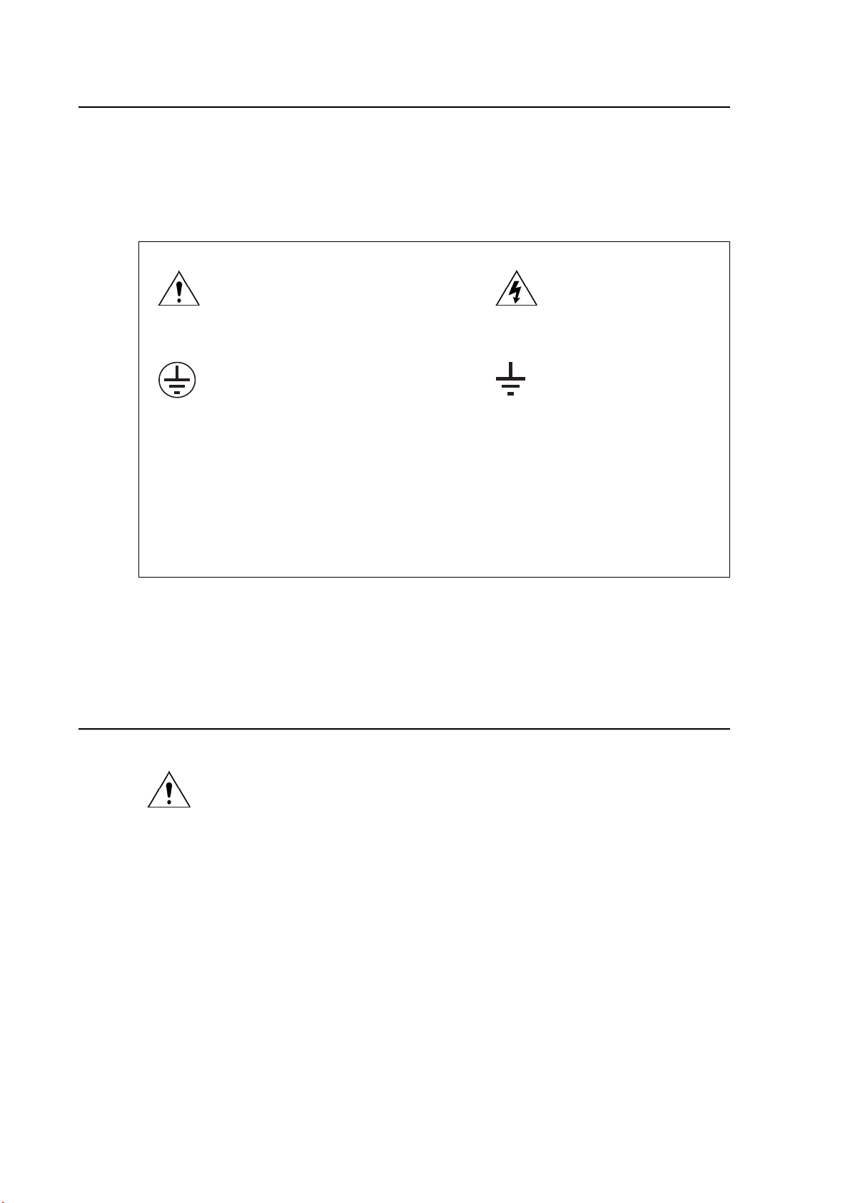
3.1 Symbols
Cautio
Protective Conductor (*Earth) terminal
3.2 Labels
n: refer to equipment documentation
*NOTE: THE TERM EARTH USED THROUGHOUT THIS TECHNICAL
MANUAL IS THE DIRECT EQUIVALENT OF THE NORTH
AMERICAN TERM GROUND.
Caution: risk of electric shock
Functional/Protective Conductor
(*Earth) terminal.
Note: This symbol may also be used
for a Protective Conductor
(Earth) Terminal if that
terminal is part of a terminal
block or sub-assembly e.g.
power supply.
See Safety Guide (SFTY/4
L M) for typical equipment labeling information.
4. INSTALLING, COMMISSIONING AND SERVICING
Equipment connections
Personnel undertaking installation, commissioning or servicing work for this
equipment should be aware of the correct working procedures to ensure safety.
The equipment documentation should be consulted before installing,
commissioning, or servicing the equipment.
Terminals exposed during installation, commissioning and maintenance may
present a hazardous voltage unless the equipment is electrically isolated.
The clamping screws of all terminal block connectors, for field wiring, using M4
screws shall be tightened to a nominal torque of 1.3 Nm.
Equipment intended for rack or panel mounting is for use on a flat surface of a
Type 1 enclosure, as defined by Underwriters Laboratories (UL).
Any disassembly of the equipment may expose parts at hazardous voltage, also
electronic parts may be damaged if suitable electrostatic voltage discharge (ESD)
precautions are not taken.
If there is unlocked access to the rear of the equipment, care should be taken by
all personnel to avoid electric shock or energy hazards.
Voltage and current connections shall be made using insulated crimp terminations
to ensure that terminal block insulation requirements are maintained for safety.
Page 11

Safety Section P44x/EN SS/H11
(SS) - 5
Watchdog (self-monitoring) contacts are provided in numerical relays to indicate
the health of the device. Alstom Grid strongly recommends that these contacts
are hardwired into the substation's automation system, for alarm purposes.
To ensure that wires are correctly terminated the correct crimp terminal and tool
for the wire size should be used.
The equipment must be connected in accordance with the appropriate connection
diagram.
Protection Class I Equipment
- Before energizing the equipment it must be earthed using the protective
conductor terminal, if provided, or the appropriate termination of the
supply plug in the case of plug connected equipment.
- The protective conductor (earth) connection must not be removed since
the protection against electric shock provided by the equipment would be
lost.
- When the protective (earth) conductor terminal (PCT) is also used to
terminate cable screens, etc., it is essential that the integrity of the
protective (earth) conductor is checked after the addition or removal of
such functional earth connections. For M4 stud PCTs the integrity of the
protective (earth) connections should be ensured by use of a locknut or
similar.
The recommended minimum protective conductor (earth) wire size is 2.5 mm²
(3.3 mm² for North America) unless otherwise stated in the technical data section
of the equipment documentation, or otherwise required by local or country wiring
regulations.
The protective conductor (earth) connection must be low-inductance and as short
as possible.
All connections to the equipment must have a defined potential. Connections that
are pre-wired, but not used, should preferably be grounded when binary inputs
and output relays are isolated. When binary inputs and output relays are
connected to common potential, the pre-wired but unused connections should be
connected to the common potential of the grouped connections.
Before energizing the equipment, the following should be checked:
- Voltage rating/polarity (rating label/equipment documentation);
- CT circuit rating (rating label) and integrity of connections;
- Protective fuse rating;
- Integrity of the protective conductor (earth) connection (where
applicable);
- Voltage and current rating of external wiring, applicable to the application.
Accidental touching of exposed terminals
If working in an area of restricted space, such as a cubicle, where there is a risk of
electric shock due to accidental touching of terminals which do not comply with
IP20 rating, then a suitable protective barrier should be provided.
Equipment use
If the equipment is used in a manner not specified by the manufacturer, the
protection provided by the equipment may be impaired.
Removal of the equipment front panel/cover
Removal of the equipment front panel/cover may expose hazardous live parts,
which must not be touched until the electrical power is removed.
Page 12
P44x/EN SS/H11 Safety Section
(SS) - 6
UL and CSA/CUL listed or recognized equipment
To maintain UL and CSA/CUL Listing/Recognized status for North America the
equipment should be installed using UL and/or CSA Listed or Recognized parts
for the following items: connection cables, protective fuses/fuseholders or circuit
breakers, insulation crimp terminals, and replacement internal battery, as
specified in the equipment documentation.
For external protective fuses a UL or CSA Listed fuse shall be used. The Listed
type shall be a Class J time delay fuse, with a maximum current rating of 15 A and
a minimum d.c. rating of 250 Vd.c. for example type AJT15.
Where UL or CSA Listing of the equipment is not required, a high rupture capacity
(HRC) fuse type with a maximum current rating of 16 Amps and a minimum d.c.
rating of 250 Vd.c. may be used, for example Red Spot type NIT or TIA.
Equipment operating conditions
The equipment should be operated within the specified electrical and
environmental limits.
Current transformer circuits
Do not open the secondary circuit of a live CT since the high voltage produced
may be lethal to personnel and could damage insulation. Generally, for safety,
the secondary of the line CT must be shorted before opening any connections to
it.
For most equipment with ring-terminal connections, the threaded terminal block
for current transformer termination has automatic CT shorting on removal of the
module. Therefore external shorting of the CTs may not be required, the
equipment documentation should be checked to see if this applies.
For equipment with pin-terminal connections, the threaded terminal block for
current transformer termination does NOT have automatic CT shorting on removal
of the module.
External resistors, including voltage dependent resistors (VDRs)
Where external resistors, including voltage dependent resistors (VDRs), are fitted
to the equipment, these may present a risk of electric shock or burns, if touched.
Battery replacement
Where internal batteries are fitted they should be replaced with the recommended
type and be installed with the correct polarity to avoid possible damage to the
equipment, buildings and persons.
Insulation and dielectric strength testing
Insulation testing may leave capacitors charged up to a hazardous voltage. At the
end of each part of the test, the voltage should be gradually reduced to zero, to
discharge capacitors, before the test leads are disconnected.
Insertion of modules and pcb cards
Modules and PCB cards must not be inserted into or withdrawn from the
equipment whilst it is energized, since this may result in damage.
Insertion and withdrawal of extender cards
Extender cards are available for some equipment. If an extender card is used,
this should not be inserted or withdrawn from the equipment whilst it is energized.
This is to avoid possible shock or damage hazards. Hazardous live voltages may
be accessible on the extender card.
Page 13
Safety Section P44x/EN SS/H11
External test blocks and test plugs
Great care should be taken when using external test blocks and test plugs such
as the MMLG, MMLB and MiCOM P990 types, hazardous voltages may be
accessible when using these. *CT shorting links must be in place before the
insertion or removal of MMLB test plugs, to avoid potentially lethal voltages.
*Note: When a MiCOM P992 Test Plug is inserted into the MiCOM P991 Test
Block, the secondaries of the line CTs are automatically shorted, making
them safe.
Fiber optic communication
Where fiber optic communication devices are fitted, these should not be viewed
directly. Optical power meters should be used to determine the operation or
signal level of the device.
Cleaning
The equipment may be cleaned using a lint free cloth dampened with clean water,
when no connections are energized. Contact fingers of test plugs are normally
protected by petroleum jelly, which should not be removed.
(SS) - 7
5. DE-COMMISSIONING AND DISPOSAL
De-commissioning
The supply input (auxiliary) for the equipment may include capacitors across the
supply or to earth. To avoid electric shock or energy hazards, after completely
isolating the supplies to the equipment (both poles of any dc supply), the
capacitors should be safely discharged via the external terminals prior to
de-commissioning.
Disposal
It is recommended that incineration and disposal to water courses is avoided.
The equipment should be disposed of in a safe manner. Any equipment
containing batteries should have them removed before disposal, taking
precautions to avoid short circuits. Particular regulations within the country of
operation, may apply to the disposal of the equipment.
6. TECHNICAL SPECIFICATIONS FOR SAFETY
Unless otherwise stated in the equipment technical manual, the following data is applicable.
6.1 Protective fuse rating
The
recommended maximum rating of the external protective fuse for equipments is 16A,
high rupture capacity (HRC) Red Spot type NIT, or TIA, or equivalent. The protective fuse
should be located as close to the unit as possible.
DANGER - CTs must NOT be fused since open circuiting them may
produce lethal hazardous voltages.
6.2 Protective class
IEC 60255
equipment documentation).
EN 60255-27: 2005 This equipment requires a protective
conductor (earth) connection to ensure user safety.
-27: 2005 Class I (unless otherwise specified in the
Page 14

P44x/EN SS/H11 Safety Section
(SS) - 8
6.3 Installation category
IEC 60255-27: 2005 Installation category III (Overvoltage Category III):
EN 60255-27: 2005 Distribution level, fixed installation.
Equipment in this category is qualification tested at
5 kV peak, 1.2/50 µs, 500 , 0.5 J, between all
supply circuits and earth and also between
independent circuits.
6.4 Environment
The equi
pment is intended for indoor installation and use only. If it is required for use in an
outdoor environment then it must be mounted in a specific cabinet of housing which will
enable it to meet the requirements of IEC 60529 with the classification of degree of
protection IP54 (dust and splashing water protected).
Pollution Degree - Pollution Degree 2 Compliance is demonstrated by reference to safety
Altitude - Operation up to 2000m standards.
IEC 60255-27:2005
EN 60255-27: 2005
Page 15

Introduction
6
MiCOM P40 Agile P442, P444
1
(IT) 1-
P44x/EN IT/Hb
INTRODUCTION
Date: 2017
Page 16

P44x/EN IT/H
b6
n
(IT) 1
MiCOM P40 Agile P442, P444
-2
Introductio
Page 17

Introduction
6
MiCOM P40 Agile P442, P444
3
(IT) 1-
P44x/EN IT/Hb
CONTENTS
1. INTRODUCTION TO MICOM GUIDES 5
2. INTRODUCTION TO MICOM 7
3. PRODUCT SCOPE 8
3.1 Ordering options 11
Page 18

P44x/EN IT/H
b6
n
(IT) 1
MiCOM P40 Agile P442, P444
-4
Introductio
Page 19

Introduction
6
MiCOM P40 Agile P442, P444
5
(IT) 1-
1 INTRODUCTION TO MiCOM GUIDES
This manual provides a functional and technical description of the MiCOM protection relay
and a comprehensive set of instructions for the relay ’s use and application.
The section contents are summarized below:
Safety Guide
P44x/EN IT Introduction
A guide to the MiCOM range of relays and the documentati on st ructure. General safety
aspects of handling Electronic Equipment is disc ussed with particular reference to relay
safety symbols. Also a general functional overview of the relay and brief application
summary is given.
P44x/EN TD Technical Data
Technical data including setting ranges, accuracy l i m its, recommended operating conditions,
ratings and performance data. Compliance with norms and i nt ernational standards is quoted
where appropriate.
P44x/EN GS Getting Started
P44x/EN IT/Hb
A guide to the different user interfaces of the protection relay describing how to start using it.
This section provides detailed information regarding the communication interfaces of the
relay, including a detailed description of how to access the settings database stored within
the relay.
P44x/EN ST Settings
List of all the relay settings, including ranges, step sizes and defaults, together with a brief
explanation of each setting.
P44x/EN AP Application Notes
This section includes a description of common power system applications of the relay,
calculation of suitable settings, some typical worked examples, and how to apply the settings
to the relay.
P44x/EN PL Programmable Logic
Overview of the programmable scheme logic a nd a description of each logical node. This
section includes the factory default (PSL) and an explanation of typical applications.
P44x/EN MR Measurements and Recording
Detailed description of the relays recording and measurements functions including the
configuration of the event and disturbance recorder a nd measurement functions.
P44x/EN FD Firmware Design
Overview of the operation of the relay’s hardware and software. This section includes
information on the self-checking features and di agnostics of the relay.
P44x/EN CM Commissioning
Instructions on how to commission the relay, comprising checks on the calibration and
functionality of the relay.
P44x/EN MT Maintenance
A general maintenance policy for the relay is out li ned.
P44x/EN TS Troubleshooting
Advice on how to recognize failure modes and the recommended course of action. Includes
guidance on who to contact for advice.
Page 20

P44x/EN IT/H
b6
n
(IT) 1
MiCOM P40 Agile P442, P444
Introductio
-6
P44x/EN SC SCADA Communications
This section provides an overview regarding the SCADA communication interfaces of the
relay. Detailed protocol mappings, semantics, profiles and interoperability tables are not
provided within this manual. Separate document s are available per protocol, available for
download from our website.
P44x/EN SG Symbols and Glossary
List of common technical abbreviations found within the product documentation.
P44x/EN IN Installation
Recommendations on unpacking, handling, inspect i on and storage of the relay. A guide to
the mechanical and electrical installation of t he relay is provided, incorporating earthing
recommendations. All external wiring connections to the relay are indicated.
P44x/EN CS Cyber Security (Software Version C7.x only, hardw are suffix K)
This section provides an overview about cyber security protection (to secure communication
and equipment within substations environment). Cy ber security standards and
implementation are described.
P44x/EN VH Firmware and Service Manual Version History
History of all hardware and software releases f or t he product.
Page 21

Introduction
6
MiCOM P40 Agile P442, P444
7
(IT) 1-
2 INTRODUCTION TO MiCOM
MiCOM is a comprehensive solution capable of meeting all electricity supply requirements. It
comprises a range of components, systems and services from General Electric.
Central to the MiCOM concept is flexibility.
MiCOM provides the ability to define an application solution and, through extensive
communication capabilities, to integrate it with your power supply control system.
The components in MiCOM are:
• P range protection relays;
• C range control products;
• M range measurement products for accurate metering and monitoring;
• S range versatile PC support and substation control packages.
MiCOM products include extensive facilities for recording information on the state and
behaviour of the power system using disturbance and fault records. They can also provide
measurements of the system at regular intervals to a cont rol centre enabling remote
monitoring and control to take place.
P44x/EN IT/Hb
For up-to-date information on any MiCOM product, visit our website:
http://www.gegridsolutions.com
Page 22

P44x/EN IT/H
b6
n
(IT) 1
MiCOM P40 Agile P442, P444
-8
3 PRODUCT SCOPE
The MiCOM P442 and P444 Numerical Full Scheme Distance Relays provide
comprehensive distance protection for different applications like: lines, cables, tapped lines,
lines with multiple zero sequence sources, non-homogeneous lines, series compensated
lines and parallel lines.
The independently settable resistive reach for e ach zone allows easy application to short
lines and cable protection. Using well-proven, patented techniques to directionalise, and
making full use of digital memory, the relays can be appl i ed i n situations that can cause
classic distance implementations to maloperat e (crosscountry faults and close-up faults).
The MiCOM P442 and P444 are in-built with a library of channel aided scheme logic,
supplementary and back-up protection. It prov ides complete protection (4 alternative setting
groups) to solidly earthed systems from distribut ion t o transmission voltage levels.
Three phase tripping with faulted phase indication is provided for all protection functions. In
addition models P442 and P444 allow single-pha se t ripping for the distance protection and
the channel aided DEF protection (67N).
The P442 and P444 distance relays equipped with 150 MHz CPU and coprocessor board
have been enhanced as described in the following table:
Introductio
Protection Functions Overview
ANSI IEC 61850 Features P442 P444
21P PDIS
21G PDIS
Load Blinder
50/51/67
50N / 51N
/ 67N
67N EfaPSCH
32N Directional zero sequence power protecti on
67/46
27 PTUV Undervoltage (4 stages, 1st stage DT and IDMT)
59 PTOV Overvoltage (4 stages, 1st stage DT and IDMT)
37 3-phase undercurrent (2 stages)
81U Underfr equency (4 stages)
81O Overfrequency (2 stages)
49 PTTR Thermal overload protection
50 / 27 PSOF Switch on to fault / trip on r ec lose (SOTF/TOR)
78 / 68 RPSB
85 PSCH Channel aided schemes (PUP, POP, Blocking)
Weak Infeed (WI) Echo logic
46BC Broken conductor (open jumper)
50ST OcpPTOC Stub bus protection
OcpPTOC
/ RDIR
EfdPTOC /
RDIR
NgcPTOC
/ RDIR
Quadrilateral full scheme phase di s tance (6
zones)
Quadrilateral full scheme ground d istance (6
zones)
Directional / non-directional phase overcurrent (2
stages)
Directional / non-directional stand by earth fault (2
stages)
Channel aided directional earth fault protection
(DEF)
Directional / non-directional negat ive sequence
overcurrent
Power swing blocking & Out of step tripping
(using PSL)
Accelerated trip feature: Loss of Load - Zx
extension
• •
• •
• •
• •
• •
• •
• •
• •
• •
• •
• •
• •
• •
• •
• •
• •
• •
• •
• •
• •
• •
Page 23

Introduction
6
MiCOM P40 Agile P442, P444
9
P44x/EN IT/Hb
(IT) 1-
Protection Functions Overview
ANSI IEC 61850 Features P442 P444
50BF RBRF Circuit breaker failure
PTRC Tripping 1/3p 1/3p
79 RREC Autoreclose (4 shots) 1/3p 1/3p
25 RSYN Check synchronism
VTS
CTS Current Transformer Supervision
CVTS Capacitive Voltage Transformer Supervision
51FF PTOC Emergency Overcurrent on VT failure
OptGGIO Digital inputs 16 24
RlyGGIO Output relays (fast output optional) 21
SV IEC 61850-9-2 sampled values
Front communication port (RS232/K-bus)
Time synchronisation port (IRI G-B) * option option
Voltage Transformer Supervision
(1, 2 & 3 phase fuse failure detection)
Rear communication port (RS485/Opt ic/Ethernet)
*
Second rear communication port
(RS232/RS485/K-Bus)*
IEC 61850-9-2-LE Sampled Analogue values
Ethernet board
• •
• •
• •
• •
• •
• •
32 or
46
• •
• •
• •
option option
option option
*It may be possible to get all in one particular model.
NA: Not applicable
To complement the wide range of protection functions listed in the table, the P442 and P444
relays are provided with the following measurement, control, monitoring, post fault
analysis and self-diagnostic functions.
• Fault locator
• Display of instantaneous measured and derived values
• Circuit breaker control, status & condition monitoring.
• Trip circuit and coil supervision
• 4 alternative setting groups
• Programmable scheme logic
• Sequence of event recording
• Comprehensive disturbance recording (waveform capture)
• User configurable LEDs
• Local and remote communication ports
• Multiple communication protocol and interface options
• Time synchronisation
• Fully customisable menu texts
• Multi level password protection
• Test facilities
• Power-up diagnostics and continuous self monitoring of the relay
Page 24
P44x/EN IT/H
b6
n
(IT) 1
MiCOM P40 Agile P442, P444
•
•
•
•
•
•
•
•
•
•
•
•
•
-10
• User friendly setting and analysis software (MiCOM S1 Agile)
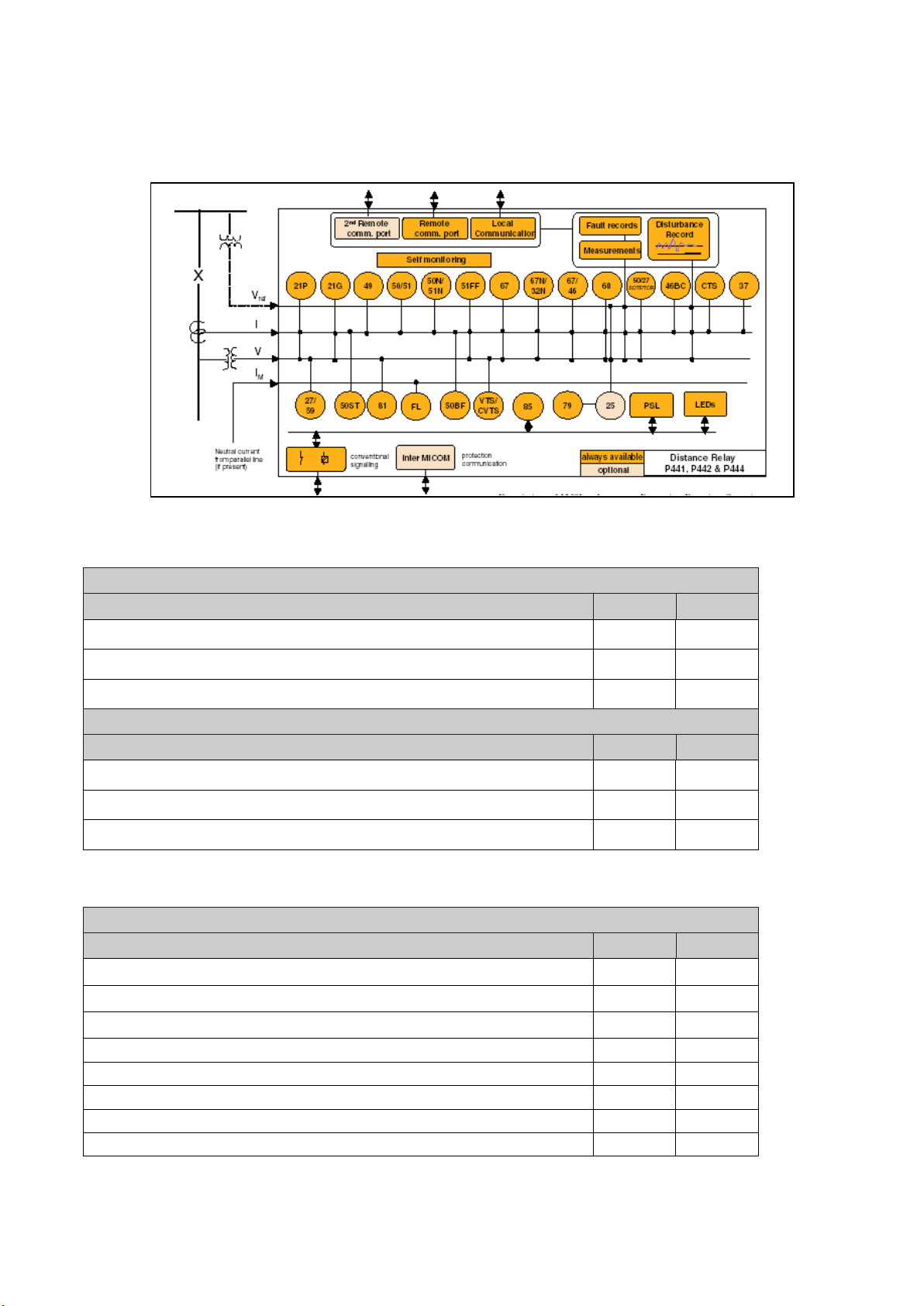
Application overview
Introductio
Figure 1: Functional diagram
Rating options
Auxiliary Voltage Rating options
Features P442 P444
24 – 48 Vdc only
48 – 110 Vdc (30 – 100 Vac)
110 – 250 Vdc (100 – 240 Vac)
In/Vn Rating boards options
Features P442 P444
Dual rated CT (1&5A: 100-120 V)
Module Sum (Σ1A / PXDB)
IEC 61850-9-2-LE Sampled Analogue values Ethernet board
Communication protocol options
Communication protocol options
Features P442 P444
K-Bus / Courier
MODBUS
VDEW (IEC 60870-5-103) (RS485 or Fibre Optic)
DNP3.0
IEC 61850 + Courier via rear RS485 port
IEC 61850 + IEC 60870-5-103 via rear RS485 port
DNP3.0 over Ethernet and Courier via r ear K-Bus/RS485
IEC 61850-9-2-LE
• •
• •
• •
• •
• •
•
•
•
•
Page 25
Introduction
6
MiCOM P40 Agile P442, P444
11
Dist ance Prot ection
P442 P44
2
**
Nominal auxiliary voltage
24-54 Vdc
7
48-125 Vdc (40-100 V ac)
8
110-250 Vdc (100-240 V ac)
9
In/Vn ra ting
Dual rated CT (1 & 5A : 100 - 120V ) 1
Module Sum
(∑
1A / PXDB)
5
C
Hardwa re options
Standard version
1
IRIG-B Only (Modul at ed) 2
3
4
Single Ethernet 100M bi t /s 6
Second Rear Comm s + Int erMi COM 7
IRIG-B (Modulated) + S econd Rear Comms + InterMiCOM 8
Single Ethernet (100Mbi t/s) plus IRIG-B (Modul ated) Software version '31' and later (S uffix J) A
Single Ethernet (100Mbi t/s) plus IRIG-B (Un-modul at ed) S oft ware version '31' and later (S uffix J) B
IRIG-B (Un-modulated) Soft ware version '31' and later (Suffix J) C
InterMiCOM + Courier Rear Port * E
InterMiCOM + Courier Rear Port + IRIG-B modulat ed *
F
Redundant Et hernet Self-Healing Ring, 2 m ul ti-mode fibre port s + Modul ated IRIG-B G
Redundant Et hernet Self-Healing Ring, 2 m ul ti-mode fibre port s + Un-modul at ed IRIG-B H
Redundant Et hernet RSTP, 2 mul t i -m ode fibre port s + M odul at ed IRIG-B J
Redundant Et hernet RSTP, 2 mul t i -m ode fibre port s + Un-modul ated IRIG-B K
Redundant Et hernet Dual -Homi ng Star, 2 m ul t i -m ode fibre port s + M odul at ed IRIG-B L
Redundant Et hernet Dual -Homi ng Star, 2 m ul t i -m ode fibre port s + Un-modul ated IRIG-B M
Redundant Et hernet PRP/ HS R**, 2 fibre port s + M odul at ed IRIG-B
N
Redundant Et hernet PRP/ HS R**
, 2 fibre ports + Unmodulat ed IRIG-B P
* NB: Options available wit h Software version 45 & lat er (Des i gn Suffix K)
** For HSR – c ont act Alstom for detai ls
Software options
16 Logic Inputs & 21 Relay Outputs B
16 Logic Inputs & 21 Relay Outputs (3 Fast trip) D
16 Logic Inputs & 21 Relay Outputs (6 Fast trip) E
16 Logic Inputs & 18 Relay Outputs (4 High Break) *
C
* NB: Option C is onl y available with Des i gn Suffix K & Software version 40 or lat er
Protocol options
K-Bus 1
Modbus
2
VDEW (IEC 60870-5-103)
3
DNP3.0 4
UCA2 + Courier via rear RS485 port (Ethernet hardware opti ons [i.e. 6] onl y) 5
IEC61850 + Courier via rear RS485 port * 6
IEC61850 + IEC60870-5-103 via rear RS485 port * 7
DNP3 over Ethernet wit h Courier rear port K-Bus /RS485 protocol
8
* NB: IEC61850 E di tion 2 available wit h '82' Software
Mounting
Flush Panel Mounting, wi t h Harsh Environment Coati ng M
Language
English, F renc h, German, S pani sh
0
English, F renc h, German, Ital i an 4
C
Software version
Date and application dependant **
Customer specific options
Standard version 0
Custom er engi neered version: ENEL 1
Custom er engi neered version: TERNA 2
Custom er engi neered version: RTE 4
Custom er engi neered version: general A
Hardware version
Model and hardware version dependant *
Chinese, E ngl i sh or French via HMI, wit h English or French onl y via
Communic ations port
Variants Order No.
Fibre opti c converter (Courier, Modbus,IEC60870-5-103 or DNP3)
(Note: c onverts RS 485 port to fibre optic; NOT ext ra port
)
IRIG-B input and Fibre optic converter (Courier, Modbus , IE C60870-5-103 or DNP3)
(
Note: converts RS485 port to fibre optic; NOT ext ra port)
Non-conventional input t ransformers NCIT (IEC 61850-9-2 LE)
(IT) 1-
3.1 Ordering options
P44x/EN IT/Hb
Page 26
P44x/EN IT/H
b6
n
(IT) 1
MiCOM P40 Agile P442, P444
Dist ance Protection P444 P444 **
Nominal auxiliary voltage
24-54 Vdc 7
48-125 Vdc (40-100 V ac) 8
110-250 Vdc (100-240 V ac) 9
In/Vn ra ting
Dual rated CT (1 & 5A : 100 - 120V ) 1
Module S um (∑1A / PXDB) 5
C
Hardware options
Standard version 1
IRIG-B input 2
Fibre opti c c onverter (IEC60870-5-103) 3
IRIG-B input and Fi bre opt i c converter (IEC60870-5-103) 4
Singl e E thernet 100M bi t /s 6
Rear Comms + InterMi COM 7
Rear Comms + IRIB-B + InterM i COM 8
Singl e E thernet (100M bit/s) plus IRIG-B (Modulat ed) S oft ware version '31' and later (Suffix J) A
Singl e E thernet (100M bit/s) plus IRIG-B (Un-modulated) S oft ware version '31' and later (S uffix J) B
IRIG-B (Un-modulated) (Soft ware version '31' and later) C
InterMiCOM + Couri er Rear Port * E
InterMiCOM + Couri er Rear Port + IRIG-B modulated
* F
Redundant Ethernet S el f-Healing Ri ng, 2 m ul ti-mode fibre port s + M odul at ed IRIG-B G
Redundant Ethernet S el f-Healing Ri ng, 2 m ul ti-mode fibre port s + Un-modul at ed IRIG-B H
Redundant Ethernet RS TP, 2 m ul ti-mode fibre port s + M odul ated IRIG-B J
Redundant Ethernet RS TP, 2 m ul ti-mode fibre port s + Un-m odul at ed IRIG-B K
Redundant Ethernet Dual-Hom i ng S tar, 2 m ul t i -m ode fibre port s + M odul ated IRIG-B L
Redundant Ethernet Dual-Hom i ng S tar, 2 m ul t i -m ode fibre port s + Un-m odulated IRIG-B M
Redundant Ethernet P RP /HSR, 2 fibre port s + M odul ated IRIG-B N
Redundant Ethernet P RP /HSR, 2 fibre port s + Unm odul at ed IRIG-B P
* NB: Opt i ons available with Software version 45 & later (Design Suffix K )
Models
1 & 3 Pol e tripping/recl osing with 24 input s & 32 out puts B
1 & 3 Pol e tripping/recl osing with 24 input s & 34 ouput s (12 high break ) C
1 & 3 Pol e tripping/recl osing with 24 input s & 32 out puts (4 fast output contac t s) D
1 & 3 Pol e tripping/recl osing with 24 input s & 32 out puts (8 fast output contac t s) E
1 & 3 Pol e tripping/recl osing with 24 input s & 46 out puts J
1 & 3 Pol e tripping/recl osing with 24 input s & 46 out puts (4 fast output contac t s) K
1 & 3 Pol e tripping/recl osing with 24 input s & 46 out puts (8 fast output contac t s) L
Protocol options
K-Bus 1
Modbus 2
VDEW (IEC 60870-5-103) (RS485 or Fibre O pt i c) 3
DNP3.0 4
UCA2 5
IEC61850 + Courier via rear RS485 port * 6
IEC61850 + IEC60870-5-103 via rear RS485 port
* 7
DNP3 over Ethernet wit h Courier rear port K -Bus/RS485 prot ocol
8
* NB: IEC61850 E di tion 2 available wit h '82' Software
Mounting
Flus h/Panel M ount i ng wi t h Hars h Environment Coati ng M
19" Rack Mounting wit h Harsh Environmental Coat i ng N
Language
Engli sh, F renc h, German, Spanis h 0
Engli sh, F renc h, German, It al i an 4
C
Software version
Date and applicat i on dependant
Customer specific options
Standard version 0
Customer engineered version: E NE L 1
Customer engineered version: TERNA 2
Customer engineered version: RTE 4
Customer engineered version: General A
Hardware version
Model and hardware version dependant *
Variant s Order No.
Chinese, English or Frenc h via HMI, wit h English or Frenc h onl y via Communic at i ons port
Non-conventional input transformers NCIT (IEC 61850-9-2 LE) NEW BO A RD
Introductio
-12
Page 27

Technical Data
6
MiCOM P40 Agile P442, P444
1
(TD) 2-
P44x/EN TD/Hb
TECHNICAL DATA
Date: 2017
Page 28

P44x/EN TD/H
b6
Technical Data
(TD)
MiCOM P40 Agile P442, P444
2-2
Page 29

Technical Data
6
MiCOM P40 Agile P442, P444
3
(TD) 2-
Technical Data
P442 & P444 Numerical Distance
Protection:
∗ 1 & 3 Pole tripping/reclosing (P442 & P444)
In/Vn rating (ordering option):
∗ Dual rated CT (1&5A: 100-120 V)
∗ Module sum (Σ1A / PXDB)
∗ IEC 61850-9-2LE Sampled Analogue
Values Ethernet board.
Input / Output (I/O)
P442 (with or without Check Synchronism):
∗ 16I/21O,
∗ 18I/18O (4 high break)
∗ 16I/21O (3 or 6 Fast Trip)
P444 (with or without Check Synchronism):
∗ 24I/32O,
∗ 24I/46O,
∗ 24I/34O (12 high break).
Protocol options:
∗ K-Bus
∗ Modbus,
∗ VDEW (IEC 60870-5-103)
∗ DNP3.0
+ (P442 and P444 only):
∗ IEC 61850 + Courier via rear RS485 port
∗ IEC 61850 + IEC 60870-5-103 via rear
RS485 port
∗ DNP3 over Ethernet with Courier rear port
K-Bus/RS485 protocol
Hardware options (P442 & P444):
∗ IRIG-B input
∗ Fibre optic converter (IEC 60870-5-103)
∗ IRIG-B input and Fibre optic converter
(IEC 60870-5-103)
∗ Single Ethernet 100 Mbit/s
∗ Rear Comms + InterMiCOM
∗ Rear Comms + IRIB-B + InterMiCOM
∗ Single Ethernet (100 Mbit/s) plus IRIG-B
(Modulated)
∗ Single Ethernet (100 Mbit/s) plus IRIG-B
(De-modulated)
∗ IRIG-B (De-modulated)
∗ InterMiCOM + Courier Rear Port *
∗ InterMiCOM + Courier Rear Port + IRIG-B
modulated *
∗ Redundant Ethernet Self-Healing Ring, 2
multi-mode fibre ports + Modulated IRIG-B
∗ Redundant Ethernet Self-Healing Ring, 2
multi-mode fibre ports + Un-modulated
IRIG-B
∗ Redundant Ethernet RSTP, 2 multi-mode
fibre ports + Modulated IRIG-B
∗ Redundant Ethernet RSTP, 2 multi-mode
fibre ports + Un-modulated IRIG-B
∗ Redundant Ethernet Dual-Homing Star, 2
multi-mode fibre ports + Modulated IRIG-B
∗ Redundant Ethernet Dual-Homing Star, 2
multi-mode fibre ports + Un-modulated
IRIG-B
P44x/EN TD/Hb
Mechanical Specification
Design
Modular MiCOM Px40 platform relay available
in three different case sizes:
∗ P442 60TE (12”),
∗ P444 80TE (16”).
Mounting:
∗ front of panel flush mounting,
∗ rack mounted (19” ordering option).
Enclosure Protection
Per IEC 60529: 1989
IP 52 Protection (front panel) against dust and
dripping water,
IP 50 Protection for the rear and sides of the
case against dust,
IP 10 Product safety protection for the rear due
to live connections on the terminal block.
Weight
40TE: approx. 7.3kg
60TE: approx. 9.2kg
80TE: approx. 11.0kg
Terminals
AC Current and Voltage Measuring Inputs
Located on heavy duty (black) terminal block:
Threaded M4 terminals, for ring lug
connection.
CT inputs have integral safety shorting, upon
removal of the terminal block.
General Input/Output Terminals
For power supply, opto inputs, output contacts
and COM1 & optional COM2 rear
communications.
Located on general purpose (grey) blocks:
Threaded M4 terminals, for ring lug
connection.
Case Protective Earth Connection
Rear stud connection, threaded M4.
Must be earthed (grounded) using the
protective (earth) conductor for safety,
minimum earth wire size 2.5 mm².
Front P
EIA RS232 DTE, 9 pin D-type female
connector.
Courier protocol for interface to MiCOM S1
Agile software.
PEB* rated Maximum cable length 15 m.
Front Download/Monitor Port
EIA RS232, 25 pin D-type female connector.
For firmware downloads. PEB* rated circuit.
Isolation to ELV level.
ort Serial PC Interface
Page 30

P44x/EN TD/
Hb6
Technical Data
(TD) 2
MiCOM P40 Agile P442, P444
-4
Rear Communications Port
K-Bus/EIA(RS485) signal levels, two wire
Connections located on general purpose block,
M4 screw.
For screened twisted pair cable, multidrop,
1000 m max.
SELV* rated circuit.
Ethernet (copper & fibre)
Optional Rear IRIG-B Interface modulated
or un-modulated
BNC socket
SELV* rated circuit.
50 ohms coaxial cable.
Optional Rear Fiber Connection for
SCADA/DCS
BFOC 2.5-(ST®)-interface for multi-mode
glass fibre type 62.5, as per IEC874-10,
850 nm short-haul fibers, one Tx and one Rx.
Optical budget: 5.6 dB
Data rate: 2.5 Mbits
Max Length: 1000 m
Optional Rear Ethernet Connection for
IEC 61850
10 Base T / 100 Base TX Communications
Interface in accordance with IEEE802.3 and
IEC 61850
Isolation: 1.5 kV.
Connector type: RJ45
Cable type: Screened Twisted Pair (STP)
Max. cable length: 100 m
100 Base FX Interface
Interface in accordance with IEEE802.3 and
IEC 61850
Wavelength: 1300 nm
Fiber: multi-mode 50/125 µm or 62.5/125 µm
Connector style: BFOC 2.5 - (ST®)
Optional Rear redundant Ethernet
connection for IEC 61850
100 Base FX Interface
Interface in accordance with IEEE802.3 and
IEC 61850
Wavelength: 1300 nm
Fiber: multi-mode 50/125 µm or 62.5/125 µm
Connector style: BFOC 2.5 - (ST®)
Fiber defect connector (watchdog relay)
Redundant Ethernet board
Connector (3 terminals): 2NC contacts
Rated voltage: 250 V
Continuous current: 5 A
Short duration current: 30 A for 3 s
Breaking capacity
DC: 50 W resistive
DC: 25 W resistive
AC: 1500 VA resistive (cos φ = unity)
AC: 1500 VA inductive (cos φ = unity)
Subject to maxima of 5 A and 250 V
Optional Second Rear Communication Port
EIA(RS)
232, 9 pin D-type female connector,
socket SK4. Courier protocol: K-Bus, or
EIA(RS)485 or EIA(RS)232. Maximum cable
length: 15 m.
*: PEB = Protective equipotential bonded
*: SELV = Safety/Separated extra low voltage
Both PEB and SELV circuits are safe to touch
after a single fault condition.
Page 31

Technical Data
6
MiCOM P40 Agile P442, P444
5
Ratings
(TD) 2-
P44x/EN TD/Hb
Power supply
AC Measuring Inputs
Nominal frequency:
∗ 50 and 60 Hz (settable)
Operating range:
∗ 45 to 65 Hz
AC Current
Nominal current (In):
∗ 1 and 5 A dual rated (separate terminals
are provided for the 1A and 5A windings,
with the neutral input of each winding
sharing one terminal)
Nominal burden per phase 1 A:
∗ <0.04 VA at rated current
Impedance per phase 1 A:
∗ <40 mΩ over 0 – 30 In
Nominal burden per phase 5 A:
∗ <0.15 VA at rated current
Impedance per phase 5 A:
∗ <8 mΩ over 0 – 30 In
Thermal withstand:
∗ continuous 4 In
∗ for 10 s: 30 In
∗ for 1 s; 100 In
Linear to 64 In (non-offset AC current).
AC Voltage
Nominal voltage (Vn):
∗ 100 to 120 V phase-phase
Nominal burden per phase:
∗ < 0.02 VA at 110/√3 V
Thermal withstand:
∗ continuous 2 Vn
∗ for 10 s: 2.6 Vn
Auxiliary Voltage (Vx)
Three ordering options:
(i) Vx: 24 to 48 Vdc
(ii) Vx: 48 to 110 Vdc, and 40 to 100Vac (rms)
(iii) Vx: 110 to 250 Vdc, and 100 to 240 V ac (rms).
Operating Range
(i) 19 to 65 V (dc only for this variant)
(ii) 37 to 150 V (dc), 32 to 110 V (ac)
(iii) 87 to 300 V (dc), 80 to 265 V (ac).
With a tolerable ac ripple of up to 12% for a dc
supply, per IEC 60255-11: 1979.
Nominal Burden
Quiescent burden: 12 W
Additions for energized binary inputs/out put s:
Per opto input:
∗ 0.09 W…(24 to 54 V),
∗ 0.12 W...(110/125 V),
∗ 0.19 W...(220/250 V).
Per energized output relay: 0.13 W
Per energized high break output relay: 0.73 W
Power-up Time
Time to power up < 11 s.
Power Supply Interruption
Per IEC 60255-11: 1979
The relay will withstand a 20 ms interruption in
the DC auxiliary supply, without de-energizing.
Per IEC 61000-4-11: 1994
The relay will withstand a 20 ms interruption in
an AC auxiliary supply, without de-energizing.
Battery Backup
Front panel mounted Type ½ AA, 3.6 V
Field Voltage Output
Regulated 48 Vdc
Current limited at 112 mA maximum output
The operating range shall be 40 V to 60 V with
an alarm raised at <35 V
Digital (“Opto”) Inputs
Universal opto inputs with programmable
voltage thresholds. May be energized from the
48 V field voltage, or the external battery
supply.
Rated nominal voltage: 24 to 250 Vdc
Operating range: 19 to 265 Vdc
Withstand: 300 Vdc.
Nominal pick-up and reset thresholds:
∗ Pick-up: approx. 70% of
battery nominal set,
∗ Reset: approx. 64% of
battery nominal set.
Recognition time:
∗ <2 ms with long filter removed,
∗ <10 ms with half-cycle ac immunity filter on.
Page 32

P44x/EN TD/
Hb6
Technical Data
(TD) 2
MiCOM P40 Agile P442, P444
-6
Output Contacts
Environmental Conditions
Standard Contacts
General purpose relay outputs for signalling,
tripping and alarming:
Rated voltage: 300 V
Continuous current: 10 A
Short-duration current:
∗ 30 A for 3 s
Making capacity:
∗ 250 A for 30 ms
∗ 10 A continuous.
Breaking capacity:
∗ DC: 50 W resistive
∗ DC: 62.5 W inductive (L/R = 50 ms)
∗ AC: 2500 VA resistive (cos φ = unity)
∗ AC: 2500VA inductive (cos φ = 0.7)
Response to command: < 5 ms
Durability:
∗ Loaded contact: 10000 operations
minimum,
∗ Unloaded contact: 100000 operations
minimum.
Fast operation and High Break Contacts
Dedicated purpose relay outputs for tripping:
∗ Uses IGBT technology
Make and Carry:
∗ 30 Amps for 3 sec, 30 A @ 250 V resistive
Carry:
∗ 250 Amps dc for 30 ms
Continuous Carry:
∗ 10 Amps dc
Break Capacity:
∗ 10 Amps @ 250 V resistive (10,000
operations) 10 Amps @ 250 V L/R=40 ms
Operating time:
∗ <200 µs & Reset time: 7.5 ms
Watchdog Contacts
Non-programmable contacts for relay
healthy/relay fail indication:
Breaking capacity:
∗ DC: 30 W resistive
∗ DC: 15 W inductive (L/R = 40 ms)
∗ AC: 375 VA inductive (cos φ = 0.7)
IRIG-B 12X Interface (Modulated)
External clock synchronization per IRIG
standard 200-98, format B12X.
Input impedance 6 kΩ at 1000 Hz
Modulation ratio:
∗ 3:1 to 6:1
Input signal, peak-peak:
∗ 200 mV to 20 V
Ambient Temperature Range
Ambient temperature range
Operating temperature range:
∗ –25°C to +55°C (or –13°F to +131°F)
Storage and transit:
∗ –25°C to +70°C (or –13°F to +158°F)
Tested as per IEC 60068-2-1: 2007:
∗ –25°C (–13°F) storage (96 hours)
∗ –40°C (–40°F) operation (96 hours)
IEC 60068-2-2: 2007:
∗ +70°C (+158°F) (storage (96 hours)
∗ +85°C (+185°F) operation (96 hours)
Ambient Humidity Range
Per IEC 60068-2-3: 1969:
∗ 56 days at 93% relative humidity and
+40 °C
Per IEC 60068-2-30: 1980:
∗ Damp heat cyclic, six (12 + 12) hour cycles,
93% RH, +25 to +55 °C
Pollution degree
Per IEC 61010-1:1990/A2:1995:
∗ Normally only non conductive pollution
occurs. Occasionally a temporary
conductivity caused by condensation mu st
be expected.
Corrosive Environments
Per IEC 60068-2-60: 1995, Part 2, Test Ke,
Method (class) 3
Industrial corrosive environment/poor
environmental control, mixed gas flow test.
21 days at 75% relative humidity and +30°C
Exposure to elevated concentrations of H
, Cl2 and SO2.
NO
2
2
S,
Type Tests
Insulation
Per IEC 60255-27: 2005,
∗ Insulation resistance > 100 M
(Using only electronic/brushless insulation
tester).
Creepage Distances and Clearances
Per IEC 60255-27: 2005
∗ Pollution degree 3,
∗ overvoltage category III,
∗ impulse test voltage 5 kV.
Ω at 500 Vdc
IRIG-B 00X Interface (Un-modulated)
External clock synchronization per IRIG
standard 200-98, format B00X.
Input signal TTL level
Input impedance at dc 10 kΩ
Page 33

Technical Data
6
MiCOM P40 Agile P442, P444
7
(TD) 2-
High Voltage (Dielectric) Wi th stand
(EIA RS232 ports excepted).
(i) Per IEC 60255-27: 2005, 2 kV rms, AC, 1
minute:
Between all case terminals connected togethe r
and the case earth.
Also, between all terminals of independent
circuits.
∗ 1 kV rms AC for 1 minute, across open
watchdog contacts and across open
contacts of changeover output relays.
(ii) Per ANSI/IEEE C37.90-1989 (reaffirmed
1994):
∗ 1.5 kV rms AC for 1 minute, across open
contacts of changeover output relays.
Impulse Voltage Withstand Test
Per IEC 60255-27: 2005
Front time: 1.2 µs, Time to half-value: 50 µs,
Peak value: 5 kV, 0.5J
Between all terminals, and all terminals and
case earth.
Electromagnetic Compatibility (EMC)
1 MHz Burst High Frequency Disturbance
Test
Per IEC 60255-22-1: 2008, Class III,
Common-mode test voltage: 2.5 kV,
Differential test voltage: 1.0 kV,
Test duration: 2 s, Source impedance: 200 Ω
(EIA RS232 ports excepted).
100 kHz Damped oscillatory Test
Per EN 61000-4-18: 2007, Level 3,
Common-mode test voltage: 2.5 kV,
Differential test voltage: 1.0 kV,
Immunity to Electrostatic Discharge
Per IEC 60255-22-2: 1997, Class 4,
∗ 15 kV discharge in air to user interface,
display, and exposed metalwork.
Per IEC 60255-22-2: 1997, Class 3,
∗ 8 kV discharge in air to all communication
ports.
∗ 6 kV point contact discharge to any part of
the front of the product.
Electrical Fast Transient or Burst
Requirements
Per IEC 60255-22-4: 2002 and EN 61000-4-4:
2004.
Test severity:
∗ Class III and IV:
Amplitude:
∗ 2 kV, burst frequency 5 kHz (Class III),
Amplitude:
∗ 4 kV, burst frequency 2.5 kHz (Class IV).
Applied directly to auxiliary supply, and applied
to all other inputs. (EIA RS232 ports
excepted).
Amplitude:
∗ 4 kV, burst frequency 5 kHz (Class IV).
Applied directly to auxiliary supply.
P44x/EN TD/Hb
Fast transient disturbances on power
supply (common mode only): 4 kV, 5 ns rise
time, 50 ns decay time, 5 kHz repetition
frequency, 15 ms burst, repeated every
300 ms for 1 min in each polarity, with a 50 Ω
source impedance
Fast transient disturbances on I/O signal,
data and control lines (common mode only):
4 kV, 5 ns rise time, 50 ns decay time, 5 kHz
repetition frequency, 15 ms burst, repeated
every 300 ms for 1 min in each polarity, with a
50 Ω source impedance.
Surge Withstand Capability
Per IEEE/ANSI C37.90.1: 2002:
4 kV fast transient and 2.5 kV oscillatory
applied directly across each output contact,
optically isolated input, and power supply
circuit.
Surge Immunity Test
(EIA RS232 ports excepted).
Per IEC 61000-4-5: 2006 Level 4,
Time to half-value: 1.2 / 50 µs,
∗ Amplitude: 4 kV between all groups and
case earth,
∗ Amplitude: 2 kV between terminals of each
group.
Immunity to Radiated Electromagnetic
Energy
Per IEC 60255-22-3: 2000, Class III:
Test field strength, frequency band 80 to 1000
MHz:
∗ 10 V/m,
∗ Test using AM: 1 kHz / 80%,
∗ Spot tests at 80, 160, 450, 900 MHz
Per IEEE/ANSI C37.90.2: 2004:
25 MHz to 1000 MHz, zero and 100% square
wave modulated.
Field strength of 35 V/m.
Radiated Immunity from Digital
Communications
Per EN61000-4-3: 2002, Level 4:
Test field strength, frequency band 800 to 960
MHz, and 1.4 to 2.0 GHz:
∗ 30 V/m,
Test using AM:
∗ 1 kHz / 80%.
Radiated Immunity from Digital Radio
Telephones
Per EN 61000-4-3: 2002
∗ 10 V/m, 900 MHz and 1.89 GHz.
Immunity to Conducted Disturbances
Induced by Radio Frequency Fields
Per IEC 61000-4-6: 1996, Level 3,
Disturbing test voltage: 10 Vrms at 1 kHz 80%
am., 0.15 to 80 MHz
Page 34

P44x/EN TD/
Hb6
Technical Data
(TD) 2
MiCOM P40 Agile P442, P444
-8
Power Frequency Magnetic Field Immunity
Per IEC 61000-4-8: 2001, Level 5,
∗ 100 A/m applied continuously,
∗ 1000 A/m applied for 3 s.
Per IEC 61000-4-9: 2001, Level 5,
∗ 1000 A/m applied in all planes.
Per IEC 61000-4-10: 2001, Level 5,
∗ 100 A/m applied in all planes at
100 kHz/1MHz with a burst duration of 2 s.
Conducted Emissions
Per EN 55022: 1998:
∗ 0.15 – 0.5 MHz, 79 dBµV (quasi peak)
66 dBµV (average)
∗ 0.5 – 30 MHz, 73 dBµV (quasi peak)
60 dBµV (average).
Mechanical Robustness
Vibration Test
Per IEC 60255-21-1: 1996
Response Class 2
Endurance Class 2
Shock and Bump
Per IEC 60255-21-2: 1995
Shock response Class 2
Shock withstand Class 1
Bump Class 1
Seismic Test
Per IEC 60255-21-3: 1995
Class 2
Radiated Emissions
Per EN 55022: 1998:
∗ 30 – 230 MHz, 40 dBµV/m at 10 m
measurement distance
∗ 230 – 1 GHz, 47 dBµV/m at 10 m
measurement distance.
EU Directives
EMC Compliance
Per 2004/108/EC:
Compliance to the European Commission
Directive on EMC is claimed via the Technical
Construction File route. Product Specific
Standards were used to establish conformity :
∗ EN50263: 2000
Product Safety
Per 2006/95/EC:
Compliance with European Commission Low
Voltage Directive. Compliance is demonstrat ed
by reference to generic safety standards:
∗ IEC 60255-27:2005
CE
R&TTE compliance
Radio and telecommunication terminal
equipment (R&TTE) directive 99/5/EC.
Compliance demonstrated by compliance to
both the EMC directives on low voltage
directive down to 0 V.
Applicable to rear communication ports.
Cyber Security
(where applicable)
Implementation
Following measures have been implemented:
∗ Four level access,
∗ Password strengthening,
∗ Disabling of unused application and
physical ports,
∗ Inactivity timer,
∗ Storage of security events,
∗ NERC-compliant default display.
Standards
∗ NERC CIP (North American Electric
Reliability Corporation – Critical
Infrastructure Protection, USA):
CIP-002-1, CIP-003-1, CIP-004-1,
CIP-005-1, CIP-006-1, CIP-007-1,
CIP-008-1 and CIP-009-1
∗ BDEW (Germany),
∗ ANSI ISA 99 (USA), IEEE 1686,
∗ IEC 62351, ISO/IEC 27002,
∗ NIST SP800-53 (National Institute of
Standards and Technology, USA),
∗ CPNI Guidelines (Centre for the Protection
of National Infrastructure, UK).
IEC 61850-9-2 Ethernet board
(option)
∗ connexion RJ45 or optical fibre
∗ Antialiasing filter
∗ Number of logical nodes: up to 6
∗ Time-delay at message
reception: 0 to 3 ms
Safety control:
∗
- presence test alarm,
- synchronization alarm,
- quality alarm,
independent per logical node
Page 35

Technical Data
6
MiCOM P40 Agile P442, P444
9
(TD) 2-
Timing and Accuracy
PERFORMANCE DATA
For all accuracies specified, the repeatability is
±
5%, unless otherwise specified
P44x/EN TD/Hb
Transient Overreach: Additional tolerance due
to increasing X/R ratios:
±5% over the X/R ratio from 1 to 90
Breaker fail timers accuracy:
20 ms or ±2%, whichever is greater
DISTANCE PROTECTION
All quoted operating times include the closure
of the trip output contact.
50 Hz Operation
Minimum tripping time: 13 ms (SIR = 5)
14 ms (SIR = 30)
Maximum tripping time: 18 ms (SIR = 5)
21 ms (SIR = 30)
Typical tripping time: 17 ms (SIR = 5)
17.5 ms (SIR = 30)
100% of faults up to 75% of Zone 1 reach
setting trip subcycle at SIR=5.
99% of faults up to 75% of Zone 1 reach
setting trip subcycle at SIR=30.
60 Hz Operation
Minimum tripping time: 13 ms (SIR = 5)
13 ms (SIR = 30)
Maximum tripping time: 16.5 ms (SIR = 5)
18 ms (SIR = 30)
Typical tripping time: 14 ms (SIR = 5)
16 ms (SIR = 30)
100% of faults up to 75% of Zone 1 reach
setting trip subcycle at SIR=5.
88% of faults up to 75% of Zone 1 reach
setting trip subcycle at SIR=30.
Accuracy
Characteristic shape, up to SIR = 30:
±5% for on-angle fault (the set line angle)
±10% for off-angle
(Example: For a 70 degree set line angle,
injection testing at 40 degrees would be
referred to as “off-angle”).
Zone time delay deviations:
±20 ms or 2%, whichever is greater
DIRECTIONAL AND NON-DIRECTIONAL
OVERCURRENT
(I>1, I>2, I>3 or I>4)
Accuracy
DT Pick-up: Setting ±5%
IDMT Pick-up 1.05 × Setting ±5%
DT reset: 0.95 × Setting ±2%
IDMT reset: 0.95 × Setting ±5%
Definite time stages:
±20 ms or ±2%, whichever is greater
Inverse time stages:
±40 ms or ±5%, whichever is greater
NEGATIVE SEQUENCE
OVERCURRENT
(I2>1, I2>2, I2>3 or I2>4)
Accuracy
Zone 1:
Pick-up: Setting ±5%
Reset: 0.95 × Setting ±5%
Definite time stages:
±40 ms or ±5%, whichever is greater
BROKEN CONDUCTOR DETECTION
Accuracy
(I2/I1)
Pick-up: Setting ±2.5%
Reset: 0.95 × Setting ±2.5%
Definite time stages:
±20 ms or 2%, whichever is greater
Sensitivity
Settings < 5/In Ω: (0.05 In*5/(setting*In)) ±5%
Settings > 5/In Ω: 0.05 In ±5%
Distance elements
Pick-up: Setting ±5%
Zone timer deviation:
20 ms or ±2%, whichever is greater
Timer accuracy: ±2 ms
Minimum trip level for IDMT elements:
1.05 × Setting ± 5%
Inverse time stages:
±40 ms or 5%, whichever is greater
Definite time stages:
±40 ms or 2%, whichever is greater
Repeatability: 5%
Sensitivity
Settings < 5/In Ω: (0.05 In*5/(setting*In)) ±5%
Settings > 5/In Ω: 0.05 In ±5%
Page 36

P44x/EN TD/
Hb6
Technical Data
(TD) 2
MiCOM P40 Agile P442, P444
-10
DIRECTIONAL AND NON-DIRECTIONAL
EARTH FAULT PROTECTION
(IN>1, IN>2, IN>3 or IN>4)
Accuracy
DT Pick-up: Setting ±5%
IDMT Pick-up 1.05 ×Setting ±5%
Drop-off: 0.95 × setting ±5%
Definite time stages:
±20 ms or ±2%, whichever is greater
DT reset: 0.95 × Setting ±2%
Inverse time stages:
40 ms or ±5%, whichever is greater
IDMT reset: 0.95 × Setting ±5%
AIDED DIRECTIONAL EARTH FAULT
(D.E.F.) PROTECTION
Accuracy
Zero Sequence Polarisation
pick-up: Setting ±10%
with relay characterist angle = ±90°
Negative Sequence Polarisation
pick-up: Setting ±5%
THERMAL OVERLOAD
Accuracy
Thermal alarm pick-up:
Calculated trip time ±10% ∗
Thermal overload pick-up:
Calculated trip time ±10% ∗
Cooling time accuracy
±15% of theoretical
Repeatability: <5%
∗ Operating time measured with applied
current of 20% above thermal setting.
UNDERCURRENT PROTECTION
(I<1,I<2)
Accuracy
Pick-up:
±10% or 0.025 In, whichever is greater
Drop-off: ±5%
Timer accuracy:
±40 ms or 2%, whichever is greater
Reset: <15 ms
UNDERVOLTAGE
(V<1, V<2, V<3 or V<4)
Accuracy
DT Pick-up: Setting ±2%
IDMT Pick-up: 0.95 × Setting ±2%
Definite time operation:
±20 ms or 2%, whichever is greater
IDMT characteristic shape:
±40 ms or 2%, whichever is greater
Reset: 1.05 × Setting ±5%
OVERVOLTAGE
(V>1, V>2, V>3 or V>4)
Accuracy
DT Pick-up: Setting ±1%
IDMT Pick-up: 1.05 x Setting ±2%
Definite time operation:
±20 ms or 2%, whichever is greater
IDMT characteristic shape:
±40 ms or 2%, whichever is greater
Reset: 0.98 to 0.995 × Setting ±5%
CIRCUIT BREAKER FAIL AND
UNDERCURRENT
NEUTRAL DISPLACEMENT/ RESIDUAL
OVERVOLTAGE
(VN>1, VN>2)
Accuracy
DT Pick-up: Setting ±5%
IDMT Pick-up: 1.05 x setting ±5%
Definite time operation:
±20 ms or 2%, whichever is greater
Instantaneous operation: <50 ms
IDMT characteristic shape:
±40 ms or 2%, whichever is greater
Reset: 0.95 × Setting ±5%
Accuracy
Pick-up:
±10% or 0.025
Operating time: <12 ms
Definite time operation:
±20 ms or 2%, whichever is greater
In, whichever is greater
VOLTAGE TRANSFORMER
SUPERVISION
Accuracy
Fast block operation: <1 cycle
Fast block reset: <1.5 cycles
Definite time operation:
±20 ms or 2%, whichever is greater
Page 37

Technical Data
6
MiCOM P40 Agile P442, P444
11
(TD) 2-
P44x/EN TD/Hb
CURRENT TRANSFORMER
SUPERVISION
Accuracy
IN> Pick-up: Setting ±5%
VN< Pick-up: Setting ±5%
IN> Drop-off: 0.9 × setting ±5%
VN< Drop-off:
(1.05 × settin g) ±5% or 1 V
whichever is greater
Time delay operation:
Setting ±2% or 20 ms
whichever is greater
CTS block operation: <1 cycle
CTS reset: <35 ms
CB STATE MONITORING AND
CONDITION MONITORING
Accuracy
Timers:
±20 ms or 2%, whichever is greater
Broken current accuracy: ±5%
PROGRAMMABLE SCHEME LOGIC
Accuracy
Output conditioner timer:
Setting ±20 ms or 2%, whichever is greater
Dwell conditioner timer:
Setting ±20 ms or 2%, whichever is greater
Pulse conditioner timer:
Setting ±20 ms or 2%, whichever is greater
AUTORECLOSE AND CHECK
SYNCHRONISM
Accuracy
Timers:
Setting ±20 ms or 2%, whichever is greater
MEASUREMENTS AND RECORDING
FACILITIES
Accuracy
Typically
0.2 - 2In/Vn
Current:
Range: 0.05 to 3 In
Accuracy: ±1.0% of reading
Voltage:
Range: 0.05 to 2 Vn
Accuracy: ±1.0% of reading
Power (W):
Range: 0.2 to 2 Vn and 0.05 to 3 In
Accuracy: ±5.0% of reading at
uni ty power factor
Reactive power (Vars):
Range: 0.2 to 2 Vn
and 0.05 to 3 In
Accuracy: ±5.0% of reading at
zero power factor
Apparent power (VA):
Range: 0.2 to 2 Vn
and 0.05 to 3 In
Accuracy: ±5.0% of reading
Energy (Wh):
Range: 0.2 to 2 Vn
and 0.2 to 3 In
Accuracy: ±5.0% of reading at
zero power factor
Energy (Varh):
Range: 0.2 to 2 Vn
and 0.2 to 3 In
Accuracy: ±5.0% of reading at
zero power factor
Phase accuracy:
Range: 0° to 360°
Accuracy: ±0.5%
Frequency:
Range: 45 t o 65 Hz
Accuracy: ±0.025 Hz
±
1%, but ±0.5% between
IRIG-B AND REAL TIME CLOCK
Performance
Real time clock accuracy:
< ±2 seconds/day
Modulation ratio: 1/3 or 1/6
Input signal peak-peak amplitude:
200 mV to 20 V
Input impedance at 1000 Hz: 6000 Ω External
clock synchronization:
Conforms to IRIG standard 200-98, format B
Page 38

P44x/EN TD/
Hb6
Technical Data
(TD) 2
MiCOM P40 Agile P442, P444
Parameter
Sym
Min.
Typ.
Max
Unit
Output Optical
EOL
Output Optical
EOL
Ratio
10
-10
dB
Output Optical
Logic “0” State
Parameter
Sym
Min.
Typ.
Max.
Unit
PIN
(W)
dBm avg.
PIN
(C)
Input Optical
Power Maximum
PIN
Max.
dBm avg.
(ms)
Max (ms)
Direct fiber
3 to 7
9
No Noise
5 to 8
+ MUX
12
+ MUX
BER
10-3
Direct fiber
4 to 8
10
No Noise
6 to 8
+ MUX
13
+ MUX
BER
≤10-3
-12
FAULT AND DISTURBANCE RECORDS
Accuracy
Time and date stamping:
±2 ms of applied fault/event
Fault clearance time: ±2%
CB operating time: ±5ms
Protection operating time: ±2%
Waveshape:
Comparable with applied quantities,
±5% of applied quantities
Trigger positions: ±2%
Record length: 8 records each of 1.8 s
duration (1.5 s at 60 Hz)
FAULT LOCATOR
Accuracy
Fault location: ±2% of line length (under
reference conditions)*
* Reference conditions solid fault applied on
line.
REFERENCE CONDITIONS
Ambient temperature: 20°C
FREQUENCY TRACKING RANGE
45 to 65 Hz
Ethernet data
(where applicable)
10 Base T /100 Base TX Communications
Interface in accordance with IEEE802.3 and
IEC 61850
Isolation 1.5 kV
Cable type: Screened twisted pair STP
Max length: 100 m
100 Base FX Interface
Interface in accordance with IEEE802.3 and
IEC 61850
Wavelength: 1300 nm
Fibre: multi-mode 50/125 µm or 62.5/12 5 µm
Connector style: ST
Transmitter Optical Characteristics
(TA = 0°C to 70°C, VCC = 4.75 V to 5.25 V)
BOL= Beginning of Life, EOL= End of Life
Power
BOL 62.5/125 µm,
NA = 0.275 Fiber
Power
BOL 50/125 µm,
NA = 0.20 Fiber
Optical Extinction
-19
PO
-20
-22.5
PO
-23.5
-16.8 -14
-20.3 -14
dBm avg.
dBm avg.
%
BREAKER FAILURE
Accuracy
Reset time < 40 ms ±2%
Thresholds: settings ±5%
Power at
PO
(“0”)
-45
dBm avg.
BOL – Beginning of life
EOL – End of life
Receive Optical Characteristics
(TA = 0°C to 70°C, VCC = 4.75 V to 5.25 V)
Input Optical
Power Minimum at
Window Edge
Input Optical
Power Minimum at
Eye Center
Min.
Min.
-14 -11.8
-33.5 –31
-34.5 -31.8 Bm avg.
InterMiCOM64 fiber optic
teleprotection
(where applicable)
End-end operation: Table below shows bit
transfer time (for multiplexed links, ‘MUX’
denotes the multiplexer delay).
IM64 Cmd Applic.
Typical
Delay
Note
Permissive
Dir. Intertrip
Via MUX
Via MUX
≤
BER – Bit Error Rate for Channel
Page 39

Technical Data
6
MiCOM P40 Agile P442, P444
13
(TD) 2-
SETTINGS, MEASUREMENTS
AND RECORDS LIST
SETTINGS LIST
GLOBAL SETTINGS (SYSTEM DATA):
Language:
English/French/German/Spanish/Italian/
Chinese (ordering option)
Frequency: 50/60 Hz
CONFIGURATION
Setting Group:
Select via Menu
Select via Opto
Active Settings: Group 1/2/3/4
Setting Group 1: Disabled/Enabled
Setting Group 2: Disabled/Enabled
Setting Group 3: Disabled/Enabled
Setting Group 4: Disabled/Enabled
Distance Protection: Disabled/Enabled
Power Swing: Disabled/Enabled
Back-Up I>: Disabled/Enabled
Negative Sequence
overcurrent: Disabled/Enabled
Broken Conductor: Disabled/Enabled
Earth Fault overcurrent
protection: Disabled/
Zero sequence power/
Earth fault overcurrent
Aided Directional Earth
Fault (DEF): Disabled/Enabled
Voltage Protection: Disabled/Enabled
Circuit Breaker Fail & I<: Disabled/Enabled
Supervision (Voltage,
Current or Capacitive
Voltage Transformer): Disabled/Enabled
System Checks: Disabled/Enabled
Thermal Overload: Disabled/Enabled
I< Protection: Disabled/Enabled
Residual Overvoltage
protection: Disabled/Enabled
Frequency Protection: Disabled/Enabled
Internal Autoreclose: Disabled/Enabled
Input Labels: Invisible/Visible
Output Labels: Invisible/Visible
CT & VT Ratios: Invisible/Visible
Record Control: Invisible/Visible
Disturbance Recorder: Invisible/Visible
Measure't Setup: Invisible/Visible
Communication Settings: Invisible/Visible
Commission Tests: Invisible/Visible
Setting Values: Primary/Secondary
Control Input: Invisible/Visible
Control Input Config: Invisible/Visible
Control Input Labels: Invisible/Visible
Direct Acces: Disabled/Enabled
InterMiCOM: Disabled/Enabled
Ethernet NCIT: Invisible/Visible
Function key: Invisible/Visible
RP1 / RP2 Read only Disabled/Enabled
NIC Read only Disabled/Enabled
PSL Timers: Invisible/Visible
RearPortt1ReadOnly Disabled/Enabled
RearPort2ReadOnly Disabled/Enabled
RearNICReadOnly Disabled/Enabled
LCD Contrast: (Factory pre-set)
P44x/EN TD/Hb
DISTANCE PROTECTION
Line setting
Line Length (Ln): 0.3 to 1000 km (step 0.010)
or 0.2 to 625 miles (step 0.005)
Line Impedance:
0.001×I1 to 500×I1 (step 0.001×I1)
Positive sequence angle (Line Angle, ϑ
–90.0° to +90° (step 0.1°)
):
1
Zone setting
Zone Status:
∗ Z1X Enabled/Disabled
∗ Z2 Enabled/Disabled
∗ ZP Enabled/Disabled
∗ ZQ Enabled/Disabled
∗ Z3 Enabled/Disabled
∗ Z4 Enabled/Disabled
Z1 (Impedance reach:) 0.001/In to 500/In Ω
(step 0.001/In Ω)
Z1X 0.001/In to 500/In Ω
(step 0.001/In Ω)
kZ1 residual
compensation factor: 0 to 7 (step 0.001)
KZ1 residual
compensation angle: 0 to +360° (step 0.1
R1G (Resistive reach for
phase-earth fault):
0 Ω to 400/In Ω (step 0.01/In Ω)
R1Ph (Resistive reach
for phase-phasefault):
0 Ω to 400/In Ω (step 0.01/In Ω)
tZ1 (time-delay
for Zone 1): 0 to 10 s (step 0.002 s)
Z2: 0.001/In to 500/In Ω (step 0.001/In/Ω)
kZ2 res comp: 0 to 7 (step 0.001)
kZ2 Angle: 0 to 360° (step 0.1°)
R2G: 0 Ω to 400/In Ω (step 0.01/In Ω)
R2Ph: 0 Ω to 400/In Ω (step 0.01/In Ω)
tZ2: 0 to 10 s (step 0. 002 s)
Z3: 0.001/In to 500/In Ω (step 0.001/In/Ω)
kZ3/4 res comp: 0 to 7 (step 0.001)
kZ3/4 Angle: 0 to 360° (step 0.1°)
R3G-R4G: 0 Ω to 400/In Ω (step 0.01/In Ω)
R3Ph-R4Ph: 0 Ω to 400/In Ω (step 0.01/In Ω)
tZ3: 0 to 10 s (step 0.002 s)
Z4: 0.001/In to 500/In Ω (step 0.01/In Ω)
tZ4: 0 to 10 s (step 0.01 s)
Zone P – Directionality Forward/Reverse
Zp: 0.001/In to 500/In Ω (step 0.001/In/Ω)
kZp res comp: 0 to 7 (step 0.001)
kZp Angle: 0 to 360° (step 0.1°)
RpG: 0 Ω to 400/In Ω (step 0.01/In Ω)
RpPh: 0 Ω to 400/In Ω (step 0.01/In Ω)
tZp: 0 to 10 s (step 0.002 s)
Zone Q – Directionality Forward/Reverse
Zq: 0.001/In to 500/In Ω (step 0.001/In/Ω)
kZq res comp: 0 to 7 (step 0.001)
kZq Angle: 0 to 360° (step 0.1°)
RqG: 0 Ω to 400/In Ω (step 0.01/In Ω)
RqPh: 0 Ω to 400/In Ω (step 0.01/In Ω)
tZq: 0 to 10 s (step 0.002 s)
°)
Page 40

P44x/EN TD/
Hb6
Technical Data
(TD) 2
MiCOM P40 Agile P442, P444
-14
Zone Setting other parameters
Serial Compensated
Line: Enabled/Disabled
Overlap Z mode: Enabled/Disabled
Z1m Tilt Angle: –45° to +45° (step 1°)
Z1p Tilt Angle: –45° to +45° (step 1°)
Z2/Zp/Zq Tilt Angle –45° to +45° (step 1°)
Fwd Z Chgt Delay: 0 to 100ms (step 1ms)
Volt. Memory Validity: 0 to 10 s (step 10 ms)
Earth Current detection:
0 to 0.1×I1 (step 0.01×I1)
Fault locator:
∗ KZm mutual Comp: 0 to 7 (step1)
∗ KZm Angle: 0 to 360° (step 1°)
Load Blinder:
∗ R< Blinder Lim: 0.001/In to 500/In Ω
(step 0.001/In/Ω)
∗ Load/B Angle: 15° to 65° (step 1°)
∗ Load Blinder V: 1 V to 70 V (step 0.5 V)
∗ None,
∗ Loss of Guard mode,
∗ Loss of Carrier mode.
Distance Scheme setting
Program mode Standard or open scheme
Standard Modes:
∗ Basic + Z1X,
∗ POP Z1,
∗ POP Z2,
∗ PUP Z2,
∗ PUP Forward,
∗ BOP Z1,
∗ BOP Z2.
POP = Permissive Overreach Protection
PUP = Permissive Underreach Protection
BOP = Blocking Overreach Protection
Fault type:
∗ Phase to Ground,
∗ Phase to Phase,
∗ Both enabled.
Trip Mode:
∗ Force 3 Pole,
∗ 1 Pole Z1 and Carrier Received (CR),
∗ POP Z1 Z2 and CR.
Signal sent from a zone to the relays setting
(open scheme):
∗ CsZ1 (Carrier sent by Z1),
∗ CsZ2,
∗ CsZ4.
Aided scheme on Carrier receipt “Dist CR”
(open scheme):
∗ None,
∗ PermZ1: Permissive Z1 (Z1 can trip without
waiting the end of tZ1 timout),
∗ PermZ2,
∗ PermFwd (forward),
∗ Blocking Z1 (BlkZ1) (Z1 can only trip if a
Carrier is not received),
∗ BlkZ2.
Additional time-delay for PUP Z2, PUP FWD,
POP Z1 and POP Z2 schemes:
0 to 1 s (stem 2 ms)
tReversal Guard: 0 to 0.15 s (step 2 ms)
Unblocking schemes (with permissive
schemes):
Page 41

Technical Data
6
MiCOM P40 Agile P442, P444
15
(TD) 2-
TOR (Trip On Reclose)–SOTF (Switch On To
Fault) modes enabled or disabled for:
∗ TOR logic in case of fault in Z1, Z2, Z3 or
All Zones,
∗ SOTF logic in case of fault in Z1, Z2, Z3 or
All Zones,
∗ TOR or SOTF in Distance scheme,
∗ SOTF logic in case of fault Z1+Rev,
Z2+Rev or I>3 Enabled,
∗ SOTF initiated by level detectors,
SOTF Delay: 10 to 3600 s (step 1 s)
Z1X extension on channel fail:
Enabled/Disabled
Weak Infeed
Mode Status:
Disabled/Echo/WI Trip & Echo/PAP
Single Pole: Disabled/Enabled
V< Threshold: 10 to 70 V (step 5 V)
Trip time delay: 0 to 1 s (step 2 ms)
Loss of Load (LoL)
Mode Status:
Enabled/Disabled
LoL on Channel failed: Enabled/Disabled
I<: 0.05×In to 1×In (step 0.05×In)
LoL Window: 0.01 s to 0.1 s (step 0.01 s)
POWER SWING DETECTION AND
BLOCKING
Power Swing detection boundaries:
∗ Delta R: 0 to 400/ In Ω (step 0.01/In Ω)
∗ Delta X: 0 to 400/ In Ω (step 0.01/In Ω)
IN Status: Enabled/Disabled
∗ IN> (%max) 10% to 100% (step 1%)
I2> Status: Enabled/Disabled
∗ I2> (%max) 10% to 100% (step 1%)
Imax line Status: Enabled/Disabled
∗ Imax line> (%max):
1×In to 20×In (step 0.01×In)
Delta I Status: Enabled/Disabled
Unblocking time-delay: 0 to 30 s (step 0.1 s)
Blocking zones:
∗ Z1/Z1X Block: Yes/No
∗ Z2 Block: Yes/No
∗ Zp Block: yes/No
∗ Zq Block: Yes/No
∗ Z3 Block: Yes/No
∗ Z4 Block Yes/No
Out of Step (OOS): 1 to 255 (step 1)
Stable swing: 1 to 255 (step 1)
P44x/EN TD/Hb
DIRECTIONAL AND NON DIRECTIONAL
OVERCURRENT PROTECTION
(Back-up I>)
Directional and non directional
I> protections:
I>1, I>2 (range 0.08–10×In)
Non directional I> protections:
I>3, I>4 (range 0.08–32×In)
I>1 Function / I>2 Function:
∗ Disabled,
∗ Definite Time (DT),
∗ IEC Standard inverse
∗ IEC Very inverse
∗ IEC Extremely inverse
∗ UK Long Time Inverse,
∗ IEEE Moderately Inverse,
∗ IEEE Very Inverse
∗ IEEE Extremely Inverse
∗ US Inverse
∗ US Short Time Inverse
∗ IN> (%max) 10% to 100% (step 1%)
I>1 / I>2 Directional:
∗ Non-directional,
∗ Directional forward
∗ Directional reverse
I>1 / I>2 VTS Block: Block/Non-directional
I>1 / I>2 current set: 0.08×In to 10.00×In
(step 0.01×In)
I>1 / I>2 Time-delay: 0 to 100 s (step 0.01 s)
I>1 / I>2 Time-delay
VTS: 0 to 100 s (step 0.01 s)
I>1 / I>2 Time Multiplier
Setting (TMS):
I>1 / I>2 Time Dial: 0.5 to 15 (step 0.1)
I>1 / I>2 Reset
characteristics: DT or Inverse
I>1 / I>2 tReset 0 to 100 s (step 0.01 s)
I>3 Status / I>4 Status: Enabled/Disabled
I>3 / I>4 current set: 0.08×In to 32.00×In
(step 0.01×In)
I>3 / I>4 Time-delay: 0 to 100 s (step 0.01 s)
0.025 to 1.2 (step 0.005)
NEGATIVE SEQUENCE
OVERCURRENT PROTECTION
Directional and non directional
I2> protections:
I2>1, I2>2 (range 0.08–4×In)
Non directional I2> protections:
I2>3, I2>4 (range 0.08–4×In)
I2>1 Function / I2>2 Function:
∗ Disabled,
∗ Definite Time (DT),
∗ IEC Standard inverse
∗ IEC Very inverse
∗ IEC Extremely inverse
∗ UK Long Time Inverse,
∗ IEEE Moderately Inverse,
∗ IEEE Very Inverse
∗ IEEE Extremely Inverse
Page 42

P44x/EN TD/
Hb6
Technical Data
(TD) 2
MiCOM P40 Agile P442, P444
-16
∗ US Inverse
∗ US Short Time Inverse
∗ IN> (%max) 10% to 100% (step 1%)
I2>1 / I2>2 Directional:
∗ Non-directional,
∗ Directional forward
∗ Directional reverse
I2>1 / I2>2 VTS Block: Block/Non-directional
I2>1 / I2>2 current set: 0.08×In to 4.00×In
(step 0.01×In)
I2>1 / I2>2 Time-delay:0 to 100 s (step 0.01 s)
I2>1 / I2>2 Time VTS:0 to 100 s (step 0.01 s)
I2>1 / I2>2 TMS: 0.025 to 1.2 (step 0.005)
I2>1 / I2>2 Time Dial: 0.01 to 100 (step 0.01)
I2>1 / I2>2 Reset
characteristics: DT or Inverse
I2>1 / I2>2 tReset 0 to 100 s (step 0.01 s)
I2>3 Status / I2>4 Status: Enabled/Disabled
I2>3 / I2>4 Directional:
∗ Non-directional,
∗ Directional forward
∗ Directional reverse
I2>3 / I2>4 VTS Block: Block/Non-directional
I2>3 / I2>4 current set: 0.08×In to 32.00×In
(step 0.01×In)
I2>3 / I2>4 Time-delay:0 to 100 s (step 0.01 s)
I2>3 / I2>4 Time VTS:0 to 100 s (step 0.01 s)
I>2 Char angle –95° to +95° (step 1°)
MAXIMUM OF RESIDUAL POWER –
ZERO SEQUENCE POWER
Zero Sequence Power Status:
Activated/Disabled
K Time delay factor: 0 to 2 (step 0.2)
Basis Time Delay: 0 to 10 s (ste p 0. 01 s)
Residual current: 0.05×In to 1×In
(step 0.01×In)
P0 threshold: 0.3 to 6.0 VA (step 30 mVA)
BROKEN CONDUCTOR DETECTION
Broken conductor: Enabled/Disabled
I2/I1 setting: 0.2 to 1 (step 0.01)
I2/I1Time Delay: 0 to 100 s (step 1 s)
I2/I1 Trip: Enabled/Disabled
DIRECTIONAL AND NON-DIRECTIONAL
EARTH FAULT OVERCURRENT
PROTECTION
Earth Fault O/C
Directional and non directional
IN> protections:
IN>1, IN>2 (range 0.08–10×In)
Non directional IN> protections:
IN>3, IN>4 (range 0.08–32×In)
IN>1 Function / IN>2 Function:
∗ Disabled,
∗ Definite Time (DT),
∗ IEC Standard inverse
∗ IEC Very inverse
∗ IEC Extremely inverse
∗ UK Long Time Inverse,
∗ IEEE Moderately Inverse,
∗ IEEE Very Inverse
∗ IEEE Extremely Inverse
∗ US Inverse
∗ US Short Time Inverse
∗ IN> (%max) 10% to 100% (step 1%)
IN>1 / IN>2 Directional:
∗ Non-directional,
∗ Directional forward
∗ Directional reverse
IN>1 / IN>2 VTS Block: Block/Non-directional
IN>1 / IN>2 current set: 0.08×In to 10.00×In
(step 0.01×In)
IN>1 / IN>2 Time-delay:0 to 200 s (step 0.01 s)
IN>1 / IN>2 Time VTS:0 to 200 s (step 0.01 s)
IN>1 / IN>2 TMS: 0.025 to 1.2 (step 0.005)
IN>1 / IN>2 Time Dial: 0.5 to 15 (step 0.01)
IN>1 / IN>2 Reset
characteristics: DT or Inverse
IN>1 / IN>2 tReset 0 to 100 s (step 0.01 s)
IN>3 Status / IN>4 Status: Enabled/Disabled
IN>3 / IN>4 Directional:
∗ Non-directional,
∗ Directional forward
∗ Directional reverse
IN>3 / IN>4 VTS Block: Block/Non-directional
IN>3 / IN>4 current set: 0.08×In to 32.00×In
(step 0.01×In)
IN>3 / IN>4 Time-delay:0 to 200 s (step 0.01 s)
IN>3 / IN>4 Time VTS:0 to 200 s (step 0.01 s)
IN> Directional
IN2 Char angle –95° to +95° (step 1°)
Polarisation:
∗ Zero Sequence,
∗ Negative Sequence.
Page 43

Technical Data
6
MiCOM P40 Agile P442, P444
17
(TD) 2-
AIDED DIRECTIONAL EARTH FAULT
(DEF) OVERVOLTAGE PROTECTION
Aided DEF Status: Enabled/Disabled
Polarisation:
∗ Zero Sequence,
∗ Negative Sequence.
V> Voltage set: 0.5 V to 20 V (step 0.01 V)
IN Forward: 0.05×In to 4×In (step0.01×In)
Time delay: 0s to 10 s (step 0.1 s)
Scheme logic: Shared/Blocking/Permissive
Tripping: Three Phase/Single Phase
Tp: 0 to 1000 ms (step 2 ms)
IN Rev Factor: 0 to 1 (step 0.1)
THERMAL OVERLOAD
Thermal characteristics:
Disabled/Single/Dual
Thermal trip:
0.08×In to 3.2×In (step 0.01×In)
Thermal alarm: 50% to 100% (step 1%)
Time constant 1: 1 mn to 200 mn (step 1 mn)
Time constant 2: 1 mn to 200 mn (step 1 mn)
RESIDUAL OVERVOLTAGE
VN Type: Residual/Homopolar∗
VN>1 function: Disabled/DT/IDMT
VN>1 voltage set: 1 V to 180 V (step 1 V)
homopolar: 0.5 V to 60 V (step 0.5 V)
VN>1 Time delay: 0 s to 100 s (step 0.01 s)
VN>1 TMS: 0.5 to 100 (step 0.5)
VN>1 tReset: 0 to 100 s (step 0.5 s)
VN>2 Status: Enabled/Disabled
VN>2 voltage set: 1 V to 180 V (step 1 V)
homopolar: 0.5 V to 60 V (step 0.5 V)
VN>2 Time delay: 0 s to 100 s (step 0.01 s)
∗
(software version C7.x only)
UNDERCURRENT PROTECTION
I< mode (threshold activation):
∗ I<1 status: activated/deactivated
∗ I<2 status: activated/deactivated
I<1 status: Enabled/Disabled
I<1 current set 0.08×I1 to 4×I1
(step 0.01×I1)
I<1 Time Delay: 0 to 100 s (step 0.01 s)
I<2 status: Enabled/Disabled
I<2 current set 0.08×I1 to 4×I1
(step 0.01×I1)
I<2 Time Delay: 0 to 100 s (step 0.01 s)
P44x/EN TD/Hb
VOLTAGE PROTECTION
V< & V> modes (threshold activation):
∗ V<1 function: activated/deactivated
∗ V<2 status: activated/deactivated
∗ V<3 status: activated/deactivated
∗ V<4 status: activated/deactivated
∗ V>1 function: activated/deactivated
∗ V>2 status: activated/deactivated
∗ V>3 status: activated/deactivated
∗ V>4 status: activated/deactivated
Undervoltage
V< Measurement mode:
∗ Phase–Neutrel,
∗ Phase–Phase
V<1 function: Disabled/DT/IDMT
V<1 voltage set 10 to 120 V (step 1 V)
V<1 Time Delay: 0 to 100 s (step 0.01 s)
V<1 TMS: 0.5 to 100 (step 0.5)
V<2, V<3 or V<4 status: Enabled/Disabled
V<2, V<3, V<4
voltage set:
10 to 120 V (step 1 V)
V<2, V<3 or V<4 Time Delay:
0s to 100 s (step 0.01 s)
Overvoltage
V> Measurement mode:
∗ Phase–Neutral,
∗
∗ Phase–Phase,
∗ Independent
V> % Hysteresis 0.1 to 2 % (step 1 %)
V>1 function: Disabled/DT/IDMT
V>1 voltage set 10 to 120 V (step 1 V)
V>1 Time Delay: 0 to 100 s (step 0.01 s)
∗
V>1 TMS: 0.5 to 100 (step 0.5)
V>2, V>3 or V>4 status: Enabled/Disabled
V>2, V>3, V>4 voltage set:
10 to 120 V (step 1 V)
V>2, V>3 or V>4 Time Delay:
0 s to 100 s (step 0.01 s)
FREQUENCY PROTECTION
Underfrequency
F<1 Status: Disabled/Enabled
F<1 Setting: 45 Hz to 65 Hz (step 0.01 Hz°
F<1 Time Delay: 0 to 100 s (step 0.01 s)
F<2, F<3 or F<4 Status: Disabled/Enabled
F<2, F<3 or F<4 Setting:
45 Hz to 65 Hz (step 0.01 Hz°
F<2, F<3 or F<4 Time Delay:
0 to 100 s (step 0.01 s)
Overfrequency
F>1 Status: Disabled/Enabled
F>1 Setting: 45 Hz to 65 Hz (step 0.01 Hz°
F>1 Time Delay: 0 to 100 s (step 0.01 s)
F>2 Status: Disabled/Enabled
F>2 Setting: 45 Hz to 65 Hz (step 0.01 Hz°
F>2 Time Delay: 0 to 100 s (step 0.01 s)
Page 44

P44x/EN TD/
Hb6
Technical Data
(TD) 2
MiCOM P40 Agile P442, P444
-18
CIRCUIT BREAKER FAIL AND I<
PROTECTION (CB FAIL & I<)
Circuit Breaker Fail
CB Fail 1 Status: Disabled/Enabled
CB Fail 1 timer: 0 to 10 s (step 0.01 s)
CB Fail 2 Status: Disabled/Enabled
CB Fail 2 timer: 0 to 10 s (step 0.01 s)
CB Fail Non I reset:
∗ I< only,
∗ CB Open & I<,
∗ Prot reset & I<,
∗ Prot reset or I<,
∗ Disable
CBF Ext reset:
∗ I< only,
∗ CB Open & I<,
∗ Prot reset & I<,
∗ Prot reset or I<,
∗ Disable
Undercurrent I<:
I< current set:
0.05×In to 3.2×In (step 0.01×In)
NON-PROTECTION FUNCTIONS
SETTINGS
CB CONDITION
CB Operations (number): 0 to 10000 (step 1)
CBA Operations: 0 to 10000 (step 1)
CBB Operations: 0 to 10000 (step 1)
CBC Operations: 0 to 10000 (step 1)
Total IA Broken: 0 to 25000 In^ (step 1 In^)
Total IB Broken: 0 to 25000 In^ (step 1 In^)
Total IC Broken: 0 to 25000 In^ (step 1 In^)
CB Operate time: 0 to 0.5 s (step 0.001)
Reset CB Data: Yes/No
Total 1P Reclosures: 0 to 0.85 s (0.001)
Total 3P Reclosures: 0 to 0.85 s (0.001)
Reset Total A/R: Yes/No
CB MONITOR SETUP
Broken I^: 0 to 2 (step 0.1)
I^Maintenance:
∗ Alarm Enabled/Alarm Disabled
∗ 1In^ to 25000In^ (step 1In^)
I^ Lockout:
∗ Alarm Enabled/Alarm Disabled
∗ 1In^ to 25000In^ (step 1In^)
Number CB Operations Maintenance:
∗ Alarm Enabled/Alarm Disabled
∗ 1 to 10000 (step 1)
CB Operating time Maintenance:
∗ Alarm Enabled/Alarm Disabled
∗ 0.005 s to 0.5 s (step 0.001 s)
CB Operating time Lockout Maintenance:
∗ Alarm Enabled/Alarm Disabled
∗ 0.005 s to 0.5 s (step 0.001 s)
CB Fault frequency:
∗ Lock: Alarm Enabled/Alarm Disabled
∗ Count: 0 to 9999 (ste p 1)
Fault frequency time: 0 to 9999 s (step 1 s)
Lockout reset: Yes/No
Reset Lockout by: CB Close/User interface
Man Close reset delay: 0.01 to 600 (step 1)
CB CONTROL
CB Control by:
∗ Disabled,
∗ Local,
∗ Remote,
∗ Local + Remote,
∗ Opto-input,
∗ Opto input + Local,
∗ Opto input + Remote,
∗ Opto input + Local + Remote.
Close Pulse Time: 0.1 s to 10 s (step 0.01 s)
Trip Pulse Time: 0.1 s to 5 s (step 0.01 s)
Man Close Delay:0.01 s to 600 s (step 0.01 s)
Healthy Window:0.01 s to 9999 s (step 0.01 s)
Check Synchronizing (C/S) Window:
0.01 s to 9999 s (step 0.01 s)
A/R Single Pole: Enabled/Disabled
A/R Three Pole: Enabled/Disabled
CT AND VT RATIOS
Main VT ratios: 100 V to 1M V (step 1 V)
Main VT’s Secondary:
80 V to 140 V (step 1 V)
4th VT:
∗ Primary: 100 V to 1M V (step 1 V)
∗ Secondary 80 V to 140 V (step 1 V)
Phase CT:
∗ Primary: 1A to 30 kA (step 1A)
∗ Secondary 1A/5A
Mutual Compensation CT: (can also be used
for Residual Current measurement)
∗ Primary: 1A to 30 kA (step 1A)
∗ Secondary 1A/5A
Check Synchronizing (C/S) input:
A (phase A)–N (Neutral)/
B–B/C–N/A–B/B–C/C–A
Main VT Location: Line/Bus
CT polarity: Standard/Inverted
Measured VN Disabled
Measured IN Disabled
SEQUENCE OF EVENT RECORDER
(RECORD CONTROL)
Clear Events: Enabled/Disabled
Clear Faults: Enabled/Disabled
Clear Maint: Enabled/Disabled
Alarm Event: Enabled/Disabled
Relay O/P Event: Enabled/Disabled
Opto Input Event: Enabled/Disabled
System Event: Enabled/Disabled
Fault Rec Event: Enabled/Disabled
Maint Rec Event: Enabled/Disabled
Protection Event: Enabled/Disabled
DDB 31 – 0: (up to):
DDB 2047 – 2016:
Binary function link strings, selecting whi ch
DDB signals will be stored as events, and
which will be filtered out
Page 45

Technical Data
6
MiCOM P40 Agile P442, P444
19
(TD) 2-
MEASURED OPERATING DATA
(MEASURE'T SETUP)
Default Display:
∗ Description
∗ Plant reference,
∗ U – I – Freq,
∗ P – Q,
∗ Date and Time.
Local Values: Primary/Secondary
Remote Values: Primary/Secondary
Measurement Ref: VA/VB/VC/IA/IB/IC
Measurement Mode: 0/1/2/3
Demand Interval: 1…99mn (step 1mn)
Distance Unit: Miles/Kilometres
Fault Location:
Distance
Ohms
% of Line
COMMUNICATIONS COLUMN
Courier protocol:
Protocol indicated
RP1 Address: 7 to 34 (step 1)
RP1 Inactiv timer: 1mn to 30 mn (step 1mn)
Physical link: RS485, Fibre optic
RP1 Status
RP1 Port configuration: Kbus/EIA(RS)485
RP1 comms mode:
∗ IEC 60870 FT1.2
∗ 10-Bit no parity
RP1 Baud Rate: 9600/19200/38400 bits/s
IEC 60870-5-103 protocol:
Protocol indicated
RP1 Address: 7 to 34 (step 1)
RP1 Inactiv timer: 1mn to 30 mn (step 1 mn)
Baud Rate: 9600/19200/38400 bits/s
Measurement period: 1 to 60 s (step 1 s)
CS103 blocking:
∗ Disabled,
∗ Monitor blocking,
∗ Command blocking.
RP1 Status
RP1 Port configuration: Kbus/EIA(RS)485
RP1 comms mode:
∗ IEC 60870 FT1.2
∗ 10-Bit no parity
RP1 Baud Rate: 9600/19200/38400 bits/s
Modbus protocol:
Protocol indicated
RP1 Address: 7 to 34 (step 1)
RP1 Inactiv timer: 1mn to 30 mn (step 1 mn)
Baud Rate: 9600/19200/38400 bits/s
Parity: Odd/Even/None
Physical link: RS485/Fibre optic
Date/Time Format: Enabled/Disabled
RP1 Status
RP1 Port configuration: Kbus/EIA(RS)485
RP1 comms mode:
∗ IEC60870 FT1.2
∗ 10-Bit no parity
RP1 Baud Rate: 9600/19200/38400 bits/s
P44x/EN TD/Hb
DNP3.0 protocol:
Protocol indicated
RP1 Address: 7 to 34 (step 1)
RP1 Inactiv timer: 1 mn to 30 mn (step 1 mn)
Baud Rate: 9600/19200/38400 bits/s
Parity: Odd/Even/None
Measurement period: 1 to 60 s (step 1 s)
Physical link: RS485/Fibre optic
Time Synhronization: Enabled/Disabled
Date/Time Format: Enabled/Disabled
RP1 Status
RP1 Port configuration: Kbus/EIA(RS)485
RP1 comms mode:
IEC 60870 FT1.2/10-Bit no parity
RP1 Baud Rate: 9600/19200/38400 bits/s
Scale Value indicated
Message Gap: 0 to 50 ms (step 1 ms)
DNP Need Time: 1 to 30 (step 1)
DNP Application fragment size:
100 to 2048 (step 1)
DNP Application fragment timeout:
1 s to 120 s (step 1 s)
DNB SBO timeout: 1 s to 10 s (step 1 s)
DNP link timeout: 0 to 120 s (step 1 s)
Ethernet port, IEC 61850 protocol:
Protocol indicated
Protocol & Scale value indicated,
Network Interface Card (NIC) protocol:
Courier/IEC
NIC MAC Adress indicated,
NIC tunnel timeout: 1 to 30 mn (step 1 mn)
NIC Link Report: Alarm/Even/None
Ethernet port, DNP3.0 protocol:
Protocol, IP address, subnet mask, NIC MAC
address and Gateway address indicated,
DNP time synchro: Enabled/Disabled
DNP Meas scaling:
Primary/Secondary/Normalized
RP1 Address: 7 to 34 (step 1)
RP1 Inactiv timer: 1 mn to 30 mn (step 1 mn)
Baud Rate: 9600/19200/38400 bits/s
Parity: Odd/Even/None
NIC tunnel timeout: 1 to 30 mn (step 1 mn)
NIC Link Report: Alarm/Even/None
SNTP parameters:
Primary and Secondary SNTP addresses
displayed
SNTP poll rate: 64 to 1024 s (step 1 s)
SNTP need time: 1 to 30 mn (step 1 mn)
SNTP Application
Fragment size: 100 to 2048 (step 1)
SNTP Application
fragment timeout: 1 s to 120 s (step 1 s)
SNTP SBO timeout: 1 s to 10 s (step 1 s)
Second rear port connection setting:
Protocol and Status indicated
RP2 Port configuration:
Kbus/EIA(RS)485/EIA RS232
RP2 comms mode:
IEC60870 FT1.2/10-Bit no parity
RP2 Address: 0 to 255 (step 1)
RP2 Inactivity timer: 1 to 30 mn (step 1 mn)
RP2 Baud Rate: 9600/19200/38400 bits/s
60870-5-103/Modbus/DNP3.0
Page 46

P44x/EN TD/
Hb6
Technical Data
(TD) 2
MiCOM P40 Agile P442, P444
-20
COMMISSIONING TESTS
Status of opto-isolated inputs indication,
Status of output relays indication,
Status of test port indication,
Status of LEDs indication,
Monitor Bit 1(up to 8):
Binary function link strings, selecting whi ch
DDB signals have their status visible in the
Commissioning menu, for test purposes
Test Mode: Enabled or Disabled
87BB and 50BF trip blocked per zone
Test Pattern:
Configuration of which output contacts are t o
be energized when the contact test is
applied.
Contact test:
No operation/Apply test/Remove test
LEDs test,
Autoreclose test:
No operation/ 3-pole test/
Pole A, B or C test
Red or Green LED status visible,
DDB31-0 to DDB 2047-2016 status visible.
OPTO CONFIGURATION
Opto input voltage range:
∗ 24-27 V
∗ 30-34 V
∗ 48-54 V
∗ 110-125 V
∗ 220-250 V
Custom
Opto Input 1
(up to # = max. opto no. fitted)
Custom options allow independent thresholds
to be set per opto, from the same range as
above
HOTKEYS AND CONTROL INPUTS
Control Inputs operation (CTRL inputs
menu) menu:
Status of control inputs indication,
Control inputs operation:
Set/Reset/No operation
Control Inputs configuration (CTRL I/P
config. Menu):
The control inputs can be individually assigned
to the hotkeys by stetting,
Control input configuration: Latched/Pulsed
Following text displayed in the hotkey menu
can be set: Set/Reset / In/Out /
Enabled/Disabled / On/Off
Opto Input Labels (Opto I/P Labels menu)
User defined text string to describe the
function of the particular opto input.
Teleprotection (InterMiCOM comms)
Source Address: 0 to 10 (step 1)
Received Address: 0 to 10 (step 1)
Baud rate:
∗ 600 Baud
∗ 1200 Baud
∗ 2400 Baud
∗ 4800 Baud
∗ 9600 Baud
∗ 19200 Baud
Channels statistics: Visible/Invisible
∗ Nbr of tripping messages received
∗ Nbr blocking messages received,
∗ Number of messages received: tripping,
blocking, total and incorrect,
∗ Lost messages,
∗ Elapsed time,
∗ Reset statistics: Yes/No
Channel diagnostics: Visible/Invisible
∗ “Data carrier detect” status,
∗ Frame synchronization status,
∗ Message status,
∗ Channel status,
∗ InterMiCOM hardware status.
Loopback Mode: Internal/External/Disabled
Configuration of which InterMiCOM signals
are to be energized when the loopback test is
applied.
∗ User defined test pattern,
∗ Loopback status
InterMiCOM configuration
IM Msg Alarm Level: 0 to 100.0% (step 1%)
InterMiCOM command Types:
∗ IM1, IM2, IM3 and IM4 Command types:
Disabled/Direct/Blocking
∗ IM5 Cmd Type:
Disabled/Permissive/Direct
∗ IM6, IM7 and IM8 Command types:
Disabled/Permissive/Direct
Fallback mode:
Default/Latched
Default value: 0/1
Frame Synchronization Time:
10 ms to 1.50 s (step 10 ms)
Function keys
10 function keys:
∗ Status: Disabled/Locked/Unlocked
Mode: toggled/Normal
∗
∗ Label: User defined
Ethernet NCIT
(MiCOM P444 relays with IEC 61850-9-2 board only)
Physical Link: Copper/Fibre optic
AntiAlaising Filter: Enabled/Disabled
Merge Unit Delay: 0 to 3 ms (step 250 µs)
Logical Nodes (LN) Arrangement:
VL,IL,IN / VL,IL,IN2 / VL,IL,IN,VB/
VL,IL,IN2,VB / VL,IL,IN2,IN,VB
VL,Sum(2xIL) / VL,IL,IN,2xVB
VL,IL,IN2,2xVB’
Logical Nodes: 4
Page 47

Technical Data
6
MiCOM P40 Agile P442, P444
21
(TD) 2-
P44x/EN TD/Hb
IED configurator (IEC61850)
MiCOM P442 & P444 only
Switch between active or inactive configuratio n
banks,
MiCOM Configuration Language (MCL) files
restoration.
IEC 61850 configuration data displayed:
∗ Active / inactive Memory banks,
∗ Configuration revision number of Active or
inactive Memory bank,
∗ IP address, mask and Gateway conneced,
∗ SNTP: IP address of the primary and
secondary servers,
∗ IED name,
∗
IEC61850 GOOSE
∗ GOENA setting,
∗ test mode,
∗ Ignore test flag option
Supervision
VT Supervision
∗ Time-delay: 1 to 20 s (step 1 s)
∗ I2&I0 inhibition: 0 to 1A (step1 mA)
∗ 3P voltage detection: Enabled/Disabled
∗ Threshold 3P 10 to 70 V (step 1 V)
CT Supervision
∗ Status: Enabled/Disabled
∗ VN< Inhibition:
0.5 to 22 V (step 0.5 V)
or 2 V to 88 V (step 2 V)
∗ IN> setting 0.08×In to 4×In (step 0.01×In)
∗ Time-delay: 0 to 10 s (step 1 s)
CVT Supervision
∗ Status: Enabled/Disabled
∗ VN>: 0.5 to 22 V (step 0.5 V)
∗ Time-delay: 0 to 300 s (step 0.01 s)
∗ V2 Status: Enabled/Disabled
∗ V2>: 0.5 to 22 V (s tep 0.5 V)
Autorecloser
Autoreclose mode:
Number of shots:
∗ 1P trip mode: 1, 1/3, 1/ 3/3 or 1/3/3/3
∗ 3P trip mode: 3, 3/3, 3/ 3/3 or 3/3/3/3
1P – Dead time 1 0.1 s to 5 s (step 0.01 s)
1P – Dead time 1 0.1 s to 60 s (step 0.01 s)
Dead time 2 1 s to 3600 s (step 1 s)
Dead time 3 1 s to 3600 s (step 1 s)
Dead time 4 1 s to 3600 s (step 1 s)
Reclaim time: 1 to 600 s (step 1 s)
Reclose time-delay: 0.1 s to 10 s (step 0.1 s)
Discrimination time: 0.1 s to 5 s (step 0.01
A/R Inhibit window: 1 s to 3600 s (step 1 s)
C/S on 3P reclosure during Dead time 1:
Enabled/Disabled
Autoreclose lockout
Autoreclose is blocked when user defined fault
occurs:
∗ at T2, t2, Tzp or Tzq
∗ for Loss of Load Trip
∗ for I>1 or I>2 Trip
∗ for V<1, V<2, V<3 or V<4 Trip
∗ for V>1, V>2, V>3 or V>4 Trip
∗ for IN>1, IN>2, IN>3 or IN>4 Trip
∗ for Aided D.E.F Trip
∗ for Zero Sequence Power Trip
∗ for PAP Trip (specific customer engineered
function)
∗ for Thermal Trip
∗ for I2>1, I2>2, I2>3 or I2>4 Trip
∗ for VN>1 or VN>2 Trip
∗ for I<1 or I<2 Trip
∗ for F<1, F<2, F<3 or F<4 Trip
∗ for F>1 or F>2 Trip
s)
Check Synchronization
(“system check” menu
Check Synchronism for autoreclosure or
Manual CB closure:
∗ Live bus/dead line: Yes/No
∗ Dead bus /Live line: Yes/No
∗ Live bus / Live line: Yes/No
V< Dead line: 5 to 30 V (step 1 V)
V> Live line: 30 to 120 V (step 1 V)
V< Dead bus: 5 to 30 V (step 1 V)
V> live bus: 30 to 120 V (step 1 V)
Differential voltage: 0.5V to 40 V (step 0.1 V)
Diff. frequency: 0.02 Hz to 1 Hz
(step 0.01 Hz)
Diff phase 5° to 90° (step 2.5°)
Bus-Line time-delay: 0.1 s to 2 s (step 0.1 s)
Page 48

P44x/EN TD/
Hb6
Technical Data
(TD) 2
MiCOM P40 Agile P442, P444
-22
Security config
When Option installed
The security configuration features allows
password attempts setting and port access
enabling:
∗ Attemps to enter a valid
password setting: 0 to 3
∗ Attemps time-delay:1 to 3 mn (step 1 mn)
∗ Blocking time-delay (incorrect
password): 1 to 30 mn (step 1 mn)
∗ Front port access: Enabled/Disabled
∗ Rear Port 1 access: Enabled/Disabled
∗ Rear Port 2 access: Enabled/Disabled
∗ Ethernet port access: Enabled/Disabled
∗ Courier tunneling
logical port access: Enabled/Disabled
∗ IEC 61850 logical
port access: Enabled/Disabled
∗ DNP3 logical
port access: Enabled/Disabled
∗
: displayed on HMI
∗
∗
∗
PSL Timers
Software version C7.x
PSL timers setting from HMI
∗ Timer 1 to 32:1 ms to 14400 s (step 1 ms)
Outputs Labels
User defined text string to describe the
function of the particular relay output contact.
Page 49

Getting Started
P44x/EN GS/Hb6
MiCOM P40 Agile
1
P442, P444 (GS) 3-
GETTING STARTED
Date: 2017
Page 50

P44x/EN GS/Hb6
Getting Started
(GS) 3
MiCOM P40 Agile P442, P444
-2
Page 51

Getting Started
P44x/EN GS/Hb6
MiCOM P40 Agile P442, P444
3
(GS) 3-
CONTENTS
1 GETTING STARTED 5
1.1 User interfaces and menu structure 5
1.2 Introduction to the relay 5
1.2.1 Front panel 5
1.2.2 Relay rear panel 6
1.3 Relay connection and power-up 8
1.4 Introduction to the user interfaces and settings options 8
1.5 Menu structure 9
1.5.1 Protection settings 10
1.5.2 Disturbance recorder settings 10
1.5.3 Control and support settings 10
1.6 Password protection 10
1.7 Relay configuration 12
1.8 Front panel user interface (keypad and LCD) 13
1.8.1 Default display and menu time-out 14
1.8.2 Menu navigation and setting browsing 15
1.8.3 Hotkey menu navigation 16
1.8.4 Password entry 17
1.8.5 Reading and clearing of alarm messages and fault records 18
1.8.6 Setting changes 18
1.9 Front communication port user interface 19
1.10 Introduction to the Settings Application Software 20
1.10.1 Getting Started 20
1.10.2 PSL editor 23
1.10.3 IEC 61850 Configurator 23
1.10.4 DNP3 configurator 23
1.10.5 S&R courier 23
1.10.6 AEDR2 24
1.10.7 WinAEDR2 24
1.10.8 Wavewin 24
1.10.9 Device (Menu) Text Editor 24
1.10.10 Event viewer 25
Page 52

P44x/EN GS/Hb6
Getting Started
(GS) 3
MiCOM P40 Agile P442, P444
-4
Page 53

Getting Started
P44x/EN GS/Hb6
MiCOM P40 Agile P442, P444
5
(GS) 3-
1 GETTING STARTED
Before carrying out any work on the equipment, the user should be familiar with the
1.1 User interfaces and menu structure
1.2 Introduction to the relay
1.2.1 Front panel
contents of the Safety Section/Safety Guide Pxxx-SG-4L-2 or later issue, the Technical
Data chapter and the ratings on the equipment rating label.
The settings and functions of the MiCOM protection relay can be accessed both from the
front panel keypad and LCD, and via the front and rear co m m unication ports. Information on
each of these methods is given in this section to describe how to get started using the relay.
The front panel of the relay is shown in the following figures, with the hinged covers at the
top and bottom of the relay shown open. Extra phy sic al prot ection for the front panel can be
provided by an optional transparent front cover. With the cover in place read only access to
the user interface is possible. Removal of the cov er does not compromise the environmental
withstand capability of the product, but allows ac cess to the relay settings. When full access
to the relay keypad is required, to edit the setting s, the transparent cover can be unclipped
and removed when the top and bottom covers are ope n. If the lower cover is secured with a
wire seal, this will need to be removed. Using the side flanges of the transparent cover, pull
the bottom edge away from the relay front panel unti l i t is clear of the seal tab.
The cover can then be moved vertically down to release t he t wo fixing lugs from their
recesses in the front panel.
Figure 1: MiCOM P442 & P444 Relay front view (HARDWARE M)
The front panel of the relay includes the following:
• a 16-character by 2- or 3-line (alphanumeric liquid crystal display (LCD).
• a keypad comprising 4 arrow keys ( , , and ), an enter key (), a clear key
(), and a read key () and two additive hotkeys.
• 12 LEDs; 4 fixed function LEDs on the left hand side of the front panel and 8
programmable function LEDs on the right hand side.
• 10 additional function keys plus 10 additional LEDs .
Page 54

P44x/EN GS/Hb6
Getting Started
(GS) 3
MiCOM P40 Agile P442, P444
-6
Hotkey functionality (Figure 1):
• SCROLL: Starts scrolling through the various default displays.
• STOP: Stops scrolling the default display
for control of setting groups, control inputs and circuit breaker operation.
Function key functionality (Figure 1):
• The relay front panel, features control pushbutton switches with programmabl e LE Ds
that facilitate local control. Factory default set tings associate specific relay functions
with these 10 direct-action pushbuttons and LEDs e.g. Enable/Disable the autorecloser function. Using programmable scheme lo gi c, the user can readily change the
default direct-action pushbutton functions and LED indications to fit specific control
and operational needs.
Under the top hinged cover:
• the relay serial number, and the relay’s current and voltage rating informatio n* .
Under the bottom hinged cover:
• battery compartment to hold the ½ AA size battery which is used for memo ry
back-up for the real time clock, event, fault and disturbance records.
• a 9-pin female D-type front port for communication with a PC locally to t he relay
(distance of up to 15m) via an EIA(RS)232 serial data connecti on.
• a 25-pin female D-type port providing internal signal monitoring and high speed local
downloading of software and language text via a parallel data connection.
The fixed function LEDs on the left hand side of the front panel are used to indicate the
following conditions:
• Trip (Red) indicates that the relay has issued a trip signal. It is reset when the
associated fault record is cleared from the front display. (Alternatively the trip LED can
be configured to be self-resetting)*.
• Alarm (Yellow) flashes to indicate that the relay has registered an alarm. Thi s may be
triggered by a fault, event or maintenance record. The LED will flash until the alarms
have been accepted (read), after which the LED will change to constant illumination,
and will extinguish when the alarms have been clear ed.
• Out of service (Yellow) indicates that the relay’s protection is unavail abl e.
• Healthy (Green) indicates that the relay is in correct working order, and shoul d be on
at all times. It will be extinguished if the relay’s self -t est facilities indicate that there is
an error in the relay’s hardware or software. The state of the healthy LED is reflected
by the watchdog contact at the back of the relay.
To improve the visibility of the settings via the front panel, the LCD contrast can be adjusted
using the “LCD Contrast” setting with the last cell in the CONFIGURATION column.
1.2.2 Relay rear panel The rear panel of the relay is shown in Figure 2 (refer to section P44x/EN IN ‘Installation’ for
terminals connections layout). All current and voltage signals, digital logic input signals and
output contacts are connected at the rear of the relay. Also connected at the rear is the
twisted pair wiring for the rear EIA(RS)485 communi cation port, the IRIG-B time
synchronising input and the optical fibre rear comm unication port which are both optional. A
second rear port (Courier) and an interMiCOM port are also available.
Page 55

Getting Started
P44x/EN GS/Hb6
MiCOM P40 Agile P442, P444
7
(GS) 3-
A – Optional board * F – Output relay/High Break board *
B – Optional board * G – Output relay board
C – Current and voltage inp ut board F – Power supply board
D – Opto-input board
E – Opto-input board * = option depending on the model
Figure 2a: P442 Relay rear view (60 TE case)
A – Optional board * H – Relay board
B – Optional board * J – Output relay/High Break board *
C – Current and voltage inp ut board K – Output relay/High Break board *
D – Opto-input board L – Output r el ay/High Break board *
E – Opto-input board M – Relay board
F – Opto Input board N – Power supply board
G – Relay board * * = option depending on the model
Figure 2b: P444 Relay rear view (80 TE case)
Refer to the wiring diagram in section P44x/EN IN for complete connection details.
Page 56

P44x/EN GS/Hb6
Getting Started
(GS) 3
MiCOM P40 Agile P442, P444
Keypad/
•••••
•
-8
1.3 Relay connection and power-up
Before powering-up the relay, confirm that t he relay power supply voltage and nominal ac
signal magnitudes are appropriate for your applicat i on. The relay serial number, and the
relay’s current and voltage rating, power rating information can be viewed under the top
hinged cover. The relay is available in the following auxiliary voltage versions and these are
specified in the table below:
Nominal Ranges
24 – 48 V dc 19 to 65 V 48 – 110 V dc (30 – 100 V ac rms) ** 37 to 150 V 24 to 110 V
110 – 250 V dc (100 – 240 V ac rms) ** 87 to 300 V 80 to 265 V
** rated for ac or dc operation
Please note that the label does not specify the l ogic input ratings. The P44x relays are fitted
with universal opto isolated logic inputs that can be programmed for the nominal battery
voltage of the circuit of which they are a part. See ‘Universal Opto input’ in the Firmware
section for more information on logic input specif i cati ons. Please note that the opto inputs
have a maximum input voltage rating of 300 V dc at any setting.
Once the ratings have been verified for the application, connect external power capable of
delivering the power requirements specified on t he l abel to perform the relay familiarization
procedures. Figure 1 and 2 indicates the location of the power supply terminals but please
refer to the wiring diagrams in the Installation section for complete installation details
ensuring that the correct polarities are observe d i n the case of dc supply.
1.4 Introduction to the user interfaces and settings options
The relay has thre following interfaces:
• the front panel user interface via t he LCD and keypad.
Operative dc
Range
Operative ac
Range
• the front port which supports Courier communication.
• the rear port which supports one protocol of either Courier, Modbus,
IEC 60870-5-103 or DNP3.0. The protocol for the rea r port must be specified when t
elay is ordered.
r
• the optional Ethernet, dual Ethernet or 9-2 Ethernet port(s),
• The optional second rear port which supports Courier protocol.
The measurement information and relay settings which can be accessed from the three
interfaces are summarised in Table 1.
Courier Modbus IEC 870-5-103 DNP3.0 IEC 61850
• • • • (Floc in %)
(1)
•
•
Display &
modification of
all settings
Digital I/O
signal status
Display/extracti
on of
measurements
Display/extracti
on of fault
records
Extraction of
disturbance
records
Programmable
scheme logic
settings
LCD
• • • •
• • • • • •
• • • • • •
he
(3)
Page 57

Getting Started
P44x/EN GS/Hb6
MiCOM P40 Agile P442, P444
9
Keypad/
•••••
(GS) 3-
Reset of fault &
alarm records
Clear event &
fault records
Time
synchronisation
Control
commands
Table 1
1.5 Menu structure
The relay’s menu is arranged in a tabular structure. Each setting in the menu is referred to
as a cell, and each cell in the menu may be accessed by ref erence to a row and column
address. The settings are arranged so that each colu m n cont ains related settings, for
example all of the disturbance recorder settings are contained within the same column. As
shown in Figure 3, the top row of each column contains the heading which describes the
settings contained within that column. Movement between the columns of the menu is only
possible at the column heading level. A complete li st of all of the menu settings is given in
the manual.
LCD
Courier Modbus IEC 870-5-103 DNP3.0 IEC 61850
• • • • •
• • • • •
• • • • •
(3)
Figure 3: Menu structure
All of the settings in the menu fall into one of three categories: protection settings,
disturbance recorder settings, or control and support (C&S) settings. One of two different
methods is used to change a setting depending on w hi ch category the setting falls into.
Control and support settings are stored and used by the relay immediately after they are
entered. For either protection settings or disturbance recorder settings, the relay stores the
new setting values in a temporary ‘scratchpad’. It activates all the new settings together, but
only after it has been confirmed that the new sett i ngs are to be adopted. This technique is
employed to provide extra security, and so that several setting changes that are made within
a group of protection settings will all take effect at the same time.
Page 58

P44x/EN GS/Hb6
Getting Started
(GS) 3
MiCOM P40 Agile P442, P444
Read access to all settings, alarms, event records and fault
-10
1.5.1 Protection settings The protection settings include the following item s:
• protection element settings
• scheme logic settings
• auto-reclose and check synchronisation settings (where appropriate)*
• fault locator settings (where appropriate)*
There are four groups of protection settings, with e ach group containing the same setting
cells. One group of protection settings is selected a s t he acti ve group, and is used by the
protection elements.
1.5.2 Disturbance recorder settings The disturbance recorder settings include the re cord duration and trigger position, selection
of analogue and digital signals to record, and the signal sources that trigger the recording.
1.5.3 Control and support settings The control and support settings include:
• relay configuration settings
• open/close circuit breaker*
• CT & VT ratio settings*
• reset LEDs
• active protection setting group
∗
• password & language settings
• circuit breaker control & monitoring settings*
• communications settings
• measurement settings
• event & fault record settings
• user interface settings
• commissioning settings
1.6 Password protection
The menu structure contains three (general) or four (models with Cyber security features)
levels of access. The level of access that is enabled determines which of the relay’s settings
can be changed and is controlled by entry of two dif ferent passwords. The levels of access
are summarised in Tables 2 or 3.
Access level Operations enabled
Level 0
No password required
Level 1
Password 1 or 2
Level 2
As level 1 plus:
records
As level 0 plus:
Control commands, e.g.
circuit breaker open/close.
Reset of fault and alarm conditions.
Reset LEDs.
Clearing of event and fault records.
Password 2 required
All other settings.
Table 2 – Level of access: general case
∗
may vary according to relay type/model
Page 59

Getting Started
P44x/EN GS/Hb6
MiCOM P40 Agile P442, P444
11
Level
Meaning
Read Operation
Write Operation
(GS) 3-
0 Read Some
Write Minimal
1 Read All
Write Few
SYSTEM DATA column:
Description
Plant Reference
Model Number
Serial Number
S/W Ref.
Access Level
Security Feature
SECURITY CONFIG
column:
User Banner
Attempts Remain
Blk Time Remain
Fallback PW level
Security Code (user interface
only)
All data and settings are
readable.
Poll Measurements
Password Entry
LCD Contrast (user interface only)
All items writeable at level 0.
Level 1 Password setting
Select Event, Main and Fault (upload)
Extract Events (e.g. via MiCOM S1 Agile)
2 Read All
Write Some
All data and settings are
readable.
Poll Measurements
All items writeable at level 1.
Setting Cells that change visibility
(Visible/Invisible).
Setting Values (Primary/Secondary)
selector
Commands:
- Reset Indication
- Reset Demand
- Reset Statistics
- Reset CB Data / counters
- Level 2 Password setting
Page 60

P44x/EN GS/Hb6
Getting Started
(GS) 3
MiCOM P40 Agile P442, P444
Level
Meaning
Read Operation
Write Operation
-12
3 Read All
Write All
All data and settings are
readable.
Poll Measurements
All items writeable at level 2.
Change all Setting cells
Operations:
- Extract and download Setting file.
- Extract and download PSL
- Extract and download MCL61850 (I E D
Config – IEC 61850)
- Extraction of Disturbance Record er
- Courier/Modbus Accept Event (auto
event extraction, e.g. via A2R)
Commands:
- Change Active Group setting
- Close / Open CB
- Change Comms device address.
- Set Date & Time
- Switch MCL banks / Switch Conf. Bank in
user interface (IED Config – IEC 61850)
- Enable / Disable Device ports (in
SECURITY CONFIG column)
- Level 3 password setting
Table 3 – Level of access: Relays with Cyber Security features
Level management, including password descript i on, management and recovery, is fully
described in section P746/EN CS (relays with Cyber Security features).
Each of the passwords is 4 (or 8) characters of upper case text. The factory default for both
passwords is AAAA (General case). For models with Cyber Security features: default
passwords are blank for Level 1, BBBB for level 2 and AAAA for Level 3. Each password is
user-changeable once it has been correctly entered. Entry of t he pass word is achieved either
by a prompt when a setting change is attempted, or by moving to the ‘Password’ cell in the
‘System data’ column of the menu. The level of acc ess is independently enabled for each
interface, that is to say if level 2 access is enabled for the rear communication port, the front
panel access will remain at level 0 unless the relevant password is entered at the front panel.
The access level enabled by the password entry will t i m e-out independently for each
interface after a period of inactivity and revert to t he default level. If the passwords are lost
an emergency password can be supplied by contacting General Electric with the relay’s
serial number and security code (relays with Cyber Security features). The current level of
access enabled for an interface can be determined by examining the 'Access level' cell in the
'System data' column, the access level for the front panel User Interface (UI), can also be
found as one of the default display options.
The relay is supplied with a default access level of 2 or 3, such that no password is required
to change any of the relay settings. It is also possible to set the default menu access level to
either level 0 or level 1, preventing write access to t he relay settings without the correct
password. The default menu access level is set in the ‘Password control’ cell that is found in
the ‘System data’ column of the menu (note that t hi s s etting can only be changed when level
2 access is enabled).
1.7 Relay configuration
The relay is a multi-function device that supports num erous different protection, control and
communication features. In order to simplify t he set t ing of the relay, there is a configuration
settings column that can be used to enable or disable many of the functions of the relay. The
settings associated with any function that is disabled are made invisible, i.e. they are not
shown in the menu. To disable a function change the relevant cell in the ‘Configuration’
column from ‘Enabled’ to ‘Disabled’.
The configuration column controls which of the four protection settings groups is selected as
active through the ‘Active settings’ cell. A prot ecti on setting group can also be disabled in the
Page 61

Getting Started
P44x/EN GS/Hb6
MiCOM P40 Agile P442, P444
13
(GS) 3-
configuration column, provided it is not the present active group. Similarly, a disabled setting
group cannot be set as the active group.
The column also allows all of the setting values in one group of protection settings to be
copied to another group.
To do this firstly set the ‘Copy from’ cell to the protecti on set t i ng group to be copied, then set
the ‘Copy to’ cell to the protection group where the copy is to be placed. The copied settings
are initially placed in the temporary scratchpad, and will only be used by the relay following
confirmation.
To restore the default values to the settings in any protection settings group, set the ‘Restore
defaults’ cell to the relevant group number. Alternatively it is possible to set the ‘Restore
defaults’ cell to ‘All settings’ to restore the default v al ues to all of the relay’s settings, not just
the protection groups’ settings. The default settings will initially be placed in the scratchpad
and will only be used by the relay after they have been confir m ed. Note that restoring
defaults to all settings includes the rear communicat i on port settings, which may result in
communication via the rear port being disrupted if the new (default) settings do not match
those of the master station.
1.8 Front panel user interface (keypad and LCD)
When the keypad is exposed it provides full access to the menu options of the relay, with the
information displayed on the LCD.
The , , and keys which are used for menu navigation a nd setting value changes
include an auto-repeat function that comes into op eration if any of these keys are held
continually pressed. This can be used to speed up both setting value changes and menu
navigation; the longer the key is held depressed, t he faster the rate of change or movement
becomes.
Figure 4: Front panel user interface
Page 62

P44x/EN GS/Hb6
Getting Started
(GS) 3
MiCOM P40 Agile P442, P444
-14
1.8.1 Default display and menu time-out The front panel menu has a selectable default displ ay. The relay will time-out and return to
the default display and turn the LCD backlight off after 15 minutes of keypad inactivity. If this
happens any setting changes which have not been confirmed will be lost and the original
setting values maintained.
NERC Compliant banner (relays with cyber security features)
ACCESS ONLY FOR
AUTHORISED USERS
HOTKEY
Date and time
For example:
11:09:15
23 Nov 2011
HOTKEY
Relay description (user defined)
For example:
Description
MiCOM P444
HOTKEY
Plant reference (user defined)
For example:
Plant Reference
MiCOM
HOTKEY
Access Level
For example:
Access Level
2
HOTKEY
The contents of the default display can be selected fro m the following options: 3-phase and
neutral current, 3-phase voltage, power, system frequency, date and time, relay description,
or a user-defined plant reference*. The default display is selected with the ‘Default display’
cell of the ‘Measure’t setup’ column. Also, from the default display the different default
display options can be scrolled through using the and keys. However, the menu selected
default display will be restored following the menu ti me-out elapsing. Whenever there is an
uncleared alarm present in the relay (e.g. fault reco rd, protection alarm, control alarm etc.)
the default display will be replaced by:
Alarms/Faults
Present
Entry to the menu structure of the relay is made from t he def aul t display and is not affected if
the display is showing the ‘Alarms/Faults present’ message.
Page 63

Getting Started
P44x/EN GS/Hb6
MiCOM P40 Agile P442, P444
15
1.8.1.1 Cyber Security Figure 5 depicts the navigation between default displays.
(GS) 3-
Figure 5: Default display navigation
The right cursor key takes you to the next menu option in a clockwise direction, whereas the
left cursor key takes you to the next menu option in an anti-clockwise direction.
If the device is not yet configured for NERC compliance (see cyber Security chapter) a
warning will appear when moving from the "NER C compliant" banner. The warning message
is as follows:
DISPLAY NOT NERC
COMPLIANT. OK?
You will have to confirm with the ENTER button before you can go any further.
Note: The unit is delivered with the NERC-compliant default display. Please see the Cyber
Security chapter for further details
Note: Whenever the unit has an uncleared alarm the default display is replaced by the text
Alarms/ Faults present. You cannot override this default display. Howev er, you can
enter the menu structure from the def ault display, even if the display shows the
Alarms/Faults present message.
1.8.2 Menu navigation and setting browsing The menu can be browsed using the four arrow keys, foll owing the structure shown in Figure
4. Therefore, starting at the default display the key will di splay the first column heading.
To select the required column heading use the and keys. The setting data contained in
the column can then be viewed by using the and keys. It is possible to return to the
column header either by holding the key down or by a single press of the clear key . It
is only possible to move across columns at the column heading level. To return to the default
display press the key or the clear key from any of the column headings. It is not
possible to go straight to the default display from within one of the column cells using the
auto-repeat facility of the key, as the auto-repeat will stop at the column heading. To
move to the default display, the key must be released and pressed again.
Page 64

P44x/EN GS/Hb6
Getting Started
(GS) 3
MiCOM P40 Agile P442, P444
-16
1.8.3 Hotkey menu navigation The hotkey menu can be browsed using the two keys di rectl y below the LCD. These are
known as direct access keys. The direct access keys perform the function that is displayed
directly above them on the LCD. Therefore, to access the hotkey menu from the default
display the direct access key below the “HOTKEY” text must be pressed. Once in the hotkey
menu the and keys can be used to scroll between the available options and the direct
access keys can be used to control the function currently displayed. If neither the or
keys are pressed with 20 seconds of entering a hotkey sub menu, the relay will revert to the
default display. The clear key will also act t o ret urn to the default menu from any page of
the hotkey menu. The layout of a typical page of the hotkey m enu is described below:
• The top line shows the contents of the previous and next cells for easy menu
navigation.
• The centre line shows the function.
• The bottom line shows the options assigned to the direct access keys.
The functions available in the hotkey menu are listed bel ow:
1.8.3.1 Setting group selection The user can either scroll using <<NXT GRP>> thr ough the available setting groups or
<<SELECT>> the setting group that is currently di splayed.
When the SELECT button is pressed a screen confi rming the current setting group is
displayed for 2 seconds before the user is prompted with the <<NXT GRP>> or
<<SELECT>> options again. The user can exit the sub menu by using the left and right
arrow keys.
For more information on setting group selection ref er to “Changing setting group” section in
the Setting section (P44x/EN ST).
1.8.3.2 Control inputs – user assignable functions The number of control inputs (user assignable funct ions – USR ASS) represented in the
hotkey menu is user configurable in the “CTRL I/P CONFI G” column. The chosen inputs can
be SET/RESET using the hotkey menu.
For more information refer to the “Control Input s” section in the Setting section
(P44x/EN ST).
1.8.3.3 CB control The CB control functionality varies from one Px40 relay to another. For a detailed
description of the CB control via the hotkey menu refer to the “Circuit breaker control” section
of the Setting section (P44x/EN ST).
Page 65

Getting Started
P44x/EN GS/Hb6
MiCOM P40 Agile P442, P444
17
Px4x
P1246ENk
(GS) 3-
Figure 6: Hotkey menu navigation
1.8.4 Password entry
1.8.4.1 Standard relays When entry of a password is required the following prompt will appear:
Enter password
**** Level 1
Note: The password required to edit the setting is the prompt as shown above.
A flashing cursor will indicate which character field of the password may be changed. Press
the and keys to vary each character between A and Z . To move between the
character fields of the password, use the and keys. The password is confirmed by
pressing the enter key . The display will revert to ‘Enter Password’ if an incorrect
password is entered. At this point a message will be d i splayed indicating whether a correct
password has been entered and if so what level of access has been unlocked. If this level is
sufficient to edit the selected setting then the display will return to the set ting page to allow
the edit to continue. If the correct level of password has not been entered then the password
prompt page will be returned to. To escape from this prompt press the clear key .
Alternatively, the password can be entered usi ng the ‘Password’ cell of the ‘System data’
column.
1.8.4.2 Relays with Cyber Security
For the front panel user interface the password protected access will revert to the default
access level after a keypad inactivity time-out of 15 m i nutes. It is possible to manually reset
the password protection to the default level by moving to the ‘Password’ menu cell in the
‘System data’ column and pressing the clear key instead of entering a password.
Configuring the default display (in addition to m odification of other settings) requires level 3
access. You will be prompted for a password before y ou can make any changes, as follows.
The default level 3 password is AAAA.
Page 66

P44x/EN GS/Hb6
Getting Started
(GS) 3
MiCOM P40 Agile P442, P444
-18
Enter Password
1. A flashing cursor shows which character field of the password can be changed. Press
the up or down cursor keys to change each character ( tip: pressing the up arrow once
will return an upper case "A" as required by the default level 3 password).
2. Use the left and right cursor keys to move between the character fields of the
password.
3. Press the Enter key to confirm the password. If you enter an incorrect password, an
invalid password message is displayed then the display reverts to Enter password.
Upon entering a valid password a message appears indicating that the password is
correct and if so what level of access has been unlocked. If this level is sufficient to
edit the selected setting, the display returns to the setting page to allow the edit to
continue. If the correct level of password has not be en entered, the password prompt
page appears again.
4. To escape from this prompt press the Clear key. Alternatively, enter the password
using System data > Password. If the keypad is in active for 15 minutes, the password
protection of the front panel user interface reverts to the default access level.
5. To manually reset the password protection to the default level, select System data >
Password, then press the clear key instead of entering a password.
1.8.5 Reading and clearing of alarm messages and fault records The presence of one or more alarm messages will be indicated by the default display and by
the yellow alarm LED flashing. The alarm messag es can either be self-resetting or latched,
in which case they must be cleared manually . To view the alarm messages press the read
key . When all alarms have been viewed, but not cleared, t he alarm LED will change from
flashing to constant illumination and the latest faul t record will be displayed (if there is one).
To scroll through the pages of this use the key. When all pages of the fault record have
been viewed, the following prompt will appear:
Press clear to
reset alarms
To clear all alarm messages press ; to return to the alarms/faults present display and
leave the alarms uncleared, press . Depending on the password configuration settings, it
may be necessary to enter a password before the ala rm messages can be cleared (see
section on password entry). When the alarms hav e been cleared the yellow alarm LED will
extinguish, as will the red trip LED if it was illuminated following a trip.
Alternatively it is possible to accelerate the procedure, once the alarm viewer has been
entered using the key, the key can be pressed and this will move the display straight
to the fault record. Pressing again will move straight to the alarm reset prompt where
pressing once more will clear all alarms.
1.8.6 Setting changes To change the value of a setting, first navigate the menu to display the relevant cell. To
change the cell value press the enter key which will bring up a flashing cursor on t he LCD
to indicate that the value can be changed. This will only happen if the appropriate password
has been entered, otherwise the prompt to enter a password will appear. The setting value
can then be changed by pressing the or keys. If the set t i ng to be changed is a binary
value or a text string, the required bit or character to be cha nged must first be selected using
the and keys. When the desired new value has been reached it is confirmed as the new
setting value by pressing . Alternatively, the new value will be discarded either if the clear
button is pressed or if the menu time-out occurs.
For protection group settings and disturbance recorder settings, the changes must be
confirmed before they are used by the relay. To do this, when all required changes have
been entered, return to the column heading level and press the key. Prior to returning to the
default display the following prompt will be given:
Page 67

Getting Started
P44x/EN GS/Hb6
MiCOM P40 Agile P442, P444
19
OK
P0107ENe
(GS) 3-
Update settings?
Enter or clear
Pressing will result in the new settings being adopted, pressing will cause the relay to
discard the newly entered values. It should be noted that, the setting values will also be
discarded if the menu time out occurs before the sett i ng changes have been confirmed.
Control and support settings will be updated immedi ately after they are entered, without
‘Update settings?’ prompt.
1.9 Front communication port user interface
The front communication port is provided by a 9-pin f emale D-type connector located under
the bottom hinged cover. It provides EIA(RS)232 serial data communication and is intended
for use with a PC locally to the relay (up to 15m distan ce) as shown in Figure 7. This port
supports the Courier communication protocol only. Courier is the communication language
developed by Alstom Grid to allow communication with its range of protection relays. The
front port is particularly designed for use with the relay settings program MiCOM S1 a
Windows 95/NT based software package.
Figure 7: Front port connection
The relay is a Data Communication Equipment ( DCE) device. Therefore the pin connections
of the relay’s 9-pin front port are as follows:
Pin no. 2 Tx Transmit data
Pin no. 3 Rx Receive data
Pin no. 5 0V Zero volts common
None of the other pins are connected in the relay. The relay should be connected to the
serial port of a PC, usually called COM1 or COM2. PCs a re normally Data Terminal
Equipment (DTE) devices that have a serial po rt pi n connection as below (if in doubt check
your PC manual):
25 Way 9 Way
Pin no. 3 2 Rx Receive data
Pin no. 2 3 Tx Transmit data
Pin no. 7 5 0V Zero volts common
For successful data communication, the Tx pi n on t he relay must be connected to the Rx pin
on the PC, and the Rx pin on the relay must be connected to the Tx pin on the PC, as shown
in Figure 8. Therefore, providing that the PC is a DTE with pin connections as given above, a
‘straight through’ serial connector is required, i. e. one that connects pin 2 to pin 2, pin 3 to
pin 3, and pin 5 to pin 5. Note that a common cause of dif ficulty with serial data
Page 68

P44x/EN GS/Hb6
Getting Started
(GS) 3
MiCOM P40 Agile P442, P444
P 01 08 EN d
-20
communication is connecting Tx to Tx and Rx to Rx. T hi s could happen if a ‘cross-over’
serial connector is used, i.e. one that connects pin 2 to pin 3, and pin 3 to pin 2, or if the PC
has the same pin configuration as the relay.
Figure 8: PC – relay signal connection
Having made the physical connection from the relay to the PC, the PC’s communication
settings must be configured to match those of the rel ay. The relay’s communication settings
for the front port are fixed as shown in the table below:
Protocol Courier
Baud rate 19,200 bits/s
Courier address 1
Message format 11 bit - 1 start bit, 8 data bits, 1 parity bit (even parity), 1 stop bit
The inactivity timer for the front port is set at 15 minut es. T his controls how long the relay will
maintain its level of password access on the front port. If no messages are received on the
front port for 15 minutes then any password access le vel that has been enabled will be
revoked.
1.10 Introduction to the Settings Application Software
The settings application software used in this ran ge of IEDs is called MiCOM S1 Agile. It is a
collection of software tools, which is used for mana gi ng all aspects of the IEDs. This chapter
provides a brief summary of each software tool. Further information is available in the Help
system and in the Settings Application Software Guid e P40-M&CR-UG-EN-n, where n is the
latest version of the settings application software.
The software allows you to edit device settings and co m m ands for General Electric’s range
of IEDs. It is compatible with Windows XP, Windows Vista and Windows 7 operat i ng
systems.
It also enables you to manage the MiCOM devices i n your system. You can build a list of
devices and organize them in the same way as they physically exist in a system. Parameters
can be created and uploaded for each device, and devices can be supervised directly.
It also includes a Product Selector tool. This is an interactive product catalogue, which
makes it easier to choose the right device for each ap pl icat i on.
1.10.1 Getting Started
S1 Agile allows you to create a model of a protection sy stem which simulates a real-world
protection system. You can add substations, bay s, voltage levels and devices to the system.
First you need to download the data models for the devices in the system. Then you can
either create a new system or open an existing system. You can connect to an IED either
directly through the front port or to an IED in the syste m m odel . You can then send or extract
settings. You can also extract PSL, DNP3, Events or Disturbance Record files.
If there is no default system, use Quick Connect to automatically create one. If a system is
no longer needed, right-click it and select Delet e to permanently delete it. Systems are not
opened automatically. To change this, select Options then Preferences then check the
checkbox Reopen last System at start-up.
Page 69

Getting Started
P44x/EN GS/Hb6
MiCOM P40 Agile P442, P444
21
Start
Online or offline?
Open system or
open file?
Online
Offline
Open
system
Open file
Click System
Explorer tile then
New System tile or
Open System tile
In System Explorer
pane, right click
system and add
Substation, Voltage
Level, Bay, and
Device
Click Device
Configuration tile then
Px40 tile
Select tile depending on
file type: settings, PSL,
61850, DNP3,
disturbance record,
Courier, UCA2
GOOSE or events
Open existing file or
Open default file
Edit and Save
Start S1 Agile
Connect correct cable
between PC and IED
front panel.
Click Quick Connect
tile
Open system or
create new system
From menu bar
Select View > System
Explorer
Right click Device
Connections
subfolder to create
new connections
V01802
Start Data Model
Manager
Download data
models
Select IED type
Select front, rear or
Ethernet port
Check connection
parameters then click
Finish
Right click Device type
subfolders to view
properties and add or
extract files
Need new
connections?
Setting
complete?
Stop
Yes
No
Yes
No
(GS) 3-
1.10.1.1 Quick System Guide
1.10.1.2 Download Data Models
Figure 9: Flowchart showing how S1 Agile can be used to set up and save a
protection system offline or online.
S1 Agile allows you to create a model of a protection sy stem which simulates a real-world
protection system. You can add substations, bay s, voltage levels and devices to the system.
First you need to download the data models for the devices in the system. Then you can
either create a new system or open an existing system.
You can connect to an IED either directly through the front port or to an IED in the system
model. You canthen send or extract settings. You can also extract a PSL, DNP3, Events or
Disturbance Record file.
If there is no default system, use Quick Connect to automatic al ly create one. If a system is
no longer needed, right-click it and select Delete to permanently delete it.
Systems are not opened automatically. To change t his, select Options then Preferences
then check the checkbox Reopen last System at start-up.
1. Close S1 Agile and run the Data Model Manager.
Page 70

P44x/EN GS/Hb6
Getting Started
(GS) 3
MiCOM P40 Agile P442, P444
-22
2. Follow the on-screen instructions.
1.10.1.3 Set up a System
1. Click the System Explorer tile then the New System tile or Open System tile.
2. From the menu bar select View then System Explorer.
3. In the System Explorer pane, right click System and select New Substation, New
Voltage Level, New Bay, and New Device.
4. Right-click the Device subfolders to view properties and add or extract files.
1.10.1.4 Connect to an IED Front Port
1. Connect the cable between the PC and IED.
2. From the main screen, click Quick Connect.
3. Select the product range.
4. Select connection to the Front Port.
5. Set the connection parameters and click Finish.
1.10.1.5 Connect to an IED in a System
1. Make sure that the correct serial rear port or Ethernet cables are in place.
2. From the main screen, click Quick Connect.
3. Select the product range.
4. Select connection to the Rear Port or Ethernet Port.
5. Set the connection parameters and click Finish.
1.10.1.6 Send settings to a device To send settings to a device there must be at least one set ting file in a settings folder for a
device.
1. Right-click the device name in System Explorer and select Send.
2. In the Send To dialog select the setting files and click Send.
3. Click Close to close the Send To dialog.
1.10.1.7 Extract settings from a device
1. Using System Explorer, find the device.
2. Right-click the device's Settings folder and select Extract Settings or Extract Full
Settings.
3. Once the settings file is retrieved, click Close.
1.10.1.8 Extract a psl file from a device
1. Using System Explorer, find the Px4x device.
1.10.1.9 Extract a dnp3 file from a device
2. Right-click the device's PSL folder and select Extract.
3. Once the file is retrieved, click Close.
Note: If you extract a PSL file from a device that does not store the position information of
the PSL scheme elements, the layout of the scheme may not be the same as
originally drawn. Also the Origin al and Logic Only CRC values may not match the
original scheme. However, the scheme will be logically correct.
1. Using System Explorer, find the device.
2. Right-click the device's DNP3 folder and select Extract.
Page 71

Getting Started
P44x/EN GS/Hb6
MiCOM P40 Agile P442, P444
23
(GS) 3-
3. Once the file is retrieved, click Close.
1.10.1.10 Extract an event file from a device
1. Using System Explorer, find the device.
2. Right-click the device's Events folder and select Extract Events.
3. Once the file is retrieved, click Close.
1.10.1.11 Extract a disturbance record from a device
1. Using System Explorer, find the device.
2. Right-click the device's Disturbance Records folder and select Extract
Disturbances.
3. Select a disturbance record to extract.
4. Choose a COMTRADE format, 1991 or 2001.
5. Click Extract or Save. Save leaves the record in the device, Extract deletes it.
6. Once the disturbance records file is retrieved, click Close.
1.10.2 PSL editor The Programmable Scheme Logic (PSL) is a module of programmable logic gates and
timers in the IED, which can be used to create custom ised internal logic. This is done by
combining the IED's digital inputs with internally generated digital signals using logic gates
and timers, then mapping the resultant signals to the IED's digital outputs and LEDs.
The Programmable Scheme Logic (PSL) Editor allow s you to create and edit scheme logic
diagrams to suit your own particular application.
1.10.3 IEC 61850 Configurator IEC 61850 is a substation communications standard. It standardizes the way data is
transferred to and from IEC 61850 compliant I E Ds, making the communication independent
of the manufacturer. This makes it easier to conne ct different manufacturers’ products
together and simplifies wiring and network chan ges.
The IEC 61850 Configurator tool is used to configure the IEC 61850 settings of MiCOM
IEDs, not the protection settings. It also allows you to extract a configuration file so you can
view, check and modify the IEC 61850 settings during prec om m issioning.
1.10.4 DNP3 configurator DNP3 (Distributed Network Protocol) is a master/ slave protocol developed for reliable
communications
between various types of data acquisition and contr ol equipment. It allows interoperability
between various SCADA components in substati ons. It was designed to function with
adverse electrical conditions such as electromagnetic distortion, aging components and poor
transmission media.
The DNP3 Configurator allows you to retrieve and edi t its settings and send the modified file
back to a MiCOM IED.
1.10.5 S&R courier Settings and Records - Courier enables you to connect to any Courier device, retrieve and
edit its settings and send the modified settings back to a Courier device, including DNP 3.0
configuration if supported by the device.
Although each device has different settings, each cell is presented in a uniform style,
showing the permissible range and step size allowe d.
Settings and Records - Courier also enables you to:
• extract events from a device
Page 72

P44x/EN GS/Hb6
Getting Started
(GS) 3
-24
MiCOM P40 Agile P442, P444
• extract disturbance records from a device
• control breakers and isolators
• set the date and time on a device
• set the active group on a device
• change the address of a device
• save settings, DNP 3.0 configuration, events and disturbance files to disk
1.10.6 AEDR2 AutoExtract Disturbance Records 2 (AEDR2) autom at i call y reads COMTRADE disturbance
records from the rear communication ports of both K-Series and MiCOM Px40 devices with
the Courier protocol, and from Px40 devices with the IEC 60870-5-103 protocol.
AEDR2 is configured with an initialisation file. This file contains all settings, file names and
file directories needed for configuration. This file can be created and edit ed using a standard
text editor. Log files are also defined in the initial isat i on file which are used by AEDR2 to
record a history of events and errors.
Once configured, disturbance records are automat i cally extracted according to a schedule
from devices connected in a defined range of addr esses. This is done using the Windows®
Scheduled Task facility which can be used to execute one or seve ral schedules. All new
disturbance records are saved to a user-defined drive and filename.
AEDR2 also has a test function to ensure the initialisa t i on file has been properly configured.
The command line is used to execute the test function and validate the initialisation file. The
command line can also be used to manually execute the AEDR2 application on demand.
WinAEDR2 is a management facility for AEDR2. It shows the history of all previous
extractions and has shortcut buttons to launch WaveWin, Windows Explorer and the
Scheduled Task facility. It can also be used to vi ew log files, and edit and test the
initialisation file.
1.10.7 WinAEDR2 WinAEDR2 is a management facility for AEDR2. It shows the history of all previous
extractions and has shortcut buttons to launch Wav eWin, Windows Explorer and the
Scheduled Task facility. It can also be used to vi ew log files, and edit and test the
initialisation file.
1.10.8 Wavewin Wavewin is used for viewing and analysing waveforms from disturbance records. It can be
used to determine the sequence of events that l ed to a fault.
Wavewin provides the following functions:
• File management
• Query management
• Log management
1.10.9 Device (Menu) Text Editor
• Report generation
• Sequence of Events(SOE)
• Conversion of COMTRADE files
• Waveform summary
The Menu Text Editor enables you to modify and replace t he m enu texts held in MiCOM
Px4x IEDs. For example, you may want to customise an IED so that menus appear in a
language other than one of the standard languages.
Page 73

Getting Started
P44x/EN GS/Hb6
MiCOM P40 Agile P442, P444
25
(GS) 3-
By loading a copy of the current menu text file in one of the standard languages into the
reference column, you can type the appropriate translation of each menu entry into the target
column.
This can then be sent from the PC to the IED, replacing one of the current standard
languages. New menu text files created this way can also be saved to disk for later use or
further editing.
1.10.10 Event viewer IEDs record all events in an event log. This allows you to establish the sequence of events
that led up to a particular situation. For example, a change in a digital input signal or
protection element output signal would cause an event record to be created and stored in the
event log. This could be used to analyse how a particular power system condition was
caused.
When available space is exhausted, the oldest event is overwritten by the new one. The
IED's internal clock provides a time tag for each event.
The event records can be displayed on an IED's front panel but it is easier to view them
through the settings application software. Thi s c an extract the events log from the device and
store it as a single .evt file for analysis on a PC.
Page 74

P44x/EN GS/Hb6
Getting Started
(GS) 3
MiCOM P40 Agile P442, P444
-26
Page 75

Setting
6
MiCOM
1
P40 Agile P442, P444 (ST) 4-
P44x/EN ST/Hb
SETTING
Date: 2017
Page 76

P
44x/EN ST/Hb6
Setting
(ST) 4
MiCOM P40 Agile P442, P444
-2
Page 77

Setting
P44x/EN ST/Hb
6
MiCOM P40 Agile
3
P442, P444 (ST) 4-
CONTENTS
1 SETTINGS 5
1.1 Relay setting configuration (“System Data” column) 5
1.2 Configuration column (“Configuration” menu) 7
1.2.1 Alternative setting groups 10
1.2.2 Selection of Setting Groups 11
2 PROTECTION FUNCTIONS 13
2.1 Distance zone settings (“Distance” menu) 13
2.2 Distance protection schemes (“Distance Schem e” menu) 17
2.3 Power Swing detection and blocking (PSB) (“Power swing” menu) 21
2.4 Directional and non-directional overcurrent protection (“Back-up I>” menu) 23
2.5 Negative sequence overcurrent protection (“ NEG sequence O/C” menu) 24
2.6 Maximum of Residual Power Protection – Zero Sequence Power Protection (“Zero Seq
Power” menu) 27
2.7 Broken conductor detection 28
2.8 Directional and non-directional earth fault protection (“Earth fault O/C” menu) 28
2.9 Aided Directional Earth Fault (DEF) protection schemes (“Aided D.E.F” menu) 31
2.10 Thermal overload (“Thermal overload” menu) 31
2.11 Residual overvoltage (neutral displacement) protection (“Residual overvoltage”
menu) 32
2.12 Undercurrent protection (“I< protection” menu) 33
2.12.1 Undercurrent protection 33
2.13 Voltage protection (“Volt protection” menu) 33
2.13.1 Undervoltage protection 33
2.13.2 Overvoltage protection 34
2.14 Frequency protection (“Freq protection” menu) 36
2.14.1 Underfrequency protection 36
2.14.2 Overfrequency protection 37
2.15 Circuit breaker fail protection (CBF) (“CB Fail & I<” menu) 37
3 NON-PROTECTION FUNCTIONS 39
3.1 Circuit breaker condition monitoring (“CB Condition” and “CB monitor setup” menus)39
3.1.1 Circuit Breaker Condition Monitoring Features 39
3.1.2 CB condition monitoring 40
3.2 Circuit Breaker Control (“CB Control” menu) 41
3.3 CT and VT ratio 43
3.4 “Record control” column 44
3.5 Disturbance recorder (“Disturb recorder” menu) 45
3.6 Measurements (“Measure’t setup” column) 47
3.7 “Communications” column 48
3.7.1 Communications settings for courier protocol 48
Page 78

P
44x/EN ST/Hb6
Setting
(ST) 4
P442, P444
-4 MiCOM P40 Agile
3.7.2 Communication settings for IEC 60870-5-103 49
3.7.3 Communication settings for Modbus protocol 50
3.7.4 Communication settings for DNP3.0 protocol 51
3.7.5 Communications for Ethernet port – IEC 61850 protocol 52
3.8 “Commissioning tests” column 55
3.9 Opto inputs configuration (“Universal Input” menu) 57
3.10 HOTKEYS / Control inputs (“Control input”, “Ctrl I/P config” and “Ctrl I/P label”
menus) 58
3.11 InterMiCOM Teleprotection (P442/P444 only, “InterMiCOM comms” and “InterMiCOM
conf” menus) 59
3.11.1 InterMiCOM communication chann el 59
3.11.2 InterMiCOM configuration 61
3.12 Programmable function keys and tricolour LEDs (“Function key” menu) 62
3.13 Ethernet NCIT (IEC 61850-9-2 Etherne board option only) 63
3.14 “IED configurator” column (P442 / P444 only) 64
3.15 Supervision (“Supervision” menu) 65
3.16 Check synchronisation (“System check” menu) 66
3.17 Autorecloser (“autoreclose” menu) 67
3.18 Security configuration (“SECURITY CONFIG” menu, if option avalable) 70
3.19 “PSL Timers” configuration. 71
4 PROGRAMMABLE SCHEME LOGIC DEFAULT SETTINGS 72
4.1 How to use the PSL Editor 72
4.2 Logic input mapping 73
4.3 Relay output contact mapping 74
4.4 Programmable LED output mapping 77
4.5 Fault recorder trigger 77
5 CURRENT TRANSFORMER REQUIREMENTS 78
5.1 CT Knee Point Voltage for Phase Fault Distance Protection 78
5.2 CT Knee Point Voltage for Earth Fault Distance Protection 78
5.3 Recommended CT classes (British and IEC) 78
5.4 Determining Vk for an IEEE “C" class CT 78
Page 79

Setting
6
MiCOM P40 Agile
5
SYSTEM DATA
P442, P444 (ST) 4-
1 SETTINGS
The MiCOM P44x protection must be configured to t he sy stem and application by means of
1.1 Relay setting configuration (“System Data” column)
appropriate settings. The sequence of the sett ings is listed and described in this section.
They are protection setting, control and config urat i on settings and the disturbance recorder
settings. The relay is supplied with a factory-set configuration of default settings.
P44x/EN ST/Hb
Menu Text Default Setting
Language English
The default language used by the device. Selectable as English, French, German,
Spanish, Italian or Chinese (see options in section P44x/EN IT)
Password “****” or “________________”
Device default password (8 characters for models wit h Cyber Security features)
Description “MiCOM”
16 character relay description. Can be edited.
Plant Reference MiCOM
Associated plant description and can be edited.
Model Number P44????????????
Relay model number. This display cannot be altered.
Serial Number 6 digits + 1 letter
Relay model number. This display cannot be altered.
Frequency 50Hz 50Hz 60Hz 10Hz
Setting Range
Step Size
Min. Max.
Relay set frequency. Settable between 50 and 60Hz.
Comms. Level 2
Displays the conformance of the relay to the Courier L evel 2 comms.
Relay Address 255 7 34 1
Sets the front and first rear port relay address from 7.
Plant Status 0000000000000000
The two last digits display the circuit breaker stat us: “00” = CB not fitted, “01” = CB ompen
and healthy, “10” = CB closed and “11” = CB failure or state unknown. Refer to section
P44x/EN AP for Circuit breaker state monitoring features.
Control Status 0000000000000000
Not used.
Active Group 1
Displays the active settings group.
CB Trip/Close No Operation No Operation/ Trip/ Close
Supports trip and close commands if enabled in the Circuit Breaker Control menu.
Software Ref. 1
Displays the relay software version including protoc ol and relay model.
Page 80

P
44x/EN ST/Hb6
Setting
(ST) 4
P442, P444
SYSTEM DATA
-6 MiCOM P40 Agile
Setting Range
Menu Text Default Setting
Min. Max.
Software Ref. 2
Software Ref. 2 is displayed for a relay with IEC 618 50 protocol only and displays the
software version of the Ethernet card.
Opto I/P Status 000000000000000000000000
Duplicate. Displays the status of opto-isolated inputs.
Relay Status 1 00000000000000000000000000000000
Duplicate. Displays the status of first 32 output relays.
Alarm Status 1 00000000000000000000000000000000
32 bits field give status of first 32 alarms.
Relay Status 1 00000000000000000000000000000000
Duplicate. Displays the status of the next output relays.
Step Size
Alarm Status 1 00000000000000000000000000000000
32 bits field give status of the next alarms.
Alarm Status 2 00000000000000000000000000000000
Next 32 alarm status defined.
Alarm Status 3 00000000000000000000000000000000
Next 32 alarm status defined. Assigned specifically for platform alarms.
Access Level 2
Displays the current access level (see section P44x/EN GS for level description and
access):
– Standard models:
Level 0 (No password required) = Read access to all settings, alarms, event records and
fault records
Level 1(Password 1 or 2 required) = As level 0 plus: Contr ol commands, e.g. circuit
breaker open/close + Reset of fault and alarm condi tions + Reset LEDs, Clearing of
event and fault records
Level 2 (Password 2 required) = as level 1 plus all other setti ngs
– Models with Cyber Security features:
Level 0 = read access to some cells (system data and se curit y config columns). Write
access to password entry and LCD contrast
Level 1 = level 0 + read access to all data and settings, poll m easurements. Write
access to some cells (level 1 pasword setting, select event, main and fault, extract
events
Level 2 = level 1 + write access to setting cells that change visibility, setting values
selector, reset indication, demand, statis tics and CB data counters and level 2 password
setting,
Level 3 = All other settings.
Password Control 2 0 2 1
Sets the menu access level for the relay. This setting can only be changed when level 2
access is enabled.
Password Level 1 ****
Allows user to change password level 1.
Password in relays with Cyber Security deatures may be any length between 0 and 8
characters long (see section P44x/EN CS for pass word strengthening and validation and
blank password management).
Page 81

Setting
6
MiCOM P40 Agile
7
SYSTEM DATA
P442, P444 (ST) 4-
Menu Text Default Setting
Password Level 2 ****
Allows user to change password level 2.
Password in relays with Cyber Security features may be any length between 0 and 8
characters long (see section P44x/EN CS for pass word strengthening and validation and
blank password management).
Password Level 3 ****
Relays with Cyber Security features only.
Allows user to change password level 3 (password may be any length between 0 and 8
characters long). See section P44x/EN CS for password strengthening and validation and
blank password management.
1.2 Configuration column (“Configuration” menu)
The relay is a multi-function device that supports numerous different protection, control and
communication features. To simplify the sett i ng of the relay, there is a configuration settings
column which can be used to enable or disable many of t he functions of the relay. The
settings associated with any function that is disabled are made invisible; i.e. they are not
shown in the menu. To disable a function change the relevant cell in the Configuration
column from Enabled to Disabled.
P44x/EN ST/Hb
Setting Range
Step Size
Min. Max.
The configuration column controls which of t he four protection settings groups are selected
as active through the ‘Active settings’ cell. A prot ect i on setting group can also be disabled in
the configuration column, provided it is not the present active group. Similarly, a disabled
setting group cannot be set as the active group.
The column also allows all of the setting values in one group of protection settings to be
copied to another group.
Set the Copy from cell to the protection setting group t o be copied, then set the Copy to cell
to the protection group where the copy is to be placed. The copied settings are placed in the
temporary scratchpad and are only used following confirmation.
Menu text Default setting Available settings
CONFIGURATION
Restore Defaults No Operation No Operation
All Settings
Setting Group 1
Setting Group 2
Setting Group 3
Setting Group 4
Setting to restore a setting group to factory default settings.
Setting Group Select via Me nu Select via Menu
Select via Optos
Allows setting group changes to be initiated via opt o-isolated Input or via Menu.
When Select via Optos is selected, the two opto-isolated inputs 1 and 2 are us ed (see
section 1.2.1). In this case, The Opto inputs 1 and 2 must not be co nnected to any output
signal (PSL).
Active Settings Group 1 Group1 / Group 2 / Group 3 / Group 4
Activate a setting group via the menu when “Select v ia Menu” is set (‘Setting Group’ cell).
Save Changes No Operation No Operation / Save / Abort
Save all relay settings.
Page 82

P
44x/EN ST/Hb6
Setting
(ST) 4
P442, P444
-8 MiCOM P40 Agile
Menu text Default setting Available settings
CONFIGURATION
Copy From Group 1 Group1,2,3 or 4
Allows displayed settings to be copied from a select ed setting group.
Copy To No Operation No Operation / Group1, 2, 3 or 4
Allows displayed settings to be copied to a selected setting group (ready to paste).
Setting Group 1 Enabled Enabled or Disabled
If the setting group is disabled from the configuration, then all associated settings and
signals are hidden, with the exception of this setting (paste).
Setting Group 2 Disabled Enabled or Disabled
Setting Group 3 Disabled Enabled or Disabled
Setting Group 4 Disabled Enabled or Disabled
Distance Protection Enabled Enabled or Disabled
To enable (activate) or disable (turn off) the Di stance Protection.
Power Swing Enabled Enabled or Disabled
To enable (activate) or disable (turn off) the po wer swing blocking / out of step.
Back-up I> Disabled Enabled or Disabled
To enable (activate) or disable (turn off) the dire ct ional or non-directional overcurrent
protection.
Neg Sequence O/C Disabled Enabled or Disabled
To enable (activate) or disable (turn off) the Ne gat i ve sequence overcurrent protection.
Broken Conductor Disabled Enabled or Disabl ed
To enable (activate) or disable (turn off) the Broken Conductor detection.
Earth Fault O/C Prot Disabled Enabled or ‘Zero S eq. power’ or ‘Earth
Fault O/C’
To enable (activate) or disable (turn off) the earth f aul t overcurrent protection. Two earth
fault overcurrent protections are available:
– Directional and non-directional earth fault ov ercurrent protection (‘Earth Fault O/C’),
– Maximum of Residual – Zero Sequence power protection (‘Zero Seq. power’).
Earth fault prot (ZSP) Disabled Enabled or Disabled
To enable (activate) or disable (turn off) the earth fault protection function (IN>stages)
Aided DEF Enabled Enabled or Disabled
To enable (activate) or disable (turn off) the Ai ded directional earth fault protection.
Volt Protection Disabled Enabled or Disabled
To enable (activate) or disable (turn off) the v oltage protection (under / overvoltage)
function.
CB Fail & I< Enabled Enabled or Disabled
To enable (activate) or disable (turn off) the cir cuit breaker fail protection function.
Supervision Enabled Enabled or Disabled
To enable (activate) or disable (turn off) the Supervision (VTS, CTS and CVT) functions.
System Checks Disabled Enabled or Disabled
To enable (activate) or disable (turn off) the ch eck synchronisation (System check) menu.
Page 83

Setting
6
MiCOM P40 Agile
9
P44x/EN ST/Hb
P442, P444 (ST) 4-
Menu text Default setting Available settings
CONFIGURATION
Thermal Overload Disabled Enabled or Disabled
To enable (activate) or disable (turn off) the t hermal overload protection function.
I< Protection Disabled Enabled or Disabled
To enable (activate) or disable (turn off) the Un dercurrent protection function.
Residual O/V NVD Disabled Enabled or Disabled
To enable (activate) or disable (turn off) the Re sidual overvoltage protection function.
Freq protection Disabled Enabled or Disabled
To enable (activate) or disable (turn off) the Frequency protection (under / overfrequency)
function.
Internal A/R Disabled Enabled or Disabled
Internal Autoreclose: Should autoreclosure not be r equired, the function may be Disabled.
Disabling the autorecloser does not prevent the use of the internal check synchronism
element to supervise manual circuit breaker clo sing. If the autoreclose function is Enabled,
the setting guidelines (autoreclose section) sh oul d be read.
Input Labels Visible Invisible or Visible
To the Input Labels menu visible or invisible in the rel ay menu settings menu.
Output Labels Visible Invisible or Visible
To the output Labels menu visible or invisible in the relay menu settings menu.
CT & VT Ratios Visible Invisible or Visible
Sets the Current and Voltage Transformer ratios menu visible.
Record Control Invisible Invisible or Visible
Sets the record control menu visible or invisible.
Disturb Recorder Invisible Invisible or Visible
Sets the disturbance recorder menu visible or invisi ble.
Measure’t Setup Invisible Invisible or Visible
Sets the measurement setup menu visible or invisible.
Comms Settings Visible Invisible or Visible
Sets the communications settings menu visible or invisible.
Commission Tests Visible Invisible or Visible
Sets the commission tests menu visible or invisible.
Setting Values Primary Primary or Secondary
This affects all protection settings that are dependent on CT and VT ratios. All subsequent
settings input must be based in terms of this reference.
Control Inputs Visible Invisible or Visible
Activates the Control Input status and operation m enu further on in the relay setting menu.
Ctrl I/P Config Visible Invisible or Visible
Sets the Control Input Configuration menu visible further on in the relay setting menu.
Ctrl I/P Labels Visible Invisible or Visible
Sets the Control Input labels menu visible further on in the relay setting menu.
Page 84

P
44x/EN ST/Hb6
Setting
(ST) 4
P442, P444
Defines what CB control direct access is allowed. Enabled implies control via menu, hotkeys
Conventional Instrument Transformer menu visible or invisible further
-10 MiCOM P40 Agile
Menu text Default setting Available settings
CONFIGURATION
Direct Access Enabled Enabled or Disabled
etc.
Inter MiCOM Enabled Enabled or Disabled
To enable (activate) or disable (turn off) EIA (RS) 232 InterMiCOM (integrated
teleprotection).
Ethernet NCIT Visible Visible / Invisible
Sets the Ethernet Non-
on in the relay setting menu.
Function key Visible Visible / Invisible
Sets the Function key menu visible or invisible further on in the relay setting menu
PSL Timers Visible Visible / Invisible
Sets the the PSL Timers menu visible or invisible further on in the relay setting menu.
RearPort1ReadOnly Disabled Enabled or Disabled
If this Read Only mode is enabled, then all setting cha nges and most command/control
actions are blocked (not accepted by the relay) for Rear Port 1.
RearPort2ReadOnly Disabled Enabled or Disabled
If this Read Only mode is enabled, then all setting cha nges and most command/control
actions are blocked (not accepted by the relay) for Rear Port 2 (when option available).
RearNICReadOnly Disabled Enabled or Disabled
If this Read Only mode is enabled, then all setting cha nges and most command/control
actions are blocked (not accepted by the relay) for the E thernet port (when option
available).
LCD Control 11 1 – 31
Sets the LCD contrast.
1.2.1 Alternative setting groups The P442 and P444 relays can store up to four independent groups of settings. The active
group is selected either locally using the menu or remotely using the serial communications.
The ability to quickly reconfigure the relay to a new setting group may be desirable if
changes to the system configuration demand new p rotection settings. Typical examples
where this feature can be used include:
Single-bus installations with a transfer bus;
Double bus installations, with or without a separate transfer bus, where the transfer circuit
breaker or bus coupler might be used to take up the dut i es of any feeder circuit breaker
when both the feeder circuit breaker and the cur rent t ransformers are by-passed.
For a double bus installation, it is usual for bus 1 to be ref erred to as the main bus and bus 2
as the reserve bus, and for any bypass circuit isolat or to be connected to bus 2 as shown in
Figure 1. This arrangement avoids the need for a cur rent polarity reversing switch that would
be required if both buses were to be used for by-pass purposes. The standby relay,
associated with the transfer circuit breaker or the bus coupler, can be programmed with the
individual setting required for each of the outgoing feeders. For bypass operation the
Page 85

Setting
6
MiCOM P40 Agile
11
Feeder 1
21
21
21
Feeder 2
P3077ENa
Main bus
Reserve bus (2)
P440
(1)
P442, P444 (ST) 4-
appropriate setting group can be selected as required. This facility is extremely useful in the
case of unattended substations where all of the switching can be controlled remotely.
P44x/EN ST/Hb
Figure 1 - Typical Double Bus Installation with Bypass Facilities
A further use for this feature is the ability to provide alternative settings for teed feeders or
double circuit lines with mutual coupling. Simi lar al t ernative settings could be required to
cover different operating criteria in the event of the channel failing, or an alternative system
configuration (ie. lines being switched in or out).
1.2.2 Selection of Setting Groups Setting groups can be changed by one of two methods:
Automatic group selection by state changes of two opto-isolated inputs, assigned to Setting
Group Change bit 0 (opto 1), and Setting Group Change bit 1 (opto 2), as shown in Table 1
below. The new setting group binary code must be maintained for 2 seconds before a group
change is implemented, therefore rejecting spurious induced interference. (See also
hysteresis value for logic level 0 & logic level 1 in secti on 4.1 of this document).
When this selection is made, the two opto-isolated inputs assigned to this function are opto
inputs 1 and 2 and they must not be connected to any output signal in the PSL.
Special care should be taken to avoid using them for another purp ose (i.e please note that in
the default PSL they have been used for another functions: DIST/DEF Chan. Recv. for opto
1 and DIST/DEF carrier out of service for opto 2).
Default PSL: To enable the setting group via logic inputs, the opto inputs 1 and 2 must be
dedicated only to the group selection (remove Opto-Label 01 and Opto-Label 02 from the
PSL). (If assigned in the PSL, instead of Dist DEF Carrier Receive Logic Start, a setting
group change occurs)
Note that each setting group has its own dedicated PSL, which should be configured and
sent to the relay independently.
Or using the relay operator interface / remote comm unications. Should the user issue a
menu command to change group, the relay transfers to that settings group, and then ignores
future changes in state of the bit 0 and bit 1 opto input s. Therefore, the user is given greater
priority than automatic setting group selection.
Page 86

P
44x/EN ST/Hb6
Setting
(ST) 4
P442, P444
tting Group
-12 MiCOM P40 Agile
Binary State of SG Change bi t 1
Opto 2
Binary State of SG Change bi t 0
Opto 1
0 0 1
0 1 2
1 0 3
1 1 4
Table 1 - Setting Group Selection
REMINDER: IF SELECTED IN THE MENU (CHANGE BY OPTOS), OPTO 1 & 2 MUST
BE REMOVED FROM THE PSL (THEY ARE DEDICATED TO GROUP
SELECTION)
Se
Activated
Page 87

Setting
6
MiCOM P40 Agile
13
Visible
unit (km or miles) depends on the ‘Distance unit’ setting in the MEASURE’T SETUP column.
Setting for protected line/cable positive sequence impedance in either primary or secondary
nce zone reaches calculation
can be set in
4:
P442, P444 (ST) 4-
2 PROTECTION FUNCTIONS
2.1 Distance zone settings (“Distance” menu)
The “Distance elements” menu setting is used to set the line protection (line and zone
setting). The Zone setting menu allows 6 zones setting.
Refer to P44x/EN AP chapter for complete explanation of the following menu.
P44x/EN ST/Hb
Menu text Default setting
GROUP 1 – DISTANCE ELEMENTS
LINE SETTING
Line Length 1000 km
(625 miles)
Setting of the protected line/cable length in km or in miles. This setting is available if
MEASURE’T SETUP column is selected as
Line Impedance
terms, depending on the “Setting Values” reference chosen in the CONFIGURATION
column. The set value is used for Fault locator, and for all dista
if ‘Simple’ setting mode under “GROUP x LINE PARAMETERS” is selected. This line
parameter can be set in polar or rectangular form (see section P44x/EN AP for a complete
description).
12/In Ω 0.001/In Ω 500/In Ω 0.001/In Ω
0.3 km
(0.2 mile)
Setting range
Min Max
1000 km
(625 miles)
in the CONFIGURATION column. The
Step size
0.010 km
(0.005 mile)
Line Angle 70° –90° +90° 0.1°
Setting of the line angle (line positive sequence impedance angle). This setting
polar or rectangular form (see section P44x/EN AP).
ZONE SETTING
Zone Status 110110 Bit 0 (last digit): Z1X Enable, Bit 1: Z2 Enable,
Bit 2: Zone P Enable, Bit 3: Zone Q Enable, Bit
Z3 Enable, Bit 5 (first digit): Z4 Enable.
Zone Status: Distance protection zones can be enabled or disabled individually. Setting the
relevant bit to 1 enables the zone. Zone 1 should be a lway s enabled. The other zones
should be enabled when required (for use in chan nel aided schemes).
If Z3 is disabled, the forward limit element becomes the smaller zone (Zp if selected
forward)
If Z3 & Zp Fwd are disabled, the forward limit elem ent becomes Z2
If Z3 & Zp Fwd & Z2 are disabled, the forward limit el em ent becomes Z1
If Z4 is disabled, the directional limit for the fordward zone is 30°. Z4 is always reverse.
The following settings are displayed when the releva nt zone is enabled. See P44x/EN AP
for complete description and calculation for these elements.
KZ1 Res Comp 1 0 7 0.001
KZ1 Angle 0° 0° 360° 0.1°
Zone 1 compensation (KZ1 residual compensation a nd kZ1 angle, refer to section
P44x/EN AP for zone setting).
Z1
10/In Ω 0.001/In Ω 500/In Ω 0.001/In Ω
Page 88

P
44x/EN ST/Hb6
Setting
(ST) 4
P442, P444
-14 MiCOM P40 Agile
Setting range
Menu text Default setting
Min Max
Step size
GROUP 1 – DISTANCE ELEMENTS
Z1X
R1G
15/In Ω 0.001/In Ω 500/In Ω 0.001/In Ω
10/In Ω
0
400/In Ω 0.01/In Ω
R1G: Resistive reach (Earth fault element, refer to P44x/EN AP for resistive reach
calculation (earth and phase) setting).
R1Ph
10/In Ω
0
400/In Ω 0.01/In Ω
R1Ph: Resistive reach (phase fault element, refer to P44x/EN AP for resistive reach
calculation (earth and phase) settings).
tZ1 0 0 10s 0.002s
Zone 1 time delay (TZ1): Zone 1 time delay setting (refer to P44x/EN AP for setting).
KZ2 Res Comp 1 0 7 0.001
KZ2 Angle 0° 0° 360° 0.1°
Zone 2 compensation (KZ2 residual compensation and kZ2 angle) setting.
Z2
R2G
20/In Ω 0.001/In Ω 500/In Ω 0.001/In Ω
20/In Ω
0
400/In Ω 0.01/In Ω
R2G: resistive reach – Earth fault element setting for zone 2.
R2Ph
20/In Ω
0
400/In Ω 0.01/In Ω
R2Ph: Resistive reach – phase fault elements setting for zone 2.
tZ2 0.2s 0 10s 0.01s
Zone 2 time delay (TZ2) setting.
KZ3/4 Res Comp 1 0 7 0.01
KZ3/4 Angle 0° 0° 360° 0.1°
Zone 3 and 4 compensations (KZ3/4 residual compensation and kZ3/4 angle) setting.
Z3
R3G - R4G
30/In Ω 0.001/In Ω 500/In Ω 0.001/In Ω
30/In Ω
0
400/In Ω 0.01/In Ω
R3G – R4G: Resistive reach – Earth fault elements setting for zones 3 and 4.
R3Ph - R4Ph
30/In Ω
0
400/In Ω 0.01/In Ω
R3Ph – R4Ph: resistive reach – Phase fault el em ents setting for zones 3 and 4.
tZ3 0.6s 0 10s 0.01s
Zone 3 time delay (TZ3) setting.
Z4
40/In Ω 0.001/In Ω 500/In Ω 0.01/In Ω
tZ4 1s 0 10s 0.01s
Zone 4 time delay (TZ4) setting.
Zone P - Direct. Directional Fwd Directional Fwd or Directional Rev
KZp Res Comp 1 0 7 0.001
KZp Angle 0° 0° 360° 0.1°
Zone P compensation (KZp residual compensation and kZp angle).
Zp
25/In Ω 0.001/In Ω 500/In Ω 0.001/In Ω
Page 89

Setting
6
MiCOM P40 Agile
15
P44x/EN ST/Hb
P442, P444 (ST) 4-
Setting range
Menu text Default setting
Step size
Min Max
GROUP 1 – DISTANCE ELEMENTS
RpG
25/In Ω
0
400/In Ω 0.01/In Ω
RpG: Resistive reach – Earth fault element for zone P .
RpPh
25/In Ω
0
400/In Ω 0.01/In Ω
RpPh: Resistive reach – phase fault element for zone p.
tZp 0.4s 0 10s 0.01s
Zone P time delay (TZp)
Zone Q – Direct Directional Fwd Directional Fwd or Directional Rev
Zone q is a further distance zone. It can be faster or slowe r than any other zone (except
zone 1), and it can be in either direction. The only constraint is that it must be inside the
overall Z3/Z4 start-up zone.
KZq Res Comp) 1 0 7 0.001
KZq Angle 0° -180° 180° 0.1°
Zone Q compensation (KZq residual compensation a nd kZq angle).
Zq 27*V1/I1 0.001*V1/I1 500*V1/I1 0.001*V1/I1
RqG 27*V1/I1 0 400*V1/I1 0.01*V1/I1
RqG: Resistive reach – Earth fault element for zone Q.
RqPh 27*V1/I1 0 400*V1/I1 0.01*V1/I1
RqPh: Resistive reach – phase fault element for zone Q.
tZq 0.5s 0 10s 0.01s
Zone Q time delay (TZq)
Page 90

P
44x/EN ST/Hb6
Setting
(ST) 4
P442, P444
Serial Compensated Line: If enabled, the Directional Line used in the Delta Algorithms is set
P0472EN
X
R
FWDREV
FWDREV
P0473EN
X
R
FWD
REV
FWD
-30°
FWD
REV
Z1 before being out from the quad (with enough points that a Z1 decision) can be confirmed
ground
-16 MiCOM P40 Agile
Setting range
Menu text Default setting
Min Max
Step size
GROUP 1 – DISTANCE ELEMENTS
OTHER PARAMETERS
Serial Cmp.line Disable Enable Disable
at 90° (Fwd = Quad1&4 / Rev = Quad 2&3).
If disabled, the Directional Line of the Delta algorithms is set at -30° like conventional
algorithms.
Overlap Z Mode Disable Enable Disable
Overlap Z Mode: If enabled, for a fault in Zp (fwd), t hen Z1 & Z2 will be displayed in
LCD/Events/Drec – The internal logic is not modified.
Z1m Tilt Angle 0° -45° 45° 1°
Z1p Tilt Angle 0° -45° 45° 1°
The settings dealing with the tilt (‘Z1m Tilt Angle’, ‘Z1p Tilt Angle’, ‘Z2p/Zp/Zq Tilt Angle’)
and the evolving forward zone detection to zone1 (t o avoid a Z1 detection in case of
impedance locus getting out from the quad, due to rem ote CB operating) but crossing the
if that timer has been set to 0ms.
Z1m and Z1p Tilt Angle: The tilt angles can be inde pendently set (±45°) for phase-to-
and phase-to-phase setting.
Z2/Zp/Zq Tilt Angle 0° -45° 45° 1°
Tilt characteristic for zone 2, zone P and zone Q (co m m on setting for phase-to-ground and
phase-to-phase).
This time delay is set to prevent maloperation due to zone evolution from zone
by CB operation.
Fwd Z Chgt Delay 30ms 0 100ms 1ms
to zone
n
n-1
Page 91

Setting
6
MiCOM P40 Agile
17
P44x/EN ST/Hb
P442, P444 (ST) 4-
Setting range
Menu text Default setting
Step size
Min Max
GROUP 1 – DISTANCE ELEMENTS
Vmem Validity 10s 0 10s 10mss
The duration of the voltage memory availability after fault detection can be set. When the
voltage memory is declared unavailable (e.g. the V Mem Validity set duration has expired,
SOTF Mode, no healthy network to record memory voltage), other polarizing quantities can
be considered. These include zero, negative and positive sequence (if voltage is sufficient).
Otherwise directional decision is forced to forward.
Earth I Detect 0.05*I1 0*I1 0.1*I1 0.01*I1
The residual current threshold (Earth I Detect. ) i s used by the conventional algorithm to
detect earth faults.
Fault Locator
KZm Mutual Comp 0 0 7 0.001
KZm Angle 0° 0° 360° 0.1°
Load Blinder En
R< Blinder Lim
15/In Ω 0.001/In Ω 500/In Ω 0.001/In Ω
Load/B Angle 45° 15° 65° 1°
Load Blinder V 15 V 1 V 70 V 0.5 V
• Remark: The settings dealing with the tilt (‘Z1m Tilt Angle’, ‘Z1p Tilt Angle’ , ‘Z2p/Zp/Zq
Tilt Angle’) and the evolving forward zone detection to zone1 (to avoid a Z1 detection
in case of impedance locus getting out from the quad (due t o remote CB operating)
but crossing the Z1 before being out from the quad (wit h enough points that a Z1
decision can be confirmed if that timer has been set to 0 ms).
2.2 Distance protection schemes (“Distance Scheme” menu)
The option of using separate channels for Directional Earth Fault (DEF) aided tripping, and
distance protection schemes, is offered in t he P442 and P444 relays. Alternatively, the aided
DEF protection can share the distance protection signalling channel, and the same scheme
logic. In this case, a permissive overreach or blocking distance scheme must be used. The
aided tripping schemes can perform single pole tripping. The relays include basic five-zone
distance scheme logic for stand-alone operation (where no signalling channel is available)
and logic for a number of optional additional schemes. The features of the basic scheme are
available even if an additional scheme has been selected or not.
The function is based on a specification with a dedicated application equivalent to a
customised weak infeed.
Page 92

P
44x/EN ST/Hb6
Setting
(ST) 4
P442, P444
amming mode can be
’ option is available when an open scheme program mode is set. The
,
-18 MiCOM P40 Agile
Menu text Default setting
Min Max
Step size
GROUP 1: DISTANCE SCHEMES
Program Mode Standard Scheme Standard Scheme
Open Scheme
The ‘Program Mode’ cell is used to select the standard program mode or open program
mode. When Standard program mode is set, a standard basis scheme is selectable.
When a scheme is not covered in the Standard modes, the open progr
selected. The user then has the facility to decide which distance relay zone is to be used to
program the signalling channel, and what ty pe of aided scheme runs when the channel is
received. The signal send zone options, and the aided scheme options on channel receipt
are settable.
Standard Mode Basic + Z1X Basic + Z1X, POP Z1,
POP Z2, PUP Z2, PUP Fwd, BOP Z1,
BOP Z2.
The following schemes are available when the Standard program mode is selected:
– Basic + Zone 1 extended (see section P44x/EN AP),
– Permissive Underreach Transfer Trip Schemes PUP Z2 and PUP Fwd,
– Permissive Overreach Transfer Trip Schemes POP Z2 and POP Z1;
– Blocking Schemes BOP Z2 and BOP Z1.
Setting range
The PUP, POP and BOP schemes are detailed in sect i on P44x/EN AP.
Fault Type Both Enabled Phase to Ground,
Phase to Phase,
Both Enabled.
Trip Mode Force 3 Poles Force 3 Poles,
1 Pole Z1 & CR,
1 Pole Z1 Z2 & CR.
Sets the tripping mode: 1-pole trip or 3-pole trip.
Sig. Send Zone None None, CsZ1, CsZ2, CsZ4.
The ‘Signal Send Zone
user can decide which distance relay zone is used t o send the signalling channel:
– CsZ1 or CsZ2 (‘Carrier send’ from Z1 or Z2): when a fault is detected in zone 1, or zone 2
the ‘Carrier Send’ is emitted from this zone t o t he relay. These settings are used to
configure a permissive scheme.
– CsZ4 (‘Carrier send’ from Z4) when a fault is detected in zone 4 (reverse). This setting
can be used to configure a blocking scheme. See section decision logic in the section
P44x/EN AP.
Dist CR None None, PermZ1, PermZ2, PermFwd, BlkZ1,
BlkZ2.
The ‘Distance Carrier received’ option is available when an open scheme program mode is
set.
Aided scheme options on CR receipt:
– Select ‘None’ to configure a basic scheme,
– Select ‘PermZ1’ or ‘PermZ2’ to configure a permis sive scheme where Zone 1 or Zone 2
can only trip (without waiting tZ1 or tZ2 timeout) if a signal is received,
– Select ‘BlkZ1’ or ‘BlkZ2’ to configure a blocking scheme where Zone 1 or Zone 2 can only
trip if a Distance Carrier is NOT received,
– Select ‘PermFwd’ to configure a permissive scheme where any forward distance zone
start causes an aided trip if a Distance Carrier is received.
Page 93

Setting
6
MiCOM P40 Agile
19
E C 8 4
0
/ SOTF protection. Setting the
P44x/EN ST/Hb
P442, P444 (ST) 4-
Setting range
Menu text Default setting
Step size
Min Max
GROUP 1: DISTANCE SCHEMES
Aid dist. Delay 0.02s 0 1s 0.002s
Available with PUP Z2, PUP FWD, POP Z1 and POP Z2 schemes. This time-delay
represents the end of transmission time in blocking scheme: if the remote relay has picked
up in zone 2, then it will trip after the “Aid Dist. Delay” on reception of the permissive signal
from the other end of the line.
tReversal Guard 0.02s 0 0.15s 0.002s
Where appropriate, the tReversal Guard and ‘Aid Dist Delay’ (transmission time in blocking
scheme) time-delays (in the case of a blocking scheme covering the transmission time)
settings will appear in the relay menu. Further customising of dist ance schemes can be
achieved using the Programmable Scheme Logi c t o condition send and receive logic.
Unblocking Logic None None, Loss of Guard, Loss of Carrier.
Three modes of unblocking logic are available for u se with permissive schemes (blocking
schemes are excluded):
– None (basic mode),
– Loss of Guard mode,
– Loss of carrier mode.
See section P44x/EN AP for details.
TOR-SOTF Mode 00000000110000
Where:
Bit 00 = TOR Z1 enabled
TOR Z2 enabled
TOR Z3 enabled
TOR All Zones
Bit 04 = TOR Dist. Scheme
SOTF All Zones
SOTF Lev. Detect.
SOTF Z1 enabled
Bit 08 = SOTF Z2 enabled
SOTF Z3 enabled
SOTF Z1 + Rev
SOTF Z2 + Rev
Bit 0C = SOTF Dist. Scheme
SOTF I>3 enabled
Bit 0E = SOTF Disabled
Sets individual protection zones to enable or di sable the TOR
relevant bit to 1 will enable that zone, setting bits to 0 will disable distan ce z ones:
– TOR (or SOTF) Zi enabled: TOR or SOTF logic enabl ed i n case of fault in zone i,
– TOR (or SOTF) All Zones: TOR or SOTF logic en abled f or al l zone,
– TOR (or SOTF) Dist. Scheme: Distance scheme i n aided trip logic applied,
– SOTF I>3 enabled: TOR and SOTF initiated aft er detection by I>3 overcurrents,
– SOTF Lev. Detect.: SOTF initiated by level detectors.
See SOTF / TOR section P44x/EN AP for TOR-SOFT logic and SOFT-TOR trip l ogi c.
SOTF Delay 110s 10.00s 3600s 1s
The Switch On To Fault (SOTF) protection (high speed clearance of any detected fault
immediately following manual closure of the circuit br eaker) and Trip On Reclose (TOR)
protection (high speed clearance of any fault detected immediately following autoreclosure
of the circuit breaker).
It is possible to set the time-delay to trip when, for example, the relay has detected a fault
that is still present on a feeder after energising.
Page 94

P
44x/EN ST/Hb6
Setting
(ST) 4
P442, P444
For the duration of any alarm condition
-20 MiCOM P40 Agile
Setting range
Menu text Default setting
Min Max
Step size
GROUP 1: DISTANCE SCHEMES
Z1 Ext. on Chan. Fail Disabled Disabled or Enabled
Enable or disable the “
Z1X extension on channel fail”:
(loss of guard, loss of carrier), the “zone 1 extension” trip logic will be invoked if this option
has been enabled.
Weak Infeed
WI: Mode Status Disabled Disabled, Echo, WI Trip & Echo, PAP
Weak infeed logic can be enabled with weak infeed echo option or weak infeed trip option
(PAP is a specific customer application).
Refer to Weak Infeed section (P44x/EN AP) for mode status and settings.
WI: Single Pole Disabled Disabled, Enabled
Setting that defines the Weak Infeed tripping mode. When disabled, any WI trip will be
converted to a 3 phase trip.
WI: V< Thres. 45V 10V 70V 5V
Setting of Weak Infeed level detector. If phase – ground voltage in any phase drops below
the threshold and with insufficient phase current for the protection to operate, the end is
declared as a weak infeed terminal.
WI: Trip Time Delay 0.06s 0 1s 0.002s
Setting for Weak Infeed trip time delay.
For weak infeed trip options, see section P44x/EN AP.
PAP: Del Trip En Disabled Disabled, Enabled
PAP: P1 / P2 / P3 Disabled Disabled, Enabled
PAP: 1P / 2P / 3P Time
500 ms 100ms 1500s 100.0ms
Del
PAP: IN Thres 500 mA 100mA 1A 10mA
PAP: K (%Vn) 500 e-3 500e-3 1.000 50e-3
PAP : Dist Block Enabled Disabled, Enabled
If set to Enabled, the PAP scheme is blocked in case the dist ance start characteristic is
asserted.
Loss of Load
The loss of load (LoL) provides fast fault clearan ce f or faults (see P44x/EN AP, LOL
section).
LoL: Mode Status Disabled Disabled or Enabled
Setting that enables (turns on) or disables (turns off) the Loss of Load scheme. When
enabled, the loss of load logic provides fast fault clea rance for faults over the whole of a
double end fed protected circuit for all types of fault, except three phases.
LoL: Chan. Fail Disabled Disabled or Enabled
The Loss of Load logic can be chosen to be enabled whe n the channel associated with an
aided scheme has failed.
LoL: I< 0.5 x In 0.05 x In 1 x In 0.05 x In
Page 95

Setting
6
MiCOM P40 Agile
21
P44x/EN ST/Hb
P442, P444 (ST) 4-
Setting range
Menu text Default setting
Step size
Min Max
GROUP 1: DISTANCE SCHEMES
LOL undercurrent detector that indicates a loss of load condition on the unfaulted phases,
indicating that the remote end has just opened.
LoL: Window 0.04s 0.01s 0.1s 0.01s
Length of LOL window - the time window in which Zone 2 accelerated tripping can occur
following LOL undercurrent detector operation.
2.3 Power Swing detection and blocking (PSB) (“Power swing” menu)
Power swings are oscillations in the power flow after a power system disturbance, caused by
sudden removal of faults, loss of synchronism or power flow direction changing (as a result
of switching). Such disturbances can cause generators acceleration or deceleration adapted
to power flow, which in turn leads to power swinging.
A power swing may cause the impedance presented t o a di st ance relay to move away from
the normal load area and into one or more of its tripping ch aracteristics. Depending on the
setting or power swing stability, the relay should trip or not.
See section P44x/EN AP for power Swing complete des cription.
Setting range
Menu text Default setting
Min Max
Step size
GROUP 1: POWER SWING
Delta R
0.5 / In Ω
0
400 / In Ω 0.01 / In Ω
Power swing detection Resistive band which surrounds phase fault trip characteristic
(see section P44x/EN AP, section 4.1).
Typically, the ∆R and ∆X band settings are both set b etween 10 - 30% of R3Ph. This gives
a secondary impedance between 0.6 and 1.8Ω. F or c onvenience, 1.0Ω could be set.
The width of the power swing band is calculated as follows:
∆R = 1.3 × tan(π × ∆f × ∆t) × R
LOAD
Assuming that the load corresponds to 60° angles b etween sources and if the resistive
reach is set so that Rlim = R
∆R = 0.032 × ∆f × R
LOAD
/2, the following is obtained:
LOAD
To ensure that a power swing frequency of 5Hz is det ect ed, the following is obtained:
∆R = 0.16 × R
LOAD
Where:
∆R: width of the power swing detection band
∆f: power swing frequency (f
– fB)
A
Rlim resistive reach of the starting characteristic (=R3ph-R4ph)
Z: network impedance corresponding to the sum of t he reverse (Z4) and forward (Z3)
impedances.
Delta X
0.5 / In Ω
0
400 / In Ω 0.01 / In Ω
Power swing detection Reactive band which surro unds phase fault trip characteristic
(see section P44x/EN AP…).
IN > Status Enabled Disabled or Enabled
Residual current power swing unblocking criteria activation:
Enables or disables the earth fault protection during Power Swing Blocking. When enabled,
the relay will trip when IN > ‘IN > (% Imax)’ or when IN < 0.1 × In.
Page 96

P
44x/EN ST/Hb6
Setting
(ST) 4
P442, P444
ms in a 50 Hz network), and when out of step tripping i s
to prevent tripping by
-22 MiCOM P40 Agile
Setting range
Menu text Default setting
Min Max
Step size
GROUP 1: POWER SWING
IN > (% Imax) 40% 10% 100% 1%
Residual current threshold for power swing unbloc king. It is a percentage of the highest
measured current on any phase.
– Typical setting: 40%
– Minimum setting (to avoid maloperation for asymm etric in power swing currents): > 30%
– Maximum setting (to ensure unblocking for line faul ts): < 100%
I2 > Status Enabled Disabled or Enabled
Negative Sequence current power swing unblocking criteria activation:
Enables or disables the phase-phase fault protection during Power S wing Blocking. When
enabled, the relay will trip when I
> ‘I2 > (% Imax)’ or when I2 < 0.1 × In.
2
I2 > (% Imax) 30% 10% 100% 1%
Negative Sequence current threshold for power swing unblocking. It is a percentage of the
highest measured current on any phase.
– Typical setting: 30%
– Minimum setting (to avoid maloperation for asymmetric in power swing currents): > 10%
– Maximum setting (to ensure unblocking for line faul ts): < 50%
Imax line > Status Enabled Disabled or Enabled
Phase current power swing unblocking criteria act i vation:
Enables or disables the three-phase fault protection during Power Swing Blocking. When
enabled, the relay will trip when phase current threeshold exceeds Imax line >.
Imax line > 3 x In 1 x In 20 x In 0.01 x In
Phase current threshold for power swing unblocking (unit:A)
– Minimum setting: 1.2 × [ maximum power swing current ]
– Maximum setting: 0.8 × [ minimum phase fault curr ent level ]
Delta I Status Enabled Disabled or Enabled
Delta I criterion status activation:
Enables or disables the unblocking logic three-phase fault protection during Power Swing
Blocking. Time delay is settable.
Unblocking Time delay 30s 0 30s 0.1s
Time-delay after which blocking criteria is automatically removed. Typical setting:
– 30s if a near permanent block is required,
– 2s if unblocking is required to split the system.
Blocking Zones 00000000 Bit 0: Z1/Z1X Block, Bit 1: Z2 Block,
Bit 2: Zp Block, Bit 3: Zq Block, Bit 4: Z3
Block, Bit 5: Z4 Block
Allow zone blocking in case of a power swing.
The Blocked Zones function bits are set to 1 to block zon e t ri pping or are set to 0 to allow
tripping as normal.
When the criteria for power swing detection are met (3 single phase loop inside the quad &
crossing the ∆R band in less than 5
selected, then the distance protection with all of its stages is blocked –
the distance protection (the relay can operate normally for any fault occurring during a
power swing as there are different criteria which can be used by monitoring current & delta
current).
Out of Step 1 1 255 1
Threshold of number of out of steps. Triggers DDB #352 when reached.
Setting of the number of steps to confirm Out Of Step (OOS) condition.
Page 97

Setting
6
MiCOM P40 Agile
23
Setting range
The operation of the VTS will block the stage
Time Dial is a multiplier of the standard curve equation, t o achieve the required tripping
P44x/EN ST/Hb
P442, P444 (ST) 4-
Setting range
Menu text Default setting
Step size
Min Max
GROUP 1: POWER SWING
Stable swing 1 1 255 1
Threshold of number of Stable Swings. Triggers DDB #353 when reached.
Setting of the number of steps to confirm Stable Swing condition.
2.4 Directional and non-directional overcurrent protection (“Back-up I>” menu)
The overcurrent protection included in the P442 and P 444 relays provides two stage nondirectional / directional three-phase overcurrent protection and two non-directional stages
(I>3 and I>4), with independent time-delay characteristics. One or more stages may be
enabled to complement the relay distance protection. All overcurrent and directional settings
apply to all three-phases but are independent for each of the four stages. The first two
stages of overcurrent protection, I>1 and I>2 have time-delayed ch aracteristics that are
selectable between inverse definite minimum t i me (I DMT), or definite time (DT).
All the stages trip three-phase only. They could be us ed for back up protection during a VT
failure.
The following table shows the relay menu for over current protection, including the available
setting ranges and factory defaults.
Menu text Default setting
Min Max
GROUP 1 – BACK-UP I>
Step size
I>1 Function DT
Disabled, DT, IEC S Inverse, IEC V
Inverse, IEC E Inverse, UK LT Inverse,
IEEE M Inverse, IEEE V Inverse, IEEE E
Inverse, US Inverse, US ST Inverse
Sets the first phase overcurrent threshold (I>1) characteristics. The conditions are
‘disabled’, definite time (DT) or inverse definite m i nimum time (IDMT, see section
P44x/EN AP).
I>1 Direction Directional Fwd
Non-Directional, Directional Fwd,
Directional Rev
Sets the directional control for the first stage ov ercurrent element.
I>1 VTS Block Non-Directional Block, Non-Directional
When the directional control for the ‘I>1’ is set, sets the Voltage Transformer Supervision
(VTS) directionality (see section P44x/EN AP).
or will revert to Non-directional on operation of the VTS.
I>1 Current Set 1.50 x In 0.08 x In 10.00 x In 0.01 x In
Sets the value for the overcurrent threshold.
I>1 Time delay 1 s 0 s 100 s 0.01 s
Sets the time delay associated with I>1.
I>1 Time delay VTS 0.2 s 0 s 100 s 0.01 s
Sets the VTS time-delay. The VTS alarm will occur if VT fault occurs during more than the
VTS time-delay.
I>1 TMS 1 0.025 1.2 0.005
Sets the Time Multiplier Setting (TMS), to adjust t he operating time of the IEC IDMT
characteristics.
I>1 Time Dial 7 0.5 15 0.1
Sets the time dial settings, to adjust the operating t i m e of the IEEE/ US IDMT curves. The
Page 98

P
44x/EN ST/Hb6
Setting
(ST) 4
P442, P444
Min
Max
time. The reference curve is based on Time Dial = 1.
I>1 tRESET
0 0 100 s
0.01 s
I>2 tRESET
0
0 s
100 s
0.01 s
I>4 Time Delay
4 s
0 s
100 s
0.01 s
-24 MiCOM P40 Agile
Setting range
Menu text Default setting
Step size
GROUP 1 – BACK-UP I>
Care: Certain manufacturer’s use a mid-range v al ue of time dial = 5 or 7. So; it may be
necessary to divide by 5 or 7 to achieve parity.
I>1 Reset Char DT DT or Inverse
Setting to determine the type of reset / release characteristics of IEEE / US curves.
Setting that determines the reset / release time reset characteristics (see section
P44x/EN AP).
I>2 Function DT
Disabled, DT, IEC S Inverse, IEC V
Inverse, IEC E Inverse, UK LT Inverse,
IEEE M Inverse, IEEE V Inverse, IEEE E
Inverse, US Inverse, US ST Inverse
I>2 Direction Non Directional
Non-Directional, Directional Fwd,
Directional Rev
Sets the second phase overcurrent threshold (I>2) characteristics. The conditions are
‘disabled’, definite time (DT) or inverse definite m i nimum time (IDMT, see chapter
P44x/EN AP).
Settings are the same as for the first stage overcurrent element.
I>2 VTS Block Non-Directional Block, Non-Directional
I>2 Current Set 2.00 x In 0.08 x In 10.00 x In 0.01 x In
I>2 Time delay 2 s 0 s 100 s 0.01 s
I>2 Time delay VTS 2 s 0 s 100 s 0.01 s
I>2 TMS 1 0.025 1.2 0.005
I>2 Time Dial 7 0.5 15 0.1
I>2 Reset Char DT DT or Inverse
I>3 Status Enabled Disabled or Enabled
The third element is fixed as non-directional, for instantaneous or definite time delayed
tripping.
I>3 Current Set 3 x In 0.08 x In 32 x In 0.01 x In
I>3 Time delay 3 s 0 s 100 s 0.01 s
I>4 Status Disabled Disabled or Enabled
The fourth element is only used for stub bus protection, where it is fixed as non-directional,
and only enabled when the opto input Stub Bus Isolator Open (Stub Bus Enable) is
energised. If the “stub bus enable” input is equal to 0, the I>4 function is still active, if the
“stub bus enable” input is equal to 1, only the I>4 f unction is active (not I>1, I>2 and I>3).
I>4 Current Set 4 x In 0.08 x In 32 x In 0.01 x In
I>4 should be used as a normal overcurrent stage if no stub bus condition is activated
through the binary input Stub Bus Enabled.
2.5 Negative sequence overcurrent protection (“NEG sequence O/C” menu)
When applying traditional phase overcurrent protection, the overcurrent elements must be
set higher than maximum load current, thereby limiting the element’s sensitivity. Most
protection schemes also use an earth fault element operating from residual current, which
Page 99

Setting
6
MiCOM P40 Agile
25
Setting range
P44x/EN ST/Hb
P442, P444 (ST) 4-
improves sensitivity for earth faults. However, certain fault s may arise which can remain
undetected by such schemes.
Any unbalanced fault condition will produce negat i ve sequence current of some magnitude.
Therefore, a negative phase sequence overcurrent element can operate for both phase-tophase and phase to earth faults.
The following section describes how negative pha se sequence overcurrent protection may
be applied in conjunction with standard overcurrent and earth fault protection to alleviate
some less common application difficulties.
• Negative phase sequence overcurrent elements give greater sensitivity to resistive
phase-to-phase faults, where phase overcurrent el em ents may not operate.
• In certain applications, residual current may not be detected by an earth fault relay
due to the system configuration. For example, an earth fault relay applied on the delta
side of a delta-star transformer is unable to detect earth faults on the star side.
However, negative sequence current will be present on both sides of the transformer
for any fault condition, irrespective of the transformer configuration. Therefore, a
negative phase sequence overcurrent element can be employed to provide timedelayed back-up protection for any uncleared asymm etrical faults downstream.
• Where rotating machines are protected by fuses, loss of a fuse produces a la rge
amount of negative sequence current. This is a dangerous condition for the machine
due to the heating effects of negative phase seque nce current and so an upstream
negative phase sequence overcurrent elem ent m ay be applied to provide back-up
protection for dedicated motor protection relays.
• It may be required to simply alarm for the presence of negative phase sequen ce
currents on the system. Operators may then investigate the cause of the unbalance.
The negative phase sequence overcurrent element has a current pick up setting ‘I2> Current
Set’, and is time delayed in operation by the adjusta bl e timer ‘I2> Time Delay’. The user may
choose to directionalise operation of the element , for either forward or reverse fault
protection for which a suitable relay characteristic angle may be set. Alternatively, the
element may be set as non-directional.
The relay menu for the negative sequence overcurre nt element is shown below:
Menu text Default setting
Step size
Min Max
GROUP 1 – NEG SEQUENCE O/C
I2>1 Function DT Disabled, DT, IEC S Inverse, IEC V Inverse, IEC
E Inverse, UK LT Inverse, IEEE M Inverse, IEEE
V Inverse, IEEE E Inverse, US Inverse, US ST
Inverse
Sets the first negative sequence overcurrent (I2>1) charact eristics. The conditions are
‘disabled’, definite time (DT) or inverse definite m i nimum time (IDMT).
I2>1 Directional Non-directional Non-directional, Directional FWD, Directional
REV
Sets the directional control for the fault.
I2>1 VTS Block Block Block, Non-directional
When the directional control for the ‘I2>1’ is set, sets the Voltage Transformer Supervision
(VTS) directionality. The operation of the VTS will bl ock the stage or will revert to Nondirectional on operation of the VTS.
I2>1 Current Set 0.20 x In 0.08 x In 4.00 x In 0.01 x In
Sets the value for the negative sequence current threshold.
I2>1 Time Delay 10.00 s 0 s 100.0 s 0.01 s
Sets the time delay associated with I2>1.
Page 100

P
44x/EN ST/Hb6
Setting
(ST) 4
P442, P444
Min
Max
-26 MiCOM P40 Agile
Setting range
Menu text Default setting
Step size
GROUP 1 – NEG SEQUENCE O/C
I2>1 Time VTS 0.200 s 0 s 100.0 s 0.01 s
Sets the VTS time-delay. The VTS alarm will occur if VT fault occurs during more t han t he
VTS time-delay.
I2>1 TMS 1.000 0.025 1.200 0.005
Sets the Time Multiplier Setting (TMS), to adjust t he operating time of the IEC IDMT
characteristics.
I2>1 Time Dial 1.000 0.01 100.0 0.01
Sets the time dial settings, to adjust the operating time of the IEEE/ US IDMT curves. The
Time Dial is a multiplier of the standard curve equat i on, to achieve the required tripping
time. The reference curve is based on Time Dial = 1.
Care: Certain manufacturer’s use a mid-range v al ue of time dial = 5 or 7. So; it may be
necessary to divide by 5 or 7 to achieve parity.
I2>1 Reset Char DT DT, Inverse
Setting to determine the type of reset / release characteristics of IEEE / US curves.
I2>1 tReset 0 s 0 s 100.0 s 0.01 s
Setting that determines the reset / release time reset characteristics.
I2>2 Function DT Disabled, DT, IEC S Inverse, IEC V Inverse, IEC
E Inverse, UK LT Inverse, IEEE M Inverse, IEEE
V Inverse, IEEE E Inverse, US Inverse, US ST
Inverse
I2>2 Directional Non Directional Non-Directi onal, Directional FWD, Directional
REV
Sets the second phase overcurrent threshold (I2>2) characteristics. The conditions are
‘disabled’, definite time (DT) or inverse definite m i nimum time (IDMT).
Settings are the same as for the first stage overcurre nt element.
I2>2 VTS Block Block Block, Non-directional
I2>2 Current Set 0.20 x In 0.08 x In 4.00 x In 0.01 x In
I2>2 Time Delay 10.00 s 0 s 100.0 s 0.01 s
I2>2 Time VTS 0.200 s 0 s 100.0 s 0.01 s
I2>2 TMS 1.000 0.025 1.200 0.005
I2>2 Time Dial 1.000 0.01 100.0 0.01
I2>2 Reset Char DT DT, Inverse
I2>2 tReset 0 s 0 s 100.0 s 0.01 s
I2>3 Status Disabled Disabled, Enabled
The third element is fixed as non-directional, for instantaneous or definite time delayed
tripping.
I2>3 Directional Non Directional Non-directional, Directional FWD, Directional REV
I2>3 VTS Block Block Block, Non-directional
I2>3 Current Set 0.20 x In 0.08 x In 4.00 x In 0.01 x In
I2>3 Time Delay 10.00 s 0 s 100.0 s 0.01 s
I2>3 Time VTS 0.200 s 0 s 100.0 s 0.01 s
 Loading...