

Page 1

INST
RU
CT
ION
S
GEI-74663D
TRANSFERRED
TRIP
RELAYS
Types
NAA27H
NAA27J
NAA27K
NAA27L
AUXILIARY
GENERALS
ELECTRIC
Page 2

Page 3

TRANSFERRED
TRIP
AUXILIARY
RELAYS
The
tions
line
transferred
The
and
permissive
schemes
telephone
and
RI,
units
are
receiver
Type
10
its
picked
frequency
transferred
loss
of
receipt
alarm
high-speed
transferred
reclosing.
The
missive
is
used
Type
10
when
the
three
telephone
TTZ,
and
pick
up
“b”
switch
a
continuous
is
open.
purpose
scheme.
inately
external
The
TTZ
necessary
missive
The
and
permissive
reaching
involved.
necessary
two
telephone
TX,
which
NAA27H
Type
are
auxiliary
NAA27H
via
type
andatarget
auxiliaries
units
tone
up
receiver
trip
the
guard
of
a
transferred
during
trip
trip
NAA27J
cverreaching
in
conjunction
pilot
channel
BX.
6
cycles,
of
on
the
transferred
The
for
unit
It
has
cycle,
1
capacitor
unit
in
overreaching
NAA27K
schemes
It
transferred
are
relay.
APPLICATION
relays
NAA
receiver.
test.
is
provides
the
is
type
identical
relays
trip
schemes
relay
is
underreaching
10
Type
relay
units
seal-in
to
which
the
are
position
unit.
circuit
channel.
The
circuits,
signal,
relay
transferred
with
involved
Type
is
relay
type
BX
The
(60
cycle
associated
TTY
unit
in
use
a
normal
but
to
the
can,
obtain
the
transferred
schemes.
relay
is
underreaching
when
required
trip
relay
with
designed
tones,
The
by
Its
and
trip
RI
and
is
or
unit
trip
permissive
drop
11
intended
multi-terminal
units
covered
for
as
designated
unit.
guard
normally
GX
a
contact
function
to
sound
TX
The
signal
unit
including
initiates
intended
the
NAA27H
with
carrier.
50
units
designated
which
basis)
circuit
signal
is
intended
out
desired,
longer
small
trip
or
in
addition
auxiliaries.
designated
the
similar
these
by
the
in
use
described
use
for
transferred
It
includes
as
The
and
trip
included
is
normally
of
is
to
an
Unit
picks
to
is
energized
the
use
for
schemes.
trip
relay
the
NAA27L
has
a
operated
is
breaker
when
the
as
overreaching
time
of
be
used
drop
coordinating
circuit
for
use
permissive
to
units
TYPE
NAA
DESCRIPTION
TX
the
in
the
on
an
all
It
a
a
an
underreaching
Type
four
GX,
TX,
ponding
a
high-speed
channel.
type
limiting
OPERATING
shown
connection
tions
rated
available
The
and
connection
NAA27H
Table
RATINGS
Carry
Carry
Carry
Minimim
Minimum
DC
60
50
DC
Interrupting
instruc
various
in
TX,
GX
and
frequency
held
the
block
alarm
provide
received
high
on
when
It
includes
as
time
to
breaker
a
general
approxi
with
out
times.
on
on
direct
lines
the
It
includes
GX
as
below.
direct
trip
three
GX,
in
guard
upon
up
by
speed
per
relay
TTY,
delay
by
send
time
per
over-
are
other
and
in
the
The
NAA27L
carrier
50
telephone
RI,
and
GX,
and
units
It
should
units
shunt
The
operating
in
the
The
Type
are
DC
voltage
for
resistance
associated
The
combination
and
I.
30
Amos
10
Amps
continuously
Operating
Drop-out
resistance
Hz
impedance
Hz
impedance
resistive
transferred
type
TTY,
RI
in
the
relay
be
in
these
resistors.
tabulations
diagrams.
NAA
suitable
24,
values
resistors
diagram.
NAA27K
OF
for
for
(Ohms)
(Ohms)
(Ohms)
rating
relay
is
intended
trip
is
units
noted
used
relays
and
are
NAA27H
used
that
relays
as
units,
target
a
identical
to
the
are
the
relay.
key
coils
furnished
CHARACTERISTICS
characteristics
accompanying
RATINGS
relays
for
shown
48,
TARGET
(Sec)
(Sef)
(Amp)
(Amp)
(Amp)
(Amps)
continuous
on
125
of
are
target
relays
TABLE
covered
the
and
250
the
telephone
listed
and
is
I
AND
0.2
0.05
0.45
0.37
0.2
0.05
8.3
50
42
2.5
(‘125
for
applications
pilot.
designated
seal-in
with
The
type
the
of
all
of
by
these
operation
nameplate
volt
applications.
on
seal-in
rated
SEAL-IN
2.0
2.2
2.0
2.3
2.0
0.5
.24
.65
.54
Amp
VDC
use
all
the
as
the
TTY
the
type
Dual
‘2
0.6
0.5
5.0
1.2
0.6
0.15
0.78
6.2
5.1
on
direct
where
It
includes
as
unit.
corres
unit
50
carrier
telephone
with
units
internal
instruc
at
and
relays
internal
unit
in
shown
UNIT
Hated
0
30
TX,
The
surge
are
the
are
the
2.0
3.5
2.6
2.0
0.5
0.18
0.65
0.54
is
in
c-er-v
further
hc
:,ut
T:yese
posshle
purh.ers
To
ns
Instractlons
inlarmatioji
tsr-
extent
Iaruraz2ce
cc.9tngency
b
purposc,
required
desired
is
do
given
the
not
purport
be
to
or
matter
the
products
with
met
should
respect
to
in
should
cover
connection
particular
be
described
to
all
referred
local
details
with
problems
herein
codes
or
installation,
to
the
meet
and
variations
alise
General
applicable
ordinances
which
operation
are
Electric
in
ANSI,
because
equipment
or
not
Company.
IEEE
maintenance.
covered
and
they
nor
sufficiently
NEMA
vary
to
greatly.
provide
Should
standards;
for
for
Page 4

1)11-74
ç30)
tripping
663
If
the
amperes,
relay
Transferred
tripping
it
is
be
used.
Trip
Auxiliary
current
recommended
should
that
Relays
exceed
an
Type
thirty
auxiliary
NAA
INSTALLATION
These
control
protect
receipt
for
any
or
damage
a
claim
company
Electric
Reasonable
ing
the
injured
If
they
should
place
chips.
The
installation
1.
2.
3.
4.
TX
UNIT
The
rated
pick
seconds
CX
voltage
p
UNIT
The
rated
voltage
out
ime
oe-eneriized
RI
UNIT
panel,
them
of
damage
should
Company
relay
or
the
that
Contacts
The
relays
The
0.005
When
hand,
inch
a
TX
time
or
CX
should
relays,
vill
against
the
relay,
sustained
resulting
hefiledatoncewiththe
and
the
care
in
adjustments
relays
be
stored
is
free
INSPECTION
relay
0.005
and
the
normally
normally
inch
the
the
gap
inch
should
should
and
CHECK
unit
should
across
at
unit
across
be
from
rated
should
0.4
rated
less.
RECEIVING
when
be
not
shipped
damage.
an
examination
during
from
rough
nearest
notified
Sales
promptly.
should
order
that
disturbed.
are
not
to
be
in
from
their
moisture,
be
inspected
following
should
open
not
contacts
be
have
closed
wipe.
telephone
open
the
wipe.
relays
contacts
closed
TESTS
pick
the
operating
voltage
pick
the
operating
to
0.5
seconds
voltage.
included
in
cartons
handling
Office
be
exercised
none
installed
original
points
tarnished.
a
gap
contacts
should
contacts
up
at
should
up
at
circuit.
as
lrnniediatelv
should
shipment.
transportation
of
of
the
immediately
cartons
dust
and
at
the
checked:
of
both
of
0.015
should
are
operated
have
should
80c
circuit.
be
80
when
the
a
part
designed
be
is
the
in
unpack
parts
metallic
time
telephone
a
or
less
8
milli
or
less
The
unit
of
upon
made
If
injury
evident.
General
are
in
inch.
have
by
0.0
15
have
of
The
of
drop
is
a
to
a
of
a
relays
Figs.
BX
UNIT
The
rated
be
95
TTY
The
rated
given
R
Ia’
e
NAA27J
NAA27L
NAA27L
NAA27L
NAA27L
TTZ
UNIT
The
rated
application
cycles.
application
cycles.
Note
that
shown
polarities
tests.
LOCATION
The
dust
and
facilitate
The
surface.
are
shown
The
covered
1
to
voltage.
to
105
UNIT
TrY
voltage.
below.
Forms
Forms
Forms
Forms
TTZ
voltage.
The
in
on
the
should
location
excessive
inspection
relays
The
in
internal
4
inclusive.
RN
unit
shonld
Pick
The
UI)
should
pickup
milliseconds.
unit
1—17
21-23
25-27
28
&
up
unit
should
with
with
many
internal
Pick
Type
pick
Type
be
time
UI)
10
up
time
50
instances
connection
observed
AND
Fig.
should
should
outline
6
vibration
and
and
and
be
testing.
be
7.
CONNECTIONS
wiring
by
these
diagrams
instructions
iliek
time
at
pick
and
Pickup
Time
Bms
or
8ms
or
2ms
or
4ms
or
2ms
or
pick
up
of
tone
ci
carrier
polarity
when
MOUNTING
clean
and
and
mounted
panel
drilling
:“
at
rated
up
at
dropout
less
less
less
less
less
at
70R
units
channels
units
channels
diagrams.
making
dry,
well
on
for
the
are
80,
voltage
8Y
Propout
Time(rns)
33
33
2nis
2ms
2nis
or
intended
intended
marks
free
lighted
a
vertical
diagrams
various
shown
or
or
is
is
should
less
time
to
to
or
or
or
less
2.75
These
check
from
50
50
less
less
less
for
1.25
for
are
to
in
s
ut
of
is
of
v’ace.
.t
Sc
-1
c
The
nds
o:d..
HI
ann
Pick
unit
drop
should
up
time
out
pick
should
tim
UI)
at
he
from
7O
Less
115
OI
less
than
to
I
of
16
1i
rateci
milli—
m.lli—
rounds
ease
with
\VJ
r(
Unless
he
a
or
mounted
the
grounded
()nductor
its
equivalent.
relay
case,
through
not
on
less
a
steel
it
than
is
a
panel
which
recommended
mounting
I2
B
&‘
S
stud
gauge
adequately
that
or
screw
copper
the
Page 5

The
tions
are
brated,
unitsar
the
SERVICING
performing
CONTACTS
F
units
a
consists
roughened
The
polishing
r
left,
e
rapidiv
insures
tact.
The
bies
or
av
leave
rioratioi
ia
lavc
-rateriai
:1
ct
ion.
PICKUP
11
P000e
(
I
I
ianging
Ic
is
i
o
a
f’)C
bc
ac1ustmen
ibCK—UPF
hi
Type
shipped
hut
out
c
r
cleaning
flexible
of
vet
and
he
untacts
abrasive
n
he
e‘.ir
005
IME.
rcier
NAA
iii
the
of
these
burnishing
a
flexible
surface,
action
cc
thc
roughlv.
cleaning
scratches
of
the
minute
the
contacts
C
imP
onir
ia.
.o
tlnL
I:
n
relays
from
the
event
that
cahbration,
SECTION
adjust
nients,
SERVICING
the
contacts
strip
resembling
is
so
of
which
the
tCJO
between
contact
marts
delicate
material
The
the
not
or
thus
pick
high
and
r
roded
should
paper
contacts.
particles
that
i
log
OIl
wipe
iecrease
the
I
covered
factory
it
is
the
may
tool
of
actual
be
cloth.
increase
Abrasive
of
preventing
it
operating
must
i’
the
by
completely
found
adjustments
be
followed.
refer
of
the
should
metal
with
super—fine
a
that
will
flexibility
points
cleaned
Knives
insulating
upofany
may
be
the
armature
he
gal)
of
pick
up
Transferred
MAINTENANCE
these
any
that
to
telephone
used.
be
an
scratches
no
be
of
of
with
arcing
paper
good
of
restored
arm.
readjusted
0.015
time
instruc
of
under
When
Fig.
etched,
removed
the
the
knives,
or
files
or
or
cloth
abrasive
contact
the
tele—
and
After
inch.
of
cali
type
This
file.
tool
con—
de—
the
any
the
by
to
5.
of
the
movable
increased
DROP
units
in
turned
tighten
be
and
bending
NOTE:
completely
inch
made
XRTI
renewal
prompt
damaged.
est
specify
give
General
which
Trip
the
telephone
normally
contact
by
OUT
The
drop
may
the
be
armature.
in
the
the
Any
change
accompanied
wipe.
the
The
beyond
All
the
with
IAI.
It
is
recommended
parts
replacement
When
Sales
ordering
Office
quantity
complete
Electric
the
relay
Auxiliary
type
closed
arm
reversing
TIME
time
out
adjusted
The
shorter
locknut
after
in
a
by
This
contact
can
operating
residual
but
should
the
face
adjustments
the
tools
RENEWAL
he
carried
renewal
of
the
required,
nameplate
Company
was
furnished.
Relays
units
contacts
slightly.
this
of
by
means
more
the
drop
adjusting
the
residual
readjustment
be
screw
always
of
the
described
supplied
that
of
any
General
name
data.
Type
reduce
by
Pick
procedure.
any
of
of
the
out
readily
arm.
must
project
armature.
in
PARTS
sufficient
in
stock
that
are
parts,
If
requisition
NAA
the
bending
UI)
the
the
residual
residual
time.
the
residual
screw
the
of
accomplished
not
may
the
worn,
address
Electric
of
part
possible,
GEt-74iO2
pressure
the
time
telephone
Be
setting
contact
be
backed
at
least
be
relay
quantities
to
enable
broken
the
Company)
wanted,
give
number
flexible
may
screw
screw
sure
screw.
easily
tool
near
of
be
type
is
to
must
gap
by
off
0.002
kit
of
the
or
and
the
on
Page 6

•EI-74663
Transferred
Trip
Auxiliary
Relays
Type
NAA
H
H
\
•
RI
Li
n
H
t
F-n.
i
(Ol2749472-.
1;5
Sh.1
•G
2
15
and
a
-
3127A9472-2
HM
k
2%O(
3OO
°°
Sh.2)
O16
Internal
I
Connections
for
NAA27H
Fornis
1-2-3-4.
Page 7
Transferred
Trip
Auxiliary
Relays
Type
NAA
GFt-7463
0
11
15
17
RI
MODEL
12NAA27H5A
—--Lz:
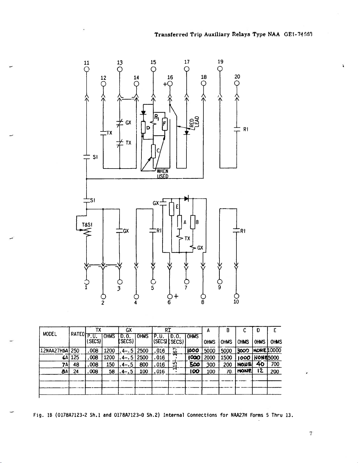
Fig.
(0178A7123-2
lB
A
7A48
8A
RATED
250
125
-
24
TX
s—ij--—
jj-
(SECS)
.008
1200
1200
.
008
)O815O.4-
.008
Sh.1
and
CX
jy-
SECS)
.4-.5
.
4—.52500
58
.4—.
0178A7123-O
9
0
10
jjj
2500
800
100
5
Sh.2)
(SEC
.016
.
016
16
.016
i5-j—
SECS)
Internal
IGOO
f
Connections
RI
lj-
A
OHMS OHMS
5000
2000 1500
p2OOt4O4O
100
100
B
5000
70.
for
C
OHMS OHMS
3
1000
tiO3E
NAA27H
Forms5Thru
B
4ORt
NON’
12.
E
OFLS
0000
O00
700
200
13.
Page 8

GEI-74663
Truisferred
Trip
Auxiliary
Pclavs
Type
NAA
I
‘Si’
,19
‘T
20
I
Li
I.
C
Li
2
-
)4ODXL
----—----
1aiizia
25QQ
ATD
J
P.U.
(ILJ4S
0.0.
.
(SC’,
—
—
QL-.
HNS
(scs
1
flOQ
P.11.
SECS
—
.15LiO
19
A
12.5
.008
_L
*
Fig.
1C
(0195A4933
Sh.1
141
and
LJ_
0195A4933
Sh.?
121)
8
J
I
D.C.
(sECs
0CO
Irernai
6
I
*iMS
1000
8
—-
A
—
CO
2G00
Connections
oios
—
cOO
5
?_
1500
for
c
0I14S
000
LL4_
1000
14AA27H
*
0104S
0N
NONE
Forms
-
D
E
lI
—
0OC
—
F
)HMS
—1
VCZD
2
5000
15
and
Up.
Page 9
13
Q
Transferred
Trip
Auxiliary
Relays
Type
NAA
GE-74’P3
TTY
i*1
TTY
_[TTY
I
IBX
6
E
MUF
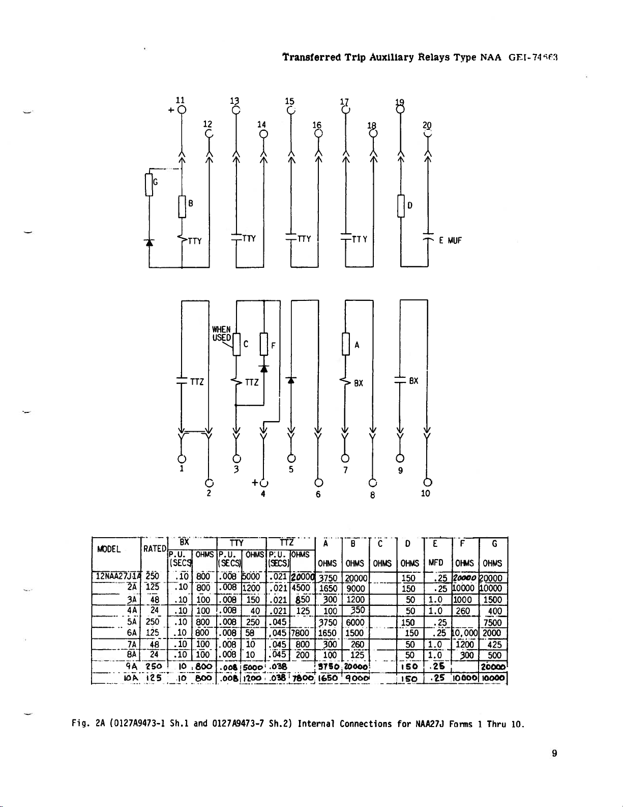
Fig.
DEL
12NAA27J1
24
34
44
5A
64
74
84
9
iO
2A
(0127A9473-1
RATE[’I
5
-U_.
250
125
48
24
250
125
48
24
?S0
1Z5
BX
(SEC
.10
.10
.10
.10
.10
.
10
.10
.10
10
10
Sh.1
OHMS
800
800
100
100
800
BOO
100
100
800
,00
and
0127A9473-7
TTY
P-U.
CS)
(SE
.008
.008
.008
.008
.008
.008
.008
.008
.a05OOo
oo
OHMS
5000
1200
150
40
250
58
10
10
P:u.
(CS)
021
021
.021
.021
.045
.045
.045
.045
.Y
Sh.2)
TTZ
OHMS
2OOO
4500
850
125
7800
800
200
00
Internal
A
OHMS
OHMS OHMS
20000
1650
9000
1200
300
100
6000
3750
1650
1500150
300
100
750.?OOoo;
Connections
B
350
260
125
Zio
D
E
C
MFD
OHMS
150
150
1.0
50
1.0
50
150
50
1.0
1.0
50
5O
for
NAA27J
F
OI*4S
2ooc’.’
25
10000
.25
1000
260
.25
.25
0,000
1200
300
2
Forms1Thru
G
OHMS
0000
0000
10O
400
7500
2000
425
500
20000
10.
9
Page 10

GEI-746E53
Transferred
.1
Trip
Auxiliary
A
•1
A
Relays
A
1’
Type
I
NAA
A
A
A
1
ftJF
MODEL
hA
12A
13A
14A
-
RATF.fl
125
25O
125
.±L.
p.’j.
(SEC)
1
.10
fl
.10
L
OHMS
800
800
800
EJ
p.U.
(SEC.)
.008
008
.008
.008
OHMS
1200.016
5000
1200
L
rn
Pu.
(SEC)
.021
4
OHMS
4500
2
4500
850
A
OHMS
1650
iTW
1650
6
OHMS
9000
9000
1200
L
B
C
D
OHMS
OHMS
150
iSO
50
E
OF
.25
.25
F
OHMS
10000
10000
1000
G
H
J
OHMS
10000
0
20000
10000
1500
075
LW
OHMS
2.0
100
2.0
100
50
10
Fi4.
_
?3
(0J78A9042-2
zz
Sh.1
and
017$1U042—O
zt
Sh,2)
Intrni
Connections
for
NAA27J
Forms
11
and
Up.
Page 11

TX
Transferred
Trip
Auxiliary
Relays
Type
GX
NAA
CFT-74(
63
F—--—.
MODEL
LI2NAA2K1A
-—
-
--.
_.
4A1
—.
—
2A
RATED
250
125
.
4b
2i1
.
.—
2
P-U.
(SECS
•
•
.008
.008.
4
TX
006
008
OHMS
12CC
1200
150
56
4
D.C.
(SEcs
h
45
.4—-h
GX
OHMS
2500
2500
800
100
A
OHMS
5000
2000
300
100
T
B
OHMS
5000
1500
200
70
8
C
OHMS
7500
5000
1000
200
jo
Fjq.
3A
(0L7A9474—1
Sh.1
and
fll27A9474—1
Sh.2)
Internal
Connections
for
NAA27K
Forms
Thru
1
13.
11
Page 12

GEI-74663
Transferred
Trip
Auxiliary
Relays
Type
NAA
O5MFD
‘TX
GX
TX
L
2
4
6
8
MODEL
L
12
12NAA27K16A
--
12NAA27K17A
Fig.
1’)
27K15A
-
3B
(0195A4967—O
RATE:
250
125
F
143
P.11.
(sECS)
.008
.C08
.C0
-___
Sb.1
TX
and
OHMS
12CC
]20Cf
IC
-—
0195A4%-Q
D.C.
(sEcs)
.4—.5
.L
——
4—
Sh.2’)
.5
.
OX___
OHMS
2500
250C
-—--
CC
Internal
A
OHMS
5000
2000
300
Connections
OHMS
5000
1500
t
-___
B
200
for
OHMS
7500
5000
1000
NM27K
C
Forms
15
and
Up.
Page 13

-3
Cl)CDCD
1
(0
tlD
-3
(0
2
C—’
rr
C--
-
->>-----
F—-----
-3•
_L
I
—
I
-.---J
.-‘----l---
I
.
oo
-
no
r’
L.
--S
+
-
-
-
4j
4
1,
-
h——
-l
LI
-
--
Z,
E
4__L
-1---,----t-
i__._
CD
.
-3
-3
CD
-3
0
C-,
CD
LI,
0
-3
r)
CD
-S
CD-
-3
---
,-
.—--3
-
•
_--
n—.—
1’
U,
-3
I-!
C-)
IC‘DC-)
C-C
-3-
Page 14

________
-i
t:i
0
-3
-
jI
(D
>:
>>—
H
!
L
I)
H
LI
4
:
I,,
H
If
L’
M-*.-*;
1
T
-9;’
ztrj
0
cc
cc
cc
—
C,
Page 15

Transferred
Trip
Auxiliary
ZD
LZAD
Relays
Type
NAA
GEI-74663
Fg.
4C
O195A493O-O
r
12NAA27L21A1
_
ZZZ
Shi
22A_.
21L
and
.--.L-.-.-L-_
15,000
QQQ.
LI
1.500
-p..-
0195A4930-2
3C0NQIQ
1000.
200
-
t0
-.
-4-.
Sh.2)
_
-______________
Interna’
10.C00j.fl(.
-
51H
I4’-.i
kOOO
Connections
-H
for
NAA27L
Forms
21
Thru
23.
15
Page 16
GEI-74663
Transferred
Trip
Auxiliary
Relays
Type
NAA
L}
7A27i?’.
IL
72NM7I.5.#
29A
30A
-4,k
3
4
SSA
*.
30A
25
Z
Z
7A
28A
29A
27
250
13.5
i2
250
‘L
250
125
4-8
250
,e5
125
48
sj
£08
iii.
.203
.03&
.OQ8iZk
•,Z
fis.
.o°8
.008
I2oO
.008
.008
-
L..
LQ00
4.
300
5000
Z000
300
200
IS
.100_
&.
20a
o00
J50O
200
4-6
.45
.t.5
.
4...f
4-•
.40S
40.
455
-r-
J
ii
3k
!
NoW
3000
1000
—
Lcs
‘$
‘.Sw
.2
2.SLOI
2.5K
8X
4500
2500
O0
a_
L...
L
a_
AL€
-03L
.OI(J
.O/(t.
0.OI.
0J
40
—
—
4-0
I
J
0
1Q00
1Q00
500
121
-.003.,
•±
•fi
.3E
002..
002
.Dc
fi.cak
1
l900
jj
1.7k
1&
r
...
A0.
Q..
4.(L3
i&
-
700
10.000
5000
700
f&
5
50K
toK
2’
—
—
—
—
K
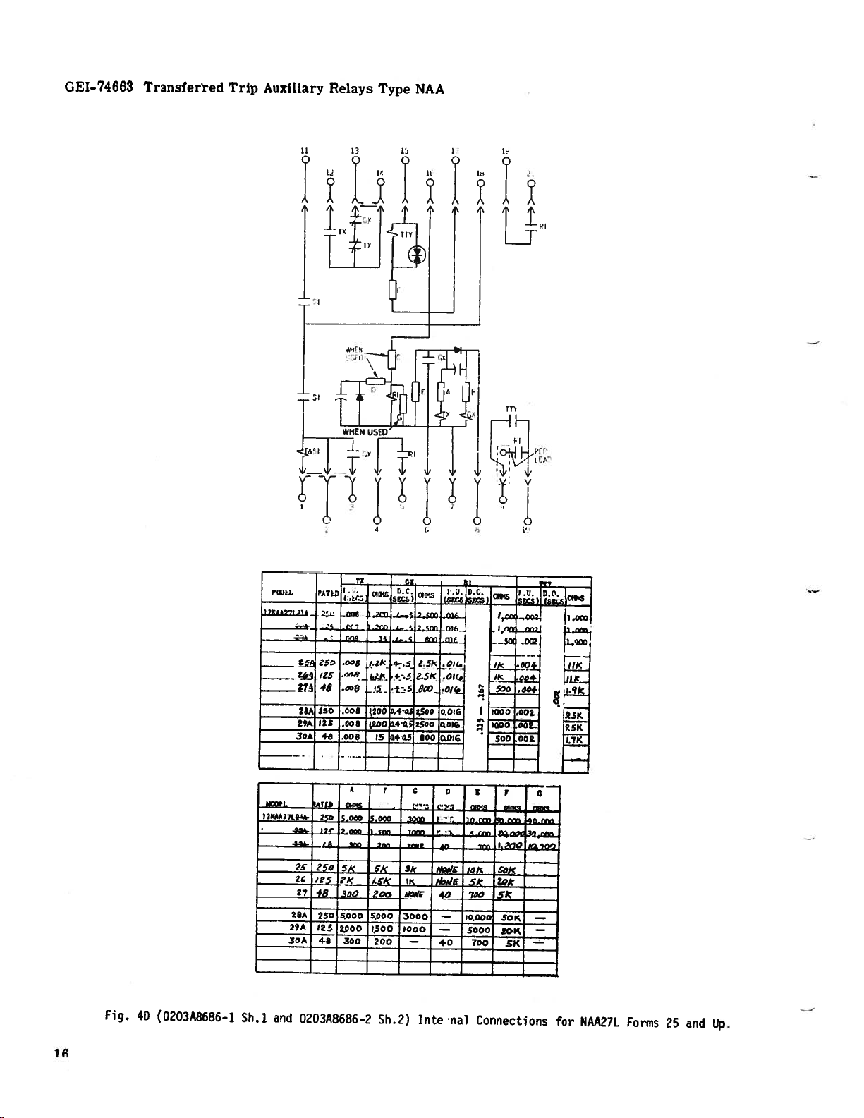
Fig.
4D
(0203A8686—1
Sh.l
and
0203A8686-2
Sh.2)
Intenal
Connections
for
NAA27L
Forms
25
and
lip.
Page 17
Transferrrci
Trip
Auxiliary
Relays
Type
NAA
CF
[-,74t3
HEE,.
LND
OPERAUNG
I
ARM
STOP
CONTACTS
FRAME
ARMATURE
POLE
PIECE
ARM
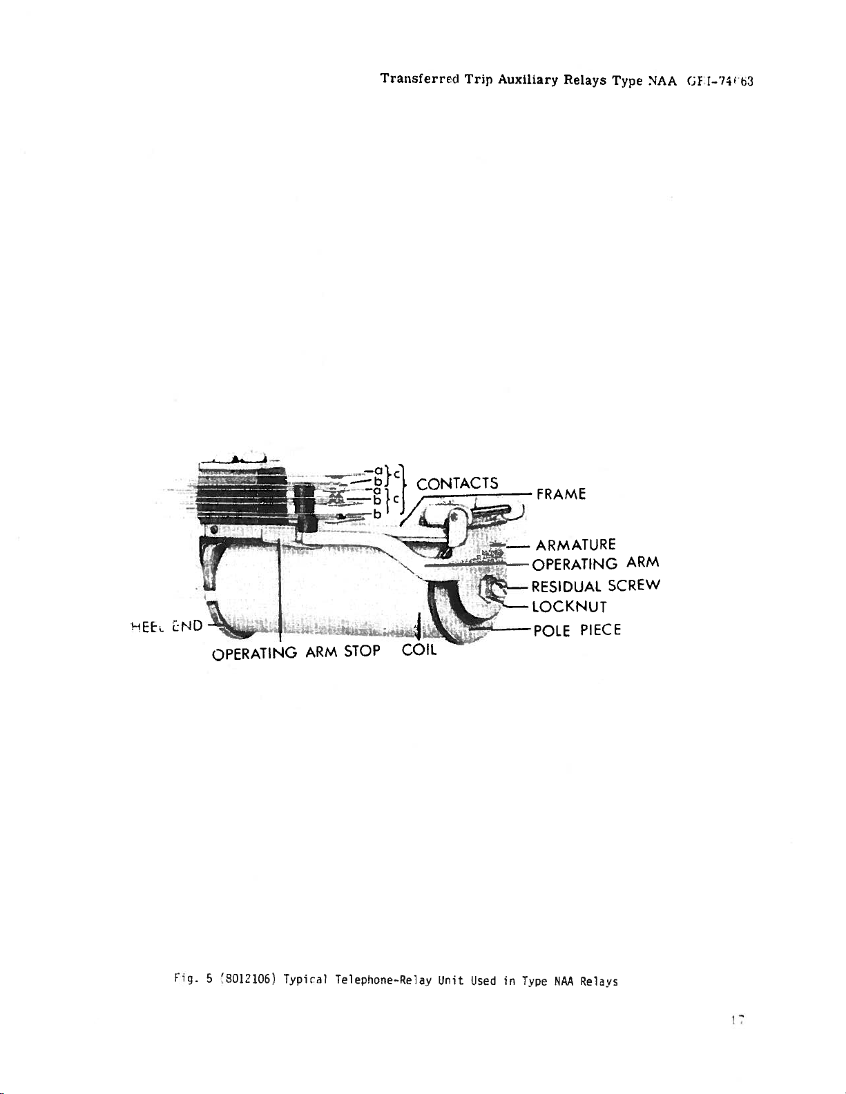
fig.
S
‘8O121O5
Typ1r1
Telephone—Relay
Unit
Used
in
Type
NAA
Relays
Page 18

GEI-74663
Transferred
Trip
Auxiliary
Relays
Type
NAA
9,125
232MM
/
4
I
4
HOLES
5MM
DRILL
6.625
168MM
GLASS
1
.
125
29MM
PANEL
SEMI—FLUSH
MTO
4)
MTG.
6.
157
4
06
12MM
LOCATION
10-32
X
SCREWS
187
MM
5/8
2
15M
3/8
DRILL
HOLES
II
STUDS
1
0-32
5/16—18
SURFfCE
8.
21
CUTOUT
DRILLED
STUDS
MTG.
NUMDER
97531
00000
00000
10
8
BACK
MAY
1.
156
29MM
STUD
1
4
6
VIEW
REPLACE
HOLES
NO
2
4
3
121MM
18
5MM
FUR
TYPICAL
INCHES
MM
CUTJUT
1
72MM
1
5.687
144MM
PANEL
DRILLING
SEMI--FLUSH
FRONT
DIM.
F
ig.
(6209271
6
MOUNTING
VIEW
843
VIEW
r,
r
ur’
r
8
8.
223MM
C
SC
SHOWING
fl
1
A
I
ur’r
-
and
112
r
L
5.25
133MM
3/4
DRILL
10
1-IDLES
9MM
1
FOR
PANEL
SURFACE
DRILLING
FRONT
5/16-18
it
‘-i
D
n
ii
Dijraiii
for
STUD
NAA27K
Relays
.500
12MM
I
(TYPICA)
MOUNTING
VIEW
18
Page 19

‘Frwfeirec
Trip
Auxiliary
Relays
Type
4AA
CEJ-741,
3
261MM
1/4
DRILL
6
625
168MM
PANEL
SEMI-FLUSH
MTG.
4)
MTG.
LOCATION
10—32
SCREWS
157MM
SURFACE
iI
X
3/8
0-32
TUBS
(2)
/FOR
00000
10
CUTOUTS
DRILLED
5/16—18
SURFACE
17
19
00000
00000
20
18
STUD
NUMBER
97531
00000
8
BACK
MAY
-
15
16
14
I
6
4
VIEW
REPLACE
HOLES
123MM
STUDS
MTG.
13
11
12
NO
2
5
562
42MM
5MM
TYPICAL
INCHES
MM
FOF
*
-
FIG.
-----
CU1IUT
5
1414MM
PANEL
DRILLING
SEMI-FLUSH
FRONT
DIM.
7
(6209272
.
687
MOUNTING
VIEW
VIEW
(ii)
Outline
FOR
254MM
.218
SHOWING
SURFACE
Panel
and
ASSEMBLY
MTG.
Drilling
3,0
76MM
ON
Diagram
3/4
20
OF
STEEL
for
NAA27H,
DRLL
HOLES
15MM
5/16-18
HARDWARE
PANELS
NAA27J
PANEL
FOR
STUD
and
HAA27L
DRILLING
SURFACE
FRONT
Relays
.500
1
2MM
(TYPICAL)
MOUNTING
VIEW
75
9
247MM
Indicates
Ik’ision
19
Page 20

GE
Power
215
Anderson
Markham,
Canada
Tel:
(905)
Fax:
www.ge.comlindsyslpm
Management
Ontario
L6E
1B3
294-6222
(905)
201-2098
Avenue
 Loading...