

Page 1
Corporate Offices
SerVision Ltd.
USA:
MVS-
4
4
I
I
N
N
S
STT
A
ALLLL
A
ATTII
O
O
N
N
I
I
N
N
S
STT
R
R
U
U
C
CTTII
O
O
N
N
S
S
11 Hartom St, Jerusalem 91450, Israel PO 434, Milford, NJ 08848, USA
Tel: + 972-2-535-0000, Fax: + 972-2-586-8683 Tel: +1-908-995-4383 Fax: +1-888-681-8218
E-mail: info@servision.net www.servision.net E-mail: maxe@servision.net
Page 2

IVG-400 Installation Instructions
Contents
Introduction ........................................................... 1
Connection Diagram ............................................... 1
Hardware Requirements......................................... 1
Selecting a Location ............................................... 2
Power Connection and Usage ................................. 2
Installing the IVG-400............................................ 3
Connecting a Camera.............................................. 4
Connecting a Sensor............................................... 4
Connecting an Alarm .............................................. 5
Connecting an Alarm in Release 1................................5
Connecting an Alarm in Release 2................................6
Copyright
Copyright © 2005 All Rights Reserved.
Page 3
Introduction
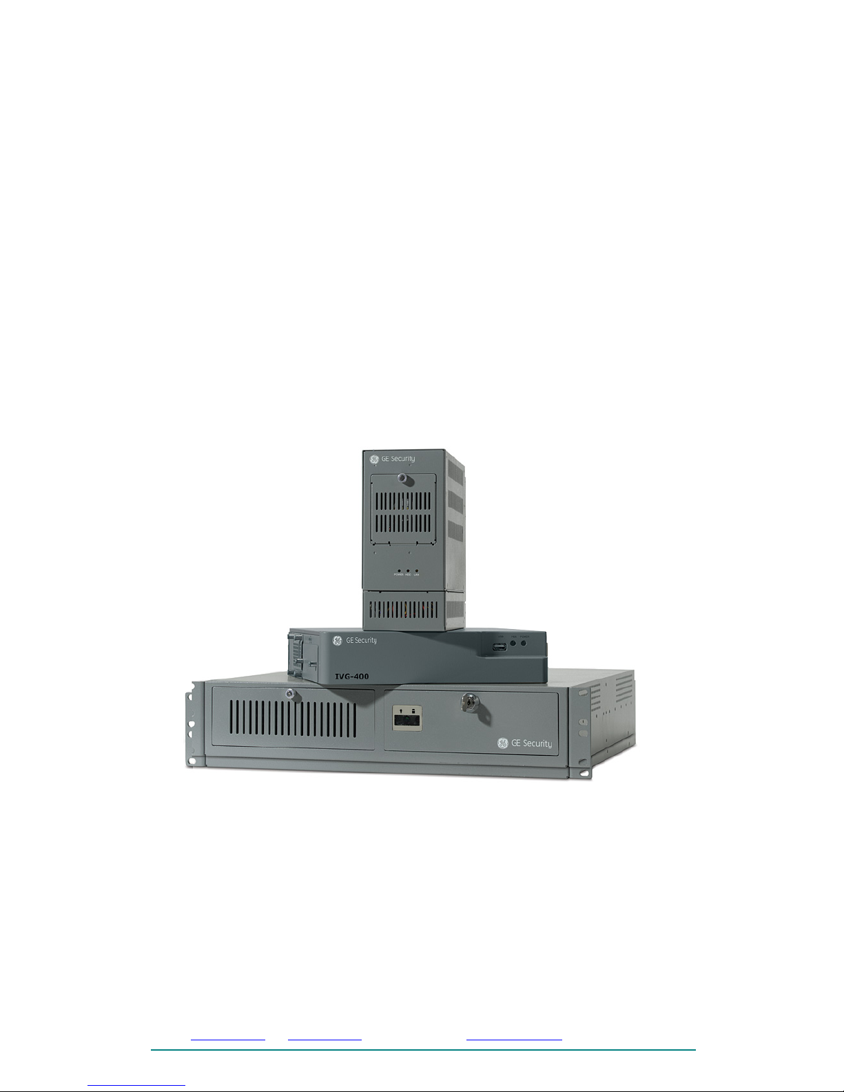
The SerVision IVG-400 is a mobile DVR that is designed to be installed in
vehicles. Up to four cameras, six input sensors, and two activators can be
connected to the IVG-400. Once connected, these devices can be monitored and
controlled remotely through the IVG-400.
This document explains how to install the IVG-400 in a vehicle.
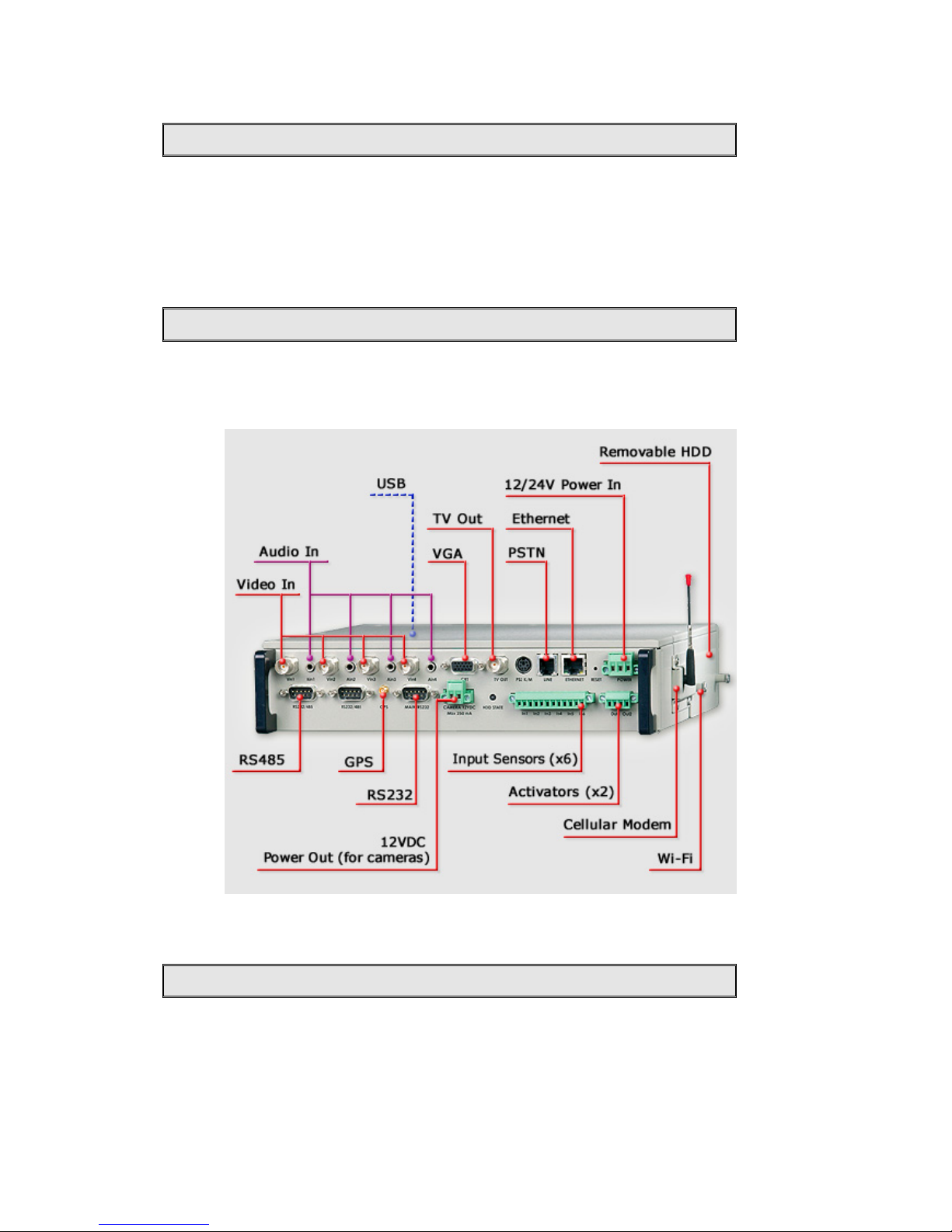
Connection Diagram
The following diagram indicates where the various connectors are located on the
IVG-400 unit.
Figure 1 - Connection diagram
Hardware Requirements
The following hardware is included with the IVG-400:
1. Two side supports
2. Six screws to attach the side supports to the unit
IVG-400 Installation Instructions
Page 1 of 7
Page 4

Selecting a Location
The following additional hardware is required to install the IVG-400 and connect
cameras to it:
1. Screws to connect the unit to its anchoring surface
2. Cellular modem
3. 16 AWG red and black cable to connect the unit to the vehicle battery
4. Coax cable to connect the camera to the IVG-400
Additional hardware is required for the following
optional features:
IVG-400 Installation Instructions
Page 2 of 7
he
1. Camera control:
• Flat ribbon cable with D-type 9-pin
female connector (Pin 6-TX positive,
Pin 7-TX negative)
Figure 2 - Flat ribbon
cable with D-type 9-pin
female connector
2. Connecting a sensor:
• Two wires to connect the output to t
IVG-400 dry contacts (normally
included with the sensor)
3. Connecting an alarm:
• 16 AWG red and black cable to connect the
alarm to the IVG-400, and, for release 1,
to a relay
• For release 1: A 12VDC power relay, such
as the Fujitsu FTR-MYAA012A
Figure 3 – Fujitsu FTRMYAA012A relay
Selecting a Location
IVG-400 should be placed in the coolest available location in the driver’s cabin of
the vehicle. Some options are:
• Under a seat
• Immediately below the ceiling
• Beside the driver’s seat, under the window
Power Connection and Usage
The IVG-400 draws its power from the vehicle battery. Its current consumption
is 1.5AMP at 12V DC or 0.75AMP at 24V DC.
The IVG-400 can be connected to the vehicle battery in one of two ways:
• Directly
• Through the ignition switch
Page 5

Installing the IVG-400
If the IVG-400 is connected directly to the vehicle battery, it continues operating
even when the engine is turned off. For example, with a 55AMP/h battery, the
system will continue to function for about 10 hours if the vehicle battery is not
recharged.
If the IVG-400 is connected through the ignition switch, it will only operate when
the ignition is on. Bear in mind, also, that it will take a few minutes for the IVG400 to boot up after the ignition is switched on and about 2.5 minutes after the
ignition is switched off.
Installing the IVG-400
To install the IVG-400:
1. Connect the two side supports (Figure 4) to either side of the body of the
IVG-400, using three screws for each support, as in Figure 5. (The screws
are included with the IVG-400.)
Figure 4 - Side support
Figure 5 - Side supports attached to IVG-400 body
Screw
Side support
IVG-400 body
(upside down)
2. Place the unit in the desired location and attach it securely by connecting
the side supports to the anchoring surface with two or three screws on
each side. (These screws are not included with the IVG-400.)
IVG-400 Installation Instructions
Page 3 of 7
Page 6

Connecting a Camera
Note: The unit can be placed horizontally or vertically. If it is placed
vertically, the modem side must face up.
Figure 6 - Attaching the Unit
Modem
Side support
Anchoring
surface
3. Connect the system to the vehicle battery using the
PowerIn connector
(see
Figure 1, page 1):
• Connect the red wire to the positive (+) connector
• Connect the black wire to the negative (-) connector
• Connect wire to the car ignition
Note: For additional information, see “
Power Connection and Usage,”
page 2.
4. Insert a cellular modem in one of the PCMCIA slots in the modem
compartment (see
Figure 1, page 1).
Note: Either the upper or lower slot can be used.
* Important note:
Do not power off the system without supplying a
signal that informs about it (e.g. switching off the ignition)
Connecting a Camera
Up to four cameras can be connected to the IVG-400. To connect a camera to
the unit:
1. Install the camera in its desired location in the vehicle.
2. Connect the video output of the camera to a
VideoIn connector on the
rear panel of the IVG-400 (see
Figure 1, page 1).
3. Optional: If the camera has remote control features (pan, tilt, and/or
zoom), these can be activated by connecting the camera controller to an
RS232/485 connector on the rear panel of the IVG-400 (see
Figure 1,
page 1) using a D-type 9-pin female connector (
Figure 2, page 1).
Connecting a Sensor
Up to six input sensors can be connected to the IVG-400. To connect a sensor to
the unit:
1. Install the sensor in its desired location in the vehicle.
IVG-400 Installation Instructions
Page 4 of 7
Page 7

Connecting an Alarm
2. Connect the two contacts of the sensor to the
Sensors terminal block on
the rear panel of the IVG-400 (see
Figure 1, page 1), as illustrated in
Figure 7.
Note: The wires must be connected to two adjacent contacts in the same
group (e.g., the two contacts of “In1”), but the polarity does not matter.
Figure 7 – Connecting a sensor
Sensor
IVG-400
rear panel
In1 In2 In3 In4 In5 In6
Sensors
terminal
b
lock
Connecting an Alarm
Up to two alarms and other devices that are activated in response to detected
events can be connected to the IVG-400. Essentially, the IVG-400 functions as
an on/off switch for these devices.
A power relay is required for the alarm to be connected to the IVG-400 properly.
Release 1 of the IVG-400 does not have a built-in relay. To connect an alarm to a
release 1 unit, you must acquire a relay and connect it externally. In release 2 of
the IVG-400, the relay is built into the unit. Instruct ions for connecting an alarm,
with or without a built-in relay, are provided below.
Connecting an Alarm in Release 1
To connect an alarm to a release-1 unit, which does not have a built-in relay,
follow the instructions below.
Note: The connections are illustrated in Figure 9 below. See
Figure 1, page 1, for
a diagram of the IVG-400 rear panel, including the locations of the
12VDC
Power Out
connector and the Activators terminal block.
1. Acquire a 12VDC power relay, such as the Fujitsu FTR-MYAA012A.
2. Install the alarm in its desired location in the vehicle.
3. Connect the right (+) contact of the
12VDC Power Out connector to
Relay/1.
IVG-400 Installation Instructions
Page 5 of 7
Page 8

Connecting an Alarm
4. Connect
Relay/2 to the positive contact of an output connection (e.g.,
“Out1”) in the
Activators terminal block.
5. Connect
Relay/3 to the alarm.
6. Connect the other side of the alarm to the positive (+) power.
7. Connect the negative (-) power
Relay/4.
8. Connect
Relay/4 to the right (-) contact of the output connection (e.g.,
“Out1”) in the
Activators terminal block.
9. Connect the left (-) contact of the
12VDC Power Out connector to the
same right (-) contact of the output connection (e.g., “Out1”) in the
Activators terminal block.
Figure 8 – Connecting an alarm to the IVG-400, release 1
IVG-400 Installation Instructions
Page 6 of 7
Connecting an Alarm in Release 2
To connect an alarm to a release-2 unit, which has a built-in relay:
1. Install the alarm in its desired location in the vehicle.
2. Connect the alarm to the
Activators terminal block on the rear panel of
the IVG-400 (see
Figure 1, page 1) as follows (see Figure 9):
• Connect the positive (+) power to the alarm.
Alarm
+
12V Power
-
Out1 Out2
+ - + - + -
12VDC
Power Out
12VDC
1
Relay
2 4
3
IVG-400
rear panel
Activators
terminal block
Page 9

Connecting an Alarm
IVG-400 Installation Instructions
Page 7 of 7
contact (+) of an output
• act (-) of the same
• Connect the other side of the alarm to the left
connection (e.g., “Out1”) in the terminal block.
Connect the negative (-) power to the right cont
output connection in the terminal block.
Figure 9 – Connecting an alarm to the IVG-400, release 2
Out1 Out2
Activators
+ - + -
+
12V er
Alarm
Pow
-
IVG-400
rear panel
terminal block
 Loading...