

GE MVAD007MV2AA, MVAD009MV2AA, MVAD012MV2AA, MVAD018MV2AA, MVAD024MV2AA Installation Instructions Manual
Page 1
Installation Instructions
Plenum, Slim Duct Models
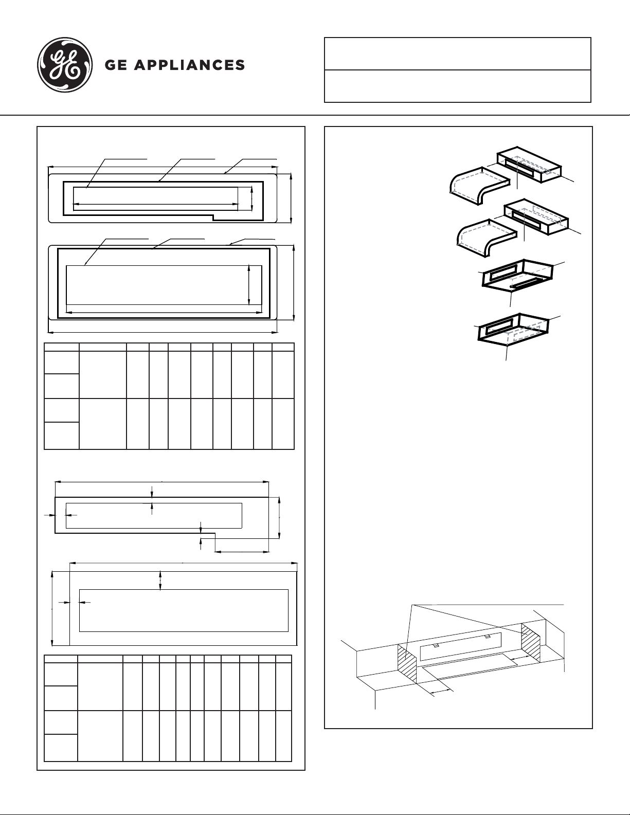
1. Dimensions
Ceiling opening
A
F
H
C
7-1/2
35
(190)
(890)
7-1/2
47-5/8
(190)
(1210)
11-1/2
(291)
11-1/2
(291)
3-1/2
(90)
3-1/2
(90)
25-1/4
(640)6 (152)
37-3/4
(960)6 (152)
Supply
PAD0890SA
Return
PAD0890RA
Supply
PAD1210SA
Return
PAD1210RA
Supply air outlet
Model A B C D E F G H
AD07SL2VH*
AD09SL2VH*
AD12SL2VH*
MVAD007MV2AA
MVAD009MV2AA
MVAD012MV2AA
AD18SL2VH*
MVAD018MV2AA
MVAD024MV2AA
35
(890)
47-5/8
(1210)
2. Rough Opening Dimensions:
A
E
Plenum opening
E
Plenum opening Return air inlet Ceiling opening
G
29-7/8
(760)
42-1/2
(1080)
3. Typical Configurations
Supply and return down
B
Supply down, return rear
D
Supply side, return down
Supply side, return rear
NOTES:
Maintain 36” (915 mm) between supply outlet and return inlet for floor and ceiling locations.
If the supply outlet and the return inlet are on a common wall, one must be 36” (915 mm) higher than the
other.
All duct longitude and latitude joints must be sealed.
Duct insulation values should meet local code requirements.
F
H
Supply
PAD0890SA
Return
PAD0890RA
Supply
PAD1210SA
Return
PAD1210RA
D
C
G
I
J
Model A B C D E F G H I J
AD07SL2VH*
AD09SL2VH*
AD12SL2VH*
MVAD007MV2AA
MVAD009MV2AA
MVAD012MV2AA
AD18SL2VH*
MVAD018MV2AA
MVAD024MV2AA
30-1/2
(776)
43-1/8
(1096)
5-7/8
(150)
5-7/8
(150)
7-5/8
(194)
7-5/8
(194)
3/4
(20)
3/4
(20)
7/8
(21)
7/8
(21)
1-5/8
(40)
1-5/8
(40)
32-1/4
(820)
44-7/8
(1140)
10-1/4
(260)
10-1/4
(260)
2-3/8
(60)
2-3/8
(60)
B
1-1/4
(31)
1-1/4
(31)
The cabinet of the Slim Duct unit must be insulated if
installed in a non-conditioned space.
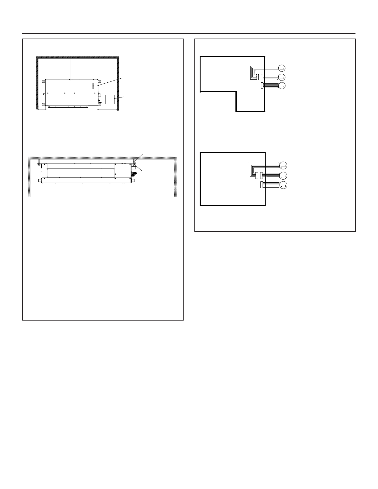
4. Set the Blocking in the Ceiling to Protect the Indoor Unit
The inside of two sides of the celing must
be sealed.
001
002
31-5000441 Rev. 0 09-19 GEA
Page 2
Installation Instructions
M
M
M
CN16CN15
CN14
SWING MOTOR-UP/DOWN
SWING MOTOR-UP/DOWN
SWING MOTOR-LEFT/RIGHT
INDOOR UNIT PCB
M
M
M
CN11-1
SWING MOTOR-UP/DOWN
SWING MOTOR-UP/DOWN
SWING MOTOR-LEFT/RIGHT
INDOOR UNIT PCB
CN11
CN35
5. Minimum Clearances
0001>
39-3/8
electrical box
accessing opening
>100
If the unit location is not readily accessible, provide a 24”
X 24” (610 mm X 610 mm) service access panel per local
code.
Installation
A B
Install the unit level to the building structure, using 3/8”
threaded rods, washers, and nuts.
If a gravity drain is preferred, slope the cabinet 1/4”
toward the drain end.
4 qty. 3/8 hanging bolts
16 qty
3/8 nuts
8 qty
3/8 washer
7. Swing Motor Wiring, FlexFit Models
Connect up/down swing motors to CN15 and CN16.
The left/right swing motor goes to CN14.
8. Swing Motor Wiring, MRV-S Models
Connect up/down swing motors to CN11 and CN11-1.
The left/right swing motor goes to CN35
6. Connecting Plenum to Indoor Unit
A. Direct Connection
Use M4x3/8 sheet metal screws. Holes on the panel will
match the holes on the unit.
B. Connection to Ducts
Use the holes in the panel and the unit to attach the
ductwork. Use M4x3/8 screws. All ducts must be sealed
and insulated.
2
31-5000441 Rev. 0 09-19 GEA
Page 3

Instructions d’installation
Modèles à plénum, conduits étroits
1. Dimensions
Supply
PAD0890SA
Return
PAD0890RA
Supply
PAD1210SA
Return
PAD1210RA
Sortie d’air fourni
Ouverture du plafond
A
F
H
C
Modèle A B C D E F G H
AD07SL2VH*
AD09SL2VH*
AD12SL2VH*
MVAD007MV2AA
MVAD009MV2AA
MVAD012MV2AA
AD18SL2VH*
MVAD018MV2AA
MVAD024MV2AA
35
(890)
47-5/8
(1210)
7-1/2
(190)
7-1/2
(190)
35
(890)
47-5/8
(1210)
11-1/2
(291)
11-1/2
(291)
Ouverture du plénum
E
Ouverture du plénum Entrée d’air repris Ouverture du plafond
G
3-1/2
25-1/4
(90)
(640)6 (152)
3-1/2
37-3/4
(90)
(960)6 (152)
2. Dimensions d’ouvertures brutes:
A
E
B
D
29-7/8
(760)
42-1/2
(1080)
3. Configurations typiques
Air fourni et repris
dans le bas
Air fourni dans le bas,
air repris en arrière
Air fourni sur le côté,
air repris dans le bas
Air fourni sur le côté,
air repris en arrière
REMARQUES:
Gardez 36 po (915 mm) entre la sortie d’air fourni et
l’entrée d’air repris pour les emplacements de plancher
et de plafond.
Si la sortie d’air fourni et l’entrée d’air repris se trouvent
sur le même mur, l’un des deux doit être 36 po (915
mm) plus haut que l’autre.
Tous les joints de longitude et de latitude des conduits
doivent être scellés.
F
H
Supply
PAD0890SA
Return
PAD0890RA
Supply
PAD1210SA
Return
PAD1210RA
D
C
G
I
J
Modèle A B C D E F G H I J
AD07SL2VH*
AD09SL2VH*
AD12SL2VH*
MVAD007MV2AA
MVAD009MV2AA
MVAD012MV2AA
AD18SL2VH*
MVAD018MV2AA
MVAD024MV2AA
30-1/2
(776)
43-1/8
(1096)
5-7/8
(150)
5-7/8
(150)
7-5/8
(194)
7-5/8
(194)
3/4
(20)
3/4
(20)
7/8
(21)
7/8
(21)
1-5/8
(40)
1-5/8
(40)
32-1/4
(820)
44-7/8
(1140)
10-1/4
(260)
10-1/4
(260)
2-3/8
(60)
2-3/8
(60)
B
1-1/4
(31)
1-1/4
(31)
Les valeurs d’isolation des conduits doivent satisfaire
les exigences du code local.
L’enceinte du conduit étroit doit être isolée dans un
espace non conditionné.
4. Construire le blocage dans le plafond
pour protéger l’unité intérieure
L’intérieur des deux côtés du plafond
doit être scellé.
001
002
31-5000441 Rev. 0 09-19 GEA
Page 4

Instructions d’installation
M
M
M
CN16CN15
CN14
MOTEUR OSCILLANT - HAUT/BAS
MOTEUR OSCILLANT - HAUT/BAS
MOTEUR OSCILLANT - GAUCHE/DROITE
CARTE DE CIRCUIT
UNITÉ INTÉRIEURE
M
M
M
CN11-1
MOTEUR OSCILLANT - HAUT/BAS
MOTEUR OSCILLANT - HAUT/BAS
MOTEUR OSCILLANT - GAUCHE/DROITE
CARTE DE CIRCUIT
UNITÉ INTÉRIEURE
CN11
CN35
5. Dégagements minimaux
0001>
39-3/8
Boîte électrique
Orifice d’accès
>100
Si l’emplacement de l’unité n’est pas aisément accessible,
fournissez un panneau d’accès de service de 24 x 24 po
(610 mm x 610 mm) conforme au code local.
Installation
A B
Installez l’unité de niveau avec la structure du bâtiment,
à l’aide de tiges filetées 3/8 po et leurs rondelles et
écrous.
Si une évacuation par gravité est préférée, inclinez
l’enceinte de 1/4 po vers l’extrémité de l’évacuation.
Boulons de suspension 3/8 (4)
Écrou 3/8
(16)
Rondelle
3/8 (8)
7. Câblage du moteur oscillant,
modèles FlexFit
Connecter les moteurs haut/bas à CN15 et CN16. Le
moteur gauche/droite va à CN14.
8. Câblage du moteur oscillant,
modèles MRV-S
Connecter les moteurs haut/bas à CN11 et CN11-1. Le
moteur oscillant gauche/droite va à CN35.
6. Connexion du plénum à l’unité
intérieure
A. Connexion directe
Utilisez des vis à tôle M4 x 3/8. Les trous sur le pan-
neau vont correspondre à ceux de l’unité.
B. Connexion aux conduits
Utilisez les trous du panneau et de l’unité pour fixer les
conduits. Utilisez des vis M4 x 3/8. Tous les conduits
doivent être scellés et isolés.
2
31-5000441 Rev. 0 09-19 GEA
 Loading...