

GE
Digital Energy
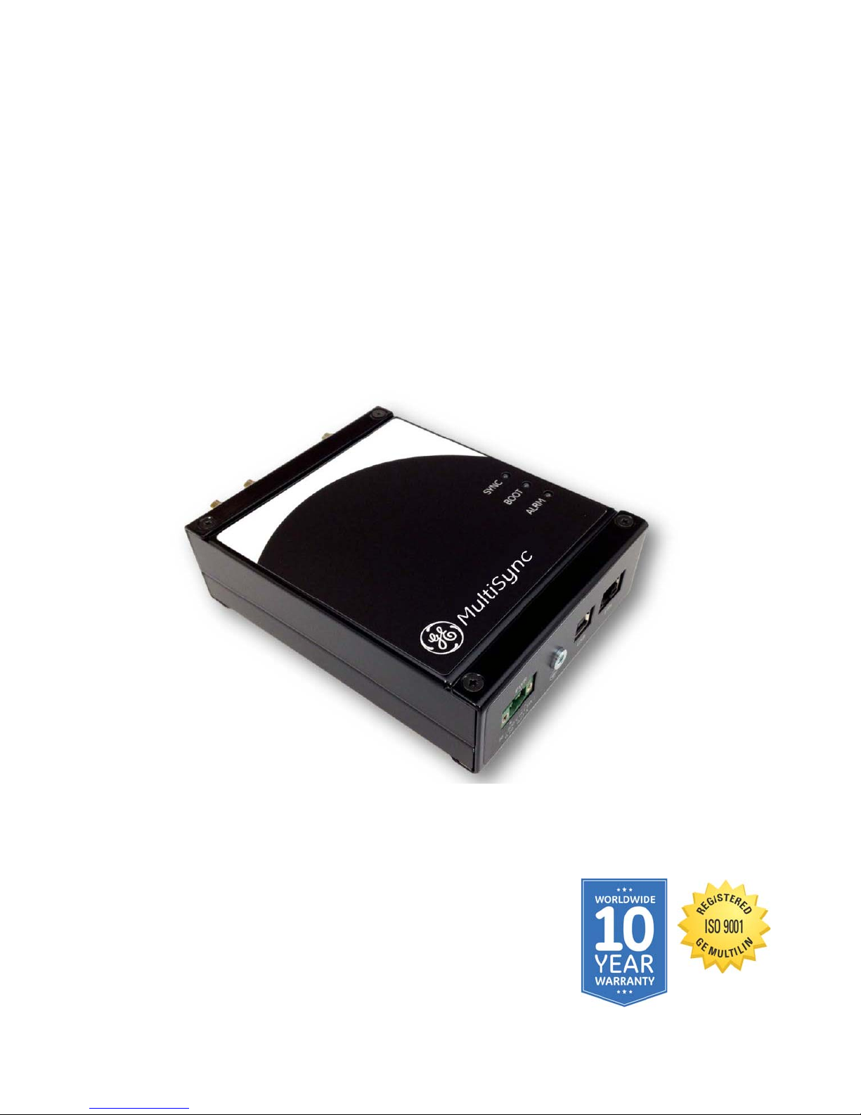
MultiSync 100
1588 GPS Clock
Instruction Manual
Revision: 1.0x
Manual P/N: 1601-0300-A1
Manual Order Code: GEK-119628
1601-0300-A1

Copyright © 2014 GE Multilin Inc. All rights reserved.
GE Multilin MultiSync 100 GPS Clock Instruction Manual for version 1.0x.
MultiSync 100 GPS Clock, EnerVista, Digital Energy, Multilin, and GE Multilin are trademarks
or registered trademarks of GE Multilin Inc.
The contents of this manual are the property of GE Multilin Inc. This documentation is
furnished on license and may not be reproduced in whole or in part without the permission
of GE Multilin. The content of this manual is for informational use only and is subject to
change without notice.
Part number: 1601-0300-A1 (March 2014)
General safety precautions
Before attempting to install or use the device, review all safety indicators in this document
to help prevent injury, equipment damage, or downtime.
Failure to observe and follow the instructions provided in the equipment manual(s)
could cause irreversible damage to the equipment and could lead to property damage,
personal injury and/or death.
Before attempting to use the equipment, it is important that all danger and caution
indicators are reviewed.
If the equipment is used in a manner not specified by the manufacturer or functions
abnormally, proceed with caution. Otherwise, the protection provided by the
equipment may be impaired and can result in Impaired operation and injury.
Caution: Hazardous voltages can cause shock, burns or death.
Installation/service personnel must be familiar with general device test practices,
electrical awareness and safety precautions must be followed.
Before performing visual inspections, tests, or periodic maintenance on this device or
associated circuits, isolate or disconnect all hazardous live circuits and sources of
electric power.
Failure to shut equipment off prior to removing the power connections could expose
you to dangerous voltages causing injury or death.
All recommended equipment that should be grounded and must have a reliable and
un-compromised grounding path for safety purposes, protection against
electromagnetic interference and proper device operation.
In addition to the safety precautions mentioned all electrical connections made must
respect the applicable local jurisdiction electrical code.
Utrustning som är kopplad till skyddsjord via jordat vägguttag och/eller via annan
utrustning och samtidigt är kopplad till kabel-TV nät kan i vissa fall medfõra risk fõr brand.
Fõr att undvika detta skall vid anslutning av utrustningen till kabel-TV nät galvanisk
isolator finnas mellan utrustningen och kabel-TV nätet.

Safety words and definitions
The following safety and equipment symbols are used in this document.
Indicates a hazardous situation which, if not avoided, will result in death or serious
injury.
Indicates a hazardous situation which, if not avoided, could result in death or serious
injury.
Indicates a hazardous situation which, if not avoided, could result in minor or
moderate injury.
Indicates practices not related to personal injury.
For further assistance
For product support, contact the information and call center as follows:
GE Digital Energy
650 Markland Street
Markham, Ontario
Canada L6C 0M1
Worldwide telephone: +1 905 927 7070
Europe/Middle East/Africa telephone: +34 94 485 88 54
North America toll-free: 1 800 547 8629
Fax: +1 905 927 5098
Worldwide e-mail: multilin.tech@ge.com
Europe e-mail: multilin.tech.euro@ge.com
Website: http://www.gedigitalenergy.com/multilin


MultiSync 100 GPS Clock
Table of contents
General safety precautions.......................................................................................... ii
Safety words and definitions....................................................................................... iii
For further assistance .................................................................................................. iii
1PRODUCT
DESCRIPTION
2 THEORY OF
OPERATION
Product description........................................................................................................ 1
Features..............................................................................................................................................................1
Order codes .....................................................................................................................2
Specifications..................................................................................................................2
Accuracy.............................................................................................................................................................2
Electrical .............................................................................................................................................................2
Output options.................................................................................................................................................3
Networking........................................................................................................................................................3
Environmental specifications ...................................................................................................................3
Mechanical specifications ..........................................................................................................................4
Antenna requirements.................................................................................................................................4
Testing and certification .............................................................................................................................5
GPS and precise time synchronization.......................................................................7
The IRIG-B Time Code Standard...................................................................................8
Modulated IRIG-B ...........................................................................................................................................9
Unmodulated IRIG-B .....................................................................................................................................9
IEEE-1344 Extensions ................................................................................................................................10
Defining IRIG-B Time Codes....................................................................................................................10
IRIG-B in the MultiSync 100 1588 GPS Clock .................................................................................. 11
IRIG-B wiring considerations..................................................................................................................12
Network Time Protocol / Simple Network Time Protocol..........................................................12
SNTP................................................................................................................................................................... 12
NTP/SNTP in the MultiSync 100.............................................................................................................13
IEEE 1588 / PTP / C37.238............................................................................................13
Message-Based Synchronization ........................................................................................................ 13
Components of a 1588 Network.......................................................................................................... 14
C37.238 ............................................................................................................................................................ 16
1588 and C37.238 in the MultiSync 100...........................................................................................16
MULTISYNC 100 GPS CLOCK – INSTRUCTION MANUAL v

TABLE OF CONTENTS
3 INSTALLATION Device hardware ..........................................................................................................19
Front panel......................................................................................................................................................19
Bottom panel .................................................................................................................................................20
Top panel .........................................................................................................................................................20
Install hardware ...........................................................................................................20
Install GE Configuration Tool software ....................................................................21
4 INTERFACES Front panel interface ...................................................................................................23
LED Indicators................................................................................................................................................23
GE Clock Configuration Tool software interface ....................................................23
Quick configuration.....................................................................................................................................24
Save clock configuration to a file .........................................................................................................26
Load clock configuration from a file ...................................................................................................26
Top menu buttons .......................................................................................................................................26
Configure clock settings..............................................................................................27
Set Local Standard Time (LST) and daylight savings time ........................................................28
Configure I/O settings .................................................................................................29
Configure output port settings ..............................................................................................................30
Set output sync reporting ........................................................................................................................31
Enable relay alarms ....................................................................................................................................32
Configure network settings........................................................................................33
Change basic network settings.............................................................................................................33
Change NTP settings ..................................................................................................................................35
Change IEEE 1588 / C37.238 PTP settings........................................................................................36
Change SNMP settings ..............................................................................................................................37
Set notifications ............................................................................................................................................38
Configure maintenance settings ...............................................................................39
Apply maintenance overrides ................................................................................................................39
Set software login banner........................................................................................................................40
Reset the MultiSync 100 GPS Clock to factory defaults .............................................................40
Add an NTP or PTP license .......................................................................................................................40
Configure user settings...............................................................................................41
Add a user group..........................................................................................................................................41
Add a user .......................................................................................................................................................42
Delete a user ..................................................................................................................................................42
Delete a user group ....................................................................................................................................43
Reset a user password ..............................................................................................................................43
Configure access control settings.............................................................................44
Configure GPS settings................................................................................................46
Change GPS parameters..........................................................................................................................46
Reset the GPS.................................................................................................................................................46
View GPS coverage .....................................................................................................................................47
vi MULTISYNC 100 GPS CLOCK – INSTRUCTION MANUAL

MultiSync 100 GPS Clock
Chapter 1: Product description
Product description
This chapter outlines the product, order codes, and specifications.
Product description
The MultiSync 100 GPS Clock provides sub-microsecond accuracy for synchronizing
intelligent electronic devices, and is available with 1588 timing. Configuration options
include adjustable hold-over times in cases of poor GPS coverage, and compensation for
installation parameters such as antenna cable length.
Features
Features of the MultiSync 100 include:
• DC IRIG-B (Unmodulated, DCLS - C37.118)
• User defined pulses
• Modified Manchester
• NTP/ SNTP (IEC 61850)
• IEEE 1588-2011 (Supports Power Profile - C37.238)
• SNMP v1, v2c & v3
•DCF-77
• Isolated power supply
• HIgh power line drivers
• Low noise due to balanced pair distribution
• UTC and LST, with user-defined DST options
• Remote configuration
• Password protection and user authentication
MULTISYNC 100 GPS CLOCK – INSTRUCTION MANUAL 1

ORDER CODES CHAPTER 1: PRODUCT DESCRIPTION
NOTE
MultiSync100 P MultiSync GPS Clock with 1588 timing
Accessories
GPS Antenna GPS Antenna
GPS CNT-240 * Antenna cable
15 15 m
30 30 m
60 60 m
Antenna Mount Kit Antenna Mount Kit
Lightning Protection Kit Lightning Protection Kit
Order codes
This section lists the order codes for the MultiSync 100.
Order codes are subject to change without notice. See the ordering page at
store.gedigitalenergy.com for the latest options.
Table 1: Order codes
Specifications
Specifications are subject to change without notice.
Accuracy
Timing accuracy:................................................ <= 100 ns to UTC
Drift: ..........................................................................<= 100
Electrical
POWER SUPPLY
Voltage: ...................................................................36 to 300 VDC
Power drain:.......................................................... 5 W max
ISOLATION
Power to antenna:.............................................. 3.75 kV
Power to I/O: ......................................................... 3.75 kV
INPUTS
RJ45 UTP connector:......................................... 10/100 Mbps
USB2.0: ....................................................................Type B
OUTPUTS
Sync indication output:....................................200 V, 150 mA (max)
2 x TTL outputs: ...................................................T ime codes or pulses or user defined
µs over 5 hours (7 ppb)
Electrical specification: TTL/CMOS compatible
0-5 V, 150 mA sink/source
Timing accuracy: ≤100 ns to UTC
2 MULTISYNC 100 GPS CLOCK – INSTRUCTION MANUAL

CHAPTER 1: PRODUCT DESCRIPTION SPECIFICATIONS
Output options
TTL
Programmable pulses: .....................................From 1000 per second to 1 per day with programmable
offset & duration
DCF-77:....................................................................DC level shift
Local or universal time
IRIG-B:.......................................................................DC level shift or Modified Manchester
IEEE 1344 extensions (C37.118)
AFNOR NF S87-500 extensions
Local or universal time
Networking
GENERAL
DHCP:........................................................................Auto-configuration with fallback to ARP tested link-local
address
VLAN: ........................................................................packet tagging
PTP (IEEE 1588 V2)
General: ...................................................................One-step or two-step operation
End-to-end or peer-to-peer delay calculations
Layer 2 (Ethernet) or Layer 3 (UDP) transport
Slave only mode
Default Profile support
Power Profile support: ......................................C37.238
TLV support:...........................................................C37.238 offset from TAI time base used by PTP
Alternate Time Offset TLV support: ............with automatic or manual offset
SNMP MIB support:.............................................C37.238
NTP
General: ...................................................................Stratum-1 NTP & SNTP time server
Multicast & Broadcast server capability
Optional MD5 authentication
SNMP
General: ...................................................................V1, V2C, and V3 support, independently enabled
Configurable V1 and V2C community names and security
groups
Fully configurable via SNMP
V3 User-based Security Module (USM) support
USM MIB support
USM authentication methods:......................MD5, SHA
USM privacy methods:......................................DES, AES
NOTIFICATIONS
General: ...................................................................SNMP trap generation V1, V2C, and V3
SNMPv3 traps authenticated and privatized via USM
Syslog (RFC-3164 and 5424 verities)
Environmental specifications
OPERATING ENVIRONMENT
Ambient Temperature: .....................................-40° to 140 °F (-40° to 60 °C) for UL 60950 and Component
Storage Temperature:.......................................-40° to 185 °F (-40° to 85 °C)
Ambient Relative Humidity:............................5% to 95% (non-condensing)
Altitude:....................................................................Up to 6560 feet (2000 m)
MULTISYNC 100 GPS CLOCK – INSTRUCTION MANUAL 3
Parts
-40° to 195 °F (-40° to 85 °C) for IEC 60068 Type Test short
term rating
SPECIFICATIONS CHAPTER 1: PRODUCT DESCRIPTION
Pollution Degree:................................................. 2
Conformal Coating (humidity protection)
optional:............................................................. Request quote
OTHER ENVIRONMENTAL
Humidity (non-condensing): ..........................to 95%
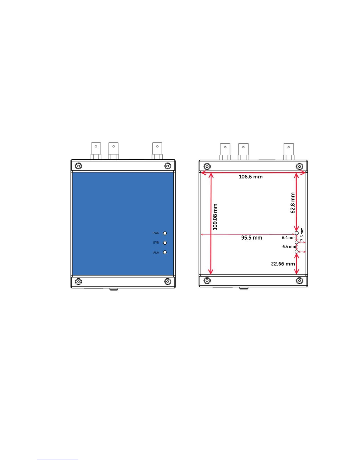
MECHANICAL PROPERTIES
Dimensions (H × W × D): ..................................45 × 110 × 155 mm
Weight: ....................................................................0.42 kg
Installation:............................................................
Metal DIN rail-mountable case with IP30
(Ingress Protection rating)
Mechanical specifications
Antenna requirements
ANTENNA PORT SPECIFICATIONS
Voltage: ...................................................................5 VDC
Current:.................................................................... 100 mA (max)
Input impedance: ...............................................50
Total gain:............................................................... The total combined gain of the antenna system (antenna,
4 MULTISYNC 100 GPS CLOCK – INSTRUCTION MANUAL
Ω
cable, and connectors) should fall in the range of 10 to 35 dB,
the optimum being 22 dB.

CHAPTER 1: PRODUCT DESCRIPTION SPECIFICATIONS
Testing and certification
APPROVALS AND CERTIFICATION
Compliance Applicable council directive According to
CE compliance Low voltage directive EN60950-1
EMC directive EN61000-6-2
North America cULus UL60950-1
ISO Manufactured under a registered
quality program
IEC 61850-3 EMI TYPE TESTS
EN61000-6-4
C22.2 No. 60950-1
CB Report including all country deviations
ISO 9001:2008
Test Description Test Levels Severity
IEC 61000-4-2 ESD Enclosure Contact +/- 8 kV 4
Enclosure Air +/- 15 kV 4
IEC 61000-4-3 Radiated RFI Enclosure Ports 20 V/m
IEC 61000-4-4 Burst D.C. Power port +/-4 kV 4
IEC 61000-4-5 Surge Signal Ports +/- 4kV line to earth,
D.C. Power Ports +/- 2kV line to earth,
IEC 61000-4-6 Induced RFI Signal Ports 10 V 3
D.C Power ports 10 V 3
Earth Ground
Ports
IEC 61000-4-8 Magnetic Field Enclosure Ports 40 A/m continuous,
IEC 61000-4-29
IEC 61000-4-11
IEC 61000-4-12 Damped Oscillatory Signal Ports
IEC 61000-4-16 Mains Frequency
IEC 61000-4-17 Ripple on D.C. Power
IEC 60255-5 Dielectric Strength Signal Ports 2 kVAC
IEC 60255-5 H.V. Impulse Signal Ports 5 kV (fail-safe relay output)
Voltage Dips and
Interrupts
Voltage
Supply
D.C. Power ports 30% for 0.1s, 60% for 0.1s,
D.C. Power ports
Signal Ports
D.C. Power ports
D.C. Power ports 10% 3
D.C. Power ports 2 kVAC
+/- 2kV line to line
+/- 1kV line to line
10 V 3
1000A/m for 1s
100% for 0.05s
2.5kV common, 1kV diff,
mode @1MHz
30V Continuous,
300V for 1s
(fail-safe relay output)
Levels
4
3
3
4
MULTISYNC 100 GPS CLOCK – INSTRUCTION MANUAL 5

SPECIFICATIONS CHAPTER 1: PRODUCT DESCRIPTION
IEEE 1613 (37.90.X) EMI IMMUNITY TYPE TESTS
Test Description Test Levels
IEEE 37.90.3 ESD Enclosure Contact +/-2 kV, +/-4 kV, +/- 8 kV
Enclosure Air +/-4 kV, +/-8 kV, +/- 15 kV
IEEE 37.90.2 Radiated RFI Enclosure Ports 35 V/m
IEEE 37.90.1 Fast Transient Signal Ports +/-4 kV @2.5kHz
D.C. Power Ports +/-4 kV
IEEE 37.90.1 Oscillatory Signal Ports 2.5kV common mode
D.C Power ports 2.5 kV common, 1 kV diff.
IEEE 37.90 H.V. Impulse Signal Ports 5 kV (fail-safe relay output)
D.C. Power ports 5 kV
IEEE 37.90 Dielectric Strength Signal Ports 2 kVAC
D.C. Power ports 2 kVAC
@1MHz
mode @1MHz
ENVIRONMENTAL TYPE TESTS
Test Description Test Levels
IEC 60068-2-1 Cold Temperature Test Ad -40°C, 16 hours
IEC 60068-2-2 Dry Heat Test Bd +85°C, 16 hours
IEC 60068-2-30 Humidity (Damp Heat,
Cyclic)
IEC 60255-21-1 Vibration 2 g at 10-150 Hz
IEC 60255-21-2 Shock 30 g @ 11 mS
Test Db 95% (non-condensing),
55°C, 6 cycles
6 MULTISYNC 100 GPS CLOCK – INSTRUCTION MANUAL

MultiSync 100 GPS Clock
Chapter 2: Theory of operation
Theory of operation
GPS and precise time synchronization
The Global Positioning System (GPS) is a satellite-based navigation system that is used as
the master time source for clock timing signals published by the MultiSync 100 GPS Clock.
Each satellite contains an atomic clock, and each satellite publishes a navigation
message, including the clock time, at six second intervals via a spread spectrum carrier.
The atomic clocks in GPS satellites are monitored by ground control systems to ensure
accuracy, and the location of a GPS receiver on the ground is essentially determined by
measuring the time delay between time signals from multiple satellites. Since precise time
synchronization is required for determining the location of a GPS receiver, GPS can also be
used for precise time synchronization around the Earth. To understand how GPS can be
used for precise time synchronization, some definitions are necessary.
• Time - the marking of an event with respect to a reference origin. GPS time signals,
based on the atomic clock in GPS satellites, are the reference origin.
• Time interval - a measurement of duration between events.
• Coordinated Universal Time (UTC) - a time system adopted in 1972. UTC is based on
the weighted combination of atomic clocks located around the world. UTC
occasionally changes by the addition of leap seconds.
• Frequency - the measure of the number of events that occur within a time interval,
such as the number of oscillations of a voltage waveform within one second
Power system applications require precise time synchronization for sequences of event
logs, fault recordings, and wide area protection systems based on synchrophasors. Precise
time requires precise time intervals, as measured by the time between periodic pulse
edges or waveform zero-crossings. The relationship between these marks and a reference
time is a measure of the phase of the signal. One application requirement for precise time
synchronization is the definition of the required phase stability for time intervals specific to
the application.
The most restrictive accuracy in power systems is that of synchrophasors, with a required
accuracy of 1 microsecond. GPS clock receivers are capable of time tagging events to the
100-nanosecond level and maintaining that accuracy over periods ranging from seconds
to years. Typical small pulse-to-pulse jitter (phase noise) on the order of one nanosecond
will not impact accuracy, but it is required that the time intervals maintain long-term phase
MULTISYNC 100 GPS CLOCK – INSTRUCTION MANUAL 7

THE IRIG-B TIME CODE STANDARD CHAPTER 2: THEORY OF OPERATION
stability. GPS is capable of global time and frequency dissemination 24 hours a day, with
timing accuracies in the 100-nanosecond range. This level of accuracy explains why GPS
has become the typical time synchronization method for commercial applications.
GPS time is not identical to UTC (or civil) time, but is related to UTC time. One major
difference is that GPS time is a continuous time usually measured in weeks and seconds
from the GPS time zero point of midnight, January 6, 1980. The other difference is leap
seconds. UTC time is an atomic time, is the basis for civil time, and aims to keep the
difference between UTC time and the earth's rotational speed to less than 0.90 seconds. As
the earth's rotation slows down, it becomes necessary to correct UTC time by adding a
leap second. GPS time is not adjusted by leap seconds, and as of 2014, GPS time is 16
seconds ahead of UTC time. Beyond the integer number of leap seconds, GPS time is tightly
controlled to within one microsecond of UTC, with the difference reported in the GPS
navigation message to a precision of 90 nanoseconds.
A GPS receiver gains GPS time by locking on to the spread spectrum carrier and decoding
the 50-Hz datastream containing the navigation message. The total signal path
transmission delay computation begins with the range from the satellite to the receiver.
One can convert the range to a time delay using the speed of light. This delay is then
corrected for the ionospheric delay (using a model provided in the navigation message), for
the effect of transmission in a rotating inertial reference system, and for hardware delays
in cables and receiver circuitry. The difference between the computed and measured
millisecond time marks gives the relationship between the receiver clock and GPS time.
Once the relationship between the receiver clock and GPS time is established, time signals
can be produced by the receiver. Synchronization between receivers at different locations
can be established and maintained using GPS time. If time signals are required to maintain
synchronization with UTC, the UTC correction in the navigation message can be applied,
and time signals, such as one-pulse-per-second (1PPS) signals of IRIG-B or IEEE 1588
signals, can be set and maintained to UTC.
The accuracy of GPS time signals is related to the ability of the receiver to accurately track
the received navigation code. Accuracies in the 100-nanosecond range are possible with
undegraded GPS signals and correct receiver position.
The IRIG-B Time Code Standard
IRIG-B is one of several time code formats defined under the IRIG Standard. The IRIG-B time
code standard was developed by the U.S. Army through the Inter-Range Instrumentation
Group (IRIG). IRIG-B defines a frame time of 1000 milliseconds, a frame rate of 1 Hz or 1
pulse per second (PPS), a bit time (or pulse time) of 10 milliseconds, and 100 bits per frame
(or 100 PPS).
IRIG-B is an analog signal: analog pulses (or bits) represent time in fractions of seconds
from midnight, and days from January 1st . The length of the pulse, as a percentage of the
pulse time of 10 milliseconds, determines if the bit is a logical 0, a logical 1, or a position
identifier. As the bit rate implies, the IRIG-B time code format publishes 100 bits per second
in a specific order to represent the time, the date, time changes, and the time quality. The
presence of 2 consecutive position identifiers signifies the start of a time frame. The first
identifier alerts that the next rising edge is the frame marker. As IRIG-B has a 1000
millisecond frame interval, this rising edge marker is the "1 PPS" time synchronization
commonly referred to.
A significant part of the 100 bits in an IRIG-B frame are Binary Coded Data (BCD) that
defines the actual time. The BCD time-of-year (BCDTOY) indicates seconds, minutes, and
hours from midnight, recycling daily, and days from January 1st, recycling yearly. The BCD
8 MULTISYNC 100 GPS CLOCK – INSTRUCTION MANUAL
CHAPTER 2: THEORY OF OPERATION THE IRIG-B TIME CODE STANDARD
year code (BCDYEAR) counts years and cycles to the next year on January 1st. There is also
an optional Straight Binary Seconds (SBS) code that counts seconds from midnight,
recycling daily.
There are three methods of communicating analog pulses in the IRIG Standard:
• Modulated (amplitude-modulated, sine wave carrier) - the method supported in older
IEDs
• Unmodulated (DC level shift, no carrier signal) - the most commonly supported
method for new IEDs
• Modified Manchester (amplitude-modulated, square wave carrier) - a version not
described in this manual.
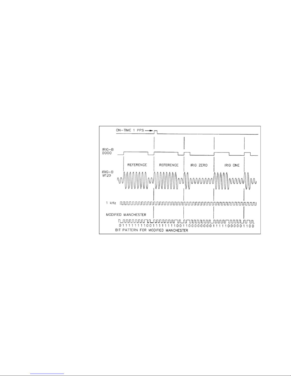
The figure shows the pulses for the three methods. The top row (IRIG-B B000) is
unmodulated, the middle row (IRIG-B B120) is modulated, and the bottom row is Modified
Manchester.
Figure 1: Methods of communicating analog pulses, IRIG Standard 200-04
Modulated IRIG-B
A modulated IRIG-B clock continuously produces a sine wave signal with the amplitude of
the signal modulated to indicate the value of a specific bit. The length of the modulation
determines a logical 0, logical 1, or position identifier. Modulated, or amplitude-modulated
(AM) IRIG-B is the original method for distributing IRIG-B time codes. New IEDs generally
don't support amplitude-modulated time codes, as other methods of producing IRIG-B
signals are more accurate. The advantage to AM is that there can be longer cable runs
between the clock and subscribing IEDs than with other methods. AM implementations
generally use coaxial or shielded twisted pair cables and BNC connectors.
Unmodulated IRIG-B
Unmodulated IRIG-B is also known as DC Level Shift (DCLS). An IRIG-B clock using DCLS
only produces an output to produce a pulse, and the pulse is a constant magnitude. The
length of the output determines a logical 0, logical 1, or position identifier. The output value
MULTISYNC 100 GPS CLOCK – INSTRUCTION MANUAL 9

THE IRIG-B TIME CODE STANDARD CHAPTER 2: THEORY OF OPERATION
is normally 5V for on, and 0V for off. Newer IEDs typically use DCLS due to accuracy.
However, the distance to IEDs is limited to around 100m. DCLS typically uses TTL outputs
over shielded, twisted pair cable and BNC connectors.
IEEE-1344 Extensions
The original IRIG Standard did not provide year information, or BCDYEAR, in the time code:
only time and day from the start of the year. Lack of year data was a limitation for some
applications, especially in regards to synchrophasors. The IEEE 1344-1995 Standard for
Synchrophasors for Power Systems includes definitions to include year data in the IRIG-B
time code. The IEEE 1344 extensions, as they're commonly known, add calendar year, leap
second, daylight savings time, local time offset, and time quality to the IRIG-B signal.
Individual devices may or may not support the IEEE 1344 extensions.
The IRIG-B Standard was revised in 2004 to include year data. The 200-04 Standard allows
IRIG-B to publish BCDYEAR, as described. The IEEE 1344 Standard has been replaced by
C37.118-2005 IEEE Standard for Synchrophasors for Power Systems, although the term
"IEEE 1344 extensions" is still in common use. The term "C37.118 extensions" may be used
instead.
Defining IRIG-B Time Codes
The IRIG Standard further defines the Time Code Designation to completely describe the
published time code signal.
Table 2–1: IRIG signal identification numbers (3 digits)
Format A | | | IRIG-A Format
B | | | IRIG-B Format
D | | | IRIG-D Format
E | | | IRIG-E Format
G | | | IRIG-G Format
H | | | IRIG-H Format
1st Digit - Modulation 0 | | Unmodulated - DC Level Shift, pulse-width coded
1 | | Amplitude modulated, sine wave carrier
2 | | Manchester modified
2nd Digit - Carrier Frequency /
Resolution
3rd Digit - Coded Expressions 0 BCD
0 | No carrier (DCLS)
1 | 100 Hz / 10 ms resolution
2 | 1 kHz / 1 ms resolution
, CF, SBS
, CF
, SBS
, BCD
YEAR,
, BCD
YEAR,
, BCD
YEAR
, BCD
YEAR
μs resolution
μs resolution
CF, SBS
CF
, SBS
3 | 10 kHz / 100
4 | 100 kHz / 10
1 BCD
2 BCD
3 BCD
4 BCD
5 BCD
6 BCD
7 BCD
TOY
TOY
TOY
TOY
TOY
TOY
TOY
TOY
Common time code formats are:
• B00x for DC Level Shift
• B12x for amplitude modulated
10 MULTISYNC 100 GPS CLOCK – INSTRUCTION MANUAL

CHAPTER 2: THEORY OF OPERATION THE IRIG-B TIME CODE STANDARD
With the IEEE 1344 extensions OFF (no BCD
) these time codes are B002 and B122; with
YEAR
the IEEE 1344 extensions ON, these codes are BOO6 and B126. These time codes are
defined by the clock settings as well as the ability of IEDs connected to the clock to support
these implementations. A limitation of IRIG is that there can be only one time code on any
clock connection string.
IRIG-B in the MultiSync 100 1588 GPS Clock
The MultiSync 100 has two TTL (coaxial) output ports, each of which can be configured to
provide an IRIG-B time signal, independent of the other port. The MultiSync 100 supports
both DC Level Shift and Modified Manchester time codes. The complete time code
designations supported are:
• B002: DC Level Shift, only BCD
On the GE Configuration tool I/O tab:
–Under IRIG-B / Pulse Output Port select IRIG-B, and set Modulation to DCLS.
–Under IRIG-B Stream, set Extensions to None, and leave Binary code in seconds
unchecked.
• B006: DC Level Shift, BCD
TOY
On the GE Configuration tool I/O tab:
–Under IRIG-B / Pulse Output Port select IRIG-B, and set Modulation to DCLS.
–Under IRIG-B Stream, set Extensions to C37.118, and leave Binary code in
seconds unchecked.
• B007: DC Level Shift, BCD
TOY
On the GE Configuration tool I/O tab:
–Under IRIG-B / Pulse Output Port select IRIG-B, and set Modulation to DCLS.
–Under IRIG-B Stream, set Extensions to C37.118, and check Binary code in
seconds.
• B232: Modified Manchester, only BCD
On the GE Configuration tool I/O tab:
–Under IRIG-B / Pulse Output Port select IRIG-B, and set Modulation to Modified
Manchester.
–Under IRIG-B Stream, set Extensions to None, and leave Binary code in seconds
unchecked.
• B236: Modified Manchester, BCD
On the GE Configuration tool I/O tab:
–Under IRIG-B / Pulse Output Port select IRIG-B, and set Modulation to Modified
Manchester.
–Under IRIG-B Stream, set Extensions to C37.118, and leave Binary code in
seconds unchecked.
• B237: Modified Manchester, BCD
On the GE Configuration tool I/O tab:
–Under IRIG-B / Pulse Output Port select IRIG-B, and set Modulation to Modified
Manchester.
–Under IRIG-B Stream, set Extensions to C37.118, and check Binary code in
seconds.
in the time code.
TOY
and BCD
, BCD
YEAR
, and SBS in the time code.
YEAR
TOY
and BCD
TOY
, BCD
TOY
in the time code.
in the time code.
YEAR
, and SBS in the time code.
YEAR
in the time code.
MULTISYNC 100 GPS CLOCK – INSTRUCTION MANUAL 11
 Loading...