

Page 1
Digital Energy
Multilin
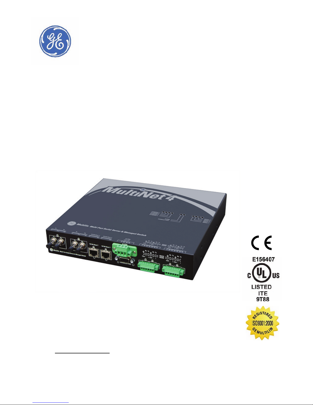
Multinet4 Multi-Port Serial
Server & Managed Switch
Instruction Manual
Manual P/N: 1601-9075-A1 (GEK-113502)
Copyright © 2008 GE Multilin
GE Multilin
215 Anderson Avenue, Markham, Ontario, Canada L6E 1B3
Tel: (905) 294-6222, 1-800-547-8629 (North America)
Fax: (905) 201-2098
Internet: http://www.GEmultilin.com
*1601-9075-A1*
GE Multilin's Quality Management
System is registered to
ISO9001:2000
QMI # 005094
UL # A3775
Page 2

© 2008 GE Multilin Incorporated. All rights reserved.
GE Multilin Multinet4 Serial Port Server & Managed Switch instruction manual.
Multinet4 Serial Port Server & Managed Switch, is a registered trademark of GE
Multilin Inc.
The contents of this manual are the property of GE Multilin Inc. This
documentation is furnished on license and may not be reproduced in whole or
in part without the permission of GE Multilin. The content of this manual is for
informational use only and is subject to change without notice.
Part numbers contained in this manual are subject to change without notice,
and should therefore be verified by GE Multilin before ordering.
Part number: 1601-9075-A1 (
September 2008)
Page 3

TABLE OF CONTENTS
Table of Contents
1: OVERVIEW CONFIGURATION .............................................................................................................................1-1
ONNECTIVITY ...................................................................................................................... 1-1
C
OWER AND GROUND ........................................................................................................ 1-2
P
NDICATORS ..........................................................................................................................1-2
I
OUNTING OPTIONS .......................................................................................................... 1-3
M
SPECIFICATIONS ............................................................................................................................... 1-4
HYSICAL .............................................................................................................................. 1-4
P
NVIRONMENTAL ................................................................................................................. 1-4
E
YPE TESTS ........................................................................................................................... 1-4
T
OWER REQUIREMENTS ...................................................................................................... 1-6
P
ORTS AND EXTERNAL CONNECTORS ..............................................................................1-7
P
NDICATORS ..........................................................................................................................1-7
I
PINOUTS .............................................................................................................................................. 1-9
RJ45 ..................................................................................................................................... 1-9
IBER OPTIC ......................................................................................................................... 1-9
F
EMALE) – CONSOLE PORT .....................................................................................1-10
DB9 (F
HOENIX CONNECTOR – ALARM PORT ............................................................................1-10
P
HOENIX CONNECTORS – SERIAL PORTS ........................................................................1-11
P
FEATURES AND BENEFITS ............................................................................................................ 1-12
ULTINET4 MULTI-PORT SERIAL SERVER & MANAGED SWITCH ................................ 1-12
M
EATURES SUMMARY .......................................................................................................... 1-13
F
2: GETTING STARTED INSTALLATION ................................................................................................................................... 2-1
OOLS ................................................................................................................................... 2-1
T
ITE SUITABILITY .................................................................................................................. 2-1
S
IRING AND GROUNDING GUIDELINES ........................................................................... 2-2
W
IBER OPTIC SAFETY ........................................................................................................... 2-2
F
IBER OPTIC HANDLING ..................................................................................................... 2-3
F
XTERNAL CONNECTIONS ..................................................................................................2-3
E
UNPACKING ....................................................................................................................................... 2-4
INSTALLATION OF THE MULTINET4 UNIT .............................................................................. 2-5
OUNTING ........................................................................................................................... 2-5
M
Mounting Hardware .................................................................................................2 - 5
Mounting in a 19” Rail System - General ........................................................2 - 5
Mounting in a 19” Rail System - Conventional Mounting .......................2 - 6
Mounting in a 19” Rail System - Reverse Mounting ..................................2 - 7
Mounting on a Panel ................................................................................................2 - 8
Mounting in a DIN Rail System ............................................................................2 - 10
CONNECTING FACILITY POWER ......................................................................................... 2-11
Making the Ground and Power Connections ...............................................2 - 11
CONNECTING TO THE CONSOLE PORT AND THE ALARM PORT .................................... 2-13
Console Port .................................................................................................................2 - 13
Alarm Port .....................................................................................................................2 - 13
CONNECTING NETWORK CABLES ...................................................................................... 2-13
Connecting Serial Cables .......................................................................................2 - 13
Connecting RJ45 Twisted Pair .............................................................................2 - 14
Connecting ST-type Fiber Optics (twist-lock) ................................................2 - 14
Connecting SC-type or LC-type Fiber Optics (snap-in) .............................2 - 15
MULTINET4 MULTI-PORT SERIAL SERVER & MANAGED SWITCH – INSTRUCTION MANUAL TOC–1
Page 4

TABLE OF CONTENTS
Connecting Single-mode Fiber Optics .............................................................2 - 15
MAINTENANCE .................................................................................................................................. 2-16
EMOVING THE MULTINET4 ...............................................................................................2-16
R
Disconnecting Power and Ground Lines ........................................................2 - 16
Disconnecting Network Cables ...........................................................................2 - 16
Packing the Multinet4 for Shipment .................................................................2 - 17
CLEANING FIBER OPTIC DEVICES ......................................................................................2-17
Cleaning Connectors ................................................................................................2 - 17
Cleaning Optical Ports .............................................................................................2 - 18
SOFTWARE MANAGEMENT .......................................................................................................... 2-19
ONFIGURING A NEW IP ADDRESS ..................................................................................2-19
C
THE ENERVISTA MULTINET4 SETUP SOFTWARE OVERVIEW ......................................... 2-22
THE ADVANCED SETTING - ADMINISTRATOR INTERFACE OVERVIEW ...................... 2-23
OGGING IN FOR THE FIRST TIME ..................................................................................... 2-23
L
DMINISTRATOR INTERFACE OVERVIEW ...........................................................................2-25
A
HE ADMINISTRATOR INTERFACE NAVIGATION TREE ..................................................... 2-28
T
3: ENERVISTA MULTINET4
SETUP SOFTWARE
4: SYSTEM
ADMINISTRATION
PC REQUIREMENTS .........................................................................................................................3-1
INSTALLATION .................................................................................................................................. 3-2
CONFIGURING ETHERNET COMMUNICATION ..................................................................... 3-3
USING THE QUICK CONNECT FEATURE .................................................................................3-6
CONNECTING TO THE MULTINET4 ........................................................................................... 3-7
PORT SETTING ................................................................................................................................... 3-8
ADVANCED SETTING ....................................................................................................................... 3-10
FIRMWARE UPGRADE ....................................................................................................................3-11
OFF-LINE FEATURE .......................................................................................................................... 3-12
EADING DEVICE SETTINGS ............................................................................................... 3-12
R
RITING SETTINGS TO A DEVICE ...................................................................................... 3-13
W
CONFIGURE A NEW IP ADDRESS THROUGH CONSOLE PORT ...................................... 3-14
VIRTUAL FRONT PANEL ................................................................................................................. 4-1
ADMINISTRATION TASKS .............................................................................................................. 4-2
YSTEM ................................................................................................................................. 4-2
S
YSTEM INFORMATION ........................................................................................................ 4-2
S
YSTEM STATUS ................................................................................................................... 4-3
S
IME ....................................................................................................................................... 4-4
T
Time: Time and Date ................................................................................................4 - 4
Time: Zone and DST ..................................................................................................4 - 5
Time: Persistence .......................................................................................................4 - 6
SNTP .................................................................................................................................... 4-7
SNTP: Global Settings ...............................................................................................4 - 7
SNTP: Servers ...............................................................................................................4 - 8
SNMP ................................................................................................................................... 4-9
SNMP: Global Settings .............................................................................................4 - 9
SNMP: Management Stations ..............................................................................4 - 11
SNMP: Trap Stations .................................................................................................4 - 12
SNMP: Users .................................................................................................................4 - 13
SNMP: Statistics ..........................................................................................................4 - 15
AUTHENTICATION ................................................................................................................. 4-19
Authentication: Policies ..........................................................................................4 - 19
Authentication: Accounts ......................................................................................4 - 22
Authentication: Files .................................................................................................4 - 24
SESSIONS .............................................................................................................................. 4-25
Sessions: Policies .......................................................................................................4 - 25
TOC–2 MULTINET4 MULTI-PORT SERIAL SERVER & MANAGED SWITCH – INSTRUCTION MANUAL
Page 5

TABLE OF CONTENTS
Sessions: Active Logins ...........................................................................................4 - 25
CHANGE PASSWORD ........................................................................................................... 4-26
OFTWARE UPGRADE ......................................................................................................... 4-27
S
ONFIGURATION .................................................................................................................. 4-31
C
Configuration: Files ...................................................................................................4 - 31
Configuration: Defaults ...........................................................................................4 - 32
SYSTEM REBOOT .................................................................................................................. 4-34
EVENTS TASKS ................................................................................................................................... 4-35
OGS ..................................................................................................................................... 4-35
L
Logs: Global Settings ................................................................................................4 - 40
Logs: Files ......................................................................................................................4 - 41
SYSLOG ................................................................................................................................. 4-42
Syslog: Global Settings ............................................................................................4 - 43
Syslog: Collectors .......................................................................................................4 - 43
ETHERNET TASKS ............................................................................................................................. 4-45
ORTS .................................................................................................................................... 4-45
P
Ports: Settings .............................................................................................................4 - 45
Ports: Status .................................................................................................................4 - 48
Ports: Summary Statistics ......................................................................................4 - 49
Ports: Extended Statistics ......................................................................................4 - 50
Ports: Mirroring ...........................................................................................................4 - 54
Ports: Rate Limits .......................................................................................................4 - 55
BRIDGE .................................................................................................................................. 4-56
Bridge: Global Settings ............................................................................................4 - 57
Bridge: Static MACs ...................................................................................................4 - 57
Bridge: Station Cache ..............................................................................................4 - 59
RSTP ..................................................................................................................................... 4-60
RSTP: Bridge Settings ...............................................................................................4 - 60
RSTP: Port Settings ....................................................................................................4 - 62
RSTP: Bridge Status ...................................................................................................4 - 63
RSTP: Port Status ........................................................................................................4 - 64
VLAN .................................................................................................................................... 4-65
VLAN: Global Settings ..............................................................................................4 - 65
VLAN: VIDs .....................................................................................................................4 - 66
VLAN: Port Settings ...................................................................................................4 - 67
SERIAL TASKS .................................................................................................................................... 4-70
ORTS .................................................................................................................................... 4-70
P
Ports: Profiles ...............................................................................................................4 - 70
Ports: Settings .............................................................................................................4 - 74
Ports: Statistics ...........................................................................................................4 - 75
TERMINAL SERVER ............................................................................................................... 4-76
Terminal Server: Channel Settings ....................................................................4 - 76
Terminal Server: Channel Status ........................................................................4 - 80
Terminal Server: Connections ..............................................................................4 - 81
MODBUS ...............................................................................................................................4-82
Global Settings ............................................................................................................4 - 82
Fixed Mappings ..........................................................................................................4 - 83
Modbus: Local Masters ...........................................................................................4 - 84
Modbus: Local Slaves ..............................................................................................4 - 85
Modbus: Remote Slaves .........................................................................................4 - 86
Modbus: Connections ..............................................................................................4 - 88
IP TASKS ............................................................................................................................................... 4-89
ETTINGS .............................................................................................................................. 4-89
S
ABLE ........................................................................................................................... 4-89
ARP T
QOS TASKS .......................................................................................................................................... 4-91
DiffServ ...........................................................................................................................4 - 91
802.1p .............................................................................................................................4 - 92
MULTINET4 MULTI-PORT SERIAL SERVER & MANAGED SWITCH – INSTRUCTION MANUAL TOC–3
Page 6

TABLE OF CONTENTS
Ethernet Port ................................................................................................................4 - 93
IP Flows ..........................................................................................................................4 - 94
SECURITY TASKS ............................................................................................................................... 4-96
ERTIFICATES ....................................................................................................................... 4-96
C
Certificates: Local ......................................................................................................4 - 96
Certificates: Trusted ..................................................................................................4 - 97
ETHERNET PORT .................................................................................................................. 4-98
ERIAL/SSL .......................................................................................................................... 4-99
S
EB SERVER ........................................................................................................................4-101
W
CLI ......................................................................................................................................... 4-102
RADIUS ............................................................................................................................... 4-103
RADIUS: Global Settings ..........................................................................................4 - 103
RADIUS: Servers ..........................................................................................................4 - 104
WIZARDS .............................................................................................................................................. 4-106
HE CERTIFICATE CREATION WIZARD .............................................................................. 4-106
T
5: THE CLI AND
PROTOCOL MONITOR
CLI ACCESS ......................................................................................................................................... 5-1
ULTINET4 SUPPORT FOR SFTP ......................................................................................5-2
M
CLI FUNCTIONALITY ........................................................................................................................ 5-4
LOBAL COMMANDS .......................................................................................................... 5-4
G
ASIC AND SPECIFIC COMMANDS ..................................................................................... 5-5
B
The bridge Command ..............................................................................................5 - 6
The config Command ..............................................................................................5 - 7
The Ethernet Command .........................................................................................5 - 8
The ip Command .......................................................................................................5 - 9
The log Command .....................................................................................................5 - 10
The monitor Command ...........................................................................................5 - 11
Protocol Monitor Output Example .....................................................................5 - 14
The ping Command ..................................................................................................5 - 15
The rstp Command ...................................................................................................5 - 15
The session Command ............................................................................................5 - 17
The ssh Command ....................................................................................................5 - 18
The sw command ......................................................................................................5 - 19
The system Command ............................................................................................5 - 23
The terminal Command ..........................................................................................5 - 23
The vlan Command ..................................................................................................5 - 24
The web Command ..................................................................................................5 - 25
6: OPERATIONAL GUIDE QUALITY OF SERVICE ...................................................................................................................... 6-1
OS MODEL ........................................................................................................................6-1
Q
RIORITY QUEUES ................................................................................................................6-2
P
IFFSERV MARKING ............................................................................................................ 6-2
D
DiffServ Processing ...................................................................................................6 - 3
DiffServ-to-802.1p Mapping .................................................................................6 - 3
802.1p-to-priority queue Mapping ....................................................................6 - 3
SNMP ..................................................................................................................................................... 6-4
UPPORTED VERSIONS AND FEATURES ............................................................................ 6-4
S
RSTP ....................................................................................................................................................... 6-5
ETUP ........................................................................................................................6-5
RSTP S
BPDUs .............................................................................................................................6 - 6
Bridge Roles .................................................................................................................6 - 6
Port Roles ......................................................................................................................6 - 6
Edge Ports and Point-to-Point Links .................................................................6 - 7
Port States .....................................................................................................................6 - 7
RSTP NORMAL OPERATION ..............................................................................................6-8
TOC–4 MULTINET4 MULTI-PORT SERIAL SERVER & MANAGED SWITCH – INSTRUCTION MANUAL
Page 7

TABLE OF CONTENTS
DESIGN CONSIDERATIONS ................................................................................................. 6-8
Configuring Bridge Settings ..................................................................................6 - 8
Configuring Port Settings .......................................................................................6 - 9
VLAN ...................................................................................................................................................... 6-10
DDING VLANS ..................................................................................................................6-10
A
VLAN IDs ........................................................................................................................6 - 10
CONFIGURING PORTS FOR VLAN MEMBERSHIP ............................................................6-10
Port VLAN IDs ..............................................................................................................6 - 10
Tagging ..........................................................................................................................6 - 10
Filtering ...........................................................................................................................6 - 11
Frame Classification and Forwarding ..............................................................6 - 11
VLANS AND SERIAL PORTS ............................................................................................... 6-12
SECURITY ............................................................................................................................................. 6-13
THERNET PORT SECURITY ................................................................................................ 6-13
E
Address Locking .........................................................................................................6 - 13
Link Locking ..................................................................................................................6 - 13
SERIAL PORT SECURITY ...................................................................................................... 6-13
Serial Data Over SSL ................................................................................................6 - 13
Multinet4 SSL Version Support ............................................................................6 - 14
Secure Web Server using HTTP over SSL (https://) .....................................6 - 14
KEYS AND CERTIFICATES ....................................................................................................6-14
RSA Public Key Cryptography ..............................................................................6 - 15
Digital Signatures ......................................................................................................6 - 15
X.509 Certificates .......................................................................................................6 - 15
Certificate Authority .................................................................................................6 - 15
Multinet4 Certificate Files ......................................................................................6 - 15
Multinet4 Key Files ....................................................................................................6 - 16
Key Exchange ..............................................................................................................6 - 18
Peer Authentication ..................................................................................................6 - 18
Certificate and Key File Generation ..................................................................6 - 18
Certificate and Key File Installation ..................................................................6 - 21
RADIUS SUPPORT ..............................................................................................................6-21
ULTINET4 CIPHER SUPPORT ........................................................................................... 6-21
M
SSH ......................................................................................................................................................... 6-23
MODBUS .............................................................................................................................................. 6-24
ETWORK TOPOLOGIES ......................................................................................................6-24
N
ERIAL PROTOCOL VARIANTS ............................................................................................6-24
S
ETWORK PROTOCOL ......................................................................................................... 6-25
N
XCEPTION HANDLING ....................................................................................................... 6-25
E
ONNECTION HANDLING .......................................................................................... 6-26
TCP C
USER ACCOUNT MANAGEMENT ................................................................................................ 6-27
SER GROUPS ..................................................................................................................... 6-27
U
7: TERMINAL SERVER
WHAT IS A TERMINAL SERVER? ................................................................................................. 7-1
APPLICATION NOTES
BRIDGING THE GAP BETWEEN SERIAL AND NETWORK COMMUNICATION ..........7-3
TERMINAL SERVER OPERATION ................................................................................................. 7-4
APPLICATION #1: DEVICE CONSOLE ACCESS ...................................................................... 7-6
APPLICATION #2: SERIAL-OVER-TCP/IP TUNNEL .............................................................. 7-8
APPLICATION #3: MULTIPOINT SCADA ................................................................................... 7-10
MULTINET4 MULTI-PORT SERIAL SERVER & MANAGED SWITCH – INSTRUCTION MANUAL TOC–5
ERIAL PROTOCOL STANDARDS ........................................................................................7-1
S
ETWORKING STANDARDS ................................................................................................ 7-2
N
ASSIVE MODE CHANNELS ................................................................................................ 7-4
P
CTIVE MODE CHANNELS .................................................................................................. 7-4
A
IXED MODE ....................................................................................................................... 7-5
M
ESSION TYPE ...................................................................................................................... 7-5
S
Page 8

TABLE OF CONTENTS
USING MULTINET4 SECURE SERIAL PORTS ..........................................................................7-12
APPLICATION #4: SERIAL-OVER-SECURE-TCP TUNNEL .................................................. 7-13
TROUBLESHOOTING TERMINAL SERVER SSL CONNECTIONS ...................................... 7-15
APPENDIX A: PORT AND
TYPE REFERENCE
APPENDIX B: THIRD PARTY
LICENSES
APPENDIX C: MODBUS
MEMORY MAP
GLOSSARY
WELL KNOWN TCP/UDP NETWORK PORTS .........................................................................A-1
ICMP TYPES ......................................................................................................................................... A-5
GNU LESSER GENERAL PUBLIC LICENSE ............................................................................... B-1
REAMBLE .............................................................................................................................B-1
P
TERMS AND CONDITIONS FOR COPYING, DISTRIBUTION AND MODIFICATION ...B-4
NO WARRANTY ...............................................................................................................B-8
END OF TERMS AND CONDITIONS ......................................................................... B-9
How to Apply These Terms to Your New Libraries .....................................B - 9
TOC–6 MULTINET4 MULTI-PORT SERIAL SERVER & MANAGED SWITCH – INSTRUCTION MANUAL
Page 9
Digital Energy
Multilin
1.1 Configuration
Multinet4 Multi-Port Serial Server
& Managed Switch
Chapter 1: Overview
Overview
1.1.1 Connectivity
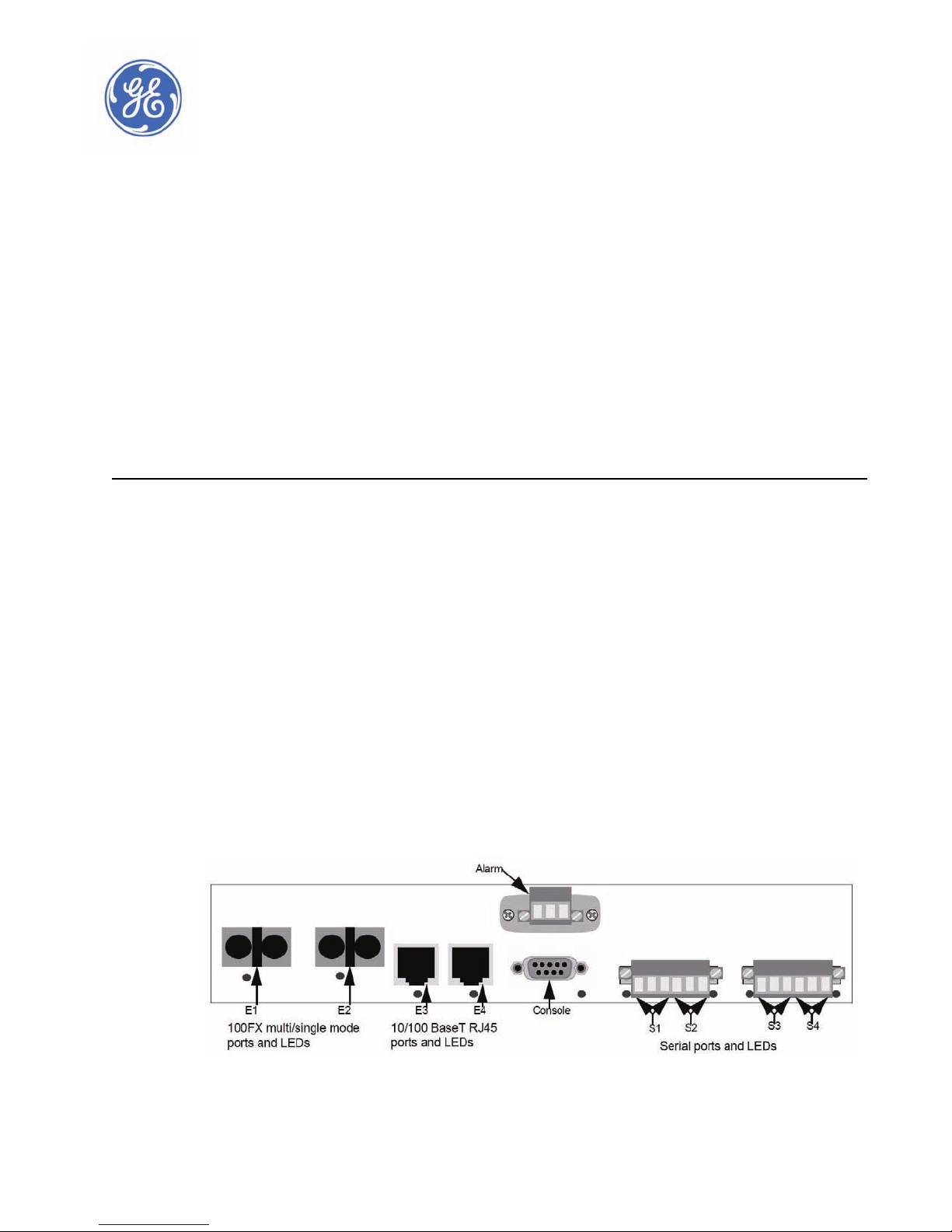
The following sections describe the features and requirements of the Multinet4.
The Multinet4 is equipped with:
•4 Ethernet Ports
• 2 100FX multi/single mode Fiber, LC, ST, and SC
• 2 10/100 BaseT, RJ45 Auto-negotiation and Auto-MDIX
OR
• 4 10/100 BaseT, RJ45 Auto-negotiation and Auto-MDIX
• 4 programmable RS232/485 serial ports
These ports are all located on the front face of the device, as illustrated in the figure below.
MULTINET4 MULTI-PORT SERIAL SERVER & MANAGED SWITCH – INSTRUCTION MANUAL 1–1
FIGURE 1–1: Front View
Page 10

OVERVIEW CHAPTER 1: OVERVIEW
1.1.2 Power and Ground
The Multinet4 can be ordered with a high (90 -250 VAC or VDC) or Low (24-48 VDC) voltage
power supply. The connection point for the power supply is located at the rear of the
chassis. The rear face also contains the primary ground stud and labels including serial
number, model number, and port and power specifications, as illustrated in the figure
below.
For detailed power specifications see Table 1–2:: Environmental Specifications.
FIGURE 1–2: Rear View
1.1.3 Indicators
The operational status of the ports of the Multinet4 is indicated by LEDs located near the
physical ports on the front of the Multinet4, as illustrated in FIGURE 1–1: Front View, and a
bank of LEDs on the top of the chassis, as illustrated in FIGURE 1–3: Top View.
1–2 MULTINET4 MULTI-PORT SERIAL SERVER & MANAGED SWITCH – INSTRUCTION MANUAL
FIGURE 1–3: Top View
Page 11

CHAPTER 1: OVERVIEW OVERVIEW
For 19” rail mounting hardware For DIN rail and panel mounting hardware
FRONT
1.1.4 Mounting Options
There are four mounting options for the Multinet4:
• 19” rack mount (see section 2.3.1.2 Mounting in a 19” Rail System - General2.3.1.2
Mounting in a 19” Rail System - General)
• 19” rack reverse mount (see section 2.3.1.4 Mounting in a 19” Rail System - Reverse
Mounting)
• Panel mount (see section 2.3.1.5 Mounting on a Panel)
• DIN rail mount (see section 2.3.1.6 Mounting in a DIN Rail System)
Each of these options requires specific accessory hardware. Each type of accessory
hardware mates up with a specific set of screw holes on the sides of the chassis, illustrated
in the figure below.
FIGURE 1–4: Side View
MULTINET4 MULTI-PORT SERIAL SERVER & MANAGED SWITCH – INSTRUCTION MANUAL 1–3
Page 12

OVERVIEW CHAPTER 1: OVERVIEW
1.2 Specifications
The following sections provide detailed information about the physical, electronic, and
industrial specifications of the Multinet4.
1.2.1 Physical
The physical dimensions and weight of the Multinet4 are defined in the table below.
Table 1–1: Physical Specifications
Height: 1.75 inches (4.45 cm)
Width: 9.5 inches (24.13 cm)
Depth: 9.5 inches (24.13 cm)
Weight: 5.0 lbs (2.3 kg)
1.2.2 Environmental
The environmental specifications of the Multinet4 are defined in the table below.
Table 1–2: Environmental Specifications
Operating Temperature:
UL / cUL /CE Safety Rating
Storage Temperature: -40°C to 85°C (-40°F to 185°F)
Operating Humidity: 95% non-condensing
50°C (122°F) maximum
1.2.3 Type Tests
.
Standard Name
Standard Number:Date
code
Electrostatic Discharge: Air and Direct EN/IEC61000-4-2:1995 Level 4 - 8Kv contact,15Kv air
Electrostatic Discharge: Air and Direct IEEE C37.90.3:2001 8Kv contact, 15Kv air
Severity levels Tested
Electrical Fast Transient / Burst Immunity EN/IEC61000-4-4:2004 Level 4 - 4KV @2.5Khz
Electrical Fast Transient / Burst Immunity IEEE C37.90.1:2002 Class 4 - 4KV for all port
Power Transients (high repetition) NEMA TS2 2.1.6.1:2003 300V,2500W
1–4 MULTINET4 MULTI-PORT SERIAL SERVER & MANAGED SWITCH – INSTRUCTION MANUAL
Page 13

CHAPTER 1: OVERVIEW OVERVIEW
Standard Name
Standard Number:Date
Severity levels Tested
code
Power Transients (low repetition high
energy)
NEMA TS2 :2003 600V, 1 Ohm impedance
Transients I/O terminals NEMA TS2 2.1.7.1 :2003 300V, 100 Ohms impedance
Serial: 4 kV on shield;
Surge Immunity IEC61000-4-5:2005
DC Power LO: 6kV L-E, 6kV L-L;
AC Power: 6kV L-E, 6kV L-L
Non Destructive transient Immunity NEMA TS2:2003 1000V, 1 Ohm impedance
Damped Oscillatory Burst EN/IEC61000-4-12 :2006
Damped Oscillatory IEEE C37.90.1:2002
Voltage Dip / Voltage Interruption EN/IEC 61000-4-11 :2004
Power Supply Ripple IEC 61000-4-17
Level 2 - 1kV common / 1kV
differential
2.5 kV common mode / 1kV
differential mode @1MHz
0% 5000msec, 40% 120msec,
70% 10msec
Level 3 - 10% & 15% of Rated
Voltage
RF Immunity 80-1000MHz EN/IEC 61000-4-3 :1998 Level 3 - 10V/m
RF Immunity 80-1000MHz IEEE C37.90.2:2004 35V/m
Conducted RF Immunity 150Khz -80 MHz IEC61000-4-6:1996 Level 3 - 10Vrms
Conducted RF Immunity 0-150Khz EN/IEC 61000-4-16:1998
Power Frequency Magnetic Field
Immunity
EN/IEC 61000-4-8:1993,2001
Level 3 - 15Hz-150Khz 1-10V
Level 4 - 15Hz-150KHz 1-30V
Level 5 - 100/200 A/m continuous 1000 A/m for 1s
Damped Magnetic Immunity IEC61000-4-10 Level 3 - 10A/m
Voltage Dips and Interrupts IEC61000-4-29
All test levels and durations Passes Criteria B
Conducted & Radiated Emissions CISPR22 / EN 55022 Class A
Conducted & Radiated Emissions FCC Part 15 Subpart B Class A
Rated Input Power IEEE C37.90 85% to110% of rated
AC voltage ranges IEC60870-2-1 + / - 10%
DC voltage ranges IEC60870-2-1 + / - 15%
ENVIRONMENTAL TESTS
Relative Humidity Cyclic EN/IEC 60068-2-30:2005 Variant 2 - 6 day @ 95%
Cold Temperature EN/IEC 60068-2-1: 1993/1990 -40 deg startup for 16 hours
MULTINET4 MULTI-PORT SERIAL SERVER & MANAGED SWITCH – INSTRUCTION MANUAL 1–5
Page 14

OVERVIEW CHAPTER 1: OVERVIEW
Standard Name
Standard Number:Date
Severity levels Tested
code
Dry Heat Temperature EN/IEC 60068-2-2: 1994,1974 +85 deg startup for 16 hours
Humidity NEMA TS2 2.1.5 -34 to 74C, 10-95%
MECHANICAL TESTS
Sinusoidal Vibration EN/IEC 60255-21-1: 1996,1988 Class 1 - 10-150hz @2G
Shock and Bump EN/IEC 60255-21-2: 1996,1988
Class 2 - 30G bump, 17G
shock
Shock NEMA TS2 2.2.9 10G, x,,y,z axis
Vibration MIL-STD -167-1 0.5G, 5-30 Hz
FUNCTIONAL TESTS
Operating Voltage NEMA TS2 2.1.2 Max nominal rating
Operational frequency NEMA TS2 2.1.3 Nominal +/- 3Hz
SAFETY TESTS
Dielectric IEEE C37.90
2kV on Hi model & 500V on Lo
model
Dielectric IEC60255-5 2kV
H.V Impulse IEEE C37.90 5kV
H.V Impulse IEC60255-5 5kV
OTHERS
IP rating IEC60529 IP20A
1.2.4 Power Requirements
The power requirements of the Multinet4 are defined in the table below.
Table 1–3: Power Requirements
High Voltage AC/DC Low Voltage DC
Voltage Input Range: 90-250 VAC/VDC 24-48 VDC
Max. Power (Watts): 27 27
1–6 MULTINET4 MULTI-PORT SERIAL SERVER & MANAGED SWITCH – INSTRUCTION MANUAL
Page 15

CHAPTER 1: OVERVIEW OVERVIEW
Table 1–3: Power Requirements
High Voltage AC/DC Low Voltage DC
Typical Power (Watts): 10 10
Max. Amperage (Amps): 0.3 1.3
1.2.5 Ports and External Connectors
The ports and external connectors of the Multinet4 are defined in the table below.
Table 1–4: Ports and External Connectors
Port Name Connector Description
Ethernet, E1 and E2 LC, SC, ST 100FX multi/single mode option card for fiber
optic Ethernet capable devices or Networks.
Ethernet, E3 and E4 RJ45 10/100 Mbps Ethernet port for connection to
copper Ethernet capable devices.
Serial, S1 through
S4
Phoenix 6-pin
header
Connection to serial async devices.
Configurable to 1200, 2400, 4800, 9600, and
19.2, 28.8, 33.6, 38.4, 57.6, 115.2 Kbps.
Power Connection Terminal block Non-polarized power input.
Facility Ground
Lug bolt Facility ground connection point.
Point
Console DB9, female Configured to operate at 38400 Baud, 8 bits,
No parity, one stop bit and is configured as a
DTE.
Alarm Phoenix 3-pin
Reserved for future use.
plug
Note
All copper I/O connections must be made with shielded cables and connectors.
1.2.6 Indicators
The status indicators of the Multinet4 are described in . There are two sets of LEDs so that
you can conveniently monitor activity regardless of the orientation of the device. One set is
on top to the Multinet4 (see FIGURE 1–3: Top View) and one set is on the front (see FIGURE
1–1: Front View).
MULTINET4 MULTI-PORT SERIAL SERVER & MANAGED SWITCH – INSTRUCTION MANUAL 1–7
Page 16

OVERVIEW CHAPTER 1: OVERVIEW
Table 1–5: Indicators
LED Name Condition Indication
S1 – S4
(Serial Ports)
Green Port is connected to an active serial device.
Off Port is down.
Flashing Data is passing through the port.
E1 – E4
(Ethernet Ports)
Green Port is connected to an active Ethernet device.
Off Port is down.
Flashing Data is passing through the port.
Console Green Connected to an active local terminal.
Off Not connected.
Flashing Data is passing through the port.
Alarm Off No power is applied to unit.
Red Reset state: System is not loaded
Orange System is being booted.
Green Normal operation.
1–8 MULTINET4 MULTI-PORT SERIAL SERVER & MANAGED SWITCH – INSTRUCTION MANUAL
Page 17
CHAPTER 1: OVERVIEW OVERVIEW
1.3 Pinouts
The following subsections describe the pinouts of the connectors used with the Multinet4.
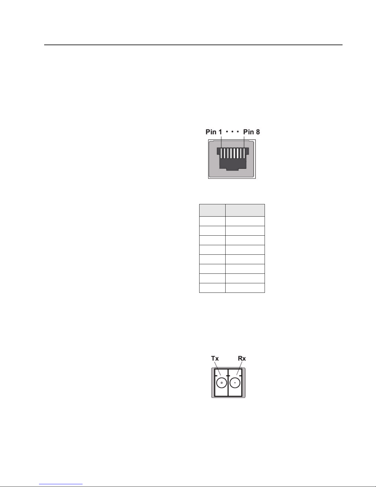
1.3.1 RJ45
Defines the pinout of the RJ45 connector used with the Multinet4. RJ45 connectors are
used on ports E3 and E4 for 10/100 BaseT connections to copper Ethernet-capable
devices.
Table 1–6: RJ45 Pinout
1.3.2 Fiber Optic
Pin Signal
1Tx +
2Tx -
3Rx +
4not used
5not used
6Rx -
7not used
8not used
The figure below defines the pinout of the Fiber connector used with the Multinet4. Fiber
connectors are used on ports E1 and E2 for 100FX multi/single mode for connections to
fiber optic Ethernet-capable devices or networks.
MULTINET4 MULTI-PORT SERIAL SERVER & MANAGED SWITCH – INSTRUCTION MANUAL 1–9
Page 18

OVERVIEW CHAPTER 1: OVERVIEW
Table 1–7: LC Pinout
Port Signal
Tx Transmit
Rx Receive
1.3.3 DB9 (Female) – Console Port
The figure below defines the pinout of the DB9 female connector for the console port for
asynchronous or bit-oriented connections.
Pin Name Dir. Description
1 DCD In Data Carrier Detect from DCE.
2 RXD In Receive Data from DCE.
3 TXD Out Transmit Data to DCE.
4 DTR Out Data Terminal Ready to DCE.
5 GND Pwr Signal Ground.
6 DSR In Data Set Ready from DCE.
7 RTS Out Request To Send.
8CTS In Clear To Send.
9 RI In Ring Indicator from DCE.
1.3.4 Phoenix Connector – Alarm Port
The figure below defines the pinout of the Phoenix 3-pin plug used with the alarm port on
the Multinet4.
Table 1–8: DB9 Pinout
1–10 MULTINET4 MULTI-PORT SERIAL SERVER & MANAGED SWITCH – INSTRUCTION MANUAL
Page 19

CHAPTER 1: OVERVIEW OVERVIEW
S1/S
Pin Signal
1 NC1 - normally closed 1
2 COM1 - common 1
3 NO1 - normally opened 1
1.3.5 Phoenix Connectors – Serial Ports
The figure below defines the pinout of the Phoenix 6-pin connector used with serial ports
on the Multinet4.
.
Table 1–9: Phoenix 6-pin Pinout
Pin RS232 RS485
S1
1GND COM
2RX1 RTX1-
3 TX1 RTX1+
S2
4GND COM
5RX2 RTX2-
6 TX2 RTX2+
Note
A 3/32” slotted screwdriver is required to connect/disconnect serial cables to/from the
Phoenix 6-pin connector.
Serial ports can be configured as RS232 or RS485 interfaces. Make sure to configure the
correct interface standard before connecting to the device. Improper setup can result in
damage to the unit.
MULTINET4 MULTI-PORT SERIAL SERVER & MANAGED SWITCH – INSTRUCTION MANUAL 1–11
Page 20

OVERVIEW CHAPTER 1: OVERVIEW
1.4 Features and Benefits
Multinet4 Multi-Port Serial Server & Managed Switch provides secure multiprotocol
networking in compact, rugged packages purpose-built for power utility substations and
other harsh environments. Cyber-security protection is assured by encrypted perconnection SSL, and port security features.
1.4.1 Multinet4 Multi-Port Serial Server & Managed Switch
The Multinet4 Serial Port Server & Managed Switch combines the capabilities of an
Ethernet Switch, an Async-to-TCP/IP Terminal Server in a single integrated device.
Dual fiber Ethernet connectivity coupled with Rapid Spanning Tree ensure resilient
backbone communications.
The Multinet4 provides full perimeter protection when used as a terminal server at remote
critical facilities. Per-session encrypted SSL capabilities permit fine-grained security
extended to end-point connections when used as a distributed terminal server in larger
installations.
The Multinet4 is a multi-function, multi-protocol networking platform, purpose-built for
distributed industrial automation applications such as Supervisory Control and Data
Acquisition (SCADA) systems.They support a wide range of communications interfaces
used by industrial devices, enabling multiple generations of remote devices and support
systems to be consolidated onto a single integrated network infrastructure. The Multinet4
also operates effectively in extremely harsh environmental conditions such as those within
power utility substations, pumping stations, treatment plants, transportation systems,
pipelines and wind farms. This robustness is primarily due to extended-range
specifications in areas such as electromagnetic interference, temperature and electrical
surges. Most other networking products will fail when facing these conditions.
The Multinet4 has been rigorously tested to extreme industrial specifications for
temperature, electrical surge protection and immunity. It is packaged in a steel or steel
and aluminum case with no fans or moving parts and has been subjected to
manufacturing test and control processes that include temperature cycling and prolonged
product burn-in to ensure reliability delivered to the field. Physical product reliability is
complemented by advanced network resiliency features that enable redundant and dualrouted network designs that protect network availability despite facility/element failures.
1–12 MULTINET4 MULTI-PORT SERIAL SERVER & MANAGED SWITCH – INSTRUCTION MANUAL
Page 21

CHAPTER 1: OVERVIEW OVERVIEW
1.4.2 Features Summary
The table below summarizes the hardware features of the Multinet4.
Table 1–10: Hardware Features Summary
Feature Details
Connectivity •4 Ethernet ports
— 2 100FX multi/single mode Fiber, ST, SC, and
LC
— 2 10/100 BaseT, RJ45 Auto-Negotiation and
Auto-MDIX
OR
— 4 10/100 BaseT, RJ45 Auto-Negotiation and
Auto-MDIX
• 4 programmable RS232/485 serial ports
Power Options • High (90 -250 VAC or VDC)
• Low (24-48 VDC)
Mounting Options •Panel
• DIN-rail
• 19” rack
• 19" rack reverse
The table below summarizes the features of the Multinet4.
Table 1–11: Software Features Summary
Feature Details
Serial Port Management • Up to 16 serial profiles
• Serial data statistics
• RS-232 (Full/Half) & RS-485 (Full/Half) supported via software
selection
• Data rates from 1200 baud to 115200 bps
• 7 or 8 data bits
• 1, 1.5, or 2 stop bits
• Even, Odd, or No Parity
• Hardware and Software (XON/XOFF) Flow Control
• Packetization options
— Forward on specific character, idle time, or
packet size
— Turnaround timer
MULTINET4 MULTI-PORT SERIAL SERVER & MANAGED SWITCH – INSTRUCTION MANUAL 1–13
Page 22

OVERVIEW CHAPTER 1: OVERVIEW
Table 1–11: Software Features Summary
Feature Details
Terminal Server • Active, passive, and mixed connection modes
• Telnet and raw TCP sessions
• Multiple incoming connections per serial port
Ethernet Port Management • Supported media types include 10/100BaseTX and 100FX
• 10, 100, or Auto speed selections for 10/100BaseTX
Auto-Negotiation and Auto-MDIX
• Half or full duplex operation for 10/100BaseTX
• Ethernet frame statistics
• Port Rate Limiting based on packet type (broadcast,
multicast, flood, all)
• Port Mirroring
Ethernet Switching • Maximum Station Cache capacity of 1,024 random MAC
addresses
• Up to 64 static MAC addresses
• Purge Dynamic Cache Entries
• 802.1D-compliant Learning Bridge
Rapid Spanning Tree Protocol
(RSTP))
•STP
•RSTP
VLANs • Up to 16 different VLANs
• Tagged and untagged operation
• VLAN security (tag-based filtering)
• Optional egress tag stripping
QoS • Flexible flow-based DiffServ marking for all routed packets
• Configurable mapping of DiffServ marking to 802.1p priority
tag for all routed packets
• 4-Level priority queuing for Ethernet switching based on IEEE
802.1p tag, IP DiffServ marking, or ingress port.
Security • Secure Web Server using HTTP over SSL (https://)
• User authentication via RADIUS
• Authenticated and encrypted terminal server connections
over SSL
• RSA public key and X.509 certificate management and
generation
• Web-based upload of new keys and certificates
• Supports a number of SSL and TLS cipher suites that include
support for RSA public keys, 3DES/AES/RC4 encryption, and
MD5/SHA1 hashing
1–14 MULTINET4 MULTI-PORT SERIAL SERVER & MANAGED SWITCH – INSTRUCTION MANUAL
Page 23

CHAPTER 1: OVERVIEW OVERVIEW
Table 1–11: Software Features Summary
Feature Details
Embedded Web Server
(HTTP/HTTPS)
•Primary User Interface
• Compatible with standard web browsers (such as Internet
Explorer or Firefox)
User Account Management • Configurable security policies
• Up to 16 user accounts
• Stored passwords are hashed using MD5
Configuration File Management • XML Configuration Files
• Web-based Upload/Download
• Multiple configurations stored in Flash File System
Software Image Management • Software upgrade with revert capability
• Web-based upload of new software images
Time and Date Management • Real-time clock support
• Active or passive-mode SNTP client
• Time offsets, time zone and Daylight Saving T ime support
• Up to 3 SNTP servers can be specified for redundancy
Event Logging • Flexible logging options
• Log files stored in flash file system
• SYSLOG capability
• Up to 5 remote collectors may be specified
SNMP v1/v2c/v3 Agent • Supports User-based Security Model (USM) when v3 is
enabled
• MIB-II and SNMPv2 Traps
• Up to 4 remote management/trap destinations may be
specified
• Proprietary Enterprise MIB
Modbus/TCP • Modbus/TCP to Modbus/RTU or Modbus/ASCII encapsulation
• Support for multiple masters and slaves
• Maps Modbus device addresses to configurable remote IP
addresses
• Enables multi-master access to slaves on a single bus by
serializing Modbus requests at the server, a capability not
possible in normal serial Modbus
Protocol Monitor • Sniffs ingress and egress packets on any port
• Filter by MAC address, IP address, TCP port, or protocol
• Displays frame addresses, ports, protocol identifier, and data
payload
MULTINET4 MULTI-PORT SERIAL SERVER & MANAGED SWITCH – INSTRUCTION MANUAL 1–15
Page 24

OVERVIEW CHAPTER 1: OVERVIEW
1–16 MULTINET4 MULTI-PORT SERIAL SERVER & MANAGED SWITCH – INSTRUCTION MANUAL
Page 25

Digital Energy
Multilin
Multinet4 Multi-Port Serial Server
& Managed Switch
Chapter 2: Getting Started
Getting Started
The Multinet4 Multi-Port Serial Server & Managed Switch provides connectivity to
asynchronous and Ethernet traffic through four programmable serial ports, two 10/100
BaseT Ethernet ports for copper line connections, and two 100FX multimode (MM) or
singlemode (SM) for fiber optic connections.
2.1 Installation
2.1.1 Tools
2.1.2 Site Suitability
The Multinet4 is designed to be installed in standard 19" racks, on a DIN rail system, or on a
panel.
Regardless of the mounting system you are using, you will need the following tools:
• Two screw drivers – one phillips head and one slot.
• A torque wrench (rated for ten and 32 inch pounds, or
• A wrench to connect a ground wire from the device chassis to a ground
The instructions in this chapter cover only the physical installation. System configuration is
handled through a web-based interface and is described in Chapter 4.
Be sure that your installation site meets the following criteria:
• Conforms with the temperature and humidity ranges, detailed in Table 1–2::
Environmental Specifications.
• Can meet the power requirements, detailed in Table 1–3:: Power Requirements.
• Will remain stable after the addition of the 5 lb. Multinet4.
• Permits at least two inches (5.1cm) of space between the Multinet4 and any other
heat-producing device.
1.1 Nm and 3.6 Nm)
MULTINET4 MULTI-PORT SERIAL SERVER & MANAGED SWITCH – INSTRUCTION MANUAL 2–1
Page 26

GETTING STARTED CHAPTER 2: GETTING STARTED
2.1.3 Wiring and Grounding Guidelines
The Multinet4 requires several different types of connectors, cables, and wires.
Requirements and recommendations are listed below:
Fiber The fiber cables connected to the Multinet4 must be:
• non-dispersion shifted, single mode (SM)
or
• multi-mode (MM) fiber cables defined by the Telcordia Technologies
General Recommendation 20-CORE standard
and
• terminated with LC, ST, and SC connectors
Grounding The primary ground stud located on the rear of the chassis must be used to
connect to an approved ground with a wire meeting the following criteria:
• 14 AWG (minimum)
• a maximum of five feet in length
• terminated on the ground lug side with a #10 ring lug
Facility Power The facility power cabling attached to the Multinet4 chassis must meet the
Copper Copper I/O cables and connectors must be shielded.
It is mandatory that an accessible disconnect is provided in the Installation wiring
2.1.4 Fiber Optic Safety
Before installing the Multinet4 you should be aware that devices that employ laser
technology, such as the fiber optical LC ports and associated cabling, can be dangerous.
Do not look directly into a fiber optic port or into the end of a fiber optic line. Doing so
could cause injury to your eye or blindness. Always assume that there is laser activity in the
line or port, even if the device is powered down. As a reminder, whenever this manual calls
for the handling of fiber optic lines, those instructions will be accompanied by a “Laser
Warning,” as follows:
following criteria:
• cabling constructed using 14 AWG stranded wire
• cable firmly attached to the terminal holes of the non-polarized
power unit, as illustrated in FIGURE 2–11:: Non-Polarized Power Input.
• cable routed and strain relieved to the chassis according to good
wiring practices
DO NOT LOOK INTO A FIBER OPTIC CABLE OR PORT! These can produce invisible light that
may do serious eye damage. Always assume that fiber optic cables or ports are actively
radiating light energy.
2–2 MULTINET4 MULTI-PORT SERIAL SERVER & MANAGED SWITCH – INSTRUCTION MANUAL
Page 27

CHAPTER 2: GETTING STARTED GETTING STARTED
2.1.5 Fiber Optic Handling
Contamination from dust, dirt, oils from the hands and other sources can impede the
transmission and reception of optical signals through the optical fibers.When handling the
optical connectors and fiber cables, follow these precautions to minimize the
contamination of the connectors and ports:
• Cover optical connectors and ports with dust caps when they are not in use.
• Do not touch fiber tips or the interior of optical ports when handling fiber cables
and connectors.
• Clean fiber optic connectors as described in 2.4.2.1: Cleaning Connectors, prior to
making any optical connection.
• Clean optical ports as described in 2.4.2.2: Cleaning Optical Ports if contaminants
or degraded performance are noted on the interface.
Fiber optic connectors should be cleaned after each use and optical ports should be
cleaned if you notice contamination or degraded performance.
Fiber optic cables and connectors are fragile and can be easily broken through rough
handling. When handling fiber optic media, take the following precautions:
• Do not strike the fiber cable with tools.
• Do not pinch, crimp, or compress the jacketing of the optical cable.
• Do not use less than the minimum bend radius of 3 inches (7.62 cm) when routing
or coiling cables.
2.1.6 External Connections
You can speed up the installation of the Multinet4 by having the following equipment and
information on hand before beginning:
• A supply of cables and connectors of the required types.
• IP addresses for new devices and any existing devices you will be connecting to.
• Your notes on naming conventions and end point information.
MULTINET4 MULTI-PORT SERIAL SERVER & MANAGED SWITCH – INSTRUCTION MANUAL 2–3
Page 28

GETTING STARTED CHAPTER 2: GETTING STARTED
2.2 Unpacking
Unpack and inspect the Multinet4.
The Multinet4 is shipped with the following items in the box:
• Multinet4 unit
• Appropriate mounting brackets (19’ rail, or DIN rail, or panel), with screws
• Document CD-ROM
• Console Cable - DB9 terminations, 10' long
• Ethernet cable - RJ45 terminations, 10' long
Be sure that all the equipment you have ordered is included in the shipment.
Remove the unit from the styrofoam end caps and inspect the Multinet4 chassis for dents
or other shipping related damage. Report any damage immediately to GE Multilin
Customer Support and DO NOT INSTALL the unit.
2–4 MULTINET4 MULTI-PORT SERIAL SERVER & MANAGED SWITCH – INSTRUCTION MANUAL
Page 29

CHAPTER 2: GETTING STARTED GETTING STARTED
2.3 Installation of the Multinet4 Unit
To install the Multinet4 you must first
• Mount it
• Make the ground and power connections.
• Connect the network cables
2.3.1 Mounting
Before mounting, please note the following:
1. Elevated Operating Ambient - If installed in a closed or multi-unit rack assembly, the
operating ambient temperature of the rack environment may be greater than room
ambient. Therefore, consideration should be given to installing the equipment in an
environment compatible with the maximum ambient temperature (Tma) specified by
the manufacturer.
2. Reduced Air Flow - Installation of the equipment in a rack should be such that the
amount of air flow required for safe operation of the equipment is not compromised.
3. Mechanical Loading - Mounting of the equipment in the rack should be such that a
hazardous condition is not achieved due to uneven mechanical loading.
4. Circuit Overloading - Consideration should be given to the connection of the
equipment to the supply circuit and the effect that overloading of the circuits might
have on overcurrent protection and supply wiring. Appropriate consideration of
equipment nameplate ratings should be used when addressing this concern.
5. Reliable Earthing - Reliable earthing of rack-mounted equipment should be
maintained. Particular attention should be given to supply connections other than
direct connections to the branch circuit (e.g. use of power strips)."
2.3.1.1 Mounting Hardware
Your Multinet4 shipment includes the mounting hardware you have ordered as
appropriate to your site.This hardware is one of:
• A pair of 4.5” brackets for conventional mounting in a 19” rail system (that is, with I/
O connections on the “aisle side” of the rack)
• A pair of 8.75” brackets for reverse mounting in a 19” rail system (that is, with I/O
connections on the “wire side” of the rack)
• A pair of 1.5” brackets for mounting on a panel.
• A DIN rail mounting bracket.
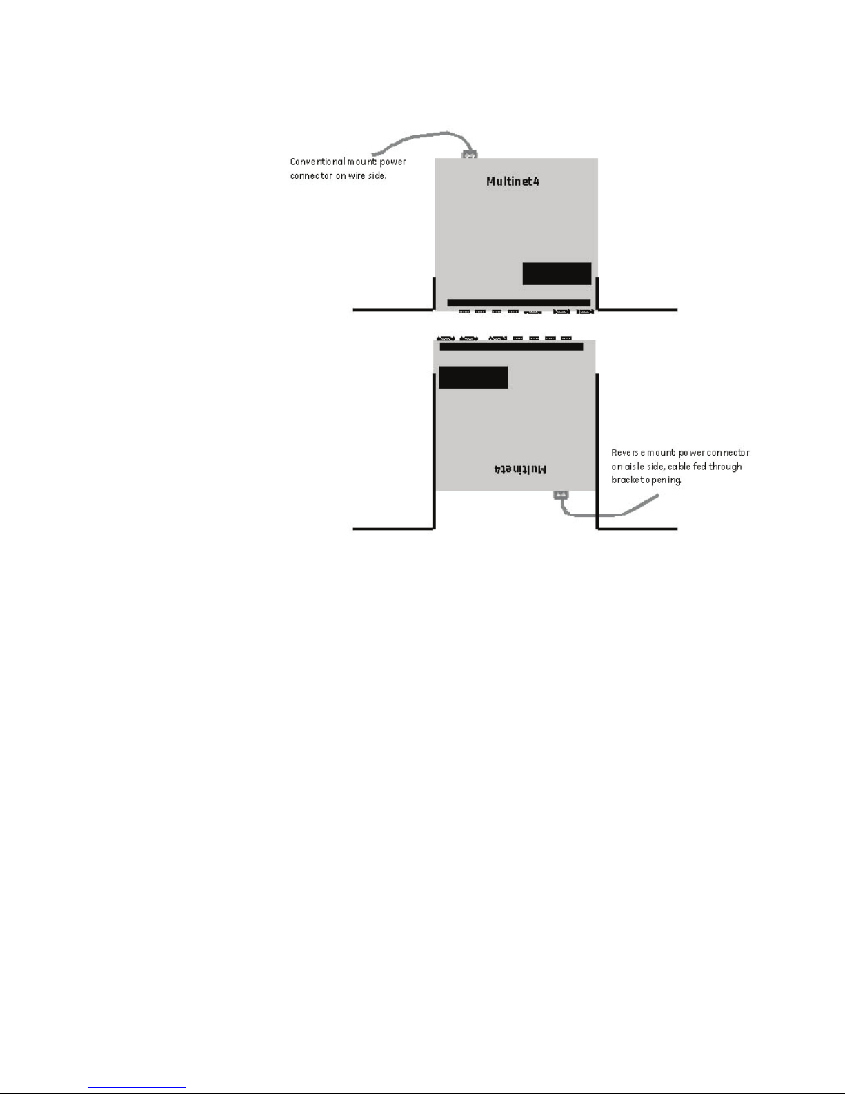
2.3.1.2 Mounting in a 19” Rail System - General
The Multinet4 device can be mounted in a 19” rail system with the I/O connectors on the
aisle side and the power and ground connectors on the wire side (conventional mounting)
or in the reverse configuration.
MULTINET4 MULTI-PORT SERIAL SERVER & MANAGED SWITCH – INSTRUCTION MANUAL 2–5
Page 30
GETTING STARTED CHAPTER 2: GETTING STARTED
FIGURE 2–1: Top View: 19” Rail Conventional and Reverse Mounting
2.3.1.3 Mounting in a 19” Rail System - Conventional Mounting
The brackets for mounting in a 19-inch rail system attach with two screws to the screw
holes located toward the front of the Multinet4. You can adjust the depth of the device
within the mounting system to four positions:
• By your selection of which pair of screw holes on the short side of the bracket (that
is, the side that attaches to the Multinet4) to use.
• By setting the long side of the bracket (that is, the side that attaches to the rail
system) toward the front of the Multinet4 or toward the rear.
2–6 MULTINET4 MULTI-PORT SERIAL SERVER & MANAGED SWITCH – INSTRUCTION MANUAL
Page 31

CHAPTER 2: GETTING STARTED GETTING STARTED
CONSOLE
ALARM
S1
S2
S3
S4
E1
E2
E3
E4
18.9in (48cm)
9.4in (23.9cm)
4.75in (12.07cm)
4.75in (12.07cm)
1.7in
(4.32cm)
1.25in
(3.18cm)
18.2in (46.2cm)
FIGURE 2–2: 19” Rail Conventional Mounting brackets
FIGURE 2–3: 19” Rail Conventional Mounting - Dimensional Drawing
2.3.1.4 Mounting in a 19” Rail System - Reverse Mounting
The brackets provided for reverse mounting have an opening in their forward projecting
parts to accommodate the power cable.
MULTINET4 MULTI-PORT SERIAL SERVER & MANAGED SWITCH – INSTRUCTION MANUAL 2–7
Page 32

GETTING STARTED CHAPTER 2: GETTING STARTED
18.9in (48cm)
9.4in (23.9cm)
4.75in (12.07cm)
4.75in (12.07cm)
1.7in
(4.32cm)
1.25in
(3.18cm)
18.2in (46.2cm)
24-48V
1.3A
NON-POLARIZED
Serial No:
0650 0034
DX800-01-L-P
FIGURE 2–4: 19” Rail Reverse Mounting brackets
FIGURE 2–5: 19” Rail Reverse Mounting - Dimensional Drawing
2.3.1.5 Mounting on a Panel
The brackets for mounting on a panel attach with two screws to the screw holes located
toward the rear of the Multinet4. You can adjust the distance of the Multinet4 from the
panel to two positions by your selection of which pair of screw holes to use in attaching the
bracket to the Multinet4.
2–8 MULTINET4 MULTI-PORT SERIAL SERVER & MANAGED SWITCH – INSTRUCTION MANUAL
Page 33

CHAPTER 2: GETTING STARTED GETTING STARTED
12.7in (32.26cm)
11.1in (28.2cm)
9.4in (23.88cm)
8.8in (22.35cm)
5.48in (13.9cm)
0.5in (1.27cm)
0.5in (1.27cm)
1.65in (4.2cm)
0.85in (2.16cm)
FIGURE 2–6: Panel Mounting brackets
MULTINET4 MULTI-PORT SERIAL SERVER & MANAGED SWITCH – INSTRUCTION MANUAL 2–9
FIGURE 2–7: Panel Mounting - Dimensional Drawing
Page 34

GETTING STARTED CHAPTER 2: GETTING STARTED
2.3.1.6 Mounting in a DIN Rail System
The DIN rail bracket rides on the bottom of the Multinet4 and is attached with four screws
into the two pair of screw holes located toward the back of the Multinet4. The bracket
attaches to the DIN rail by means of a pair of stationary prongs near the top of the bracket
and a single spring-loaded prong (the release mechanism) toward the bottom of the
bracket.
To fasten the Multinet4 into a DIN rail system begin by slipping the upper pair of prongs
over the top of the rail. Then, while depressing the spring-loaded release mechanism (as
illustrated in the figure below), press the Multinet4 flush against the DIN rail and remove
the screwdriver to allow the release mechanism to close. Check to make sure that the top
and bottom prongs on the bracket are securely attached to the DIN rail.
When the Multinet4 is fastened into the DIN rail system it can be released by downward
pressure on the release mechanism. The DIN rail bracket supplied with the Multinet4 is
equipped with a metal “tail” that projects below the chassis of the mounted Multinet4. To
unmount the Multinet4 insert the tip of a screwdriver into the slot a the bottom of this tail
and pull up on the handle of the screwdriver to force the release mechanism down.
2–10 MULTINET4 MULTI-PORT SERIAL SERVER & MANAGED SWITCH – INSTRUCTION MANUAL
FIGURE 2–8: Multinet4 with DIN Rail bracket attached
Page 35

CHAPTER 2: GETTING STARTED GETTING STARTED
9.4in (23.88cm)
6.3in (16cm)
9.14in (23.22cm)
5.94in (15.09cm)
2.89in
2.85in
<->
<->
2.43in
(6.17cm)
1.7in
(4.32cm)
.35in
.38in
(.95cm)
<>
FIGURE 2–9: DIN Rail Mounting - Dimensional Drawing
2.3.2 Connecting Facility Power
The Multinet4 comes in either high or low voltage models. The unit does not have a power
on/off switch and is active when the power is connected.
ELECTRICAL WARNING: Always ensure that the ground connection is made prior to
connecting facility power to the Multinet4. The ground provides a protective circuit
connection to ground in cases of transients and power surges. Connect the facility power
to a DC or AC unit as described in the following sections.
2.3.2.1 Making the Ground and Power Connections
The Multinet4 provides a hardened DC or AC power supply for industrial applications and/
or hostile environments. The ground lug and power supply connector are located on the
rear of the unit as shown in the figure below.
MULTINET4 MULTI-PORT SERIAL SERVER & MANAGED SWITCH – INSTRUCTION MANUAL 2–11
Page 36

GETTING STARTED CHAPTER 2: GETTING STARTED
FIGURE 2–10: Ground and Power Connections
ELECTRICAL WARNING: Verify that a proper ground connection is made from the ground
lug to facility ground prior to connecting power to the Multinet4. Failure to have a proper
ground path could cause serious injury or death to personnel in cases of power surges.
Making the Ground Connection
The ground wire should be 14 AWG terminated with a #10 ring lug.
Make the facility ground connection as follows:
Z Loosen the ground bolt on the chassis, insert the #10 ring lug, and
tighten the ground bolt.
Z Connect the other end of the ground wire to the facility ground.
Making the Power Connection
The power wires should be 14 AWG terminated with a #6 ring lug. Smaller wires may be
used, down to 18 AWG, but verify that they meet your local electrical requirements.
Connect the power to the unit as follows.
ELECTRICAL WARNING: Ensure that power is disconnected from wiring prior to handling!
Check the voltage rating next to the power connector - verify that it matches the power
source.
Z Remove the plug portion of the power connector by loosening the
two captive mounting screws.
Z Strip back 1/4" off the insulation of the wires that will connect the
unit to the power source.
Z Loosen saddle screws and insert each conductor firmly into a
terminal hole of the plug (note: this connection is not polarity
sensitive.)
2–12 MULTINET4 MULTI-PORT SERIAL SERVER & MANAGED SWITCH – INSTRUCTION MANUAL
Z Visually inspect that no strands of wire are straying out of the hole,
potentially shorting to ground or the other conductor. Tighten the
saddle screws until the wires are secure.
Page 37

CHAPTER 2: GETTING STARTED GETTING STARTED
saddle screws
captive mounting screws
terminal holes
Z Re-insert the plug into the power connector and secure the two
captive mounting screws.
FIGURE 2–11: Non-Polarized Power Input
2.3.3 Connecting to the Console Port and the Alarm Port
2.3.3.1 Console Port
Use a DB9 null-modem cable or a DB9-to-USB null-modem cable, to connect the Multinet4
console port (the RS232 port) to the PC.
2.3.3.2 Alarm Port
Resevered for future use.
2.3.4 Connecting Network Cables
There are three types of connections that can be made to the Multinet4. They are serial,
Ethernet copper, and Ethernet fiber optic. The following sections describe each type of
connection separately.
2.3.4.1 Connecting Serial Cables
This procedure assumes that one end of the Serial device cable is already attached to the
end unit. Be aware of the serial port numbering scheme when installing the cables see (see
section1.3: Pinouts). The ports are configured in software later on and if a device is
accidentally connected to the wrong port it will be difficult to detect.
Connect cables to the serial ports as described below (A 3/32” slotted screwdriver is
required.):
1. Remove the plug portion of the phoenix connector by loosening the two captive
mounting screws.
2. Strip back 1/4" off the insulation of the wires.
3. Loosen saddle screws and insert each conductor firmly into a terminal hole of the
4. Visually inspect that no strands of wire are straying out of the hole, potentially
MULTINET4 MULTI-PORT SERIAL SERVER & MANAGED SWITCH – INSTRUCTION MANUAL 2–13
plug
shorting to ground or the other conductor.
Page 38

GETTING STARTED CHAPTER 2: GETTING STARTED
5. Tighten the saddle screws until the wires are secure.
6. Re-insert the plug into the phoenix connector and secure the two captive mounting
screws.
Note
Serial cables must be shielded. It is recommended that high quality Belden 9843 cables be
used whenever possible to provide reliable serial communication.
2.3.4.2 Connecting RJ45 Twisted Pair
The RJ45 ports of the Multinet4 can be connected to the following two media types:
100Base-TX and 10Base-T. CAT Five cables should be used when making 100Base-TX
connections. When the ports are used as 10Base-T ports, CAT.3 may be used. In either
case, the maximum distance for unshielded twisted pair cabling is 100 m (328 ft.).
Note
It is recommended that high quality CAT. 5 cables (which work with 10 Mb and 100 Mb) be
used whenever possible to provide flexibility in a mixed-speed network, as dual-speed
ports are auto-sensing for 10 and 100 Mb/s.
The following procedure describes how to connect a 10Base-T or 100Base-TX twisted pair
segment to the RJ45 port. The procedure is the same for both unshielded and shielded
twisted pair cables.
Z Using standard twisted pair media, insert either end of the cable
with an RJ45 plug into the RJ45 connector of the port.
Even though the connector is shielded, either unshielded or
shielded cables may be used.
Z Connect the other end of the cable to the corresponding device.
Z Use the LINK LED to ensure connectivity by noting that the LED will
be illuminated when the unit is powered and connection is
established.
2.3.4.3 Connecting ST-type Fiber Optics (twist-lock)
The following procedure applies to installations using modules with ST-type fiber
connectors.
Z Before connecting the fiber optic cable, remove the protective dust
caps from the tips of the connectors on the module.
Save these dust caps for future use.
Z Wipe clean the ends of the dual connectors with a soft cloth or
lintfree lens tissue dampened in alcohol.
Ensure the connectors are clean before proceeding.
Note
One strand of the duplex fiber optic cable is coded using color bands at regular intervals.
The color-coded strand must be used on the associated ports at each end of the fiber optic
segment.
Z Connect the transmit (TX) port on the module (light colored post) to
the receive (RX) port of the remote device.
Begin with the color-coded strand of the cable for this first TX-toRX connection.
2–14 MULTINET4 MULTI-PORT SERIAL SERVER & MANAGED SWITCH – INSTRUCTION MANUAL
Page 39

CHAPTER 2: GETTING STARTED GETTING STARTED
Z Connect the receive (RX) port on the module (dark colored post) to
the transmit (TX) port of the remote device.
Use the non-color coded fiber strand.
The LINK LED on the module will illuminate when a connection has been established at
both ends (assuming power is ON). If LINK is not lit after cable connection, the cause may
be improper cable polarity. Swap the fiber cables at the module connector to remedy this
situation.
2.3.4.4 Connecting SC-type or LC-type Fiber Optics (snap-in)
The following procedure applies to installations using modules with SC-type or LC-type
connectors.
When connecting fiber media to SC/LC connectors, simply snap the two square male
connectors into the module’s SC/LC female jacks until the click and secure.
2.3.4.5 Connecting Single-mode Fiber Optics
When using single-mode fiber cable, be sure to use single-mode fiber port connectors.
Single-mode figer cable has a smaller diameter than multi-mode fiber cable (9/125
microns for single-mode versus 50/150 or 62.5/125 microns for multi-mode, where xx/yy
represent the core diameters and the core plus cladding respectively). Single-mode fiber
allows full bandwidth at longer distances and may be used to connect 10 Mb nodes up to
10 Km.
The same connection procedures for multi-mode fiber apply to single-mode fiber
connectors. Follow the steps listed in 2.3.4.3: Connecting ST-type Fiber Optics (twist-lock)
and 2.3.4.4: Connecting SC-type or LC-type Fiber Optics (snap-in) shown above.
MULTINET4 MULTI-PORT SERIAL SERVER & MANAGED SWITCH – INSTRUCTION MANUAL 2–15
Page 40

GETTING STARTED CHAPTER 2: GETTING STARTED
2.4 Maintenance
The Multinet4 is designed to be replaced as a unit. There are no servicing requirements and
there are no user-repairable components in this device. Maintenance is limited to replacing
the unit and cleaning any fiber optic connectors and ports.
The following sections detail disconnecting all connections to the chassis, removing the
chassis, cleaning optical devices and packing the Multinet4 for return to the manufacturer.
If it is still possible to connect a terminal to the malfunctioning Multinet4 and retrieve any
configuration data from the device, do so prior to removing power.
2.4.1 Removing the Multinet4
Removing the Multinet4 entails disconnecting the power lines, disconnecting the network
cabling, and removing the chassis from the rack or other installation location. The unit can
then be packed for shipment to the manufacturer.
2.4.1.1 Disconnecting Power and Ground Lines
ELECTRICAL WARNING: Before disconnecting either AC or DC power connections
at the Multinet4 ensure that the facility power has first been turned off. Failure to shut
power off prior to removing the power connections could expose you to dangerous
voltages causing injury or death.
Follow the procedure below to disconnect the power and ground lines.
Z Verify that power to the Multinet4 is turned off.
Z Use a screw driver to loosen the two screws that tighten the wire
clamps in the non-polarized power connector.
Z Remove the wires from the connector.
ELECTRICAL WARNING: If the wires are not to be used immediately properly insulate them
to ensure that an accidental turning on of the power will not cause a short or electrical
hazard.
Z Remove the ground wire from the chassis by loosening the Ground
Lug.
2.4.1.2 Disconnecting Network Cables
The sequence for removal of the serial and Ethernet cables is not important, but it is
important to note that there are active devices connected to each end of the cable.
Z Remove all wires from the Phoenix serial ports by unscrewing the
saddle screws and pulling one wire off one port. (Label the wire
with the port number if the cable is to be reconnected at some
later time.)
Z Remove the Ethernet RJ45 connectors from the Ethernet ports by
pressing on the clip on the underside of the modular connector and
pulling the connector straight out. (Label the connector with the
port number if the cable is to be reconnected at some later time.)
2–16 MULTINET4 MULTI-PORT SERIAL SERVER & MANAGED SWITCH – INSTRUCTION MANUAL
Page 41

CHAPTER 2: GETTING STARTED GETTING STARTED
LASER WARNING: DO NOT LOOK INTO A FIBER OPTIC CABLE OR PORT! These can produce
invisible light that may do serious eye damage. Always assume that fiber optic cables or
ports are actively radiating light energy.
Z Following the safe handling procedures for fiber optic cables and
connectors, remove any fiber optic cable connected to the
Ethernet fiber ports. Immediately install dust caps on the cable end
and the fiber port. (Label the connector with the port number if the
cable is to be reconnected at some later time.)
2.4.1.3 Packing the Multinet4 for Shipment
If you have saved the shipping box that your Multinet4 was received in then add the end
styrofoam pieces around the chassis and place the unit in the box. Please contact
customer support to receive a valid RMA number so that this item is either repaired and
returned or credited to your account. Products without a proper RMA number will not be
accepted for repair by GE Multilin.
If you have not saved the original shipping container then place the unit in a box so that
normal shipping activities will not cause any damage to the unit. GE Multilin has no
responsibility for the product during return shipping.
2.4.2 Cleaning Fiber Optic Devices
This section covers the cleaning requirements and procedures for the fiber optic cable
connectors and the optical ports on the Multinet4. Clean the connectors after each use
and the optical ports when contamination is suspected or there is a performance
degradation which may be attributable to contamination. All fiber optic connectors and
optical ports should be capped with dust caps when not in use.
The cleaning materials used should be rated for fiber optic devices. Specifically cloth,
wipes and swabs should be lint-free, non-abrasive and free of additives. Cleaning fluids
should be restricted to optical-grade isopropyl alcohol. Canned (compressed) air should be
used to blow out dust and particulate matter and to dry residual isopropyl alcohol after
cleaning.
2.4.2.1 Cleaning Connectors
These instructions are recommended each time a fiber optic connector is used. Clean the
fiber optic connectors as follows:
Z Blow out any dust or particulate matter from the connector end,
Z Wipe out the connector end surfaces with a cloth or pad saturated
Z Blow dry the connector surfaces, using canned air, by directing the
using canned air.
in isopropyl alcohol.
air flow across the tip but not directly down onto the tip.
MULTINET4 MULTI-PORT SERIAL SERVER & MANAGED SWITCH – INSTRUCTION MANUAL 2–17
Z Using care not to touch the fiber tip, install a dust cap or connect to
an optical port.
Page 42

GETTING STARTED CHAPTER 2: GETTING STARTED
2.4.2.2 Cleaning Optical Ports
These instructions are recommended only when there is evidence of contamination or
when reduced performance has been detected. Clean the optical ports as follows:
Z If required, remove the fiber optic connector from the optical port
and clean the connector as described in “Cleaning Connectors,”
above.
Z Insert the extension tube, supplied with the canned air, into the
canned air nozzle and blow out the optical port. Use care not to
touch the bottom of the optical port.
Z Reconnect the fiber optic connector removed in step 1.
If degraded performance persists, perform the following additional steps:
Z Remove the fiber optic connector and place a dust cap on the end.
Z Using a small-head, lint-free swab gently wipe out the optical port.
Repeat steps 2 and 3 above.
2–18 MULTINET4 MULTI-PORT SERIAL SERVER & MANAGED SWITCH – INSTRUCTION MANUAL
Page 43

CHAPTER 2: GETTING STARTED GETTING STARTED
2.5 Software Management
The EnerVista Multinet4 Setup software or the Web Administrator interface or CLI interface
can be used to manage and configure the Multinet4. The EnerVista Multinet4 Setup
software is the preferred method to edit the most common used setting. The setup
software connects to the unit through the Ethernet port.
Multinet4 is implemented by an easily upgradeable software image and by configuration
files.
Software images can be upgraded with the EnerVista Multinet4 Setup > Maintenance >
Upload Firmware, which loads an executable software image into non-volatile memory.
Configuration files can be maintained and upgraded with EnerVista Multinet4 Setup >
Advanced Setting > Administration > Configuration screen.
The Multinet4 comes with a factory-supplied software image and configuration file. After
you have completed the hardware installation you need only replace the default IP address
with another that places your PC and the Multinet4 on the same subnet. You can then
access the Multinet4’s supervisory software and begin to configure your system.
2.5.1 Configuring a New IP Address
The Multinet4 Serial Port Server & Managed Switch is delivered with a default IP address
192.168.1.2. The user must change this address to one that is valid on the user’s network.
The Multinet4 Setup software provides a fast way to configure a new IP address through
the Ethernet Port. (By factory default, only E4 is enabled.)
1. Make sure the IP address for the PC running the Multinet4 Setup Software is in
the same subnet as the new desired IP for the Multinet4.
• In this example, the desired New IP information of the Multinet4 is
3.94.247.232 with subnet mask of 255.255.255.0.
• The IP setting for the PC is configured as 3.94.247.100 with subnet mask
of 255.255.255.0.
2. Launch EnerVista Multinet4 Setup > Device Setup, then click Add site, and
then click Add Device. By default, the device will be shown as configured over
192.168.1.2 in the IP Address field as shown below.
3. Enter the desired network parameters (New IP address, subnet mask and
gateway) of the Multinet4 into the Network settings field.
MULTINET4 MULTI-PORT SERIAL SERVER & MANAGED SWITCH – INSTRUCTION MANUAL 2–19
Page 44

GETTING STARTED CHAPTER 2: GETTING STARTED
4. Click Save to configure the new IP address information to the Multinet4, wait
until the new IP address is read back and showing in the IP Address field as
shown below.
2–20 MULTINET4 MULTI-PORT SERIAL SERVER & MANAGED SWITCH – INSTRUCTION MANUAL
Page 45

CHAPTER 2: GETTING STARTED GETTING STARTED
5. Click Read Order Code to connect the Multinet4 to read the Order Code and
firmware Version. The information will display if the new IP address has been
configured successfully..
6. Click OK to exit Device Setup.
MULTINET4 MULTI-PORT SERIAL SERVER & MANAGED SWITCH – INSTRUCTION MANUAL 2–21
Page 46

GETTING STARTED CHAPTER 2: GETTING STARTED
1
2
3
4
5
6
7
8
2.6 The EnerVista Multinet4 Setup Software Overview
The EnerVista Multinet4 Setup software interface is the preferred method to manage and
configure the system. Its main window supports the following primary display
components:
1. Title bar which shows the pathname of the active data bar.
2. Main window tool bar.
3. Site list control bar window.
4. Setting list control bar window.
5. Device data view windows, with common tool bar.
6. Workspace area with data view tabs.
7. Status Bar.
8. Communication status indicator.
2–22 MULTINET4 MULTI-PORT SERIAL SERVER & MANAGED SWITCH – INSTRUCTION MANUAL
Page 47

CHAPTER 2: GETTING STARTED GETTING STARTED
2.7 The Advanced Setting - Administrator Interface Overview
The Advanced Setting - Administrator Interface enables you to view and edit system
parameters through the embedded web browser.
2.7.1 Logging in for the First Time
For the first time logging, the secure site will issue the certificate check shown below.
FIGURE 2–12: Security certificate
Once you click Yes on the security certificate, the browser will prompt you to login.
FIGURE 2–13: Login Screen
MULTINET4 MULTI-PORT SERIAL SERVER & MANAGED SWITCH – INSTRUCTION MANUAL 2–23
Page 48

GETTING STARTED CHAPTER 2: GETTING STARTED
Note
For Windows VISTA, the browser may show a warning message of “Problem with website
security certificate”. You will need to regenerate the Multinet4 web server certificate, then
import that certificate into IE by following these steps:
1. At the screen - "There is a problem with this website's security certificate,"
select the Continue to website link.
2. Log in to Multinet4 as an administrator.
3. Verify that your time, date, time zone, and daylight saving time settings are
correct.
Incorrect time and date will cause certificate validation errors
4. Expand the "Wizards" menu and click the Certificate Creation link.
5. Select the second option entitled Create a new RSA key pair and your own
self-signed certificate.
6. Click the Start button.
7. Enter the following information:
• Certificate Name: This can be anything as long as its unique and
less than 24 characters, e.g. "WEB_CERT_2008"
• Algorithm: Recommend changing this to SHA
• Number of Days Valid: 180 is default, this can be more or less but
remember that once the certificate is invalid, IE will start
harassing you again
• Serial Number: Leave Blank
• Subject Country: Enter the two letter ISO 3166 country code (e.g.
US)
• Subject State, Locality, Organization, and Organization Unit: can
be most anything
• Subject Common Name - This must be the IP address that you
will use to access the web server on the Multinet4.
8. Press the Next button.
A dialog will pop up.
2–24 MULTINET4 MULTI-PORT SERIAL SERVER & MANAGED SWITCH – INSTRUCTION MANUAL
9. Wait up to a minute or two... Generating a 1024-bit RSA key takes time.
10. You will see the "Security: Certificates: Local" page and your new certificate
should show up in the list .
11. Expand the Security menu.
12. Click on the Web Server link.
13. Select your new certificate in the "Local Certificate" dropdown and press the
Apply Settings button.
14. Press the Reload button on your browser.
15. At the screen - "There is a problem with this website's security certificate.” select the Continue to website link.
16. Click on the tool bar area - "Certificate Error".
Page 49

CHAPTER 2: GETTING STARTED GETTING STARTED
17. Click on the View Certificate link.
A new dialog called "Certificate" will pop up.
18. Click the "Install Certificate..." button.
A wizard dialog will appear.
19. Click the Next button.
20. Select Automatically select the certificate store based on the type of
certificate and press the Next button.
21. Press the Finish button.
A warning dialog will pop up asking if you really want to install the certificate.
22. Click Yes.
A popup will alert you that "The import was successful".
23. Click OK.
24. Close the "Certificate" dialog by clicking OK.
25. Exit IE 7.
26. Re-open IE 7 and surf back to the Multinet4 server.
27. Log in.
The warning message will no longer appear until your certificate expires.
2.7.2 Administrator Interface Overview
The figure below is an illustration of a typical administrator screen. Table 2–1:: The
Administrator Interface explains the functionality of the areas marked in the illustration.
MULTINET4 MULTI-PORT SERIAL SERVER & MANAGED SWITCH – INSTRUCTION MANUAL 2–25
Page 50

GETTING STARTED CHAPTER 2: GETTING STARTED
Navigation Area
Global Area
Interaction Area
FIGURE 2–14: Administrator Interface
Table 2–1: The Administrator Interface
Area Name Area Function
Navigation The Navigation area contains a menu tree that can be
expanded or collapsed to show all of the available interaction
screens. Clicking on a leaf of the menu tree brings up the
corresponding screen in the Interaction area.
2–26 MULTINET4 MULTI-PORT SERIAL SERVER & MANAGED SWITCH – INSTRUCTION MANUAL
Page 51

CHAPTER 2: GETTING STARTED GETTING STARTED
Table 2–1: The Administrator Interface
Area Name Area Function
Interaction The Interaction area contains an HTML form where you can
configure some aspect of the system. This area can also be
used to display read-only information such as port statistics or
event logs.
Global The Global area contains controls that have a global effect on
the current session.
•Click the Revert button to undo any unsaved changes to
the system's configuration.
•Click the Save button to save the current system
configuration in the active configuration file.
•Click the Save As button to save the current system
configuration in a new configuration file.
•Click the Logout button to end the current session.
This area also displays text identifying the user name of the
current user, the user-configurable system name of the node
being managed, and the IP address of the node.
The screen displayed at start-up is the “Virtual Front Panel".
Note
The descriptions of the visual display of the Administrator employ the terms “screen,”
“form,” “table,” and “button.” These terms have the following meanings.
Screen – the whole meaningful content of your browser, not including browser tool bars,
status bars, and the like.
Form – a portion of the screen whose primary purpose is to enable the entering of user-
supplied information. A form contains fields that you can fill with keyboard input , by
selecting from drop-down menus, or by browsing to select a file on your local system. A
form may also contain some read-only information.
Table – a portion of the screen whose primary purpose is to provide the user with
information, such as lists of addresses, installed configurations, status reports, etc. A table
may or may not contain editable fields. A table often includes a checkbox to enable you to
delete the contents of a row in the table.
Buttons – labeled, clickable areas of the screen. Clicking a button performs the action
described in its label. Most screens include buttons labeled Apply Settings, to save any
changes you have made, and Reset Settings, to undo any changes you have made that
have not yet been applied.
MULTINET4 MULTI-PORT SERIAL SERVER & MANAGED SWITCH – INSTRUCTION MANUAL 2–27
Page 52

GETTING STARTED CHAPTER 2: GETTING STARTED
2.7.3 The Administrator Interface Navigation Tree
The menu tree supported in this release is as follows:
Table 2–2: Menu Tree
Screen Function
Virtual Front Panel An animated view of the device’s ports and LEDs
Administration Tasks
System
System Information View and edit identifying information.
System Status View memory and buffer utilization and queue overflow.
Time
Time: Time and Date Set the system’s time and date.
Time: Zone and DST Specify standard time and daylight savings time for your system.
Time: Persistence On reset use the last known good time and date (for device clocks
without battery backup).
SNTP
SNTP: Global Settings Configure mode and frequency of time synchronization.
SNTP: Servers Designate servers that will provide the correct time.
SNMP
SNMP: Global Settings Configure network management (enable SNMP agent , control MIB
SNMP: Management
Stations
SNMP: Trap Stations Specify address(es) of station(s) to receive SNMP traps.
SNMP: Users Manage user security provisions.
SNMP: Statistics Monitor 43 measures of SNMP performance.
Authentication
Authentication: Policies Set number of failed logins before lockout and duration of lockout.
Authentication: Accounts Maintain user accounts (names, passwords, etc.)
Authentication: Files Upload new user definitions.
Sessions
access).
Specify address(es) of station(s) to query SNMP agents.
Sessions: Policies Set the length of time a login session can be idle before it is
Sessions: Active Logins View IDs and uptime of active login sessions.
Change Password Change current user’s password.
2–28 MULTINET4 MULTI-PORT SERIAL SERVER & MANAGED SWITCH – INSTRUCTION MANUAL
automatically terminated.
Page 53

CHAPTER 2: GETTING STARTED GETTING STARTED
Table 2–2: Menu Tree
Screen Function
Software Upgrade Install a newer version of software.
Configuration
Configuration: Files View and manage available configuration files.
Configuration: Defaults Restore the system’s default configuration.
System Reboot Shut down and restart the system.
Events Tasks
Logs
Logs: Global Settings Enable logging of events and control logfile number and size.
Logs: Files Displays hyperlinks to available log files.
Syslog
Syslog: Global Settings Enable/disable syslog protocol functionality.
Ports
Bridge
RSTP
Syslog: Collectors Specify IP addresses of syslog event collectors.
Ethernet Tasks
Ports: Settings Enable and disable Ethernet ports and set and view configurations
(media type, flow control, FEFI).
Ports: Status Check capabilities and operational status of each Ethernet port.
Ports: Summary Statistics View basic performance statistics for each Ethernet port .
Ports: Extended Statistics View detailed performance statistics for each Ethernet port .
Ports: Mirroring Forward packets from one port on a Multinet4 to another for analysis.
Ports: Rate Limits Specify limits on the throughput of certain types of packets.
Bridge: Global Settings View or set the aging interval for learned MAC addresses.
Bridge: Static MACs Add or remove static MAC addresses in the bridge MAC address table.
Bridge: Station Cache View a table of MAC addresses and the ports that access them.
RSTP: Bridge Settings Configure RSTP settings for the bridge.
RSTP: Port Settings Associate specific Ethernet ports with RSTP values (mode, priority).
RSTP: Bridge Status View RSTP counters and status for the bridge.
RSTP: Port Status View RSTP counters and status for specific Ethernet ports.
MULTINET4 MULTI-PORT SERIAL SERVER & MANAGED SWITCH – INSTRUCTION MANUAL 2–29
Page 54

GETTING STARTED CHAPTER 2: GETTING STARTED
Table 2–2: Menu Tree
Screen Function
VLAN
VLAN: Global Settings Enable/disable VLAN functionality.
VLAN: VIDs Assign VLAN IDs and view properties (tagged/untagged) of existing
VIDs.
VLAN: Port Settings Assign ports to VLANs and set properties (mode, tagged/untagged)
Serial Tasks
Ports
Ports: Profiles Create a profile (10 attributes) for later assignment to a serial port.
Ports: Settings Enable and disable serial ports and assign profiles.
Ports: Statistics Monitor the performance of a serial port .
Terminal Server
Terminal Server: Channel
Add or remove terminal server channels.
Settings
Terminal Server: Channel
View the status of configured terminal server channels.
Status
Terminal Server:
Check status of currently active TCP/IP connections.
Connections
Modbus
Modbus: Global Settings Enable/Disable Modbus management
Modbus: Fixed Mappings configure fixed mappings between serial ports and TCP port numbers
Modbus: Local Masters Configure a Modbus local master.
Modbus: Local Slaves Configure a Modbus local slave.
Modbus: Remote Slaves Configure a Modbus remote slave.
Modbus: Connections Monitor Modbus connections.
IP Tasks
Settings Configure IP addresses for the system.
ARP Table View and flush the Address Resolution Protocol (ARP) table.
QoS Tasks
DiffServ Configure DiffServ Code Point (DSCP) priorities.
802.1p Assign Ethernet frames to priority queues based on 802.1p markings.
Ethernet Port Assign a priority rule to a specific Ethernet port .
IP Flows Associate specific IP packet flows with DiffServ markings.
2–30 MULTINET4 MULTI-PORT SERIAL SERVER & MANAGED SWITCH – INSTRUCTION MANUAL
Page 55

CHAPTER 2: GETTING STARTED GETTING STARTED
Table 2–2: Menu Tree
Screen Function
Security Tasks
Certificates Install and view PEM certificate files.
Certificates: Local Upload X.509 certificates.
Certificates: Trusted Upload and mark as trusted X.509 certificates.
Ethernet Port Configure conditions for a security lockout on an Ethernet port.
Serial/SSL Configure Secure Sockets Layer for a serial port.
Web Server Configure HTTP or SSL preference and SSL key.
CLI Configure SSH security on the command line interface.
RADIUS
RADIUS: Global Settings Configure remote authentication.
RADIUS: Servers Configuration authentication servers.
The Certificate Creation
Wizard
Wizards
Automate the creation of RSA keys and certificates.
MULTINET4 MULTI-PORT SERIAL SERVER & MANAGED SWITCH – INSTRUCTION MANUAL 2–31
Page 56

GETTING STARTED CHAPTER 2: GETTING STARTED
2–32 MULTINET4 MULTI-PORT SERIAL SERVER & MANAGED SWITCH – INSTRUCTION MANUAL
Page 57

Digital Energy
Multilin
Multinet4 Multi-Port Serial Server
& Managed Switch
Chapter 3: EnerVista Multinet4
EnerVista Multinet4 Setup Software
The EnerVista Multinet4 Setup software is the preferred method to edit the most common
used setting.
Setup Software
3.1 PC Requirements
The following requirements must be met to ensure correct operation of the EnerVista
MultiNet4 setup software:
• Pentium class or higher processor (Pentium II 300 MHz or higher recommended)
• Support Windows 2000, Windows XP and Windows Vista
• Internet Explorer 4.0 or higher
• 128 MB of RAM (256 MB recommended)
• 40 MB of available hard drive space (100 MB recommended)
• Video capable of displaying 800 × 600 or higher in High Color mode (16-bit color)
• Ethernet port and RS232 for communications to the Multinet4
MULTINET4 MULTI-PORT SERIAL SERVER & MANAGED SWITCH – INSTRUCTION MANUAL 3–1
Page 58

ENERVISTA MULTINET4 SETUP SOFTWARE CHAPTER 3: ENERVISTA MULTINET4 SETUP SOFTWARE
3.2 Installation
After ensuring the minimum requirements for using EnerVista Multinet4 Setup are met, use
the following procedure to install the EnerVista Multinet4 Setup from the enclosed GE
EnerVista CD.
1. Insert the GE EnerVista CD into your CD-ROM drive.
2. Click the Install Now button and follow the installation instructions to install
the no-charge EnerVista Multinet4 Setup software.
3. Select the complete path, including the new directory name, where the
EnerVista Multinet4 Setup will be installed.
4. Click on Next to begin the installation. The files will be installed in the directory
indicated and the installation program will automatically create icons and add
EnerVista Multinet4 Setup to the Windows start menu.
5. Click Finish to end the installation.
Note
For proper functioning of Multinet4 Setup Software, Dot Net Framework version 2.0.50727
(part of installation) is essential.
3–2 MULTINET4 MULTI-PORT SERIAL SERVER & MANAGED SWITCH – INSTRUCTION MANUAL
Page 59

CHAPTER 3: ENERVISTA MULTINET4 SETUP SOFTWARE ENERVISTA MULTINET4 SETUP SOFTWARE
3.3 Configuring Ethernet Communication
Before starting:
• Ensure that the Ethernet network cable is properly connected to the Ethernet port
of the Multinet4.
Note
By factory default, only E4 port is enabled. User has to enable other ports before using
them.
• A proper IP address is assigned to the PC, which is in the same subnet as the
Multinet4’s IP address.
• Verify that the latest version of the EnerVista Multinet4 Setup software is installed
(available from the GE EnerVista CD or online from http://www.GEmultilin.com
). See
the Software Installation section for installation details.
To setup the Multinet4 for Ethernet communications, it will be necessary to define a Site,
and then add the Multinet4 as a Device at that site.
1. Launch the EnerVista Multinet4 Setup Program from the PC.
2. Click the Device Setup button to open the Device Setup window, and then
click the Add Site button to define a new site.
3. Enter the desired site name in the Site Name field. If desired, a short
description of site can also be entered along with the display order of devices
defined for the site. In this example, we will use “Location 1” as the site name.
Click the OK button when complete.
4. The new site will appear in the upper-left list in the EnerVista Multinet4 Setup
window. Click the Device Setup button then select the new site to re-open the
Device Setup window.
5. Click the Add Device button to define the new device.
6. Enter the desired name in the Device Name field and a description (optional)
of the site.
MULTINET4 MULTI-PORT SERIAL SERVER & MANAGED SWITCH – INSTRUCTION MANUAL 3–3
Page 60

ENERVISTA MULTINET4 SETUP SOFTWARE CHAPTER 3: ENERVISTA MULTINET4 SETUP SOFTWARE
7. Select “Ethernet” from the Interface drop-down list. This will display a number
of interface parameters that must be entered for proper Ethernet
functionality.
8. Enter the Multinet4 IP address in the “IP Address” field. If a new IP address is
desired at this point, the new IP address should be entered in the New IP
Address field in the Network Setting frame, and the current IP Address in the
IP Address field.
9. New IP address information can be configured at this setup as well. Specify
the new IP address, Subnet mask and Gateway in the Network Setting frame
and then click Save.
10. Click the Read Order Code button to connect to the Multinet4 device and
upload the order code. If a communications error occurs, ensure that the IP
address correspond to the Multinet4 setting value.
11. EnerVista Multinet4 Setup software connects using the username "manager,"
and password "manage" by default, without a prompting Login dialog. If it
fails, the program prompts you to enter valid login credentials in order to
proceed further. If the authentication level is "Read-Write" or "Read Only" you
3–4 MULTINET4 MULTI-PORT SERIAL SERVER & MANAGED SWITCH – INSTRUCTION MANUAL
Page 61

CHAPTER 3: ENERVISTA MULTINET4 SETUP SOFTWARE ENERVISTA MULTINET4 SETUP SOFTWARE
will not be able to see port settings in the online tree. However you can still
access the device through the Settings > Advanced Settings window of the
online device in the Setup Software.
Note
The login credentials policy is also applied when using Quick Connect, while saving
settings to switch from Online configuration screens, while saving settings from offline file
to online switch using “Write Settings File to Device”, while reading settings from online
switch to offline file using “Read Device Settings”, firmware upload and Configure I/P
features.
12. Click OK when the Multinet4 order code has been received. The new device
will be added to the Site List window (or Online window) located in the top left
corner of the main EnerVista Multinet4 Setup window.
The Site Device has now been configured for Ethernet communications. Proceed to the
Connecting to the Multinet4 to begin communications.
MULTINET4 MULTI-PORT SERIAL SERVER & MANAGED SWITCH – INSTRUCTION MANUAL 3–5
Page 62

ENERVISTA MULTINET4 SETUP SOFTWARE CHAPTER 3: ENERVISTA MULTINET4 SETUP SOFTWARE
3.4 Using the Quick Connect Feature
If you need to start talking to a Multinet4 device quickly, Press the Quick Connectbutton,
to start the Quick Connect.
1. Click the Quick Connect button to open the Quick Connect dialog box.
2. Enter the IP address assigned to the Multinet4, then click Connect .
3. When Quick Connect device is added, it gets added under already existing first
site. If no site exists, then a new site “Quick Connect Site” will be created and
“Quick Connect Device” gets added under “Quick Connect Site”. Expand the
sections to view data directly from the Multinet4 device.
4. Each time the EnerVista Multinet4 Setup software is initialized, click the Quick
Connect button to establish direct communications to the Multinet4. This
ensures that configuration of the EnerVista Multinet4 Setup software matches
the Multinet4 device model number.
3–6 MULTINET4 MULTI-PORT SERIAL SERVER & MANAGED SWITCH – INSTRUCTION MANUAL
Page 63

CHAPTER 3: ENERVISTA MULTINET4 SETUP SOFTWARE ENERVISTA MULTINET4 SETUP SOFTWARE
3.5 Connecting to the Multinet4
1. After Device Setup or Quick Connect completed, a site list tree will show on the
left side of the EnerVista Multinet4 Setup window.
2. In this example, Ethernet port setting window will open by clicking the
Ethernet under Setting > Ports as shown below:
3. The Ethernet window will open with a status indicator on the lower left of the
EnerVista Multinet4 Setup window.
4. If the status indicator is red, verify that the Ethernet network cable is properly
connected to the Ethernet port of the Multinet4 and that the IP address on
both sides has been properly setup for communications (steps described
earlier).
Note
Please refer to the EnerVista Multinet4 Setup Help File for more information about the use
of the EnerVista Multinet4 Setup software interface.
MULTINET4 MULTI-PORT SERIAL SERVER & MANAGED SWITCH – INSTRUCTION MANUAL 3–7
Page 64

ENERVISTA MULTINET4 SETUP SOFTWARE CHAPTER 3: ENERVISTA MULTINET4 SETUP SOFTWARE
3.6 Port Setting
Ethernet port setting:
1. Ethernet setting window will open by clicking the Ethernet under Setting >
Ports as shown below.
2. The system IP address, subnet mask and gateway address of the Multinet4
can be configured on this screen.
Note
The Multinet4 has to be re-configured in the device setup whenever the IP details are
configured from Ethernet Setting screen)
3. Also the Media, Flow control, Link Loss Handling and the administrative state
for each Ethernet ports can be configured on this screen.
4. Make sure to click the Save button to make the change permanently.
Note
Please refer to Chapter 4 in this manual for advanced setting for Ethernet Ports.
Serial Port Setting:
3–8 MULTINET4 MULTI-PORT SERIAL SERVER & MANAGED SWITCH – INSTRUCTION MANUAL
1. Serial port setting window will open by clicking the Serial under Setting ->
Ports as shown below.
2. The serial interface type and COM setting such as Baud Rate, DataBits,
StopBits, Parity, and Flow Control for each serial port can be configured on this
screen.
3. The Packet Character, Packet Time, Max packet size and Turnaround Time for
each serial port can be configured on this screen.
4. Also, the Modbus TCP port number and administrative state for each serial
port can be configured on this screen.
5. Make sure to click the Save button to make the change permanently.
Page 65

CHAPTER 3: ENERVISTA MULTINET4 SETUP SOFTWARE ENERVISTA MULTINET4 SETUP SOFTWARE
Note
Please refer to Chapter 4 in this manual for the advanced setting for Serial Ports.
MULTINET4 MULTI-PORT SERIAL SERVER & MANAGED SWITCH – INSTRUCTION MANUAL 3–9
Page 66

ENERVISTA MULTINET4 SETUP SOFTWARE CHAPTER 3: ENERVISTA MULTINET4 SETUP SOFTWARE
3.7 Advanced Setting
The EnerVista Multinet4 Setup allow user to login the web interface of Multinet4 by clicking
the Advance Setting through the Site List tree.
1. An embedded web browser window will open with a status indicator.
2. The Multinet4 Web Management Logon screen will appear as shown below.
3. Login with username manager, password manager.
Note
Please refer to Chapter 4 in this manual for more information about using the Advanced
Setting - Administrator interface.
3–10 MULTINET4 MULTI-PORT SERIAL SERVER & MANAGED SWITCH – INSTRUCTION MANUAL
Page 67

CHAPTER 3: ENERVISTA MULTINET4 SETUP SOFTWARE ENERVISTA MULTINET4 SETUP SOFTWARE
3.8 Firmware Upgrade
The Enervista Multinet4 Setup software or the Web interface or CLI interface or can be
used to upgrade the firmware for the Multinet4. The EnerVista Multinet4 Setup software is
the preferred method because it is much less error prone.
1. Click on “Upgrade Firmware” under Maintenance through the Site List tree as
shown below.
2. An Open File window will open to allow the user to browse and choose the
new firmware binary file.
3. Choose the desired file and then click the Open button to continue.
4. The uploading status is showing with the progress bar on the bottom of the
main window.
5. Wait until this process complete and then click the Quick Connect to refresh
the firmware revision.
Note
• Please refer to Chapter 4 Administration Tasks section for more Information about
firmware upgrade from the Web Administration Interface.
[Please refer to Chapter 5 for more Information about firmware upgrade from the CLI
Interface.]
MULTINET4 MULTI-PORT SERIAL SERVER & MANAGED SWITCH – INSTRUCTION MANUAL 3–11
Page 68

ENERVISTA MULTINET4 SETUP SOFTWARE CHAPTER 3: ENERVISTA MULTINET4 SETUP SOFTWARE
3.9 Off-line Feature
The EnerVista Multinet4 Setup software interface supports three ways of handling changes
to device settings:
• In off-line mode (device disconnected) to create or edit device settings files for
later download to communicating devices.
• While connected to a communicating Multinet4 to directly modify any device
settings via device data view windows, and then save the settings to the device.
• You can create/edit settings files and then write them to the device while the
interface is connected to the device.
The Off-Line Window located underneath the On-Line Window, allows you to create, edit
and save settings in a file (*.xml). The Off-Line Window is an Off-Line feature, meaning that
direct communication with a Multinet4 device is enabled only when writing settings files to
that Multinet4 device. The Off-Line Window supports the following operations of setting
files:
• Add Existing Settings File
• New Settings File
• Remove File From List
• Edit Settings File Properties
• Duplicate Settings File
Settings files are organized on the basis of file names assigned by the user. A settings file
contains data pertaining to the following types of Multinet4 settings:
• Device definition
• Settings
Note
Please refer to the EnerVista Multinet4 Setup Help File for more information about the use
of Off-Line Feature.
3.9.1 Reading Device Settings
The EnerVista Multinet4 Setup program enables the reading of all programmed settings of
a Multinet4 device provided that the device is On-line and successfully communicating.
These settings can then be saved as a settings file in the Off-Line Window.
To Read the Settings of an On-line Device:
Z Select the Multinet4 device whose settings will be read from the
Site List.
Z Right click within the On-Line Window to display the pop-up menu,
and select the Read Device Settings option.
A Select Target File window will appear listing all, if any, target settings files in the Settings
List Control Bar. Any one of these files may be selected to receive the settings that will be
read from the Multinet4 device. If you choose to select one of these files, all previously
saved settings will be overwritten by the Multinet4 device’s settings
If no target settings files are available, then click the browse button and search your disk
3–12 MULTINET4 MULTI-PORT SERIAL SERVER & MANAGED SWITCH – INSTRUCTION MANUAL
Page 69

CHAPTER 3: ENERVISTA MULTINET4 SETUP SOFTWARE ENERVISTA MULTINET4 SETUP SOFTWARE
files for a previously created EnerVista Multinet4 Setup file with the extension XML as the
desired target. If no settings files have been previously created, then create a Settings List
File.
Once a Target or Disk settings file has been selected to receive the Multinet4 device’s
settings, click the Receive button. The EnerVista Multinet4 Setup program will read the
settings of the Multinet4 and store them in the selected target settings file.
3.9.2 Writing Settings to a Device
Before writing to a Multinet4 device is possible, a settings file (*.xml) must be created, or an
existing settings file must be selected from the Settings List tree directory.
To Write a Settings File to a Device:
Z Choose a desired settings file from the Setting List directory under
Offline windows.
Z Select Write Settings to Device either from the menu of main
window or right click Mouse on the desired settings file in the OffLine Window
Z Select Write Settings to Device from the Settings List Pop-Up
Menu
A Select Target Device window will appear.
Z Select the desired target device.
Z Click Send.
The EnerVista Multinet4 Setup program will now download the
ENTIRE selected Settings file to the selected Multinet4 Target
Device.
If your Multinet4 device is On-line and successfully communicating, all previously stored,
device settings will be overwritten once the Send button is clicked.
If IP address is modified, you have to re-configure the online device using the Device Setup
feature.
MULTINET4 MULTI-PORT SERIAL SERVER & MANAGED SWITCH – INSTRUCTION MANUAL 3–13
Page 70

ENERVISTA MULTINET4 SETUP SOFTWARE CHAPTER 3: ENERVISTA MULTINET4 SETUP SOFTWARE
3.10 Configure a New IP Address through Console Port
The Multinet4 Serial Port Server is delivered with a default IP address 192.168.1.2. The user
must change this address to one that is valid on the user’s network. The Multinet4 Setup
software provides a way to configure a new IP through the Multinet4’s Console Port.
Z Before starting, the user has to connect one of serial port on the PC
to the Console port on the Multinet4 device by a null modem serial
cable. (See your Installation Guide for details.)
Z Click the Configure IP under the Communication menu, a pop-up
window will appear.
Z Choose the correct COM port of your PC that you use to connect to
the console port on the Multinet4.
Z Press the Connect button to read the original IP information of the
Multinet4 device. The original IP address, subnet mask and
gateway will appear on corresponding fields if communicating
with Multinet4 through serial port successfully.
Z Specify the new IP address, subnet mask and gateway and then
press Save button to configure this information to the Multinet4. If
any of the details are not saved, they will change to existing values
in Multinet4
Z Press the Connect button to read the IP information again to verify
if the configuration has been done successfully.
3–14 MULTINET4 MULTI-PORT SERIAL SERVER & MANAGED SWITCH – INSTRUCTION MANUAL
Page 71

Digital Energy
Multilin
Multinet4 Multi-Port Serial Server
& Managed Switch
Chapter 4: System Administration
System Administr ation
This chapter describes the specific functionality of the Multinet4’s supervisory software.
For an overview of the interface features see section 2.7: The Advanced Setting -
Administrator Interface Overview. For a list of all the available screens organized by
function see section 2.7.3: The Administrator Interface Navigation Tree.
4.1 Virtual Front Panel
The Virtual Front Panel is displayed when you log on to Multinet4.
This screen provides an animated pseudo-real-time view of the device’s ports and LEDs.
The status of the ports and LEDs is updated once per second.
The table locates beneath the graphical depiction of the front panel, provides a summary
of information related to identifying the device (name, location, address) as well as the
current uptime. Thse fields are read-only. To modify any of the user-configurable
parameters, go to the appropriate editable screen. For instance, to change the system IP
address, go to the screen described in section 4.6.1: Settings.
MULTINET4 MULTI-PORT SERIAL SERVER & MANAGED SWITCH – INSTRUCTION MANUAL 4–1
Page 72

SYSTEM ADMINISTRATION CHAPTER 4: SYSTEM ADMINISTRATION
4.2 Administration Tasks
The following subsections describe the tasks that you can perform using the screens of the
Administration branch.
4.2.1 System
You can view identifying information about your system in the System Information screen
and monitor system status in the System Status screen, both shown below.
4.2.2 System Information
This screen enables you to view and edit information that identifies the system under
management.
The table below describes the information that can be entered in the fields of the System
Information screen. Each field can contain up to 256 printable ASCII characters.
System Name: Configurable MIB-II system name of up to 256 printable
System Location: Configurable MIB-II system location of up to 256 printable
4–2 MULTINET4 MULTI-PORT SERIAL SERVER & MANAGED SWITCH – INSTRUCTION MANUAL
FIGURE 4–1: Administration: System: Information
Table 4–1: System Information
Field Name Field Value
characters.
characters.
Page 73

CHAPTER 4: SYSTEM ADMINISTRATION SYSTEM ADMINISTRATION
Table 4–1: System Information
Field Name Field Value
System Contact: Configurable MIB-II system contact of up to 256 printable
characters.
System Description: The system model number and current software version.
Upgrade State: The current software upgrade state.
IP Address: The system IP address. This may be changed from the 4.6.1
Settings
screen.
MAC Address:
Free Space (KB): Number of KB free in the non-volatile file system.
Uptime: The time elapsed since the last system boot.
4.2.3 System Status
This screen enables you to view system status information.
The System MAC Address. This address is defined at the
factory. You cannot change this address. All packets
sourced from the management and terminal server
functions use this MAC address as the Ethernet Source
Address (SA). The system will also respond to ARP requests
using this MAC address.
The table below describes the fields displayed in the System: Status screen.
MULTINET4 MULTI-PORT SERIAL SERVER & MANAGED SWITCH – INSTRUCTION MANUAL 4–3
FIGURE 4–2: Administration: System: Status
Page 74

SYSTEM ADMINISTRATION CHAPTER 4: SYSTEM ADMINISTRATION
Table 4–2: System: Status
Field Name Field Value
System Memory Utilization: The percentage of dynamic system memory currently in use.
Ethernet-CPU Buffer Utilization: The software maintains a fixed size queue of buffers for
received ethernet frames. This parameter is the percentage of
these buffers currently holding a received frame that has not
yet been processed by the IP stack or other network application.
Ethernet-CPU Rx Drops: The number of ethernet frames that were dropped due to
queue overflow.
4.2.4 Time
The following screens enable you to configure and preserve accurate time on your system.
4.2.4.1 Time: Time and Date
This screen allows you to configure the system time and date.
FIGURE 4–3: Administration: Time: Time and Date
The table below specifies the values that can be entered in the Time and Date screen.
Table 4–3: Time and Date
Field Name Field Value
Time:
Date:
The current time of day in the 24-hour
The current date in the format
mm/dd/yyyy.
hh:mm:ss format.
Note the following features of the time and date functionality:
• When the system is first powered up, the time and date is undefined.
• The Multinet4 has an onboard RTC with a full battery backup.The RTC will preserve
4–4 MULTINET4 MULTI-PORT SERIAL SERVER & MANAGED SWITCH – INSTRUCTION MANUAL
the current time and date for the life of the battery.
Page 75

CHAPTER 4: SYSTEM ADMINISTRATION SYSTEM ADMINISTRATION
• If SNTP is enabled and a server is reachable, the system time and date will be
refreshed from the server upon power up.
4.2.4.2 Time: Zone and DST
This screen enables you to specify the standard time for your location as an offset from
Universal Coordinated Time (UTC) and to specify the part of the year during which Daylight
Savings Time (DST) will be in effect.
FIGURE 4–4: Administration: Time: Zone and DST
MULTINET4 MULTI-PORT SERIAL SERVER & MANAGED SWITCH – INSTRUCTION MANUAL 4–5
Page 76

SYSTEM ADMINISTRATION CHAPTER 4: SYSTEM ADMINISTRATION
Examples: UTC Offsets
Zone Standard Daylight Saving
Eastern (US) -5 -4
Pacific (US) -8 -7
UK 0+1
The table below describes the parameters you can view and edit in the Time: Zone and DST
screen.
Table 4–4: Time: Zone and DST
Field Name Field Value
Standard Time=UTC: Your offset from the UTC. Value is in hours:minutes. Range is
from -12:59 to 12:59
Daylight Saving Time: In enabled use the following fields to specify the period of the
year during which daylight saving time will be in effect either by
specifying the date and time of its beginning and end or by
selecting a pre-defined national DST rule, which will
automatically supply the beginning and ending values. System
time will be automatically adjusted according to the specified
dates.
If disabled standard time will be used throughout the year.
Starts the first...: Specify the day, date, and time when DST begins.
Ends the first...: Specify the day, date, and time when DST ends.
Copy DST rule of: Select a pre-defined national DST rule from the drop-down list.
4.2.4.3 Time: Persistence
This screen enables you to set the time and date persistence feature (similar to the “Save
Time Interval” feature offered by other manufacturers). This is used to support systems
that do not have a clock with battery backup. When the power to these systems is cycled,
the clock may come up in an undefined state. With persistence enabled the clock is set to
the last known good time and date. This time and date clearly will not be correct but is
likely to be close enough to the actual time and date that the system will be able to
continue operating without difficulty.
This feature is useful in an environment where a Multinet4 keeps its time and date current
via an NTP server that it accesses through a VPN tunnel that uses certificates for
authentication. If the power to the Multinet4 is cycled and the time and date were to come
up in an undefined state, it is likely that the VPN authentication would fail because the
system's time and date would not match the valid dates on the VPN peer certificate. The
system would then not be able to access the NTP server and would be permanently cut off
This will automatically supply the beginning and ending values.
4–6 MULTINET4 MULTI-PORT SERIAL SERVER & MANAGED SWITCH – INSTRUCTION MANUAL
Page 77

CHAPTER 4: SYSTEM ADMINISTRATION SYSTEM ADMINISTRATION
from the network. However, if the time and date were set to some time and date from the
recent past, the VPN authentication would succeed, the tunnel would be established, and
the Multinet4 would be able to resynchronize its time with the NTP server.
FIGURE 4–5: Administration: Time: Persistence
The table below specifies the parameter that you can set in the T ime: Persistence screen.
Table 4–5: Time: Persistence
Field Name Field Value
4.2.5 SNTP
Mode: Set to Enabled to use the persistence feature.
The SNTP (Simple Network Time Protocol) screens enable you to maintain the correct time
on your system by specifying and configuring SNTP servers.
4.2.5.1 SNTP: Global Settings
This screen enables you to configure Simple Network Time Protocol (SNTP) functionality to
obtain the correct time from an SNTP server.
FIGURE 4–6: Administration: SNTP: Global Settings
The table below specifies the values that can be entered in the fields of the SNTP: Global
Settings screen to set up the SNTP client.
MULTINET4 MULTI-PORT SERIAL SERVER & MANAGED SWITCH – INSTRUCTION MANUAL 4–7
Page 78

SYSTEM ADMINISTRATION CHAPTER 4: SYSTEM ADMINISTRATION
Table 4–6: SNTP Global Settings
Field Name Field Value
Mode: Indicates if and how the SNTP client should be used to set the
system's time and date information.This parameter takes one of
the following values:
• Active – system time and date information is taken from a
configured SNTP server.
• Passive – system time and date information is retrieved
from SNTP information that is broadcast
periodically from an SNTP server.
• Disabled – SNTP will not be used to acquire the current
time.
Polling Interval: The frequency in seconds at which the SNTP server will be
accessed to obtain the correct time when Active mode is
selected.
Default value = 60 (poll once per minute)
Valid Range = 16 - 16384
If multiple SNTP servers are configured, the device will attempt to query the first SNTP
server address. If the query is successful, it will acquire the time from that SNTP server. If
the query is unsuccessful it will try the second configured server. If that is unsuccessful it
will try the third. At the next polling interval, the device will again attempt to query the first
SNTP server, followed by the second if necessary, then the third if necessary.
4.2.5.2 SNTP: Servers
This screen allows you to add and delete SNTP servers.
4–8 MULTINET4 MULTI-PORT SERIAL SERVER & MANAGED SWITCH – INSTRUCTION MANUAL
FIGURE 4–7: Administration: SNTP: Servers
Page 79

CHAPTER 4: SYSTEM ADMINISTRATION SYSTEM ADMINISTRATION
The table below describes the fields of the SNTP: Servers screen to add and delete SNTP
servers.
Table 4–7: SNTP Servers
Field Name Field Value
Add Server Form
Server IP: Enter the IP address of an SNTP server to be accessed.
Click Apply Settings to add this server to the Existing SNTP
Servers Table.
Up to 3 servers may be added. If a server is down, the software
will try the next configured server when retrieving the current
time and date.
Existing Servers Table
Server IP: Lists the IP address of any SNTP servers already configured.
Delete: Set the Delete checkbox in a row and click Apply Settings to
delete that server.
4.2.6 SNMP
The SNMP (Simple Network Management Protocol) screens enable you to specify up to four
SNMP management stations and to maintain and view information in the system’s MIB
(Management Information Base). For more information see 6.2: SNMP.
4.2.6.1 SNMP: Global Settings
The “SNMP: Global Settings” screen enables you to set up the system’s SNMP V1/V2 or V3
agent.
MULTINET4 MULTI-PORT SERIAL SERVER & MANAGED SWITCH – INSTRUCTION MANUAL 4–9
FIGURE 4–8: Administration: SNMP: Global Settings
Page 80

SYSTEM ADMINISTRATION CHAPTER 4: SYSTEM ADMINISTRATION
The table below describes the parameters you can view and configure in the “SNMP:
Global Settings” screen.
Table 4–8: SNMP: Global Settings
Field Name Field Value
Mode: Enable or disable SNMP agent.
• Disabled – agent does not respond to queries.
• V1/V2 Enabled – agent only responds to v1 or v2c PDUs.
• V3 Enabled – agent only responds to v3 PDUs.
Default value = Disabled
Write Access: Enable or disable write access to the MIB.
• Disabled – agent does not allow write access to the MIB.
• Enabled – agent allows write access to the MIB.
Default value = Disabled
Traps: Enable or disable the sending of traps to configured trap
stations. Traps are event notifications sent by the agent to a
trap station.
• Disabled – agent does not send traps to the configured
trap stations.
• Enabled – agent sends traps to the configured trap
stations.
Default value = Disabled
Read Community String: An arbitrary text string of up to 15 printable ASCII characters.
The community string sent by the SNMP client must match this
text for the MIB to be accessible for reading.
Write Community
String:
An arbitrary text string of up to 15 printable ASCII characters.
The community string sent by the SNMP client must match this
text for the MIB to be accessible for writing.
Engine ID: A unique identifier assigned to this SNMP agent. You can
configure an engine ID that is a string 32 characters long. If you
do not configure an engine ID a 12-byte string will be assigned
as the default ID. The default ID is a unique value combining the
enterprise ID followed by MAC address or IP Address or plain
text.
The default engine ID for a Multinet4 device is as follows:
• The first four octets of the Enterprise ID(39cd).
• The fifth octet is a format identifier, which is 03 for MAC
address.
• Six to eleven octets of MAC address.
• The remainder (up to the twelfth octet) is filled by zeroes.
4–10 MULTINET4 MULTI-PORT SERIAL SERVER & MANAGED SWITCH – INSTRUCTION MANUAL
Page 81

CHAPTER 4: SYSTEM ADMINISTRATION SYSTEM ADMINISTRATION
Table 4–8: SNMP: Global Settings
Field Name Field Value
Engine Boots: The number of times the system has booted since the current
engine ID was set.
Engine Time: The number of seconds elapsed since the engine ID was
changed or the system booted, whichever occurred most
recently.
4.2.6.2 SNMP: Management Stations
The “SNMP: Management Stations” screen enables you to configure SNMP management
stations.
FIGURE 4–9: Administration: SNMP: Management Stations
The table below describes the parameters you can view and configure in the “SNMP:
Management Stations” screen.
Table 4–9: SNMP: Management Stations
Field Name Field Value
Add Station Form
IP Address: Enter the IP address of a management station that are allowed
to query the SNMP agent. Click Apply Settings to add this
address to the Existing Stations table.
You can specify up to four management stations.
MULTINET4 MULTI-PORT SERIAL SERVER & MANAGED SWITCH – INSTRUCTION MANUAL 4–11
Page 82

SYSTEM ADMINISTRATION CHAPTER 4: SYSTEM ADMINISTRATION
Table 4–9: SNMP: Management Stations
Field Name Field Value
Existing Stations Table
IP Address: This table lists the IP addresses of management stations that
have been configured in the system.
Delete: Set the Delete checkbox in a row and click Apply Settings to
delete that management station
.
4.2.6.3 SNMP: Trap Stations
This screen enables you add trap stations (up to a total of 4) and to view and edit the
parameters of existing trap stations. A trap station is a destination to which SNMP traps
are sent.
The table below describes the parameters you can view and edit in the SNMP: Trap
Stations screen.
Field Name Field Value
IP Address: The Internet Protocol address of the trap station. You can
4–12 MULTINET4 MULTI-PORT SERIAL SERVER & MANAGED SWITCH – INSTRUCTION MANUAL
FIGURE 4–10: Administration: SNMP: Trap Stations
Table 4–10: SNMP: Trap Stations
specify up to 4 trap stations.
Page 83

CHAPTER 4: SYSTEM ADMINISTRATION SYSTEM ADMINISTRATION
Table 4–10: SNMP: Trap Stations
Field Name Field Value
Security Name: When the agent is enabled for v3 mode this is the name of an
SNMP user. The trap will be sent with security mode and auth/
priv passwords of that user. For v2 mode this is the trap
community string for the trap destination.
Delete: Set the Delete checkbox in a row and click Apply Settings to
delete that trap station.
4.2.6.4 SNMP: Users
This screen enables you to view and edit SNMP security provisions for individual users.
FIGURE 4–11: Administration: SNMP: Users
The table below specifies the parameters you can view and edit in the SNMP: Users screen.
Table 4–11: SNMP: Users
Field Name Field Value
User Name: A unique security name for an SNMP user.
Security Mode: level of security that the user is allowed. There are five types of
security:
• None – No authentication or encryption
• MD5 – MD-5 authentication, no encryption
• SHA – SHA-1 authentication, no encryption
• MD5-DES – MD-5 authentication, DES encryption
• SHA-DES – SHA-1 authentication, DES encryption
MULTINET4 MULTI-PORT SERIAL SERVER & MANAGED SWITCH – INSTRUCTION MANUAL 4–13
Page 84

SYSTEM ADMINISTRATION CHAPTER 4: SYSTEM ADMINISTRATION
Table 4–11: SNMP: Users
Field Name Field Value
Auth Password: Enter a password to be used for generating the authentication
keys. Allowed password length is 8 to 40 characters.
Retype Password: Re-type the authentication password to confirm it.
Privacy Password: Enter a password to be used for generating the encryption keys.
Allowed password length is 8 to 40 characters.
Retype Password: Re-type the privacy password to confirm it.
Delete: Set the Delete checkbox in a row and click Apply Settings to
delete that user.
4–14 MULTINET4 MULTI-PORT SERIAL SERVER & MANAGED SWITCH – INSTRUCTION MANUAL
Page 85

CHAPTER 4: SYSTEM ADMINISTRATION SYSTEM ADMINISTRATION
4.2.6.5 SNMP: Statistics
This screen below allows you to view detailed SNMP performance statistics.
The table below describes the values you can view in the SNMP: Statistics screen.
MULTINET4 MULTI-PORT SERIAL SERVER & MANAGED SWITCH – INSTRUCTION MANUAL 4–15
FIGURE 4–12: Administration: SNMP: Statistics
Page 86

SYSTEM ADMINISTRATION CHAPTER 4: SYSTEM ADMINISTRATION
Table 4–12: SNMP: Statistics
Field Name Field Value
In Packets: The total number of messages delivered to the SNMP entity
from the transport service.
Bad Versions: The total number of SNMP messages which were delivered to
the SNMP protocol entity and were for an unsupported SNMP
version.
In Bad Community
Names:
The total number of SNMP messages delivered to the SNMP
protocol entity which used an SNMP community name not
known to the entity.
In Bad Community
Uses:
The total number of SNMP messages delivered to the SNMP
protocol entity which represented an SNMP operation not
allowed by the SNMP community named in the message.
In ASN Parse Errors: The total number of ASN.1 or BER errors encountered by the
SNMP protocol entity when decoding received SNMP Messages.
Enable Auth Traps: Indicates whether the SNMP agent process is permitted to
generate authentication-failure traps. The value of this object
overrides any configuration information; thus, it provides a
means whereby all authentication-failure traps may be
disabled.
Out Packets: The total number of SNMP Messages which were passed from
the SNMP protocol entity to the transport service.
In Bad Types: The total number of SNMP PDUs which were delivered to the
SNMP protocol entity and for which the value of the error-status
field is “badType.”
In Too Bigs: The total number of SNMP PDUs which were delivered to the
SNMP protocol entity and for which the value of the error-status
field is “tooBig.”
Out Too Bigs: The total number of SNMP PDUs which were generated by the
In No Such Names: The total number of SNMP PDUs which were delivered to the
Out No Such Names: The total number of SNMP PDUs which were generated by the
In Bad Values: The total number of SNMP PDUs which were delivered to the
4–16 MULTINET4 MULTI-PORT SERIAL SERVER & MANAGED SWITCH – INSTRUCTION MANUAL
SNMP protocol entity and for which the value of the error-status
field is “tooBig.”
SNMP protocol entity and for which the value of the error-status
field is “noSuchName.”
SNMP protocol entity and for which the value of the error-status
is “noSuchName.”
SNMP protocol entity and for which the value of the error-status
field is “badValue.”
Page 87

CHAPTER 4: SYSTEM ADMINISTRATION SYSTEM ADMINISTRATION
Table 4–12: SNMP: Statistics
Field Name Field Value
Out Bad Values: The total number of SNMP PDUs which were generated by the
SNMP protocol entity and for which the value of the error-status
field is “badValue.”
In Read Onlys: The total number valid SNMP PDUs which were delivered to the
SNMP protocol entity and for which the value of the error-status
field is “readOnly.”
Out Read Onlys: The total number valid SNMP PDUs which were generated by
the SNMP protocol entity and for which the value of the errorstatus field is “readOnly.”
In Gen Errors: The total number of SNMP PDUs which were delivered to the
SNMP protocol entity and for which the value of the error-status
field is “genErr.”
Out Gen Errors: The total number of SNMP PDUs which were generated by the
SNMP protocol entity and for which the value of the error-status
field is “genErr.”
In Get Requests: The total number of SNMP Get-Request PDUs which have been
accepted and processed by the SNMP protocol entity.
Out Get Requests: The total number of SNMP Get-Request PDUs which have been
generated by the SNMP protocol entity.
In Get Nexts: The total number of SNMP Get-Next PDUs which have been
accepted and processed by the SNMP protocol entity.
Out Get Nexts: The total number of SNMP Get-Next PDUs which have been
generated by the SNMP protocol entity.
In Set Requests: The total number of SNMP Set-Request PDUs which have been
accepted and processed by the SNMP protocol entity.
Out Set Requests: The total number of SNMP Set-Request PDUs which have been
generated by the SNMP protocol entity.
In Get Responses: The total number of SNMP Get-Response PDUs which have
been accepted and processed by the SNMP protocol entity.
Out Get Responses: The total number of SNMP Get-Response PDUs which have
been generated by the SNMP protocol entity.
In Traps: The total number of SNMP Trap PDUs which have been
accepted and processed by the SNMP protocol entity.
Out Traps: The total number of SNMP Trap PDUs which have been
In Total Req Vars: The total number of MIB objects which have been retrieved
MULTINET4 MULTI-PORT SERIAL SERVER & MANAGED SWITCH – INSTRUCTION MANUAL 4–17
generated by the SNMP protocol entity.
successfully by the SNMP protocol entity as the result of
receiving valid SNMP Get-Request and Get-Next PDUs.
Page 88

SYSTEM ADMINISTRATION CHAPTER 4: SYSTEM ADMINISTRATION
Table 4–12: SNMP: Statistics
Field Name Field Value
In Total Set Vars: The total number of MIB objects which have been altered
successfully by the SNMP protocol entity as the result of
receiving valid SNMP Set-Request PDUs.
Silent Drops: The total number of GetRequest PDUs, GetNextRequest
PDUs,GetBulkRequest PDUs, SetRequest PDUs, and
InformRequest PDUs delivered to the SNMP entity which were
silently dropped because the size of a reply containing an
alternate Response PDU with an empty variable-bindings field
was greater than either a local constraint or the maximum
message size associated with the originator of the request.
Proxy Drops: The total number of GetRequest PDUs, GetNextRequest
PDUs,GetBulkRequest PDUs, SetRequest PDUs, and
InformRequest PDUs delivered to the SNMP entity which were
silently dropped because the transmission of the (possibly
translated) message to a proxy target failed in a manner (other
than a time-out) such that no Response PDU could be returned.
Unknown Security
Models:
The total number of packets received by the SNMP engine
which were dropped because they referenced a securityModel
that was not known to or supported by the SNMP engine.
Invalid Messages: The total number of packets received by the SNM engine which
were dropped because there were invalid or inconsistent
components in the SNMP message, for example, noauth/priv.
Multinet4 allows noauth/nopriv, auth/nopriv, and auth/priv but
does not allow noauth/priv.
Unknown Contexts: The total number of packets received by the SNMP engine
which were dropped because the context contained in the
message was unknown.
Unavailable Contexts: The total number of packets received by the SNMP engine
which were dropped because the context contained in the
message was unavailable.
Unknown PDU
Handlers:
The total number of packets received by the SNMP engine
which were dropped because the PDU contained in the packet
could not be passed to an application responsible for handling
the pduType, for example, no SNMP application had registered
for the proper combination of the contextEngineID and the
pduType.
Unsupported Security
Levels:
4–18 MULTINET4 MULTI-PORT SERIAL SERVER & MANAGED SWITCH – INSTRUCTION MANUAL
The total number of packets received by the SNMP engine
which were dropped because they requested a securityLevel
that was unknown to the SNMP engine or otherwise
unavailable.
Page 89

CHAPTER 4: SYSTEM ADMINISTRATION SYSTEM ADMINISTRATION
Table 4–12: SNMP: Statistics
Field Name Field Value
Not In Time Windows: The total number of packets received by the SNMP engine
which were dropped because they appeared outside of the
authoritative SNMP engine's window.
Unknown Usernames: The total number of packets received by the SNMP engine
which were dropped because they referenced a user that was
not known to the SNMP engine.
Unknown Engine IDs: The total number of packets received by the SNMP engine
which were dropped because they referenced an
snmpEngineID that was not known to the SNMP engine.
Wrong Digests: The total number of packets received by the SNMP engine
which were dropped because they didn't contain the expected
digest value.
Decryption Errors: The total number of packets received by the SNMP engine
which were dropped because they could not be decrypted.
4.2.7 Authentication
The authentication screens enable you to set system-wide security policies, to add or
delete user accounts, and to maintain user account information.
4.2.7.1 Authentication: Policies
The Authentication “Policies” form enables you to change the number of failed login
attempts to allow before a user is locked out.
FIGURE 4–13: Administration: Authentication: Policies
The table below describes the parameters you can configure in configuring authentication
security policies.
MULTINET4 MULTI-PORT SERIAL SERVER & MANAGED SWITCH – INSTRUCTION MANUAL 4–19
Page 90

SYSTEM ADMINISTRATION CHAPTER 4: SYSTEM ADMINISTRATION
Note
Violations of security settings such as: failed login attempts or inactive user expiration
result in a "lock out" state. Only administrators may clear this state.
Table 4–13: Authentication: Policies
Field Name Field Value
Bad login attempts
before lockout:
The number of consecutive failed login attempts before a user is
locked out. A user is locked out by setting the Locked Out? field
in the user's account to “Yes"
Valid range = 1-5
Default value = 5
Lockout Time: The amount of time a user account spends in the suspended
state after being locked out. This parameter takes the following
values:
• 5 minutes (default)
• 30 minutes
• 1 hour
Enforce Secure
Passwords:
Setting this value to 'Yes' forces password changes to comply to
the following standards:
• Length of 8 characters minimum
• Must consist of at least 2 of the 3 character types *
Alphabetic
Numeric
Printable Special characters
Default value = No
*Spaces are not allowed in any password, regardless of this
setting.
4–20 MULTINET4 MULTI-PORT SERIAL SERVER & MANAGED SWITCH – INSTRUCTION MANUAL
Page 91

CHAPTER 4: SYSTEM ADMINISTRATION SYSTEM ADMINISTRATION
Table 4–13: Authentication: Policies
Field Name Field Value
Password Ageing
(Days):
Inactive User
Expiration (Days):
Newly created accounts that are not part of the administration
group can optionally expire passwords by setting this value to
the number of days a password is valid before a change is
required.
Accounts that attempt to log in prior to the expiration date may
change the password to reset the counter. Accounts that
exceed this setting without a password change will be forced to
change the password prior to accessing any other
configuration screens. Valid settings for this option are:
•None
• 30 Days
• 60 Days
• 90 Days
Default value = None
Existing accounts will start the password ageing on the login
attempt after this change is made.
Newly created accounts that are not part of the administration
group can optionally expire logins that are inactive exceeding
the value specified here.
A setting of 0 (default) disables this feature, otherwise the
number of days of inactivity before being locked out ranges
from 1 to 255.
Existing accounts will start the user expiration on the login
attempt after this change is made.
MULTINET4 MULTI-PORT SERIAL SERVER & MANAGED SWITCH – INSTRUCTION MANUAL 4–21
Page 92

SYSTEM ADMINISTRATION CHAPTER 4: SYSTEM ADMINISTRATION
4.2.7.2 Authentication: Accounts
The Authentication “User Accounts” enables an administrator to add and delete users and
to maintain certain account information.
FIGURE 4–14: Administration: Authentication: Accounts
By factory default, there is a single administrator account with the login name “manager”
and password “manager”. The Authentication: Accounts screen is available only to the
administrator.
The table below describes the parameters you can configure in creating a new account or
editing an existing account.
Table 4–14: Authentication: Accounts
Field Name Field Value
Add/Edit User Account(s) Forms
User ID: A unique ID for a user. This read-only value is assigned by the
system.
Login Name: The name associated with this account. It must be entered
along with the password in order to access the system’s user
interface.
Note that each login name on a given Multinet4 device must be
unique.
4–22 MULTINET4 MULTI-PORT SERIAL SERVER & MANAGED SWITCH – INSTRUCTION MANUAL
Page 93

CHAPTER 4: SYSTEM ADMINISTRATION SYSTEM ADMINISTRATION
Table 4–14: Authentication: Accounts
Field Name Field Value
Group Name: Use the drop-down list to assign this user to one of three
privilege levels. The privilege levels are:
• Admin: Members of this group may perform all functions
including managing software, user accounts, and
configuration files.
• Read-Write: Members of this group may perform all
configuration functions with the exception of
software, user account, and configuration file
management.
• Read-Only: Members of this group are like Read-Write
except they cannot change any parameters.
Suspended?: This flag determines whether or not a user is allowed to log in to
the system. The suspended flag may be set or cleared at any
time by an administrator.
Locked Out? This flag also determines whether or not a user is allowed to log
in to the system. The “Locked Out?” flag is set and cleared by the
system based on the failed login attempts policy. This flag may
also be manually cleared by an administrator. Unlike the
“Suspended?” flag, it is not stored in non-volatile memory and
therefore its state does not persist across resets.
Password: The password associated with this account. To create or
change an account’s password enter the new password here.
Characters in the password are always echoed back as the
bullet character ( ). The field length minimum is 6
alphanumeric characters.
Re-Type Password: Confirm the initial password entry by re-typing it in this field.
Administrative
Notes:
This field contains arbitrary text up to 31 printable ASCII
characters.
Delete: Set the Delete checkbox in a row and click Apply Settings to
delete that account.
MULTINET4 MULTI-PORT SERIAL SERVER & MANAGED SWITCH – INSTRUCTION MANUAL 4–23
Page 94

SYSTEM ADMINISTRATION CHAPTER 4: SYSTEM ADMINISTRATION
4.2.7.3 Authentication: Files
This page enables you to upload new user definitions.
FIGURE 4–15: Administration: Authentication: Files
Table 4–15: Authentication: Files
Field Name Field Value
Browse: To install a new user definition file:
1. Browse to a file on you local system, or enter the full
path name of a user definition file.
2. Click
Upload.
Uploading a new file will be successful if the following
conditions are met:
1. The uploaded file contains valid XML formatting
consisting of -
— Only one instance of the UserAccountTable
tag
— Only one instance per tag in each
UserAccountEntry
— Only one instance of each login
2. The number of users contained in the file does not
exceed the maximum number of supported users.
3. Files containing no users are valid, the default login
account will be created.
4. If more than 0 accounts are specified, at least one
account in the new configuration file is an
unsuspended administrator.
4–24 MULTINET4 MULTI-PORT SERIAL SERVER & MANAGED SWITCH – INSTRUCTION MANUAL
Page 95

CHAPTER 4: SYSTEM ADMINISTRATION SYSTEM ADMINISTRATION
4.2.8 Sessions
The sessions screens enable you to set login session policies and to monitor active logins.
4.2.8.1 Sessions: Policies
This screen enables you to set up the system's session management policies.
FIGURE 4–16: Administration: Sessions: Polices
The table below describes the parameter you can configure in the Sessions: Polices screen.
Table 4–16: Sessions: Policies
Field Name Field Value
Maximum Idle Time: The amount of time a user session may be idle before it is
automatically deleted by the system. Possible values are:
• None (Sessions never time out)
• 5 minutes
• 30 minutes
• 1 hour
• 24 hours
4.2.8.2 Sessions: Active Logins
This screen enables you to view the active login sessions on the device.
MULTINET4 MULTI-PORT SERIAL SERVER & MANAGED SWITCH – INSTRUCTION MANUAL 4–25
FIGURE 4–17: Administration: Sessions: Active Logins
Page 96

SYSTEM ADMINISTRATION CHAPTER 4: SYSTEM ADMINISTRATION
The table below describes the information displayed in the Sessions: Active Logins screen.
Table 4–17: Sessions: Active Logins
Field Name Field Value
Session: A unique identifier for a session.
Username: The username that is logged in.
Client Host: The IP address of the remote client.
Login Time: The time at which the user logged in to the system.
Last Activity: The last time the user was active in the session.
Delete: Set the Delete checkbox in a row and click Apply Settings to
disconnect that active session.
Note: the last saved administrator account is always preserved.
4.2.9 Change Password
This screen enables you to change your password. The administrator can also change any
user’s password from the Authentication: Accounts screen, described in
4.2.7.2: Authentication: Accounts
.
Section
The table below describes the parameters you can configure in the Change Password
screen.
Field Name Field Value
Old Password: Enter the old password.
4–26 MULTINET4 MULTI-PORT SERIAL SERVER & MANAGED SWITCH – INSTRUCTION MANUAL
FIGURE 4–18: Administration: Change Password
Table 4–18: Change Password
Page 97

CHAPTER 4: SYSTEM ADMINISTRATION SYSTEM ADMINISTRATION
Table 4–18: Change Password
Field Name Field Value
Password: Enter the new password here. Characters in the password are
always echoed back as the bullet character ( ). The field
length minimum is 6 alphanumeric characters.
Re-Type Password: Confirm the initial password entry by re-typing it in this field.
4.2.10 Software Upgrade
The “Software Upgrade” screen enables you to perform software upgrades or to return to a
previous software image.
Z Browse to a file on you local system, or enter the full path name of
a software image.
Z Click Upload.
When the new image file is successfully uploaded it will appear in the “Existing Images”
window as “New” and a “Ready to Upgrade” message will appear.
Z Click the Upgrade button.
The system will reboot.
Z Reconnect your browser to the system and return immediately to
the Administration: Software Upgrade window.
Z Click the Finalize button
Note
Remember that a successful upgrade requires the clicking of three buttons: Upload,
Upgrade, and after a reboot, Finalize. Because some time passes while the system
reboots and you reconnect your browser it is easy to overlook the third step.
Don’t Forget to Finalize!
MULTINET4 MULTI-PORT SERIAL SERVER & MANAGED SWITCH – INSTRUCTION MANUAL 4–27
Page 98

SYSTEM ADMINISTRATION CHAPTER 4: SYSTEM ADMINISTRATION
Software Upgrade States
The figure and table below describe the entire software upgrade finite state machine.
FIGURE 4–19: Software Upgrade State Machine
Table 4–19: Upgrade States and User Actions
Event Description
New Software User copies a valid software image.
Reboot User reboots the system.
Upgrade User clicks Upgrade button.
Finalize User clicks Finalize button, approving upgrade.
Fallback User clicks the Fallback button.
Next system reboot loads the Fallback image.
Retry User clicks the Retry button.
4–28 MULTINET4 MULTI-PORT SERIAL SERVER & MANAGED SWITCH – INSTRUCTION MANUAL
Page 99

CHAPTER 4: SYSTEM ADMINISTRATION SYSTEM ADMINISTRATION
The figure below depicts an Administration: Software Upgrade window after a successful
upgrade.
FIGURE 4–20: Administration: Software Upgrade
The table below describes the parameters you can view and configure in the Software
Upgrade screen.
Table 4–20: Software Upgrade
Field Name Field Value
Install Form
File: To install a new software image:
1. Browse to a file on you local system, or enter the full
path name of a configuration file.
2. Click
Upload.
The system checks to make sure that the uploaded software is
valid for this hardware and that it appears to be a good image
(not corrupt). If it is valid, then:
1. The filename is added to the Existing Images Table
and is given the designation “new” in the Use column.
2. The status reported in the Software Upgrade process
state table is changed to “READY TO UPGRADE.”
MULTINET4 MULTI-PORT SERIAL SERVER & MANAGED SWITCH – INSTRUCTION MANUAL 4–29
Page 100

SYSTEM ADMINISTRATION CHAPTER 4: SYSTEM ADMINISTRATION
Table 4–20: Software Upgrade
Field Name Field Value
Existing Images Table
Filename: This table displays either one or two filenames. If the value
displayed in the Software Upgrade process state table is
“INITIAL” then this is the initial software installation and only one
filename is displayed. In all other cases two filenames are
displayed.
Use: The values displayed in the Use column depend on the state of
the system. (See Table 4–21:: Software Upgrade States.)
Software Upgrade Table
State: This field reports the state of the upgrade process.
Button: The buttons displayed below the State field enable you to
initiate a change in the state of the software upgrade. The
number and purpose of the buttons displayed depends on the
state of the software.
The table below describes the options available to you depending on the State and Use of
the software images.
Table 4–21: Software Upgrade States
State Button
INITIAL none
READY TO
UPGRADE
Upgrade: Click this button to reboot the system and load the new
image. (Note that an upgrade by any means other than clicking the
Upgrade button in this screen will also result in the loading of the new
image.)
UPGRADING Finalize: Click this button to approve the upgrade. (Note that if the
system reboots for any reason while in the UPGRADING state it will fall
back to the previous image.)
UPGRADED Fallback: Click this button to reboot with the previous image.
FALLBACK Retry: Click this button to attempt the upgrade process again (move to
the READY TO UPGRADE state).
The system will automatically reboot during the transition from UPGRADING to FALLBACK
and the transition from READY TO UPGRADE to UPGRADING because a new software
image needs to be loaded in order to complete these transitions.
4–30 MULTINET4 MULTI-PORT SERIAL SERVER & MANAGED SWITCH – INSTRUCTION MANUAL
 Loading...