

GE GE Monogram ZICS360N RH, Monogram ZIC360NRH, Monogram ZICS360NRH, Monogram ZICS360NLH Design Manual
Page 1

Installation
Instructions
ZIC360NRH,ZIC360NLH,
ZICS360NRH,ZICS360NLH
Built-In Bottom-Freezer
Refrigerators
Design 6uide
With Installation Instructions
Monogram:
Page 2

Safety Information
BEFORE YOU BEGIN
Read these instructions completely and carefully.
•IMPORTANT - heseinstructions
for h)cal inspector's use. Obserxe all goxerning codes
and ordinances.
• Note to Installer -- Be sure to leaxe these
instructions with the (:onsmner.
• Note to Consumer -- Kee I) these instructions
with your Owner s Manual for flmue reference.
WARNING:
This appliance must be properly grounded. See
"(;tom, cling tile Refrigerator," page 9.
AVERTISSEMENT
Cet appareil (hilt &tre correctement mis _'lla terre.
Consulter <_ Mise _'lla terre du r(_frig_ratem" _>,I)age, 9.
If you receixed a damaged refrigerator, you should
immediatelx contact xom" dealer or builder.
CAUTION:
Due to tile weight and size of this refrigerator, and
to reduce tile risk of personal ii_jur) or damage to
tile product--THREE PEOPI,E ARE REQUIRED
FOR PROPER ]NSTAI,I,ATION.
PRUDENCE
_ cause du poids et de la taille de ce r_frig&'ator et
pore" r&luire le risque de blessure et de dommages,
li, E&UT TROIS PERSONNES POUR EMILE
I,'INSTAI,LATION CORRECTEMENT.
Skill Level -- Installation of this refrigerator
requires basic mechanical, carpent_ T and plmnl)ing
skills, Proper installation is the responsibility of the
installer. Product tailure due to improper installation
is not covered trader tile GE Appliance _,Varrantv.
See tile Owner's Manual fin" warranty infl)rmation.
WARNING:
• These refl'igerators are top-heavy and must
be secm'ed to prevent the possibility of tipping
forward. Anti-Tip protection is required. See page
l l fl)r details.
• Use this appliance only for its intended pm])ose.
• Immediately repair or replace electric service cords
that become fl'ayed or damaged.
• Unl)lug tile refrigerator befln'e cleaning or making
repairs.
• Repairs should be made by a qualified service
technician.
AVERTISSEMENT
• Ces r_ffig_rateurs sont lom'ds en haut et il taut les
arrimer pore" _\'iter leur basculement, ll taut a\'oir
tm s):st_me de protection contre le renversement.
Voir les d_tails page 11.
• 11ne taut utiliser cet appareil que pore" l'utilisation
aI)I)ropd_e.
• R_parer ou remplacer imm&liatement tout cordon
_lectrique efliloch_ ou endommag_.
• 11taut d_brancher le r_frig_ratem" awmt le
nettoyage ou route intervention.
• i,es r_parations doivent &tre taites par tm
technicien qualifi_.
For Monogrmn local service in your area, call
1.800.444.1845.
For Monogrmn service in Canada, call
1.888.880.3030
For Monogrmn Parts and Accessories, call
1.800.626.2002.
www. monogram.corn
CONTENTS
PlanningGuide
The Installation Space ............................3
Dimensions and Clearances ..................3
130° Door Swing ......................................4
90° DoorSwing ........................................5
Customization Basics ..............................6
Panel Dimensions ....................................7
Side Panels................................................8
ZU62 Grille Panel Dimensions ..............8
InstallationInstructions
Tools,Hardware, Materials ....................9
6rounding the Refrigerator ....................9
Step 1, RemovePackaging ..................10
Step 2, Install Water Line......................10
Step 2A, ROWater Line ........................11
Step3, Install Side Panels ....................11
Step4, Install Anti-Tip Brackets..........11
Step 5, Level Refrigerator ....................12
Step6, Secure Refrigerator to
Cabinetry....................................12
Step 7, Adjust Door Swing ....................13
Step 8, Install Grille Panel ....................13
Step 9, Install FramedPanels ..............14
Step 9A, Install Overlay Panels............15
Step 10, ConnectWater Supply ..........16
Step 11, ConnectPower ........................16
Step 12,Start Icemaker ........................16
Step 13, Install Toekick..........................17
2
Page 3

Design Guide
THE INSTALLATION SPACE
35-I/2"
FinishedWidth
The linished _1_ Wal,View
.to.t width/llg 2-8/1B''
mustbe /11 _T ,,
/ Im :8
maxL10
84-1/ ]] 75"From
83-1/2"min of ElectricalArea
Finished ]L_24" CutoutDepth ]] FloortoBottom
Opening I ] E
I 115' WaterSupply_
| ])¢) _:: (_
_' 31/2" 31/2" '
Water And Electrical Locations
Electrical and water suppl) must be located as shown.
The cutout depth must be 24"
The refrigerator will project forward, slighfl_ bexond
ac!iacent cabinetry, dei)ending, on _our installatilm.
Cutout depth beneath a soffit:
When installed beneath a soffit, the soffit cannot
exceed the 24" installation depth shown. The top case
trim overlaps the bottom of the soffit.
Additional Specifications
• A 115 volt 60Hz., 15 or 20 amp power supply is
required. An indMdual properly grounded branch
circuit or circuit breaker is recommended. Install
a properly grounded 3-prong electrical receptacle
recessed into the back wall. Electrical must be
located on rear wall as shown.
Note: GFI (ground tault interrupter) is not
recollllllended.
• Water line can enter the opening through the
floor or back wall. The water line should be 1/4"
O.D. copper tubing or GE SlnartConnect ''_ kit
between the cold water line and water connection
location, long enough to extend to the fl'ont of the
refl'igerator. Installation of an easily accessible
sh ut-ott wflve in the water line is required.
DIMENSIONS AND CLEARANCES
35" 25-3/4"FramedModels
CaseWidth 25-3/4"StainlessSteelModels
CaseOept,,
_Shippingheight.The
--'_ ] refrigerator can be adjustedto fit intoa cutoutthat is
_'84"From 83-1/2"min.to 84-1/2" max.
_83-1'2"1 _ I Floorto height.Notethat thetop
TopFrame casetrim at the frontis
36_Fr'd 1/2" higherandwill overlap
uppercabinetryorsoffit.
Uselevelinglegsandwheels
foramaximum1" height
adjustment.
" me to
FrameWidth
DepthIncludingHandles:
26-7/8"FramedModels
27-3/4"StainlessSteelModels
Product Clearances
These refrigerators are equipped with a 2-position
door stop. The factory set 130 ° door swing can be
a@Bted to 90 ° if clearance to a@_cent cabinets or
walls is restricted.
130° Door Swing
, 25"_
Minimum
to Wall
i
[,,,
130° ,
Allow 25" minimum clearance for a flfll
130 ° door swing. Allow 15" fl_r pan remoxal.
90° DoorSwing
, ]13_,/8,,
] Behind
/ Frame
L_ '[
(
!36-3/4"
90° :j
4" Minimum
toWall
4" minimum clearance is required when door swing
is a(!justed to 90 °. If the 90 ° door stop position is
used, pan access is maintained, but pan removal is
restricted.
See illustrations pages 4 and 5 to deteHnine door swing
interaction with a@_cent cabinets or countertops.
ZUG2, ZUGSS2 Unified Grille Panel Kit
• If you are installing two reli'igerators, side b_,side,
the installation space must be 71-1/2" wide.
Note:Additional cutout width may be required when side panels
are used. Addside panelthickness to the finished cutout to
calculate rough-in width.
• The water and electrical locations fl_r each product
mtlst be located as shown.
• A separate l ISV, 60Hz., 15 or 20 amp power supply
is recommended fin" each product.
-_71-1/2"FinishedWidth--
84-1/2"max
83-1/2"rain
Finished
Opening
.............................
_)6" ; F6"
10" 10"
24"Cutout
Depttl
WaterSupply_5
_-/ 26"_ _26 "_
3-1/2"
WallView
75"From
Floorto Bottom
of ElectricalArea
3-1/2"
3
Page 4

Design Guide
Refrigerator
Top View
130 ° DOOR SWING
(factory setting)
Scale 1:1
23-7/8"From
Rearof
Refrigerator
Case
Trim
Door
FramelessCabinets:The case trim
overlaps cabinets at the top and sides.
Therefore, frameless cabinets may require
filler strips to prevent interference with
cabinet door swing. The opening must
allow for filler strips.
\
\
\
\
4
Page 5
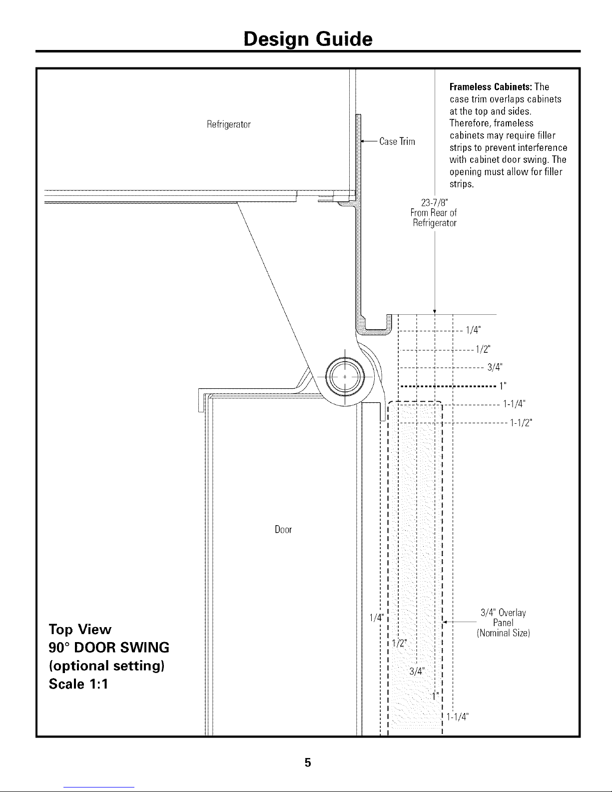
Design Guide
Refrigerator
Top View
90 ° DOOR SWING
(optional setting)
Scale 1:1
Door
CaseTrim
FramelessCabinets:The
case trim overlaps cabinets
atthe top andsides.
Therefore, frameless
cabinets may require filler
strips to prevent interference
with cabinet door swing. The
opening must allow for filler
strips.
23-7/8"
FromRearof
Refrigerator
' ' 1/4".... t .... i.... t--
i i
i i i
.... _ .... _ -- -- -- _ ..... 112
,,LiL ::
i i i .
................... 1 "
I ',:'::'_--I-1 --'_........... 1-1/
i
ell .....
, t .... _=t,--7-1--t ............. 1-1/2
i i
, I ,, ', ,, I ,,
,, I ,, !
,, I ,, I
i i | i
i i i | i
i i i i i
i i i i i
,, I ,, |
, I ' ' ' | '
i i i i
, I ' ' ' | '
i i
, , | ,
i i i i i
i I ' !
i 1 i i i
i i i i i
i i i | i
i i
i i i | i
i i i i i
' I ' ' | '
1 i i i i
I I 1 1 I ! 1
i i | i
i i i i i
i i i | i
i i i | i
i i i i i
i i i | i
.... I ...... 3/4 Overlay
I ,
' ' _ Panel
I i i i
i i " "
.... | (Nom,nalSize)
II' " " " I
1/2 ....
I ', ,' |
I ' ' !
I qt/l" ,,l
I _'C" ,, I
I , I
i
I 1',,!
I
I ! ,
I | 1-1/4"
I I
i
5
Page 6

Design Guide
CUSTOMIZATION BASICS:
Framed Or Overlay Panels, Custom Handles and Accessory Kits
Models Available
Stainless Steel Wrapped Models:
ZICS360N RH (right-handed door)
ZICS360N I,H (leli-handed door)
Trimmed models:
ZIC360N RH (right-handed door)
ZIC360N I,H (lett-handed door)
Overlay panels
You may also choose to install custom overlay panels
fl'om your cabinet manufacturer. This design provides
a seamless appearance which integrates smoothly with
surrounding cabinetr>
Stainless Steel Wrapped Refrigerators
Stainless Steel wrapped refrigerators have wrapped
doors and grille panel, beveled edges, and tubular
stainless steel handles that coordinate with other
Monogram appliances. These models are shii)ped
readv for installation.
Trimmed Refrigerators
Trimmed refrigerators are designed to be customized
with decorative panels. Field installed custom door
and grille panels are required.
Overlay Panel
Standard pacer Panel
Door Handle I/4" Thick Backer Panel
Standard supplied handles shown in 3/4" overlay panel position.
Framed panels
You may install 1/4" thick custom panels from your
cabinet manufacturer. The decorative panel slides
into the thctorv installed trim. Or, order black,
white and stainless steel accessory panels ti'om w)ur
Monogram dealer.
Door and Drawer Handles
The standard supplied handles can be a(!iusted to
accommodate both fl'amed or overlay panels. Custom
handles of your choice, supplied by your cabinet maker
can also be installed on overlay panels. If desired, you
may order ZKHCSS2 Monogram stainless steel tubular
handle kit tot 3/4" overlay panels.
Side Panels
Side panels must be used whenever the sides ol the
refl'igerator will be exposed.
StandardDoorHandle FramedPanel
Standard supplied handles shown in 1/4"panel position.
Optional Accessory Kits
• ZKHCSS2: Monogram Tubular Stainless Steel handles
designed to fit 3/4" overlay panels. This kit also
includes a handle side trim fi)r custom handles.
• ZUG2: For side-bwside installation of two trimmed
bottom-freezer refrigerators. This kit provides tot the
installation of a unified custom grille panel to span the
width of two units using a framed or oveday panel.
• ZUGSS2: For side-by-side installation of two stainless
steel wrapped bottom-ti'eezer refl'igerators. This kit
provides a unified stainless steel grille panel to span
the width of two units.
Accessory Panels
White, black and stainless steel accessory panels are
available fl'om your Monogram dealer. Panels are cut
to size and readv to install.
ZPBC360-Black, ZPWC360-X4'hite,
ZPSC360-Sminless Steel Panels
6
Page 7

Design Guide
1/4" FRAMED PANEL DIMENSIONS
If you choose to install framed panels, they must be
cut to tile dimensions shown. Tile panels will slide
into tile frame on tile door, drawer and ,rille
If tile custom panel is less than 1/4" thick and if it
fits loosely in tile door fi'ame, it can be backed up
with a piece of filler material or fi_am tape to
improve the fit.
Door
/ Reveal
I_A_I
[ GrillePanel ]_
FreshFood 1_
Panel
FreezerDrawer D
Panel
IMPORTANTNOTE:Maximum total panel
weight:
• Freshfood door panel-58 Ibs.
• Freezer drawer panel- 28 Ibs.
• Grille Panel- 11Ibs.
FramedPanel Dimensions
A (Width) B (Grille Height) C (FFHeight) D (FZHeight)
1/4"FramedPanel 33-7/8" 8-7/8" 46-1/16" 21-7/8"
OverlayPanel Dimensions
A (Width) B (Grille Height) C (FFHeight) D (FZHeight)
1/4"Backer Panel 33-7/8" 8-7/8" 46-1/16" 21-7/8"
0.10"Spacer Panel 32-1/2" 7-5/8" 44-11/16" 20-1/2"
3/4"Overlay Panel 34-1/8" 9" 46-5/16" 22"
3/4" OVERLAY PANEL DIMENSIONS
For a i/lore Ctlstoill _ll)l)e_lr_liice _ overlay l)_lnels Ill,IV be
installed on trimmed models. The overlay panel must
be secured to a 1/4" thick backer panel which slides
into the t_im. A spacer panel 0.10" thick must be
placed between the overlay and backer panel.
Assemble tile panels with glue and screws.
• Center the spacer panel on the backer panel, leit to
right and top to bottom. Secure the panels with glue.
• Center tile spacer and backer panel on the overlay
panel and secure with glue and screws. Screws must
be co/mtersunk into the backer panel.
Door/Drawer
\
\\
\
1/4"
Backer,. .
Panel_ _Spacer
IMPORTANTNOTE:Maximum
total weight for the assembled
panels:
• Fresh food door panel-58 Ibs.
• Freezerdrawer panel- 28 Ibs.
• Grille Panel- 11Ibs.
NOTE: I,eft-to-right oiiset is not always equal to
top-to-bottom oiiset.
Page 8

Design Guide
SIDE PANELS
Side panels must be used whenever the sides of the
refrigerator will be exposed. The 1/4" side panels
will slip into the side case trim. Secure the panels to
the refrigerator with stick-on hook and loop fastener
strips. Order the side panels fl'om the cabinet
I11[I n 11{;I ct t II'eI'.
• Gilt a notch in the top ti'ont corner as shown to
allow clearance for corner keys in the ti'ont side
[riill.
* Dei)ending, on
installation height.
ZUG2 GRILLE PANEL DIMENSIONS
The ZUG2 tmified grille panel kit provides for the
installation of a framed or o_erlay grille panel.
A
[ GrillePanel ]_
FramedPanel Dimensions
A (Width) B (Height)
1/4"Framed Panel 69-7/8" 8-7/8"
OverlayPanel Dimensions
A (Width) B (Height)
1/4"Backer Panel 69-7/8" 8-7/8"
0.10"Spacer Panel 68-1/2" 7-5/8"
3/4"Overlay Panel 70-1/8" 9"
i i
i i i
Assemble the o',erla)panels in the same manner as
the door and drawer panels.
8
Page 9

Installation Instructions
TOOLS REQUIRED
• Tinsnips to cut banding
• Stepladder
• Bucket
• i,evel
• Appliance Hand T_uck
• Tubing cutter
• 7/16" open-end wrench
• #9 Phillips screwdriver
• Drill and ai)propriate bits
• 5/]6", 7/16" socket
• Satety glasses
• l-I/4" open end wrench
• Plie_
• 1/4" ratchet
HARDWARE SUPPLIED
• X*Vaterfilter byl)ass plug
• Anti-Tip brackets
• 1/4" nut and teHule
MATERIALS REQUIRED
• 35" long 2x4 fl_r Anti-Tip support
• 1/4" COl)per water line tubing or GE
SmartConnecg" Refrigerator Tubing kits
• X_'ater sh ut-ofl wflve
• C/IStOIll panels tot fl'esh tood door, fl'eezer drawer
and grille panel
• Screws to secure refrigerator to cabinetry:
• Stick-on hook and loop fastener strips for
1/4" side panels
FLOORING
For proper installation, this refl'igerator must be
placed on a level sm'lace of hard material that is at
the same height as the rest of the flooring. This
sm'lace should be strong enough to support a flfllv
loaded refrigerator, or approximately 1,200 lbs.
NOTE: Protect tile finish of tile flooring. Cut a large
section of tile cardboard carton and place trader tile
refrigerator where you are working.
GROUNDING THE REFRIGERATOR
IMPORTANT_(Please read carefully)
FOIl PERSONAl, SAFETY, THIS APPI,IANCE MUST
BE PROPERI,Y GROUNDED.
Tile power cord of this appliance is equipped with
a 3-prong (gro/mding) plug which nlates with a
standard three-prong (grounding) wall receptacle
to minimize tile possibility of electric shock hazard
fl'om this appliance.
Have the wall outlet and circuit checked by a
qualified electrician to make sure tile outlet is
properly gro/mded.
OR REMOVE THE THIRD
(GROUND) PRONG FROM
THE POWER CORD.
Where a standard 2-prong wall outlet is encountered,
it is wmr personal responsibility and obligation to
have it replaced with a properly gro/mded 3-prong
wall outlet.
DO NOT, UNDER ANY _----9_I_
CIRCUMSTANCES, CUT
DO NOT USE AN ADAPTER PIJJG TO CONNECT
THE REFRIGERATOR TO A 2-PRONG OUTI,ET.
DO NOT USE AN EXTENSION CORD WITH THIS
APPI,IANCE.
9
Page 10

Installation Instructions
[STEP 1] REMOVE PACKAGING
CAUTION:Refrigerator is much hea, ier at the
top than at the botton/- be careflll when moxing.
X,_hen usim* a hand track, handle fl'om side onE.
PRUDENCE:Ce est pl.s
hmrd en haut qu'en bas. I1 taut 6tre prudent lots des
d@lacements. Si un diable est utilis& il taut soulexer le
r_frig&'ateur stu" le c6t_ seulement.
• Careflflly cut banding at the top and bottom,
relilove otKer carton.
• Slide out back corner posts (2).
• Slide carton ott top of cabinet.
NOTE: IT IS NOT NECESSARY TO I,AY CABINET
DOWN IN ORDER TO P,EMOVE SKID!
• The trait is secured to the skid with 4 slotted
tie-down straps. Remove the tOtu" 5/16" bolts fl'om
the base channels in the tie-downs.
J • Remoxe the four 7/16"
bolts secm'ing the straps
to the skid.
CAUTION:DONOT
ATTEMPT TO ROI,I,
UNIT OFF SKID.
Remove
Tie-Downs
/
PRUDENCE:ICNE
FAUT PAS ESSAYER DE
FAIRE ROUI,ER I,E
Rt_FI)d Gt_RATEUI). POUR
I/ENI,EVER DE lAY
PA1,ETTE.
• Sui)port blocks on the bottom of the refligeration
case must be removed before the refl'igerator is
taken off the skid or damage will occm'. Careflfll>
tilt refligerator and slide blocks out from beneath.
• Remove toekick. Set aside for final installation.
• I,ilt the refligerator off the skid with an appliance
dolly. Handle fl'om the sides.
[STEP 2] INSTALL WATER LINE
• A cold water suI)ply is required fin" automatic
icemaker operation. The water pressure must be
between 40 and 120 p.s.i.
• Route l/4" OD COl)per or GE Smart(:onnect '_
plastic tubing between house cold water line and
the water connection location.
• Tubing should be hmg enough to extend to the
fl'ont of the refl'igeratm: Allow enough tubing to
accommodate bend leading into the water line
connection.
NOTE: The only GE approved plastic tubing is
sui)plied in the GE Smart(:onnect '_ Refl'igerator
Tubing kits. Do not use any other plastic water sui)ply
line because the line is trader pressure at all times.
Other types of plastic may crack or Hq)ttu'e with age
and catlse water dalllage to voui" hollle.
GE Smart(]onnect ''_Refl'igerator Tubing Fdts are
available in the following lengths:
2' (.6 m) WX08X10002
6' (1.8 m) WX08X10006
15' (4.6m) WX08X10015
25' (7.6 m) _,\_X08X10025
Shut off the main water supply,
Turn on the nearest fimcet long enough to clear the
line of water.
• Install a shut-off \_d\'e between the icemaker water
valve and cold water pipe in a basement or cabinet.
The shut-off \Mve should be located where it will be
easily accessible,
_Copper Tubing
CompressionNut
SaddleType
ShutoffValve
Packing
Outlet Valve
Ferrule
(Sleeve)
NOTE: It is best to install the valve into a vertical
water pipe. If wm install the valve into a horizontal
water pipe, make the connection at the top or
side to avoid drawing off any sediment fl'om the
water pipe.
• Drill a 1/4" hole in the water pipe,
• Fasten the shut-off wdve to the pipe with pipe
clamp.
• Tighten the clamp screws tmtil the sealing washer
begins to swell. Do not overtighten.
• Place a compression nut and terlule (sleeve)
onto the end of the tubing and connect it to
the shut-off wdve, Make sm'e the tubing is fiflly
inserted into the wflve and terrule is tightened,
10
Page 11

Installation Instructions
[STEP 21(continued}
• Turn on the main water supply and flush debris.
Run about a quml ot water through the robing into
a bucket. Shut off water supply at the shut-offvalve.
NOTE: Saddle type shut-off \;flves are included in many
wamr supply kits. Befi)re purchasing, nlake sure a saddle
type \:live complies with vour local plumbing codes.
NOTE: (2ommonwealth of Massaclmsetts Plumbing
Codes 248CMR shall be adhered to. Saddle \:flves are
illegal and use is not pemfitted in Massachusetts.
Consult with your licensed plumbe_:
ISTEP 2AI WATER LINEINSTALLATION
WITH A REVERSEOSMOSIS SYSTEM
Skip thisstepwhen not usingan ROSystem
If the water supply to the refl_igerator is fl'om a Reve_e
Osmosis _4hter Svsteln use the refligerator's filter bypass
plug. Using tim reliigerator's water filtration cartridge
with the RO filmr can restflt in hollow ice cubes,
\
FilterBypassPlug
ISTEP31INSTALLSIDEPANELS
Skip this step when not using side panels
If _)tl are using 1/4" side panels, they should be inserted
into the case trim. Fasmn the panels to the refligerator
with stick-on hook and loop fi_stener strips beibre setting
reliigemtor in place.
11
I STEP 41 INSTALLANTI-TIP BRACKETS
WARNING:ANTI-TIP PRECAUTIONS
The refiJgerator is top-heavy and must be secured to prexent
the possibility of tipping fiwward.
ATFENTION:PRECAUTIONS CONTRE LES
BASCULEMENTS
Le r_tiig_ntteur est beattcoup phts lourd en haut et il iitut le
maintenir en place pour &iter la possibilit_ de son basculement
xers l'axant.
• Cttt a 2" x 4" x 35" block md secllle the block to the
motmtii_g, brackets [)roxided using,, #1,9 or #14 wood ....screws
2x4But _
35"Length
Installation Mounting
Height Bracket
FromFloor
ScrewsMountedintoj
VerticalWall Studs
• Secure the bracket xqtb wood block to the back x_allso that it
is 84" (or }our installation height) from the finished flOOl:
[lse #12 or #14 wood scre_s. See illustn_tiolL
Brackets
-- NotRequired
__ Beneatha
Height Soffit
From
Floor
to
Bottom
ofWood
Block
Brackets
Required
Block.
SideView
• Scl'e_:s n/ust penetnae at least one inch into _ertical wall
studs.
• Beibre pushing the reliJgerator into the opening, plug
the po_vr cord into the receptacle. Open the grille panel
and x_ach into the opening at the back to grasp the power
cord. Pull die I)O_r cord into tim opening asyou push the
refligemtor back.
• (;en@ push retiigemtor into the opening with hands ag;dnst
tI'oI/t COFI/eFS.
hnportantNote:Whentherefrigeratorisinstalledunderasoffitorifthereisnot
enoughheightforthismethodof security,bracketscannotbeused.Proceedtostep5
toleveltherefrigeratorandthentostep6tosecurerefrigeratortocabinets.The
refrigeratormustbesecuredtopreventtipping.
Page 12

Installation Instructions
[STEP 5] LEVEL REFRIGERATOR
All models have 4-point leveling. The front is
supported by leveling legs, the rear is supported by
a_!justable wheels. Both are accessible fl'om the fl'ont
of the refl'igerator.
• To level the back of the refl'igerator, tm'n the
7/16" hex nut located above the front wheels. Turn
clockwise to raise or counterclockwise to lower the
refl'igera tin,
• For fl'ont leveling, use a 1-1/4" open-end wrench.
• At!just height of refl'igerator to match installation
cutout opening 83-1/2 to 84-1/2". The refl'igerator
should be level and plmnb with cabinetry.
CAUTION:
The rear leveling wheels and fl'ont leveling legs are
limited to a maximmn height a_!justment of l ". If the
installation requires more than 84-1/2" height, the
installer should elew_te the refl'igerator on a sheet of
plywood or rtmne_. Cal)inetrv trim could also be
added across the top of the opening to shorten the
opening. If you attempt to raise the refrigerator
more thm_ 1", you will damage the front leveling legs
mid the rear leveling wheels.
PRUDENCE
I,es roues de nivellement arri&re et les pattes de
nivellement a\_mt permettent un r_glage maximal
de 25 mm (l po). Si l'ouverture pore" le rg_fl'ig_rateur
a tree hauteur supg_riem'e fi 2,15 m (84-1/2 po),
l'installateur doit _lever le r_fl'ig_rateur sin" tree
teuille de contre-i)laqu_ ou des glissi&res. 11est
_galement possible d'ajouter des baguettes de
finition des placards sur le haut de l'ouvertm'e afin
de la r_duire, i,ever le r_fl'ig_ratem" de plus de
25 mm (l po) endommage les pattes de nivellement
avant et les roues de nivellement artiste.
[STEP 6] SECURE REFRIGERATOR
TO CABINETRY
X4henexer possible, perfl_m_ this step for anti-tip
secm'ity, or when anti-tip brackets cannot be used.
The refrigerator must be secured to prevent tipping.
• Raise the grille panel to access case trim.
• Drill hole in trim and drive screw through the trim
into ac!jacent cabinet.
• Follow the same procedm'e on the opposite side.
DriveScrews
ThroughCaseTrimandInto
AdjacentCabinets
12
Page 13

Installation Instructions
[STEP 7] ADJUST DOOR SWING
NOTE: This refiigerator has a 2-position door stop.
When space does not allow the door to swing open
fldlv to 130 °, you may change the door swing to a 90 °
opening. Skip this step if door opening is satisfactory
for your installation situation.
• i,ift the grille panel to access the wire cover trim.
• Remove screws on both sides of the wire cover trim
and lift off.
• Use pliers to tlnsci'ew door stop and reinstall into
the 90 ° position.
I
Remove
Wire Cover
TrimScrews
<L..
W
9PinLocationFor
0° Door_ PinLocation
asShipped
130° DoorSwing
• Reinstall the wire cover trim.
[STEP 81 INSTALL GRILLE PANEL
• Raise the grill panel to stop position.
I
Loosen
Side
Trim _,
Screw
I
Grille]|l
__ P_
AdjustNutBelow
Springto Accommodate
PanelWeight
Loosen
Side
Trim
Screw
• i,oose screws on side trim behind fl'ame. Remove
bottom trim.
• Slide panel over the metal baker panel and into the
trim.
• If necessary, mp with a wood block tmtil panel slips
trader the top trim piece.
• Reassemble bottom trim. Tighten screws.
• A(!just the hinge spring to accommodate the panel
weight, if necessary.
13
Page 14

Installation Instructions
ISTEP 91 INSTALL FRAMED PANELS
Right hmad models shown. Use the same instructions
for left hand models.
IF YOU ARE INSTALLING OVERLAY PANELS,
GO TO STEP 9A.
UseFrontHoles
to SecureTrim
UseRearHoles
to SecureHandle
Handle
Trim
j DoorTrim
Refrigerator
Door
Standardsuppliedhandleshown
in 1/4" panelposition.
Install door and drawer panels:
• Open door to 90 °. Remove the 4 Phillips head screws
fl'om the door handle.
• Remove handle. Retain all screws.
• Relnove 4 screws holding triln, lili off trim.
Retain screws.
• Slide fl'amed panel into the door trim.
• There are two sets of holes in the handle side t_im.
Replace handle side trim by installing the original
screws in the FRONT screw holes.
• Secure the handle to the door using the REAR screw
holes.
• Follow the same procedm'es to install the drawer panel.
14
Page 15

Installation Instructions
[STEP 9A] INSTALL OVERLAY PANELS Right hand models shown. Use the same instructions
for left hm_d models.
Handle
Trim
Move
Forward
For3/4"
Panel
- UseFront Holes
to Secure Handle
UseRearHoles
to SecureTrim
DoorTrim
Refrigerator
Door
Suppliedhandleshowninthe
overlaypanelposition.
Install door and drawer panels:
• Open door to 90 °. Relnove the 4 Phillips head screws
ti'om the door handle.
• Remove handle. P,emin all screws.
• Remove 4 screws holding trim, lilt off trim.
Retain screws.
• Slide overlay panel into the door trim.
• There are two sets of holes in the handle side trim.
Replace handle side trim by installing the original
screws in the REAR screw holes.
• Secure the handle to the door using the FRONT screw
holes.
• Follow the same procedures to install the drawer panel.
Custom handles
If you are using custom handles, the handle must be
properly secm'ed to the panel betore sliding the panel
into the trim,
• The cabinet manufacturer will supply the custom
handle and hardware.
• Secm'e the door/drawer trim using both the FRONT
and I/EAR screw holes. Discard supplied handle.
15
Page 16

Installation Instructions
[STEP 10]CONNECT WATER SUPPLY
L[
• i,ocate and bring tubing to the fl'ont of the cabinet.
• Turn the water oil to flush debris frmn line. Run
about a quart of water through tubing into a bucket,
then shut off wa te r.
Copper Tubing:
• Slip a 1/4" nut and tbHule (provided) over both
ends of the COl)per tubing. Insert tube into the
tmion fitting on the trait and tighten nut to union.
• Tm'n on the water to check fin" leaks.
GE SmartCommct'" Tubing:
• Insert the molded end of the tubing into the
refrigerator connection. Tighten the compression
nut until it is just hand tight.
• Tighten one additional turn with a wrench.
Overtightening can cause leaks!
• Tm'n on the water to check for leaks.
Note: Make sure excess tubim*_ length does not
interfere with drawer closim* or toekick installation.
ISTEP 11] CONNECT POWER
• Check to be sm'e tile power cord is phlgged into
the receptacle.
:L.
Raise"N
Grille]1!
Panel_]
4
Electrical MasterLight
Outlet Switch
• Check to make sm'e power to refl'igerator is on by
opening refl'igerator door to see if interior lights
are Oil.
• The temperature controls are preset at 37°F
fin" the fl'esh food section and 0°F fin" the freezer.
• Allow 24 horn's to stabilize before making
a({j ustm ents.
lSTEP 121START ICEMAKER
i
PowerSwitch
o
• Flip the switch to I (ON). The icemaker will begin
operation automatically.
• Be sm'e nothing interteres with the sweep of the
feeler arm.
• Discard the first fidl bucket of ice cubes.
• To tm'n the icemaker off, set the switch to O (OFF).
16
Page 17

Installation Instructions
ISTEP 131 INSTALL TOEKICK
• I,ocate the supplied toekick (shipped taped to
the side of the refl'igerator), Install with 2 screws
provided, a_!iust to desired height and tighten
screws,
• A custom toekick can be installed to match or
complement the surrounding cabinetry, Llse the
supplied toekick as a template to cut out the notch
and vent holes,
SuppliedToekick
1/4" or Thicker Toekick
Importm_t: The xented toekick must remain
unobstructed fi)r proper air circulation and
refl'igerator operation,
17
Page 18

Notes
18
Page 19

Notes
19
Page 20

NOTE:While performing installations described in this book,
safety glasses or goggles should be worn.
t'_n"Mo_wg'r,m °° Iocnl ._vic_, ht your (m_,, c(lfl
l. 800.444. 1845.
NOTE: Pl-o(ltlc[ iln[)l-()'¢( mt_lll is _ contimfing ,:m,:l( ;avov ;_t
(;en(:r_d Ele(tri(:. Therefor(, mar(:rials, ;q)l)(m-an(t and
sl)(_tifi(alions ar(_ sul)je(t to (hang(: v.illlotll noli(t.
Pub.No.49-60136-2
Dwg.No. 164D4371PO01
11_03JR
15421-I
Monogram:
GEConsumer Pro_c_
General _ec_c _mpany
Louis_H_ KY40225
© 2_3 General _ec_c Company
 Loading...