

Page 1

GE Consumer & Industrial
XXR
Q
H
O
T
VE
R
Y
H
O
T
LEFT
SIDE
RIGHT
SIDE
NO
T
SO
H
O
T
XBEW
Y
W
ARM
XQM
A
H
O
T
XX
R
Q
H
O
T
VE
R
Y
H
OT
NO
T
SO
H
O
T
XBEW
Y
W
ARM
XQM
A
H
O
T
LEFT
SIDE
RIGHT
SIDE
REALL
Y
H
O
T
Technical Service Guide
April 2008
Profi le and Monogram
30- and 36-in.
Induction Cooktop
31-9164
PHP900
PHP960
ZHU30
ZHU36
GE Appliances
General Electric Company
Louisville, Kentucky 40225
Page 2

IMPORTANT SAFETY NOTICE
!
The information in this service guide is intended for use by
individuals possessing adequate backgrounds of electrical,
electronic, and mechanical experience. Any attempt to repair a
major ap pli ance may result in personal injury and property
damage. The man u fac tur er or seller cannot be responsible for the
in ter pre ta tion of this in for ma tion, nor can it assume any liability in
connection with its use.
WARNING
To avoid personal injury, disconnect power before servicing
this prod uct. If electrical power is required for diagnosis or test
purposes, disconnect the power immediately after performing the
necessary checks.
RECONNECT ALL GROUNDING DEVICES
If grounding wires, screws, straps, clips, nuts, or washers used to
complete a path to ground are removed for service, they must be
returned to their original position and properly fastened.
GE Consumer & Industrial
Technical Service Guide
Copyright © 2008
All rights reserved. This service guide may not be reproduced in whole or in part
in any form without written permission from the General Electric Company.
– 2 –
Page 3

Table of Contents
Appearance Defects ........................................................................................................................................................21
Component Locator Views ...........................................................................................................................................17
Control Features ................................................................................................................................................................ 8
Cooktop Components ..................................................................................................................................................... 21
Cooktop Removal From Countertop ........................................................................................................................21
Diagnostics and Service Information ......................................................................................................................31
Elements ...............................................................................................................................................................................22
Fans .........................................................................................................................................................................................30
Filter Board ..........................................................................................................................................................................29
Generator Boards .............................................................................................................................................................28
Glass Maintop ..................................................................................................................................................................... 22
Heat Shield ........................................................................................................................................................................... 26
Installation ........................................................................................................................................................................... 7
Introduction ......................................................................................................................................................................... 4
Introduction to Induction Cooking ............................................................................................................................ 6
LINbus Connectors ........................................................................................................................................................... 27
Nomenclature .................................................................................................................................................................... 5
Operation Overview .........................................................................................................................................................16
Schematics and Wiring Diagrams ............................................................................................................................33
Thermal Cut-out ................................................................................................................................................................28
Touch Board ........................................................................................................................................................................23
Warranty .............................................................................................................................................................................. 35
– 3 –
Page 4
Introduction
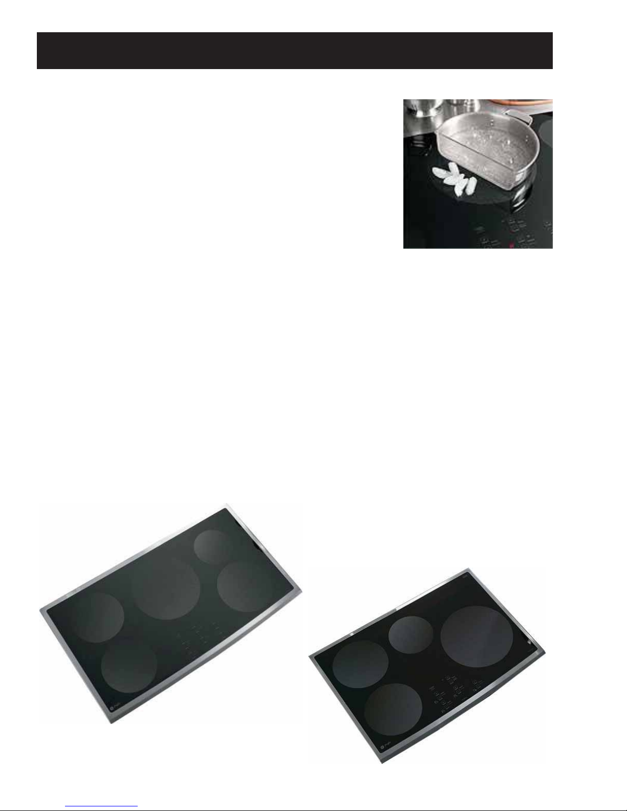
Introducing GE Profi le and GE induction cooktops―
offering fast, effi cient cooking.
Induction cooktops provide unmatched cooking performance and
fl exibility. Induction technology heats only the pan and its contents and
offers energy effi ciency by reducing wasted heat when compared to
radiant and gas cooktops.
The new Monogram and Profi le, 30- and 36-in. Induction Cooktops have
the following new features:
Innovative technology• ―delivers the responsiveness of a gas cooktop.
Superior performance• ―Induction technology heats only the pan and
its contents, providing an incredibly fast boil time.
Remarkable versatility• ―This induction cooktop offers the choice of 19 different power levels, including
a 3700-watt, 11" element for large cookware ( the highest wattage induction element in the industry*),
warming capability, and a low-heat simmer setting for delicate sauces.
Cooler cooktop surface• ―Since there is not a traditional thermal heating element, the induction cooktop
stays cooler than conventional radiant cooktops.
Below cooktop venting• ―that dissipates heat, permitting less depth to the burner box.
Easy cleanability• ―Cooktop cleaning is easier since spills and splatters do not burn on the cooktop.
Distinguished appearance• ―Sleek cooktop fi ts fl ush with the countertop, and is surrounded completely
in full-frame stainless steel trim. This cooktop can be installed above a GE® or GE Profi le™ wall oven.**
The four-burner models feature 1 ten-inch, 3700 W element, 2 seven-inch, 2500 W elements, and 1 six-inch
1800 W element. And with the 36-in. models, you get the addition of 1 eight-inch, 3200 W element.
*Among leading manufacturer brands
**Not to be installed over wall ovens with Trivection® technology
– 4 –
Page 5
Profi le Model Number
Nomenclature
P H P 9 0 0 D 1 M B B
Brand
P = Profi le
H = Induction
P = Cooktop
Feature Pack
900 = 30-in. Width
960 = 36-in. Width
Monogram Model Number
Brand
Z = Monogram
H = Induction
U = Cooktop
Feature Pack
30 = 30-in. Width
36 = 36-in. Width
D = Color
S = Stainless
Z H U 30 R B M 1 B B
Control Type
R = Digital
Color Code
BB = Black on Black
SS = Stainless Steel
Model Year
M = 2007
Engineering Digit
1 = 1st Version
Color Code
BB = Black on Black
SS = Stainless Steel
Engineering Digit
1 = 1st Version
Model Year
M = 2007
B = Black
S = Stainless
PHP960 Model shown
Mini-Manual
Nomenclature
The nomenclature plate is located under the
cooktop.
The mini-manual is located inside the
burner box and is accessed by removing the
electrical cover on the bottom of the cooktop.
– 5 –
Serial Number
The fi rst two numbers of the serial number
identify the month and year of manufacture.
Example: AR123456S = January, 2008
A - JAN 2008 - R
D - FEB 2007 - M
F - MAR 2006 - L
G - APR 2005 - H
H - MAY 2004 - G
L - JUN 2003 - F
M - JUL 2002 - D
R - AUG 2001 - A
S - SEP 2000 - Z
T - OCT 1999 - V
V - NOV 1998 - T
Z - DEC 1997 - S
The letter des ig nat ing
the year re peats every
12 years.
Example:
T - 1974
T - 1986
T - 1998
Page 6
Introduction to Induction Cooking
How Induction Cooking Works
Induction cooking uses high frequency (20-50 K hz)
magnetic energy to heat a ferrous metal pan when
it is placed over the induction coil. The induction
fi elds have no affect on non magnetic surfaces
such as paper, plastic, or non ferrous metals like
aluminum, or copper. Thermal sensors under the
glass surface communicate with microprocessor
controls for pan sensing and turn-down.
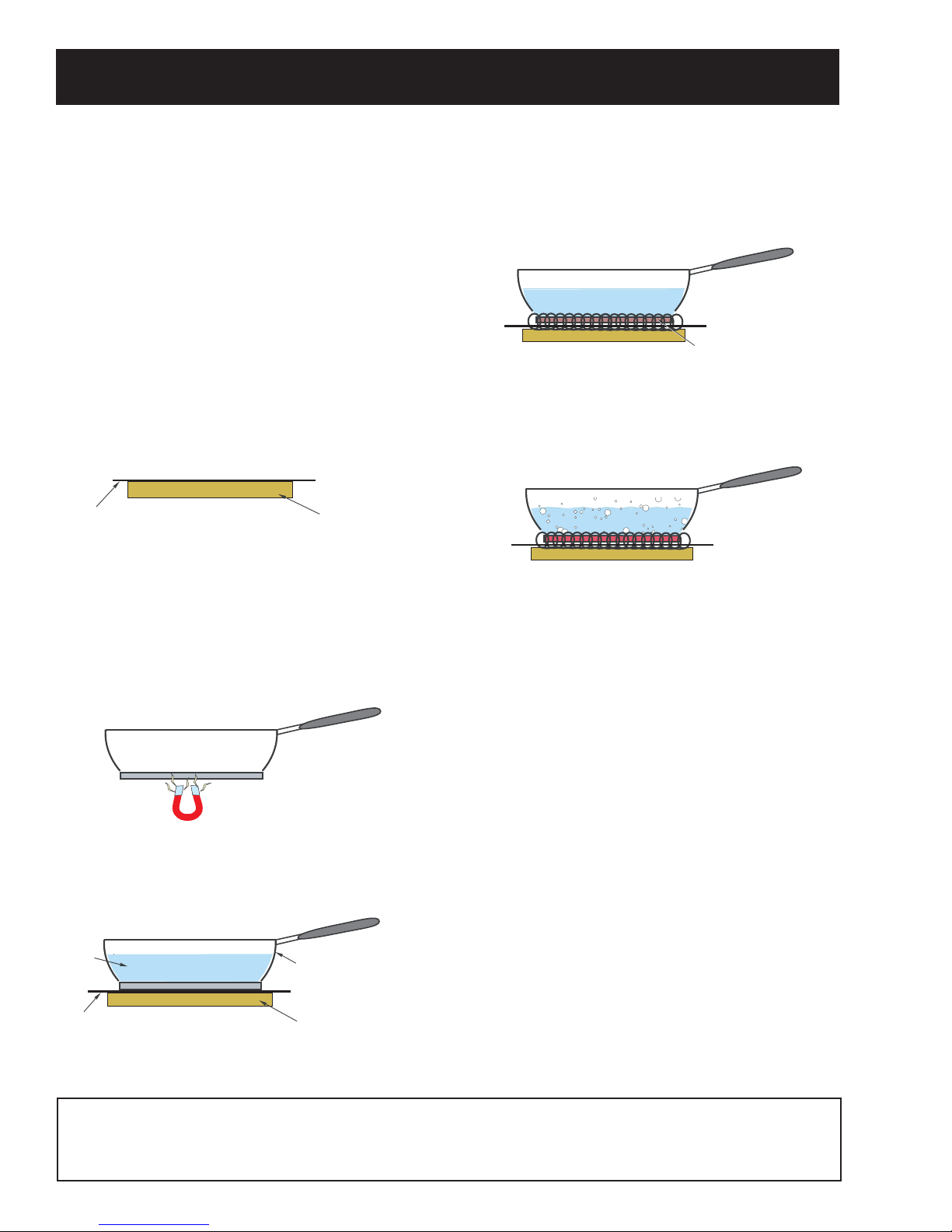
Part one: Coil produces electromagnetic energy
The fi rst component needed is an induction coil or
element. The induction coil generates the magnetic
fi eld needed for induction cooking.
Glass Cooktop Surface
Induction Coil
Part two: Pan uses the energy to produce heat
The second component is the ferromagnetic cooking
pan with a bottom constructed of material that will
attract a magnet. If a magnet will not stick to the
bottom of the pan, it can not be used for induction
cooking.
created by the induction coil is applied to only the
bottom of the pan.
Induction Fields
The contents of the pan are therefore heated more
quickly than they would be if heated by a gas
fl ame or a traditional radient heating element.
By heating only the bottom of the pan, the
surrounding surface remains cooler than with
traditional cooktops.
Features:
Testing Bottom of Pan with Magnet
Easy cleanability• ―Cooktop cleaning is easier
since spills and splatters do not burn on the
cooktop, which is about 500°F vs 1200°F for
radiant.
Control and responsiveness equal to gas• ―
This induction cooktop give you instant control
When the proper type of pan is placed over an
of the amount of heat added to the cookware.
energized induction coil, a fi eld of magnetic waves
will cause the bottom of the pan to heat.
Fast and Powerful• ―providing an incredibly
fast boil time. 3700 w, 8.5 min. to boil vs 12 to
14 min. for radiant and 14 to 16 min. for gas
Water
Glass Cooktop Surface
Pan with Bottom of
Magnetic Material
Induction Coil
(18k BTU).
Effi cient performance• ―Induction technology
heats only the pan and its contents, not the
kitchen. Effi ciency ratings are: Induction 83%,
Radiant 72%, and gas 38%.
Induction cooking is very effi cient. The energy
Note: There are no health risks associated with the use of this cooktop. The RF fi eld from an induction
element dies away to almost nothing at a distance of about one foot (30 centimeters). You will not receive
even trivial radiation from an induction cooktop unless you spend a long time well within one foot of an
operating element.
– 6 –
Page 7
Installation
r
WARNING: Before beginning the installation,
switch power off at the service panel and lock the
service disconnecting means. When the service
disconnecting means cannot be locked, securely
fasten a warning tag to the service panel.
Note: The complete installation instructions are
inclosed with the Use and Care Manual. Carefully
read and follow these instructions.
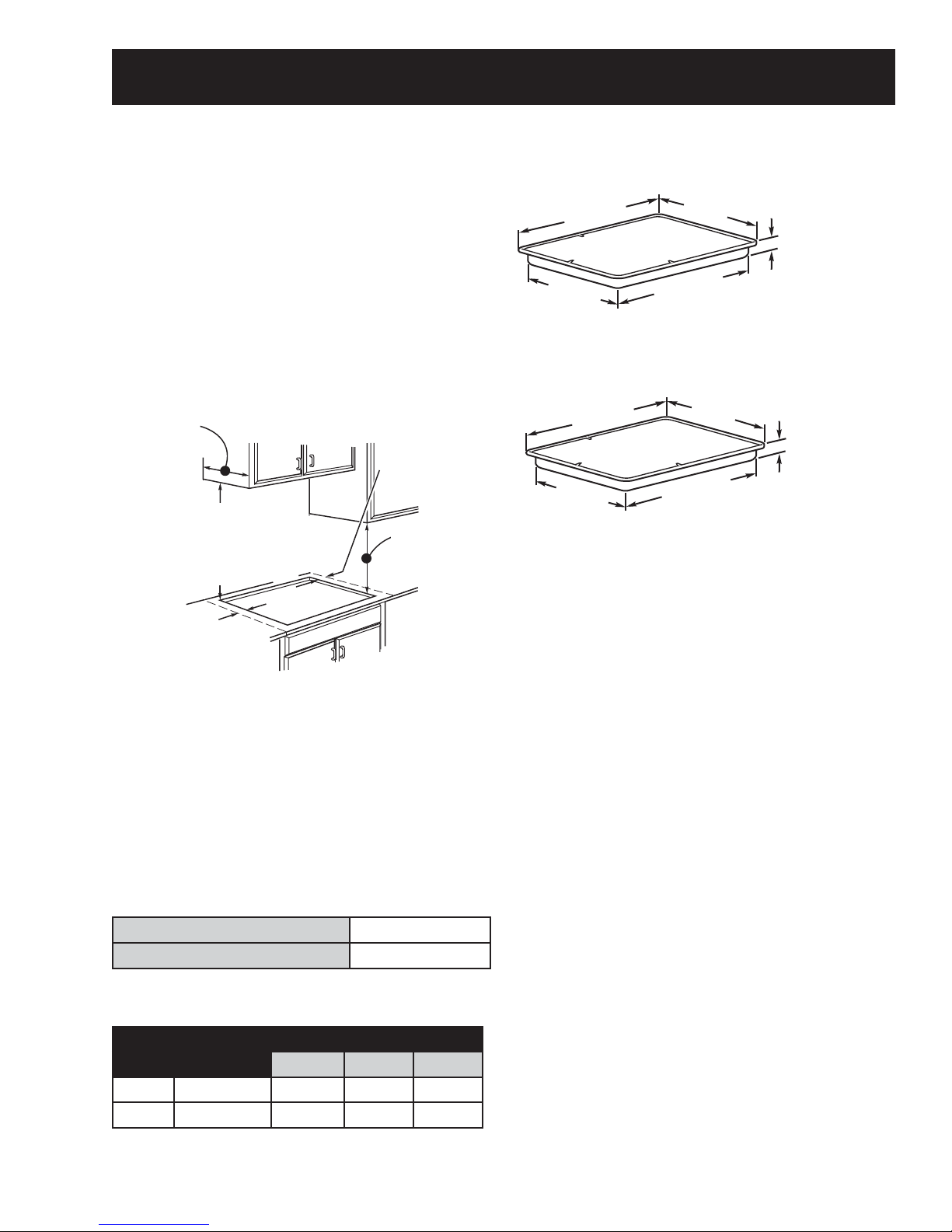
The following minimum clearance dimensions must
be maintained.
13″ MAX. Depth of uprotected
overhead cabinets
30″ MIN.
Clearance from
countertop to
unprotected
overhead surface
2″ MIN. Clearance
from cutout to side
wall on the left of
the unit
2″ MIN. Clearance
from cutout to
side wall on the
right of the unit
15″ MIN. Height
from countertop to
nearest cabinet on
either side of unit
If a 30-in. clearance between the cooking surface
and overhead combustible materials or metal
cabinets cannot be maintained, a minimum
clearance of 24-in. is required and the underside of
the cabinets above the cooktop must be protected
with not less than 1/4-in. insulating millboard
covered with sheet metal not less than 0.0122-in.
thick.
Grounding Specifi cations
Models PHP900 and ZHU30
29-3/4″
(29-7/8″ SS)
Cooktop
19-3/8″
21-3/8″
(21-1/2″ SS) at center
28-1/4″
4-5/8“ at front
baffle
3-1/4” at rear ai
intake
Models PHP960 and ZHU36
(36-1/8″ SS) at center
36″
Cooktop
18-7/8″
20-7/8″
(21″ SS) at center
33-5/8″
4-5/8“ at front
baffle
3-1/4” at rear air
intake
Power Supply
The cooktop must be connected to a supply circuit
of the proper voltage and frequency as specifi ed
on the rating plate. Wire size must conform to the
National Electrical Code or the prevailing local code.
The rating plate is located on the bottom of the
burner box.
Wiring
Built-in power leads are UL-approved for connection
to larger gauge household wiring. The insulation of
these leads is rated at temperatures much higher
than the temperature rating of household wiring.
The current-carrying capacity of a conductor is
governed by the temperature rating of the insulation
around the wire rather than the wire gauge alone.
Ground Path Resistance
Insulation Resistance
.
Overcurrent Protection
Maximum Kilowatt Rating
Size NEC Rating
30-in. 40 Amp 8.3 9.4 9.6
36-in. 50 Amp 10.4 11.8 12.0
The branch circuit load for one counter-mounted
cooktop is the rating on the nomenclature plate.
208V 236V 240V
0.10Ω Max.
205KΩ Min.
WARNING: Improper connection of aluminum house
wiring to these copper leads can result in a serious
problem. Use only connectors designed for joining
copper to aluminum and follow the manufacturer's
recommended procedure closely.
Ceramic Glass Cooktop
If the glass is damaged, it may be replaced as a
separate part. The touch board and electronics are
separate parts.
– 7 –
Page 8
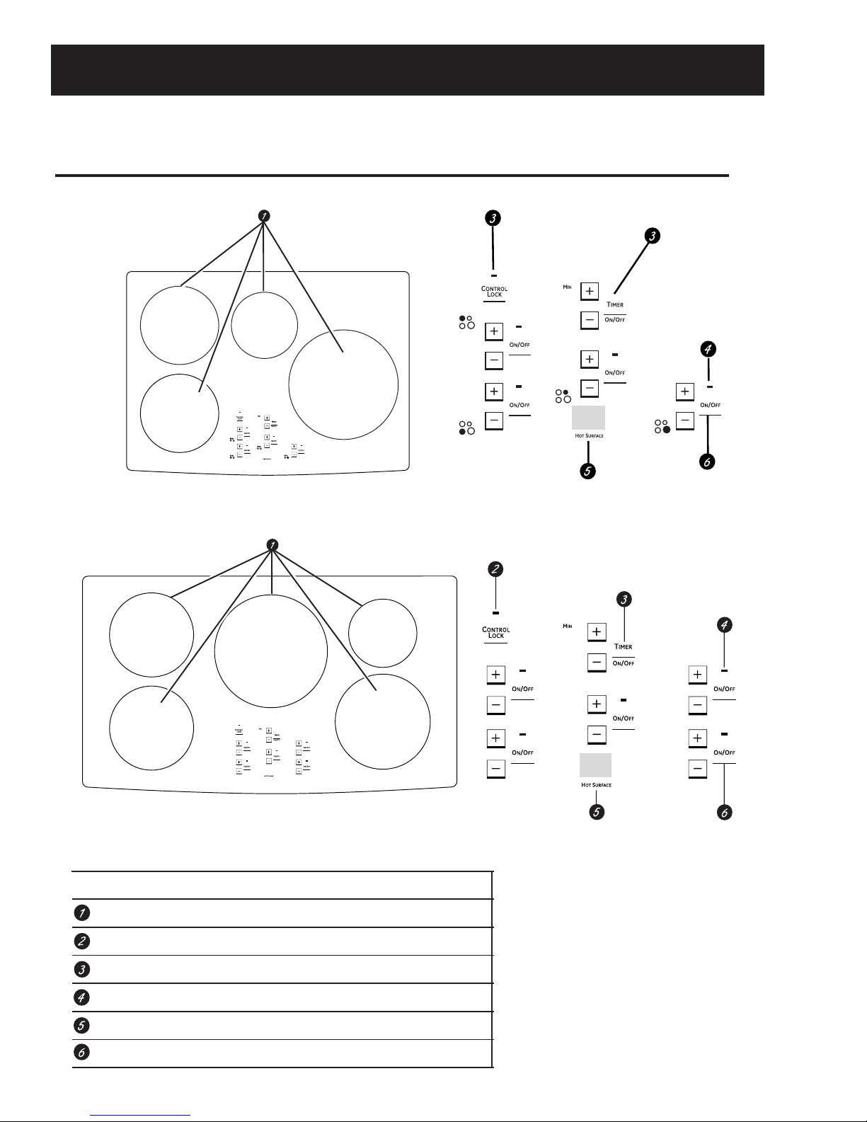
Control Features
Features of your cooktop.
Throughout this manual, features and appearance may vary from your model.
PHP900 30″ Cooktops
PHP960 36″ Cooktops
NOTE: 30” models have cooking element location
indicators next to each control.
Feature Index (Features and appearances may vary.) Explained on page
Cooking Elements 10
Control Lock 13
Kitchen Timer 12
ON Indicator Light (one for each element) 10
Hot Surface Indicator Light Area 12
Cooking Element ON/OFF Control 10
– 8 –
Page 9
How induction cooking works. ge.com
Min. Size
Use the minimum size pan for
the element. The pan material is
correct if a magnet sticks to the
bottom.
5-3/4” Min. Dia.
Pan Size
5-3/4” Min. Dia.
Pan Size
The elements beneath the cooking
surface produce a magnetic field that
causes the electrons in the ferrous
metal pan to vibrate and produce
heat.
The cooking surface itself does not
heat. Heat is produced in the cooking
pan, and cannot be generated until a
pan is placed on the cooking surface.
When the element is activated, the pan
begins to heat immediately and in turn
heats the contents of the pan.
4-3/4” Min. Dia.
Pan Size
7” Min. Dia.
Pan Size
Magnetic induction cooking requires
the use of cookware made of ferrous
metals—metals to which magnets will
stick, such as iron or steel.
Use pans that fit the element size.
The pan must be large enough for the
safety sensor to activate an element.
The cooktop will not start if a very
small steel or iron utensil (less than
the minimum size across the bottom) is
placed on the cooking surface when
the unit is turned on—items such as
steel spatulas, cooking spoons, knives
and other small utensils.
Using the correct size cookware
Each cooking element requires a MINIMUM pan
size. If the pan is properly centered, and of the
correct material, but is too small for the cooking
element, the element cannot be activated. The
display will flash “F” along with the power level
selected.
Cookware larger than the element ring may be
used; however, heat will only occur above the
element.
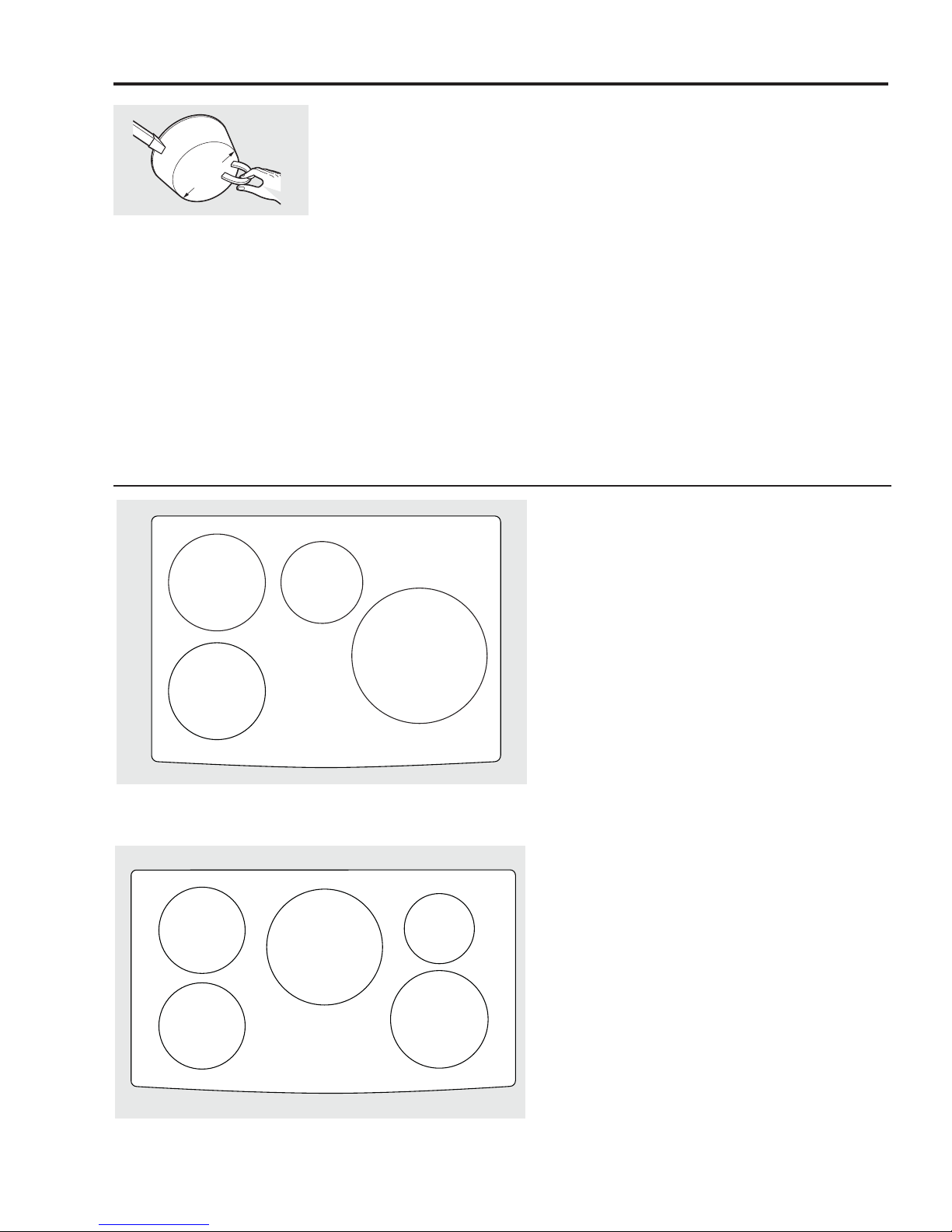
30” Wide Cooktop. Use the minimum size pan shown for each cooking
element.
5-3/4” Min. Dia.
Pan Size
5-3/4” Min. Dia.
Pan Size
36” Wide Cooktop. Use the minimum size pan shown for each cooking
element.
7” Min. Dia.
Pan Size
4-3/4” Min.
Dia. Pan Size
7” Min. Dia.
Pan Size
For best results, the cookware must make FULL
contact with the glass surface.
Do not allow the bottom of the pan or cookware to
touch the surrounding metal cooktop trim or to
overlap the cooktop controls.
For best performance, match the pan size to the
element size. Using a smaller pot on a larger burner
will generate less power at any given setting.
– 9 –
Page 10
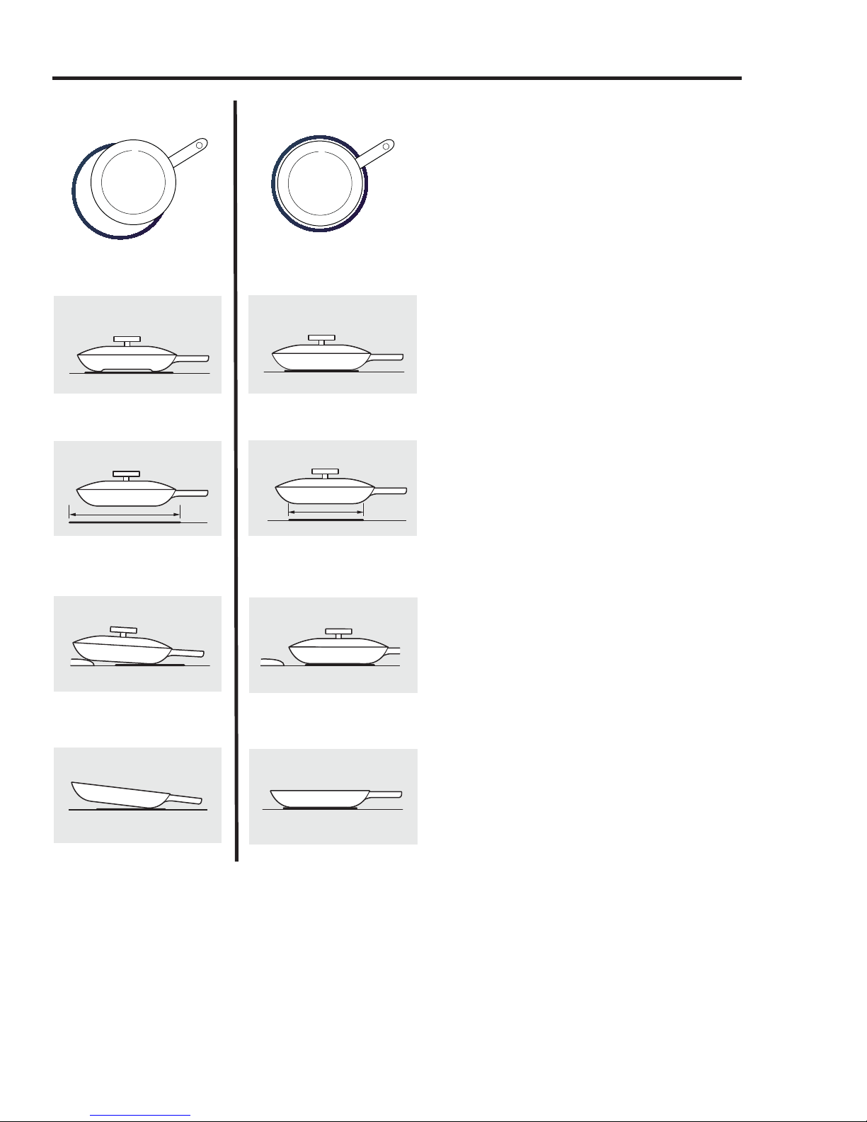
Choosing the correct cookware to use.
INCORRECT
Cookware not centered on cooking
element surface.
Curved or warped pan bottoms
or sides.
CORRECT
Cookware centered correctly
on cooking element surface.
Flat pan bottom.
Cookware recommendations
Cookware must fully contact the surface of the
cooking element.
Use flat-bottomed pans sized to fit the cooking
element and also to the amount of food being
prepared.
CAUTION:
■ The cooking elements may appear to be cool while
turned ON and after they have been turned OFF.
The glass surface may be HOT from residual heat
transferred from the cookware and burns may occur.
■ DO NOT TOUCH HOT COOKWARE or PANS directly
with hands. Always use mitts or pot holders to
protect hands from burns.
■ DO NOT SLIDE cookware across the cooktop
surface. Doing so may permanently damage the
appearance of the ceramic cooktop.
Pan does not meet the minimum
size required for the cooking
element used.
Pan bottom rests on cooktop trim
or does not rest completely on the
cooktop surface.
Heavy handle tilts pan.
Pan size meets or exceeds the
recommended minimum size
for the cooking element used.
Pan bottom rests completely on the
cooktop surface.
Pan is properly balanced.
– 10 –
(Continued next page)
Page 11
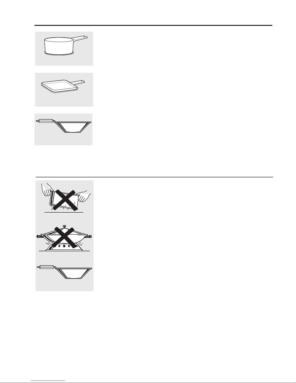
Use flat-bottomed pans.
Use a griddle.
Use a flat-bottomed wok.
Suitable Cookware
Use quality cookware with heavier
bottoms for better heat distribution
and even cooking results. Choose
cookware made of magnetic stainless
steel, enamel coated cast iron,
enameled steel and combinations
of these materials.
Some cookware is specifically
identified by the manufacturer for use
with induction cooktops. Use a magnet
to test if the cookware will work.
Flat-bottomed pans give best results.
Pans with rims or slight ridges can be
used.
Round pans give best results. Pans
with warped or curved bottoms will
not heat evenly.
For wok cooking, use a flat-bottomed
wok. Do not use a wok with a support
ring.
Cookware “noise”
Slight sounds may be produced by
different types of cookware. Heavier
pans such as enameled cast iron
produce less noise than a lighter
weight multi-ply stainless steel pan.
The size of the pan, and the amount
of contents, can also contribute to
the sound level.
When using adjacent elements that are
set at certain power level settings,
magnetic fields may interact and
produce a low whistle or intermitted
"hum". These noises can be reduced or
eliminated by lowering or raising the
power level settings of one or both of
the elements. Pans that completely
cover the element ring will produce less
noise.
A low “humming” noise is normal
particularly on high settings.
Do not place wet pans
on the glass cooktop.
Do not use woks with support
rings on the glass cooktop.
Use flat-bottomed woks
on the glass cooktop.
For Best Results
■ Do not place wet pans or lids on the
cooking surface or induction rings.
■ Do not place wet fingers on the glass
cooktop. Wipe up spills on the controls
with dry hands.
■ Do not use woks with support rings. This
type of wok will not heat on an induction
element.
■ Use only a flat-bottomed wok, available
from many cookware manufacturers.
The bottom of the wok should match the
diameter of the induction ring to insure
proper contact.
■ Some special cooking procedures
require specific cookware such as
pressure cookers, deep-fat fryers, etc.
Cookware with flat bottoms that match
the size of the surface element being
used will produce the best results.
– 11 –
Page 12

Setting the controls.
Using the Touch Control.
Touch the pad lightly with the flat part
of your fingertip. Touch the center of the
pad to ensure the cooktop response.
Operating the Cooking Elements
A "beep" sound can be heard with each
touch to any pad.
1/2
The power level with a fraction
indicates the additional half-step
setting.
Each of the cooking elements have
separate ON/OFF pads and LED display.
Be sure to use cookware that meets the
minimum pan size requirements.
To turn on a cooking element:
Place a pan with food onto the
induction element. The pan size
should match the indicator ring.
Touch the ON/OFF pad. “5” will flash
in the display.
Touch the (+) or (-) pad to select power
level and to activate the induction
element. A sound will beep. The (+) or
(-) pad must be pressed within 10
seconds to activate the element.
NOTE: You can also touch and hold the
pad to scroll quickly to the desired setting.
Power Level Settings
The cooktop offers 19 power levels,
including a Boost setting. Power levels
range from “L” to 9 in precise half-step
increments. For example: 1, 1-1/2, 2,
2-1/2 and up to power level 9.
Power Level “L”, the lowest setting, is
recommended for “Keep Warm.”
The induction circuit detects the pan and
allows the element to be activated. Both
the element ON indicator light and the
cooktop HOT SURFACE light will illuminate.
If no power level is selected within 10
seconds, the zone will be deactivated.
To turn the control to OFF, touch the
ON/OFF pad. The induction element will be
turned off and the display will be blank.
With an element control ON:
If a pan is removed or moved to off-center
from the cooking ring, the control will flash
“F” along with the power setting. After 30
seconds, the element will be deactivated
and displays will turn off.
If the pan is placed back on the zone
within 30 seconds, the flashing will stop
and cooking will resume.
The power level increases one-half level
with each touch.
Power level 9 is the highest normal
power setting.
Flashing “F” in the Display
If a pan is removed or moved off-center
from the cooking ring during the
cooking process, the control will flash
“F” along with the power setting. The
flashing "F" indicates that the pan is no
longer detected. After 30 seconds, the
element will be deactivated and the
display will turn off.
If the pan is returned to the surface
element within 30 seconds, the flashing
“F” will disappear and cooking will
resume.
(Continued next page)
– 12 –
Page 13

“H” indicates that the Boost power
level has been selected for rapid
cooking and boiling.
Boost Setting
Boost is the highest power level, designed
for large quantity rapid cooking and
boiling. Boost will operate for a maximum
of 10 minutes. After 10 minutes, it will
automatically revert to power level 9.
Boost may be repeated after the initial
10 minute cycle.
CAUTION: Do not leave a pot unattended
while in the Boost Mode.
To start the Boost power setting:
Place a pan matching the size of the
induction element over the selected
indicator ring.
Touch the ON/OFF pad. “5” will flash
in the display.
Touch and hold the (+) pad until the
display reads “H.”
Power Sharing
Four burner cooktops are divided into two separate
heating zones. The right and left side cooking zones
are powered by separate and independent induction
generators. One generator controls 2 elements, or two
cooking zones within a heating section share the power
of one generator.
NOTE: If the pan is removed, the display
will flash “F” alternating to “H”. After 30
seconds, the elements will turn off
automatically.
Sounds you may hear:
You may hear a slight “buzz” sound when
cooking with the Boost or high mode. This
is normal. The sound depends on the type
of pot being used. Some pots will “buzz”
louder depending on the material. A “buzz”
sound may be heard if the pan contents
are cold. As the pan heats, the sound will
decrease. If the power level is reduced, the
sound level will go down.
4 burner cooktops with right and left side (2) induction generators.
5 burner cooktops with right, left and center (3) induction generators.
Five burner cooktops are divided into 3 zones. The
right and left side have separate cooking zones and the
large center element is another separate cooking zone.
Power Sharing is activated when both elements in the
same cooking zone are activated and one element is
set for Boost (H). The element that is not set for Boost
will change to a lower power level. This is called
Power Sharing. When Boost operation is complete
(10 minutes), the other element may be reset to any
power level. Both elements can operate simultaneously
at normal power level settings of “L” to 9.
IMPORTANT NOTE FOR FOUR BURNER MODELS:
The elements on the right side share one generator.
Both elements can operate at any non-Boost (level L
to 9) power level at the same time. If the large front
element is set for "H" or Boost, the smaller element
at the right rear will be deactivated or turned off
automatically. The smaller right rear element can be
activated and set for any power level after the Boost
operation of the larger element is completed (10
minutes).
– 13 –
(Continued next page)
Page 14

Using the "L" Low Setting
Place a pan with food onto the
induction element. The pan size
should match the indicator ring.
The Low setting will keep hot, cooked food
at serving temperature. Always start with
hot food. Do not use to heat cold food.
CAUTION: Do not warm
food on the “L” power level
for more than two hours.
Touch the ON/OFF pad. “5” will flash
in the display.
Touch the (-) pad until the display
reads “L.” A sound will beep.
Do not use plastic wrap to cover food.
Plastic may melt onto the surface and be
very difficult to remove.
Use only cookware recommended for
this cooktop.
Using the Kitchen Timer
NOTE: Use the kitchen timer to measure
cooking time or as a reminder. The kitchen
timer does not control the cooking
elements.
Touch the Timer ON/OFF pad.
Touch the (+) or (-) pad to choose the
desired number of minutes. When the
(+) or (-) pad is held for several
seconds, the timer will increase or
decrease at a faster rate. The timer will
automatically start to count down the
minutes you have selected within 5
seconds of the last entry. The display
will show the minutes and a “
will flash.
.“
Placing uncooked or cold food on surface
element set for Low could result in foodborne illness.
For best results, all food set for Low should
be covered with a lid or aluminum foil.
Pastries or breads should be vented to
allow moisture to escape.
Always use pot holders or oven mitts when
removing food from the element set for
Low as cookware and plates will be hot.
The timer displays minutes remaining
until it reaches one minute. At one
minute, the timer will beep and start
counting down seconds.
With one minute remaining, the timer
will beep every 10 seconds. When all
time has counted down, the timer will
signal a long beep and the display will
become blank.
Touch the ON/OFF pad to turn the timer
off at any time. Touch (+) or (-) to add or
subtract to the set time.
Hot Surface Indicator Light
A HOT SURFACE indicator light (one for each
cooking element) will glow immediately
when any element is activated. The
indicator light(s) glow when the glass
surface is hot, and will remain on until the
surface has cooled to a temperature that is
safe to touch.
– 14 –
Page 15

Using the surface elements. ge.com
Error Alerts (Flashing “E”/”c” and “E” “o”)
Error alerts indicate a temporary problem
that may be corrected by the user.
Clear Keypad—If the display flashes “E”
alternating to “c”, the keypad is sensing
continuous activation of one or more
keypads. Clean or clear any obstructions
on the keypad area. Obstructions may be
water, food spills, a utensil or other objects.
To resume cooking, touch the ON/OFF pad,
then select the power level.
Over Temperature—If the display flashes
“E” alternating to “o”, the cooktop sensor
indicates that the induction element or
electronics have overheated.
Overheating of the element is caused by
placing an empty pan on the element and
selecting a high power level. The element
sensor detects very high temperatures
(above normal cooking temperatures),
turns off the power and displays the error.
A second potential cause of this error is
a lack of cooling air to the bottom of the
cooktop, which can cause overheating
of the electronics. If this situation occurs,
make sure the air inlet below the cooktop
is unobstructed.
Touch the ON/OFF pad and allow the
cooktop to cool for 30 to 45 minutes before
operation can begin again.
If either of these conditions persist,
call for service.
IMPORTANT: If the “E” flashes alone,
without alternating to a “c” or “o”, a
hardware error has occurred. Call for
service.
Control Lock
IMPORTANT: As a convenience, you can
lock the entire cooktop at any time when it
is not in use or before cleaning. Locking the
cooktop will prevent surface elements from
being turned on accidentally.
To lock the cooktop:
Touch and hold the CONTROL LOCK pad
for 5 seconds.
A two-beep signal will sound, and the
CONTROL LOCK light will glow, indicating
that the cooktop is locked.
If the cooktop is locked while a surface
element is in use, it will automatically
turn off.
The CONTROL LOCK does not affect the
timer. If Control Lock is set while the timer is
counting down, it will continue to operate.
To unlock the cooktop:
Touch and hold the CONTROL LOCK pad
again for 5 seconds. A two-beep signal will
sound, and the CONTROL LOCK light will
go out, indicating that the cooktop is
unlocked.
– 15 –
Page 16

Operation Overview
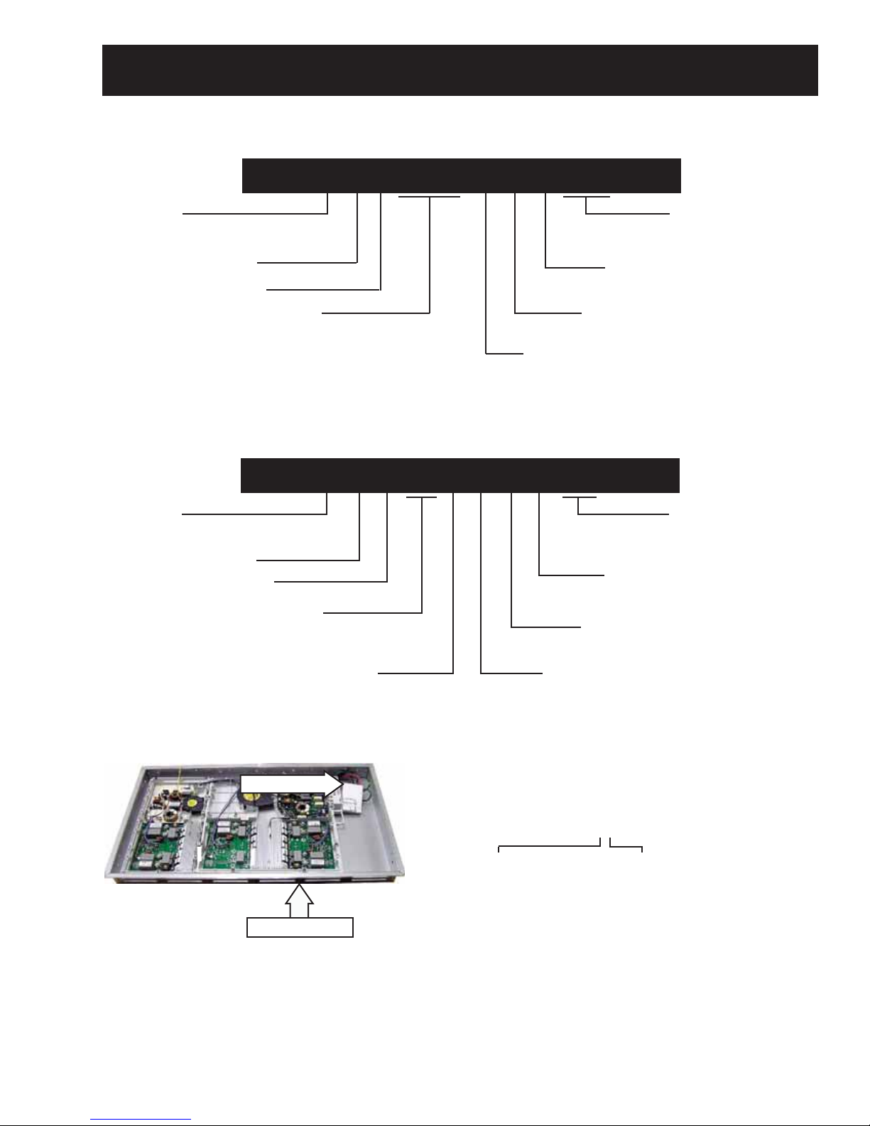
Normal Operation:
When activated by the touch board, a fi lter board
supplies 240 VAC to 1 or 2 generator boards along
with the LINbus (Logic) connections. Each generator
board operates 1 or 2 elements.
The 30-in cooktops have 1 fi lter board that supplies
voltage to 2 generator boards. The left generator
board operates the 2 left-side elements. The right
generator board operates the 2 right-side elements.
Filter Board
The 36-in. cooktops have 2 fi lter boards that supply
voltage to 3 generator boards. The left fi lter board
supplies voltage to the left generator board. The left
generator board operates the 2 left-side elements.
The right fi lter board supplies voltage to the center
and right generator boards. The center generator
board operates the center element and the right
generator board operates the 2 right-side elements.
Right Filter Board
Left Filter Board
Left
Generator
Board
Center
Generator
Board
Right
Generator
Board
Left
Generator
Board
Right
Generator
Board
Generator board maximum output is 3700W. When
using an element on high and a second element
sharing the same generator board is then operated,
the second element will receive priority. For
example, if the fi rst element was using 3700W when
the second element was turned on, power on the
fi rst element will be reduced to a lower setting.
7 "- 2500 W
7 "- 2500 W
7 "- 2500 W
7 "- 2500 W
Element Size and Wattage
30-in. Cooktop
6 "- 1800 W
11 "- 3700 W
36-in. Cooktop
6 "- 1800 W
11 "- 3700 W
8 "- 3200 W
– 16 –
Page 17

Component Locator Views
t
e
u
36-in. Models ZHU36 and PHP960
Glass
Elements
Insulation Left
Left
Generator
Module
Filter
Board
Left
Side
Generator
Board
Left
Generator
Module
Box
Fan Covers
Fan
Center
Generator
Board
Foam Seals
Wire Harness
Wiring
Cable
Harness
Kit
Electrical
Cover
Touch Board
Filter
Board
Conduit
Clamp
Insulation Right
Aluminum
Heat Shield
Righ
Gen
Mod
Right Side
Generator Board
Right Generator Module Box
Protective Tape
Burner Box
Hold-Down
Brackets with
Thumbscrews
Baffle
– 17 –
(Continued next page)
Page 18

30-in. Models ZHU30 and PHP900
Elements
Touch Board
Shield
Glass
Wiring Harness
Cable Kit
Left Side
Generator
Board
Fan
Fan Cover
Foam Seal
Wire Harness
Electrical
Cover
Filter Board
Right Side
Generator
Board
Generator Module
Generator Module Box
Protective Tape
Burner Box
Hold-Down
Brackets with
Thumbscrews
Conduit
Clamp
Baffle
– 18 –
Page 19

36-in. Models ZHU36 and PHP960
Aluminum
Heat Shield
Touch Board
Filter Board
Left Side Generator Board Center Generator Board
Left Side
Fan
Main Fan
Thermal
Cut-out
Filter Board
Thermal
Cut-out
Right Side Generator Board
– 19 –
(Continued next page)
Page 20

30-in. Models ZHU30 and PHP900
Aluminum
Heat Shield
Touch Board
Fan
Filter Board
Thermal
Cut-out
Right Side Generator Board
Left Side Generator Board
– 20 –
Page 21

Cooktop Components
WARNING: Before servicing the cooktop, power
must be removed from the cooktop by turning the
power off at the circuit breaker.
WARNING: Sharp edges may be exposed when
servicing. Use caution to avoid injury. Wear Kevlar
gloves or equivalent protection.
Note: When servicing the cooktop, care must be
taken not to scratch or damage the glass.
All components are accessible by removing the •
glass top.
If the display/touch board is damaged, it can •
be replaced as a unit by removing the glass top
and replacing the touch board. The touch board
is located by pins and springs/foam tape on the
back side of the board.
If the power or fi lter boards are damaged, they •
can be replaced by removing the glass top,
removing the elements, removing the touch
board, and removing the aluminum heat shield
and insulation. This will allow access to the
electronics assemblies, and the board can be
removed and replaced.
Cooktop Removal From Countertop
To remove the cooktop from the countertop:
Caution: The hold-down brackets, heat baffl e (if
installed), and screws on the bottom of the burner
box can damage the countertop surface. Use care
to protect the countertop appearance.
Open the cabinet door and remove each of the 1.
2 thumbscrews that secure the cooktop to the
bottom of the countertop.
Remove the outer hex-head screw from each 2.
hold-down bracket.
Loosen the inner hex-head screw from each 3.
hold-down bracket.
Cooktop Countertop
Cooktop
Bracket
Countertop
Appearance Defects
Scratches, marks, discoloration, stains, spots, etc.
can be caused by food, cookware, utensils, cleaning
solutions, or water. Before replacing the cooktop,
use the cooktop cleaning procedure outlined in the
Owner’s Manual.
Thumbscrew
Inner Screw
Outer Screw
– 21 –
(Continued next page)
Page 22

4. Turn the bracket inwards to avoid interference
when lifting the cooktop from the countertop.
Bottom of Cooktop
Note: In the following step a baffl e is not installed if
cooktop is installed over an oven.
Glass Maintop
The glass maintop must be removed for element,
sensor testing, and touch board replacement. The
glass maintop is attached to the burner box with
twelve 1/4-in hex-head screws (4 on the front, 4 on
the back, and 2 on each side). After removing the
screws, the glass maintop can then be lifted straight
up and placed on a towel or padded surface.
30-in. Model
Elements
5. Remove the two 1/4-in. hex-head screws and
the baffl e from the bottom of the cooktop.
Note: In the following step, it will be necessary to
utilize 2 strips of wood or cardboard.
6. Push upward on the bottom of the burner box
approximately 4 in. and rotate slightly left or
right (to the best working advantage). Shim
under the burner box with protective wood or
cardboard as shown.
Each element consists of a coil and a sensor. The
resistance value of the coil is less than 1Ω at room
temperature. The resistance value of the sensor is
1000Ω at room temp (+or-10%). The sensor has a
positive coeffi cient. As the temperature increases,
the sensor's resistance increases. The sensor and
coil are replaced as a complete assembly.
To remove heating elements:
Remove the glass maintop. (See 1. Glass Maintop.)
Mark the alignment pins and guides for correct 2.
replacement.
Caution: To prevent damage to element insulation,
care should be taken when handling an element.
Note: If some insulation should separate from the
element, it can be placed back on the element in its
original position. Do not use any adhesives.
3. Lift an element off the pins and carefully place it
away from the wire entry.
+
O
N
/O
F
F
-
P
r
o
f
i
l
e
+
O
+
N
/O
F
F
O
N
/O
F
-
F
-
HOT
WA
R
MING ZO
1
2
IN
N
E
9
IN
+
6 IN
O
N
/
O
F
S
F
U
-
R
FA
C
E
C
O
N
T
R
O
L
LOC
+
K
O
N
/
O
F
F
-
Guide
Sensor
Element
Pin
(Continued next page)
– 22 –
Page 23

4. Lift and fold back the insulation from the wire
entry in the heat shield.
Note: On 11- and 8-in. elements, the choke must
be removed and transferred to the replacement
element. The choke must be attached at the same
location on the wires and secured with a plastic wire
tie.
Insulation
5. Note the routing of the element wires and
loosen the two slotted T-25 Torx screws holding
the element wires to the generator board.
Note
The element wire terminals are forked and can •
be removed without completely removing the
screws.
The individual wires from each element have no •
polarity and can be connected to either of the
screw posts for that specifi c element.
6. Use a fl atblade screwdriver to press the lock tab
inward, then lift the element sensor connector
from the generator board.
Choke
Plastic Wire Tie
Touch Board
The touch board employes a capacitive touch
system. When the glass keypad is touched, the
circuit is completed and the touch board responds
to the selection.
The touch board is positioned under the glass top.
Springs attached to the bottom of the touch board
and capacitance foam pads on top, provide precise
touch sensitivity between the touch board and the
cooktop glass.
To remove the touch board:
7. Extract the element wiring from the wire entry in
the heat shield.
Element Connection
Sensor Connection
Element Connection
Remove the glass maintop. (See 1. Glass Maintop.)
Note the location of the touch board wire 2.
harness, then disconnect the wire harness from
the touch board.
Note: To insure proper positioning when replacing
the touch board, be sure to engage pins in guides.
Pin
Capacitance Foam Pad
Guide
– 23 –
(Continued next page)
Page 24

Note: The bottom of the touch board is attached to
the heat shield with an adhesive foam cushion.
3. Raise the back of the touch board
approximately 1 inch. Using a putty knife at a
shallow angle, gently separate the foam spacer
from the heat shield.
Putty Knife
Note: If one or more functions do not work and no
apparent damage is present, the cause can be an
excessive fl at-bottom drop of the packaged unit
during shipping/handling. The force of the drop can
position the heat shield out of proper alignment to
the heat shield mounting tabs. This would cause
improper spacing between the underside of the
glass top and the capacitive switches on the
module, rendering the switches inoperative.
Result of Excessive Flat-bottom Drop
Heat Shield Tab
Note: Make sure all springs and capacitance foam
pads are in place for precise touch sensitivity
between the touch board and the cooktop glass.
Spring
Heat Shield
To correct a misaligned heat shield it is necessary to
remove the glass top. (See Glass Top.)
There are 10 tabs on 30-in. models and 14 tabs
on 36-in. models. All tabs are located along the
perimeter of the heat shield.
Tab Locations- 30-in. Model
– 24 –
(Continued next page)
Page 25

Tab Locations - 36-in. Model
In the following illustrations, the heat shield is out of
alignment due to an excessive fl at-bottom drop of
the cooktop. A large fl at blade screwdriver can be
inserted in the gap on the left-side of the tab.
It may be necessary to insert the screwdriver in the
right-side gap, push down on the screwdriver, and
raise the heat shield even with the tab.
Inspect all tab-to-heat shield alignment areas.
Repeat this alignment procedure on all tabs, if
necessary.
The heat shield can be aligned with the tab by
pushing down on the screwdriver and raising the
heat shield even with the tab.
Properly Aligned Heat Shield
– 25 –
Page 26

Heat Shield
To remove the heat shield:
Remove the elements. (See 1.
6. Remove the 20 Phillips-head screws from the
top of the heat shield. (On 30-in. models, remove
the 5 Phillips-head screws from the top of the
heat shield.)
Elements.)
Lift and remove the left and right insulation 2.
spacers.
Disconnect the touch board wire harness and 3.
remove the tape that holds the harness to the
heat shield.
Lift the insulation from the wire entry in the heat 4.
shield and tuck the touch board wire harness
under the heat shield.
36-in. model shown
Disconnect
Rail
36-in. model shown
7. Raise the rear of the heat shield approximately 3
inches and disconnect the 2 ground wires from
the bottom of the heat shield.
Rear view shown
Insulation Spacers
5. On 36-in. models, remove the fourteen 1/4-in.
hex-head screws, (5 on the front, 5 on the back,
and 2 on each side) from the outside of the
burner box. (On 30-in models, remove the 10
1/4-in. hex-head screws, (3 in the front, 3 in the
back, and 2 on each side) from the outside of
the burner box.)
36-in. model shown
8. Lift and remove the heat shield from the burner
box.
Note
The generator modules are not secured to •
the burner box. With the heat shield removed,
generator modules can be accidentally moved
out of position. To ensure proper alignment of
the modules to the heat shield, it may be helpful
to note and mark the position of the generator
modules.
If a generator module has shifted out of position, •
it may be helpful to drive one corner screw and
then shift the generator module as necessary to
align the other holes.
– 26 –
Page 27

LINbus Connectors
Caution: To prevent damage to LINbus (Local
Interconnect Networkbus) connections, properly
use (as shown below) a Molex 69008-1070 tool when
removing LINbus connectors.
Note: A Molex 69008-1070 tool will be provided with
any part that requires the LINbus connectors to be
removed.
Molex 69008-1070 Tool
Correct way: Use side-to-side motion to remove the
LINbus connector.
CORRECT
Note
LINbus is a communication network comprised •
of a LIN master and one or more LIN slaves. In
these cooktops, the fi lter board (right fi lter board
on 36-in. models), acts as the LIN master while
the generator boards and left fi lter board (on
36-in. models) are the LIN slaves.
Do not use front-to-back motion to remove LINbus
connector.
INCORRECT
All of these components receive a signal to •
perform a specifi c task, but only the appropriate
component will act on the message and
respond accordingly. The component which acts
on the specifi c task is based on programming.
Since the LINbus signal is a digital control signal,
special equipment, such as an oscilloscope, is
required to measure it.
Touch
Board
Generator
Board
Element
Filter
Board
Generator
Board
Element
– 27 –
Page 28

Generator Boards
To remove the generator boards:
Remove the heat shield. (See 1.
Note: The thermal cut-out on the right and left
generator boards on the 30-in. model and on the
center and right generator boards on the 36-in.
models are joined together with 2 metal clips. The
clips must be removed to replace either generator
board.
2. If applicable, use a small fl at blade screwdriver
to pry up and remove the 2 thermal cut-out
clips.
Clip
Heat Shield.)
6. Remove the two T-15 Torx screws that hold the
generator to the module base.
7. Lift the heat sink side and slide the generator
board away from the 2 tabs on the module
base.
Tab
Disconnect
Disconnect
Disconnect
Tab
Thermal
Cut-out
Clip
3. Mark the location of the black L1 and the blue L2
wires and disconnect both from the generator
board.
Note: When replacing the L1 and L2 wiring
connecting the fi lter board to the generator board,
connect that wiring in a matching confi guration. For
example, if the L1 output is connected to the bottom
terminal on the fi lter board, it must be connected to
the bottom terminal on the generator board.
Thermal Cut-out
The thermal cut-out is located between the fi ns of
each generator board heat sink and is connected
to the fi lter board with a wire harness. The location
of the thermal cut-out allows it to sense an overtemperature condition of the generator board.
The thermal cut-out has a resistance value of less
than 1 Ω and opens at approximately 250°F. An
open thermal cut-out will stop operation of the
cooktop. If the thermal cut-out is open, check for
proper operation of the fan and possible vent
obstructions.
Disconnect
4. Disconnect the LINbus connector. (See
Connectors.)
5. Note the position of the thermal cut-out and pull
it out of the heat sink fi ns.
LINbus
Thermal Cut-out
– 28 –
Page 29

Filter Board
To remove the main fi lter board:
5. Mark the location, then disconnect the black L1,
blue L2, and ground wire connections on the
fi lter board.
Remove the heat shield. (See 1.
Heat Shield.)
Lift the front of the module and mark the 2.
location of the black, red, and green wires and
the 2 jumper blades connected to the fi lter
board power terminals.
Using a T-20 Torx or a fl at blade screwdriver, 3.
remove the 4 screws, black and red wires, and
the 2 jumper blades.
Loosen the ground wire screw and remove 4.
the ground wire from the fi lter board power
terminal. Lower the module into the burner box.
LINbus
Remove
Tab
6. Disconnect the thermal cut-out, touch board,
and fan motor wire harnesses.
7. On 36-in. models, disconnect the fi lter-to-fi lter
wire harness.
8. Disconnect the LINbus connectors. (See
Connectors.)
LINbus
9. Using a fl at blade screwdriver, carefully press in
the large 1 (30-in. model) or 2 (36-in model) tabs
away from the fi lter board. Lift the fi lter board
and pull the fi lter board away from the smaller
tab on the module base.
Remove
Jumper
Blade
Remove
Remove
Loosen
Jumper
Blade
Bottom of module shown
Tab
Note
Tab
LINbus
Touch Board
Wire Harness
Filter-to-Filter
Wire Harness
Arrows indicate disconnect locations
To remove the left side fi lter board on the 36-in. model, follow steps 1, and 5 through 9. The touch board •
wire harness is not connected to the left side fi lter board.
The left side fi lter utilizes a non-replaceable fuse. Never attempt to replace the fuse. If the fuse is found to •
be open, replace both left side fi lter and generator boards.
– 29 –
Page 30

Fans
The fan on the 30-in. model cools the left and right
generator board heat sinks.
The 36-in. model utilizes 2 fans. The main fan cools
the right and center generator board heat sinks. An
additional fan cools the left side generator board
heat sink.
Fans change speed based on heat. At low settings
the fan may not operate. As heat increases, the
fan will come on and increase in speed as heat
increases. When the highest power level (Boost)
is selected (indicated by H on the display), the fan
automatically comes on.
A single wire harness is connected to each fan
motor. All fans are operated by 12 VDC motors.
Caution: To prevent damage to fragile fan locking
tabs, test fan before removing it from the module.
Note: When testing these fans:
• You cannot test with an ohmmeter.
30-in. Model Fan and 36-in Model Main Fan
Disconnect
36-in. Model Left Side Fan
Disconnect
• Fan can be run for a short period of time using
a 9-volt battery. Connect the negative (-) battery
terminal to the black wire. Connect the positive (+)
battery terminal to the white wire.
The fan for the 30-in. model and the main fan on the
36-in. model are attached to the module base with 5
tabs. On the 36-in. model the left side generator fan
is attached to the module base with 3 locking tabs.
It is necessary to remove the heat shield to access
the fans. (See Heat Shield.)
– 30 –
Page 31

Diagnostics and Service Information
Failure Codes
The cooktop operates a self-diagnostic mode when power is applied. The touch board has error codes that
can be utilized by the service technician in order to quickly identify failed or improper operation of certain
cooktop components. To access failure codes, simultaneously press the TIMER ON/OFF and CONTROL LOCK
for approximately 10 seconds. Error codes will blink in the window of the corresponding element. The
pads
replacement of the failed component will clear the error code.
Whenever a failure code is encountered and before attempting to replace any components:
Turn off the power supply for 30 seconds, then reset it to see if this clears the failure code.1.
Verify proper voltage and orientation of the power supply wiring connections.2.
FAULT CAUSE CORRECTIVE ACTION
Er31
(36-in. models
only)
Er47 Bad communication in the ribbon
Er39 Internal electronic failure on
Er20 Internal electronic failure on
Er22 Internal electronic failure on
Ec Touch board is perceiving water
Eo Rate of temperature increase is
One fi lter board not confi gured to
work with the other fi lter board.
cable between touch board and
fi lter board.
touch board
touch board
touch board
or food on keypanel.
too fast or temperature at element is too high
Press and hold timer up key.
Press and release RF on/off key.
Press and release LF key.
Release timer up key.
Allow display to scroll horizontal bars and beep.
Replace fi lter board.
Visually check ribbon cable connection from touch
board to fi lter board.
Replace fi lter board.
Replace touch board.
Replace touch board.
Replace touch board.
Clean keypanel area. Replace touch board.
Check if an empty pan is being heated.
Check for obstruction in fan, wire connections to board.
Check fan vents for air blockage. Replace element.
(Continued next page)
– 31 –
Page 32

FAULT CAUSE CORRECTIVE ACTION
E5 Internal electronic failure on fi lter
board
E6 Internal electronic failure on gen-
erator board
E7 Unknown error in system Visually check for loose wires/connections. Replace
E9 Rate of temperature increase is
too fast or open sensor
Element not
Auto shut off activated Refer to Owner’s Manual―unit shuts down
hot enough/
element shuts
down
Foreign object on keypanel area
is activating touch board.
Pan not detected. Check pans for fl at bottom.
Pan not detected. Check pans with magnet for steel content.
Pan not detected. Check pan size vs element size.
Element turns off if pan is off
burner more than 30 seconds.
Element
changes
Internal temperature mainte-
nance
cooking level
Fan not running
Display fl ash-
es,
not heating
Fan doesn’t run at low heat set-
tings.
Pan not detected. Check pans for fl at bottom.
Pan not detected. Check pans with magnet for steel content.
Pan not detected. Check pan size vs element size.
Element not connected, open
connection.
Buzzing sound Elements may make a “buzz”
sound on boost and high.
Check AC coming to home >208 VAC.
Replace fi lter board.
Replace generator board.
generator module.
Visually check sensor connection to generator board.
Replace element.
Replace generator board.
after 18 hours.
Clear obstruction from keypanel.
Check if pan has been removed from element for more
than 30 seconds.
Refer to Owner’s Manual―element reduces from Boost
to 9 after 10 minutes.
Fan changes speeds based on heat.
Check connections on element wires.
Refer to Owner’s Manual― element may make an audible sound when on high.
– 32 –
Page 33

WARNING: To prevent electrical shock, disconnect power to the cooktop prior to servicing.
Model ZHU36 and PHP960
Aluminum Plate
Schematics and Wiring Diagrams
2 Wire
CAUTION: *A special tool
is required when removing
the connections (marked
with an *) from the circuit
boards. Damage to the
circuit boards or cables
may occur without
the special tool.
*
Caution: *A special tool is required
when removing the connections
(marked with an *) from the circuit
boards. (See LINbus Connectors.)
Damage to the circuit boards or wiring
harnesses may occur without utilizing
the special tool.
X3
Not used
X2
Not used
4 Wire
X1
– 33 –
*
*
*
WIRE COLORS
BARE U
BLACK B or BK
BLUE N or BU
BROWN C or BR
GRAY S or GY
GREEN G or GN
ORANGE O
RED R
VIOLET V
WHITE W
YELLOW Y
(Continued Next Page)
Page 34

Model ZHU30 and PHP900
Aluminum Plate
Ground
CAUTION: *A special tool
is required when removing
the connections (marked
with an *) from the circuit
boards. Damage to the
circuit boards or cables
may occur without
the special tool.
*
GND
L1
L2
Caution: *A special tool is required
when removing the connections
(marked with an *) from the circuit
boards. (See LINbus Connectors.)
Damage to the circuit boards or wiring
harnesses may occur without utilizing
the special tool.
– 34 –
Touch Board
Cable
WIRE COLORS
BARE U
BLACK B or BK
BLUE N or BU
BROWN C or BR
GRAY S or GY
GREEN G or GN
ORANGE O
RED R
VIOLET V
WHITE W
YELLOW Y
Page 35

Warranty
All warranty service provided by our Factory Service Centers,
or an authorized Customer Care
®
technician. To schedule
service, on-line, visit us at ge.com, or call 800.GE.CARES
(800.432.2737). (In Canada, call 1.800.561.3344.) Please have
Staple your receipt here.
Proof of the original purchase
date is needed to obtain service
under the warranty.
serial number and model number available when calling for
service.
For The Period Of: GE Will Provide:
One Year Any part of the cooktop which fails due to a defect in materials or workmanship. During this
From the date of the limited one-year warranty, GE will also provide, free of charge, all labor and in-home service
original purchase to replace the defective part.
What GE Will Not Cover:
■ Service trips to your home to teach you how to use
the product.
■ Improper installation, delivery or maintenance.
■ Failure of the product if it is abused, misused,
or used for other than the intended purpose or
used commercially.
■ Damage to the glass cooktop caused by use of
cleaners other than the recommended cleaning
creams and pads.
■ Replacement of house fuses or resetting of circuit
breakers.
■ Damage to the product caused by accident, fire, floods
or acts of God.
■ Incidental or consequential damage caused by possible
defects with this appliance.
■ Damage caused after delivery.
■ Product not accessible to provide required service.
■ Damage to the glass cooktop caused by hardened
spills of sugary materials or melted plastic that
are not cleaned according to the directions in
the Owner’s Manual.
EXCLUSION OF IMPLIED WARRANTIES—Your sole and exclusive remedy is product repair as provided in this Limited
Warranty. Any implied warranties, including the implied warranties of merchantability or fitness for a particular
purpose, are limited to one year or the shortest period allowed by law.
This warranty is extended to the original purchaser and any succeeding owner for products purchased for
home use within the USA. If the product is located in an area where service by a GE Authorized Servicer is not
available, you may be responsible for a trip charge or you may be required to bring the product to an Authorized
GE Service location for service. In Alaska, the warranty excludes the cost of shipping or service calls to your home.
Some states do not allow the exclusion or limitation of incidental or consequential damages. This warranty
gives you specific legal rights, and you may also have other rights which vary from state to state. To know
what your legal rights are, consult your local or state consumer affairs office or your state’s Attorney General.
Warrantor in the USA: General Electric Company. Louisville, KY 40225
Warrantor in Canada: Mabe Canada Inc., Burlington, Ontario
– 35 –
 Loading...