

GE Profile JGP656 Series, Profile JGP6560 Series, Monogram ZGU365 Series, Monogram ZGU3650 Series Technical Service Manual
Page 1
g
GE Consumer Home Services Training
TECHNICAL SERVICE GUIDE
Monogram/Profile
Gas Cooktop
MODEL SERIES:
JGP656
JGP6560
ZGU365
ZGU3650
PUB # 31--9056 08/00
Page 2

!
IMPORTANT SAFETY NOTICE
The information in this service guide is intended for use by
individuals possessing adequate backgrounds of electrical,
electronic, and mechanical experience. Any attempt to repair a
major appliance may result in personal injury and property
damage. The manufacturer or seller cannot be responsible for the
interpretation of this information, nor can it assume any liability in
connection with its use.
WARNING
If the information in this manual is not followed exactly, a fire or
explosion may result causing property damage, personal injury or
death. If you smell gas:
- Do not try to light any appliance.
- Do not touch any electrical switch; do not use any phone in
the building.
- Immediately call the gas supplier from a neighbor’s phone.
Follow the gas supplier’s instructions.
- If you cannot reach the gas supplier, call the fire department.
CAUTION
To avoid personal injury, disconnect power before servicing this product. If electrical power is required for diagnosis or test purposes,
disconnect the power immediately after performing the necessary
checks.
RECONNECT ALL GROUNDING DEVICES
If grounding wires, screws, straps, clips, nuts, or washers used to
complete a path to ground are removed for service, they must be
returned to their original position and properly fastened.
GE Consumer Home Services Training
Technical Service Guide
Copyright © 2000
All rights reserved. This service guide may not be reproduced in whole or in part
in any form without written permission from the General Electric Company.
Page 3

Table of Contents
Table of Contents
Cooktop Features and Controls . . . . . . . . . . . . . . . . . . . . . . . . . . . . . . . . . . . . 2
Downdraft Vent Features and Controls . . . . . . . . . . . . . . . . . . . . . . . . . . . . . . 5
Care and Cleaning . . . . . . . . . . . . . . . . . . . . . . . . . . . . . . . . . . . . . . . . . . . . . . . 6
Installation Requirements . . . . . . . . . . . . . . . . . . . . . . . . . . . . . . . . . . . . . . . . . 9
Cabinet Preparation . . . . . . . . . . . . . . . . . . . . . . . . . . . . . . . . . . . . . . . . . . . . . 11
Downdraft Vent Installation . . . . . . . . . . . . . . . . . . . . . . . . . . . . . . . . . . . . . . . 14
Cooktop Installationx . . . . . . . . . . . . . . . . . . . . . . . . . . . . . . . . . . . . . . . . . . . . 17
Conversion to LP (Propane) Gas . . . . . . . . . . . . . . . . . . . . . . . . . . . . . . . . . . 20
Accessories . . . . . . . . . . . . . . . . . . . . . . . . . . . . . . . . . . . . . . . . . . . . . . . . . . . . 24
Removal and Replacement . . . . . . . . . . . . . . . . . . . . . . . . . . . . . . . . . . . . . . . 26
Schematics and Strip Circuitsx . . . . . . . . . . . . . . . . . . . . . . . . . . . . . . . . . . . . 28
Troubleshooting . . . . . . . . . . . . . . . . . . . . . . . . . . . . . . . . . . . . . . . . . . . . . . . . 29
Parts Lists . . . . . . . . . . . . . . . . . . . . . . . . . . . . . . . . . . . . . . . . . . . . . . . . . . . . . 30
Warranty Information. . . . . . . . . . . . . . . . . . . . . . . . . . . . . . . . . . . . . . . . . . . . . 32
– 1 –
Page 4
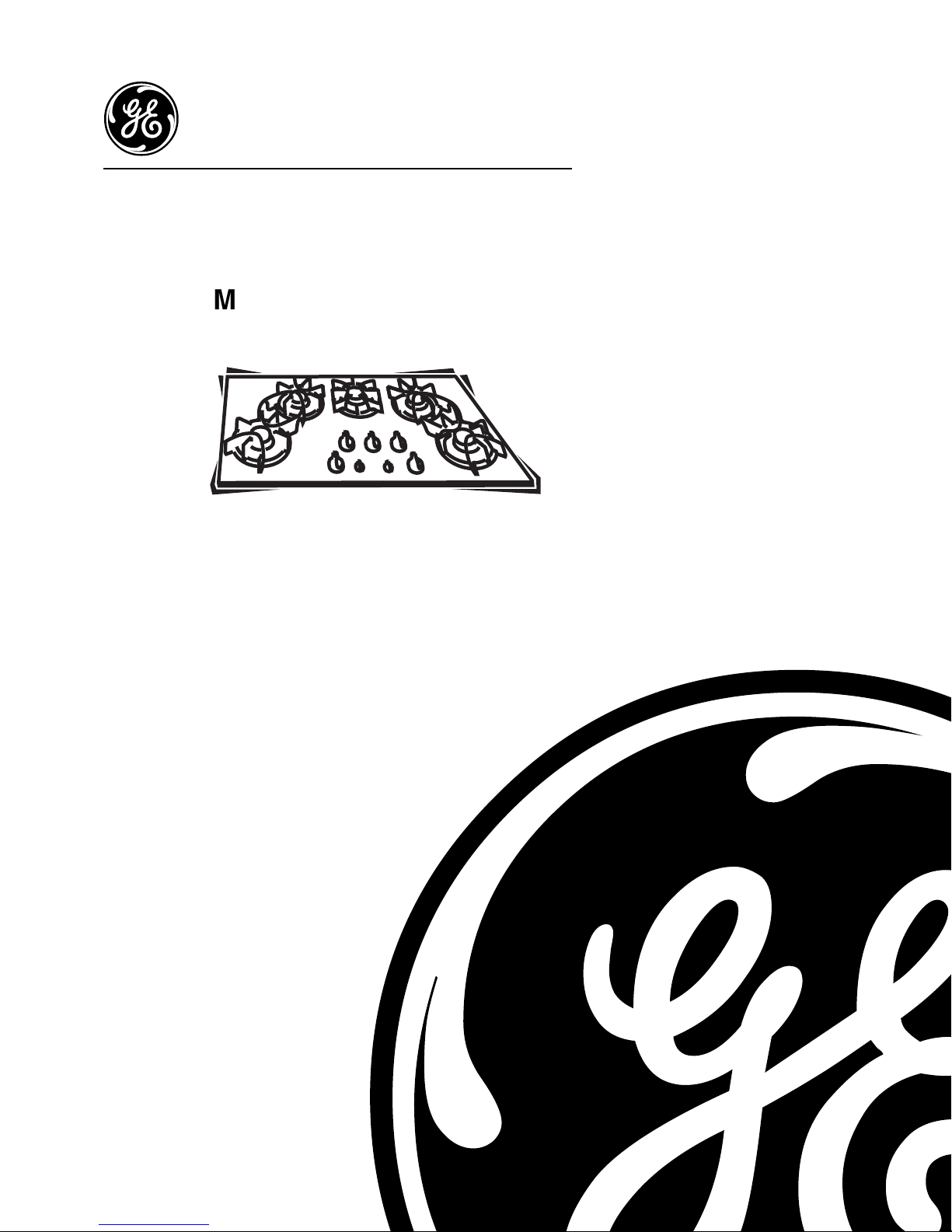
Cooktop Features and Controls
Throughout this manual, features and appearances may vary from the customer’s model.
Feature Index
1. Vent*
2. Vent Filters*
3. Spillproof Burners (2 or 3)
4. Simmer Spillproof Burner
3
5. High-Power Spillproof Burner
6. Fan Speed Control*
7. Vent Control*
8. Surface Unit Controls
9. Glass Cooktop Surface
10. Cast-Iron Burner Grates
*Downdraft models only
3
Using Electric Ignition
The surface burners are lighted by electric
ignition, eliminating the need for standing pilot
lights with constantly burning flames.
All the igniters make clicking sounds and
spark even when only a single burner is being
turned on. Do not touch any of the burners
when the igniters are clicking.
1 2
3
8
6
7988
5
In case of a power outage, the surface burners
on the cooktop can be lit with a match. Hold a
lighted match to the burner, then turn the knob to
the HIGH position. Use extreme caution when
lighting burners this way.
Surface burners in use when an electrical power
failure occurs will continue to operate normally.
4
10
GEA00260
The burners on this cooktop automatically
relight if the flame goes out. All burner igniters
spark while a burner is relighting.
Lighting a Burner
Push the control knob in and turn it
counterclockwise to the desired position from
HIGH to LO.
After the burner ignites, turn the knob in
either direction to adjust the flame size.
To turn a burner off, turn the knob clockwise,
as far as it will go, to the OFF position.
The right rear burner is best for smaller pans
and cooking operations that require carefully
controlled simmering conditions. The center
and two left burners are best for general
Check to be sure the burner you
turned on is the one you want to use.
GEA00261
– 2 –
Page 5
cooking. The front right burner is the high-power
burner for larger pans and fast boiling.
WARNING: Be sure the burners and grates are
cool before you place your hand, a pot holder,
cleaning cloths, or other materials on them.
Caution: Do not operate a burner for an
extended period of time without cookware on the
grate. The finish on the grate may chip without
cookware to absorb the heat.
Selecting Flame Size
Watch the flame, not the knob, as you reduce
the heat.
The flame size on a gas burner should match
the cookware you are using.
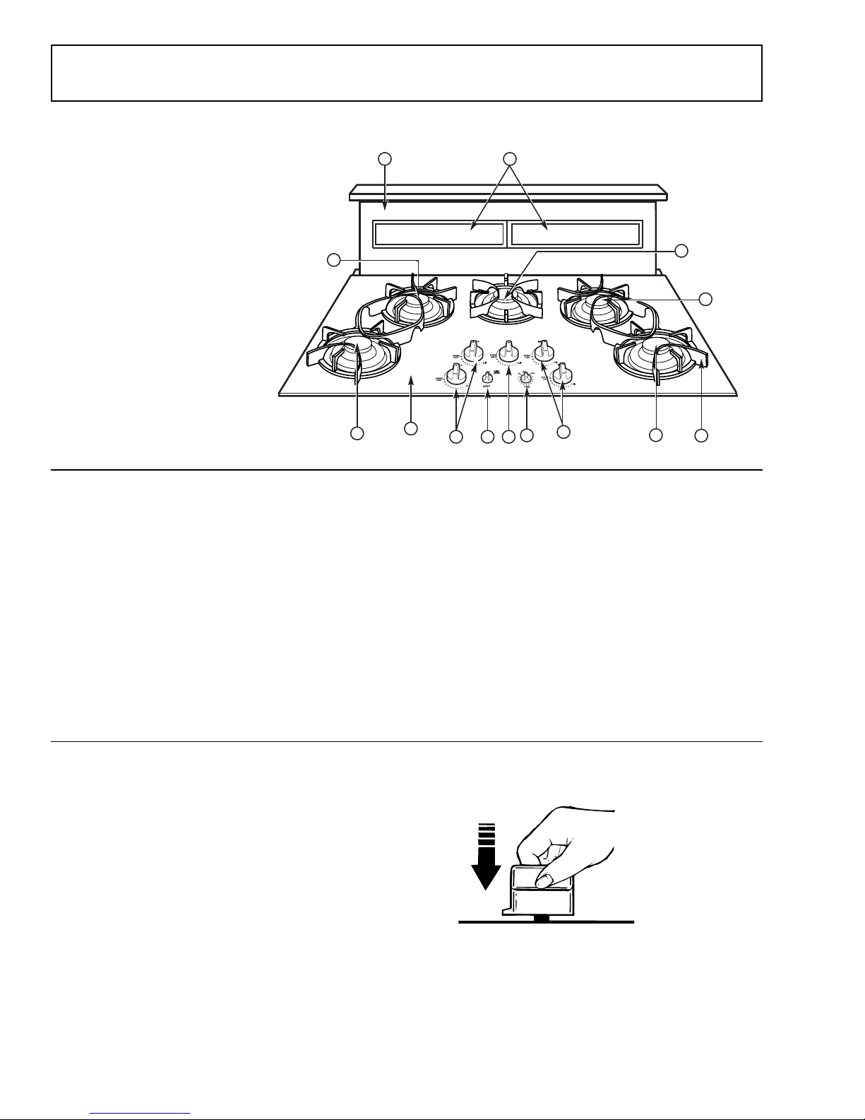
For safe handling of cookware, never let the
flame extend up the sides of the cookware.
Any flame larger than the bottom of the
cookware is wasted and only serves to heat the
handle.
GEA00262
Selecting Cookware
Aluminum: Medium-weight cookware is
recommended because it heats quickly and
evenly. Most foods brown evenly in an aluminum
skillet. Use saucepans with tight-fitting lids for
cooking with minimum amounts of water.
Cast Iron: If heated slowly, most skillets will give
satisfactory results.
Enamelware: Under some conditions, the
enamel of some cookware may melt. Follow
cookware manufacturer’s recommendations for
cooking methods.
Glass: There are two types of glass cookware:
those for oven use only and those for surface
cooking (saucepans, coffee pots, and teapots).
Glass conducts heat very slowly.
Heatproof Glass - Ceramic: This can be used
for either surface or oven cooking. It conducts
heat very slowly and cools very slowly. Check
the cookware manufacturer’s directions to be
sure it can be used on gas cooktops.
Stainless Steel: This metal alone has poor
heating properties, and is usually combined with
copper, aluminum, or other metals for improved
heat distribution. Combination metal skillets
generally work satisfactorily if they are used at
medium heat as the manufacturer recommends.
– 3 –
Page 6
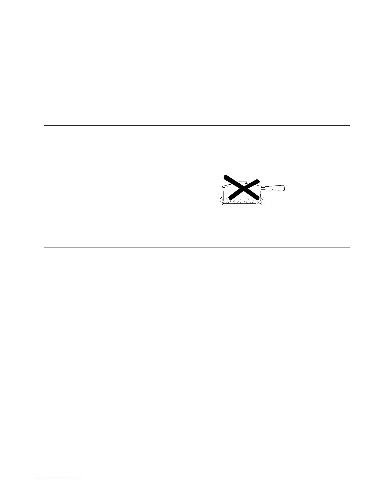
Using Woks
WARNING: Do not use woks that have
support rings. Use of these types of woks, with
or without the ring in place, can be dangerous.
Placing the ring over the burner grate may cause
the burner to work improperly, resulting in carbon
monoxide levels above allowable current
standards. This could be dangerous to the
customer’s health. Do not try to use such woks
without the ring. Serious burns may result if the
wok is tipped over.
We recommend using only a flat-bottomed wok,
available at local retail stores.
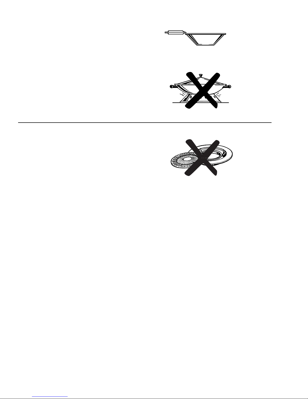
Using Stovetop Grills
WARNING: Do not use stovetop grills on your
sealed gas burners. Using the stovetop grill on
the sealed gas burner will cause incomplete
combustion and can result in exposure to carbon
monoxide levels above allowable current
standards. This can be hazardous to the
customer’s health.
Recommended
Not recommended
GEA00263
GEA00264
– 4 –
Page 7
Downdraft Vent Features and Controls
GEA00265
Throughout this manual, features and appearances may vary from the customer’s model.
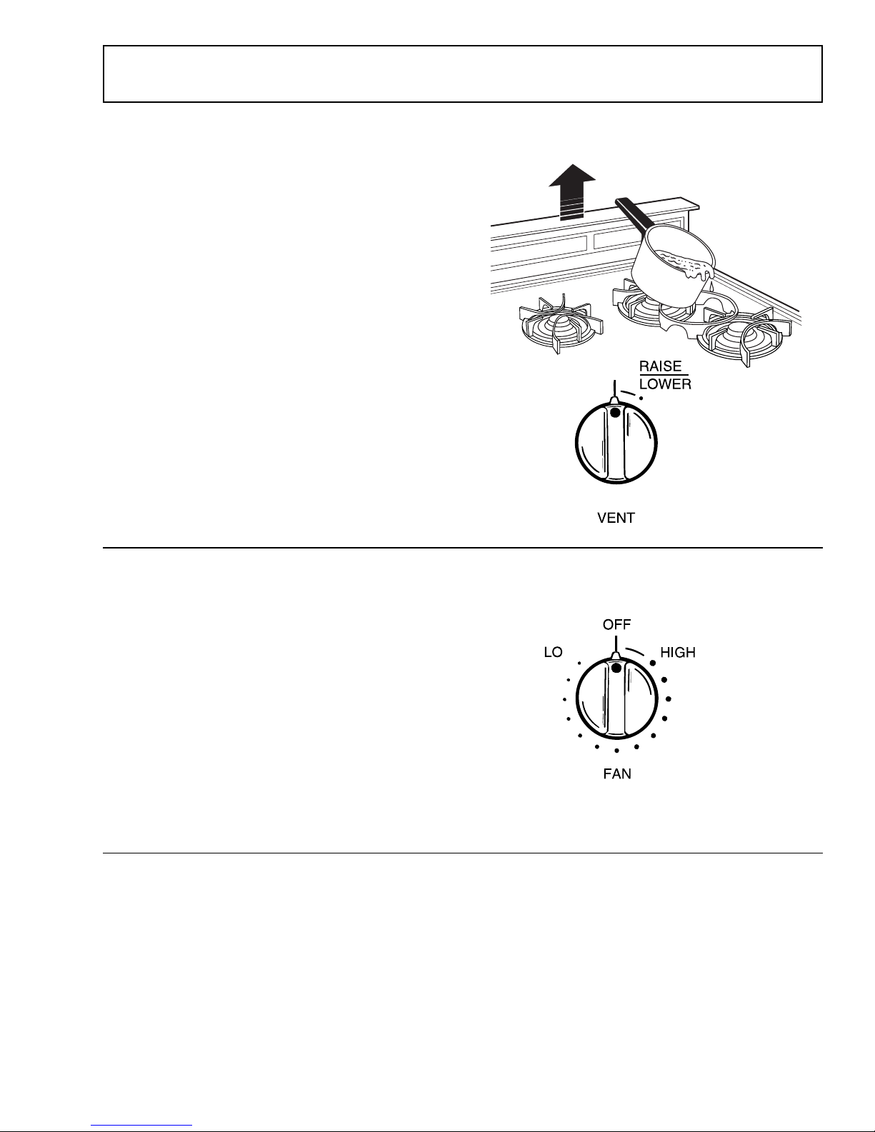
Raising or Lowering the Vent
WARNING: Be careful when raising or lowering the
vent. Be sure pots, pot handles, and other objects
are clear of the vent cover and cannot be struck or
tipped by the vent being raised. Keep hands and
fingers away from all vent parts.
Note: The vent fan will only operate in the fully
extended position.
To raise the vent, turn the VENT knob to the
RAISE/LOWER position. The vent will rise to the
fully extended position. There is no intermediate
position.
To lower the vent, turn the VENT knob again to
the RAISE/LOWER position. The vent will then
descend.
GEA00267
Operating the Vent System
Turn the FAN knob to the HIGH position to turn it
on. If you continue turning the FAN knob, you can
select a fan speed between HIGH and LO.
The FAN knob does not have to be turned to OFF
before the vent is lowered. The fan will
automatically turn off when the VENT LOWER
position is selected.
If the fan was not turned OFF when the vent was
lowered, it will automatically come on at the
previously selected speed when the vent is fully
raised.
GEA00266
– 5 –
Page 8
Care and Cleaning
Proper care and cleaning are important for efficient and
satisfactory service.
WARNING: Before cleaning, be sure all burners are
OFF and disconnect electrical power to the cooktop at
the fuse box, circuit breaker panel, or cooktop power
plug, located inside the cabinets beneath the cooktop.
Cleaning Glass Cooktop
WARNING: Do not cook on, or clean, a broken or
cracked cooktop. Cleaning solutions and spillovers
penetrating the cooktop can create a risk of electric
shock.
Caution: Do not use abrasive materials such as metal
pads, cleansing powder,or scouring pads—they may
scratch the surface. Do not use harsh chemicals such as
bleach or chemical oven cleaners.
GEA00251
GEA00252
To keep the cooktop looking its best, wipe up any spills
as they occur. This will keep them from burning on and
becoming more difficult to remove. As soon as the
cooktop is cool, wash the glass surface with a cloth
moistened with warm, soapy water. Rinse the surface
with clean water, and dry it with a soft cloth. You can use
any liquid household detergent.
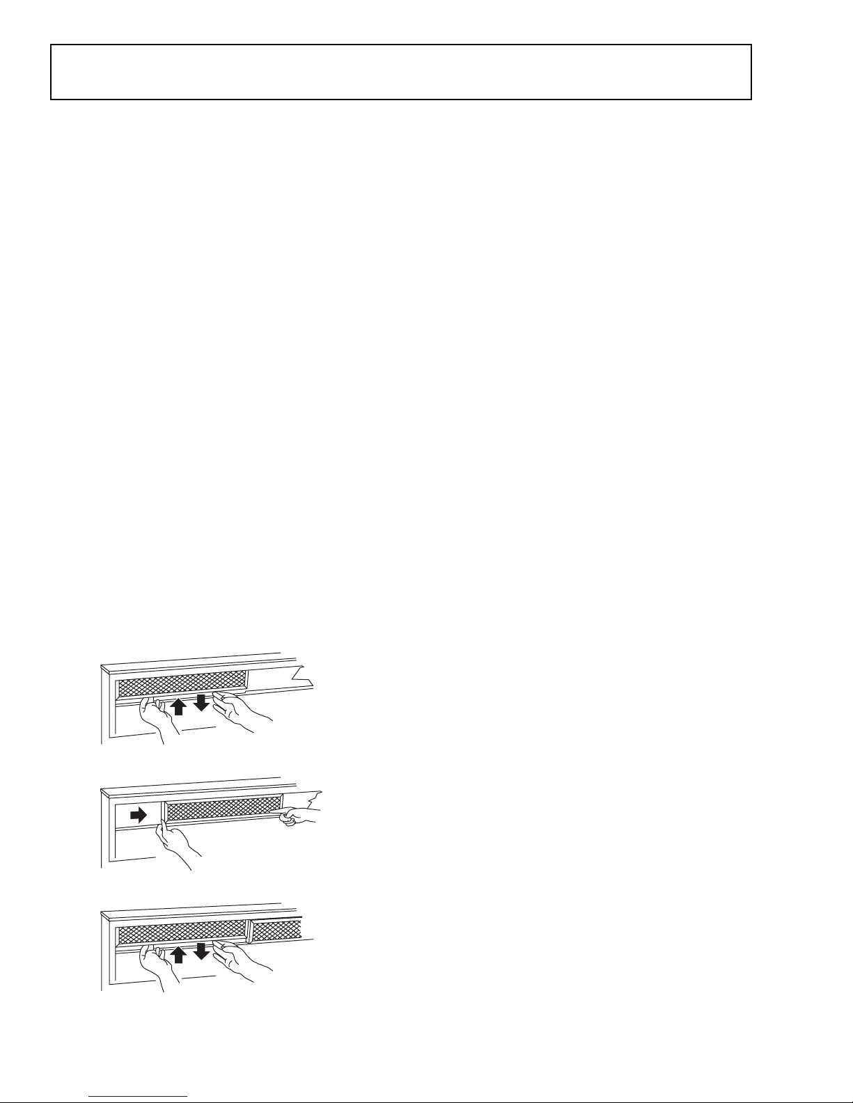
Cleaning Grease Filters
The efficiency of the downdraft depends on a clean filter.
Frequency of cleaning depends on the type of cooking
you do. Grease filters should be cleaned at least once a
month. Never operate the downdraft without the filters in
place.
To remove: Lift up and pull the bottom out. Remove the
left filter first, then slide the right filter to the left and
remove it.
To clean: Soak, then agitate in a hot detergent solution.
Light brushing may be used. Rinse, shake, and remove
moisture before replacing. Filters may be cleaned by
placing them in a dishwasher, although some slight color
fading may occur after several washings.
GEA00253
With careful handling, the filter will last for years. If
replacement becomes necessary, order the part from
your dealer.
– 6 –
Page 9
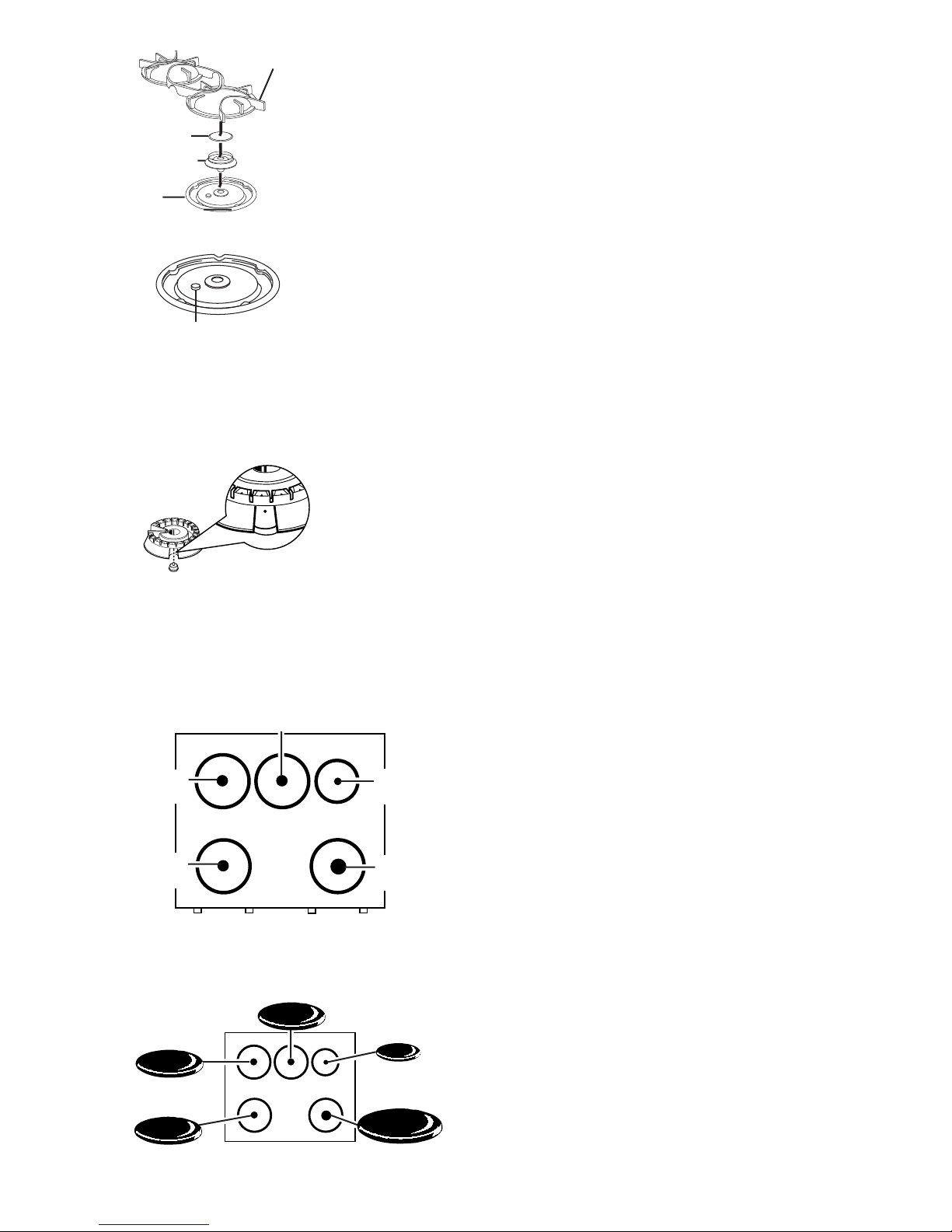
Burner Cap
Burner Head
Burner
Bowl
Burner Grate
GEA00268
Cleaning Control Knobs
To remove a control knob for cleaning, pull it straight
up. Wash the control knobs in soap and water but do not
soak. Avoid getting water into the control knob’s stem
holes.
Cleaning Sealed Burner Assemblies
The electrode of the
spark igniter is
exposed when
the burner head is
Electrode
LITE, all the burners spark. Do not attempt to
disassemble or clean around any burner while
another burner is on. An electric shock may
result, which could cause you to knock over
hot cookware.
Use a sewing needle or twist-tie to
unclog the small hole in the burner
head. After cleaning, make sure the
slot in the burner head is positioned
over the electrode.
Medium Head
(183D5612)
removed. When one
burner is turned to
GEA00270
GEA00269
WARNING: Do not operate the burner without all burner
parts in place.
• Turn all controls OFF before removing burner parts.
The burner grates, caps, and burner heads can be lifted
off, making them easy to clean.
Cleaning Burner Heads
Note: Before removing the burner heads and caps,
remember their sizes and locations. Replace them in the
same locations after cleaning.
For proper ignition, make sure the small hole in the
section that fits over the electrode is kept open. A
sewing needle or wire twist-tie works well to unclog it.
The slits in the burner heads of your cooktop must be
kept clean at all times for an even, unhampered flame.
You should clean the surface burners routinely,
especially after bad spillovers, which could clog these
openings. To remove burned-on food, soak the burner
heads in a solution of mild liquid detergent and hot water
for 20 to 30 minutes. For more stubborn soil, use a
toothbrush.
Medium Head
(183D5612)
Medium Head
(183D5612)
Front of Cooktop
Medium
Cap
Medium
Cap
Medium
Cap
Front of Cooktop
Small Head
(183D5613)
Large Head
(183D5614)
GEA00271
Small
Cap
Large
Cap
GEA00272
Before putting the burner head back, shake out excess
water and then dry it thoroughly by setting it in a warm
oven for 30 minutes. Replace the burner heads and
caps. Make sure the heads and caps are replaced in the
correct locations. There are 2 or 3 medium, 1 large, and
1 small head and cap.
Cleaning Burner Caps
Lift off when cool. Wash burner caps in hot, soapy water
and rinse with clean water. You may scour with a plastic
scouring pad to remove burned-on food particles. Dry
them in a warm oven or with a cloth — don’t reassemble
them wet.
Make sure that caps are replaced on the correct size
burner. There are 2 or 3 medium, one large, and one
small head and cap.
– 7 –
Page 10

GEA00237
Cleaning Burner Grates
Cast-iron burner grates should be washed regularly and,
of course, after spillovers. Wash them in hot, soapy
water and rinse with clean water. Dry the grates with a
cloth—don’t put them back on the cooktop wet. When
replacing the grates, be sure they’re positioned securely
over the burners.
To get rid of burned-on food, place the grates in a
covered container or plastic bag. Add 1/4 cup ammonia
and let them soak for 30 minutes. Wash, rinse well, and
dry.
To prevent rusting, apply a light coat of cooking oil on
the bottom of the grates.
Caution: Do not operate a burner for an extended
period of time without cookware on the grate. The finish
on the grate may chip without cookware to absorb the
heat.
Note: Although they’re durable, the grates will gradually
lose their shine, regardless of the best care you can give
them. This is due to their continual exposure to high
temperatures.
Cleaning Stainless Steel Surfaces
Caution: Do not use a steel wool pad on stainless steel;
it will scratch the surface.
Some models have stainless steel surfaces. Clean with
hot, soapy water. Rinse and dry. If food soil remains, try
a general kitchen cleaner such as Fantastik
Green®, or Formula 409®.
For hard-to-clean soil, use a standard stainless steel
cleaner, such as Bon-Ami
®
or Cameo®. Soils can be
soaked for several hours with wet towels. Apply cleaner
with a damp sponge, rinse thoroughly, and dry. Always
scrub lightly in the direction of the grain.
After cleaning, use a stainless steel polish such as
Stainless Steel Magic
®
, Revere Copper and Stainless
Steel Cleaner®, or Wenol All Purpose Metal Polish®.
Follow the product instructions for cleaning the stainless
steel surface.
®
, Simple
– 8 –
Page 11
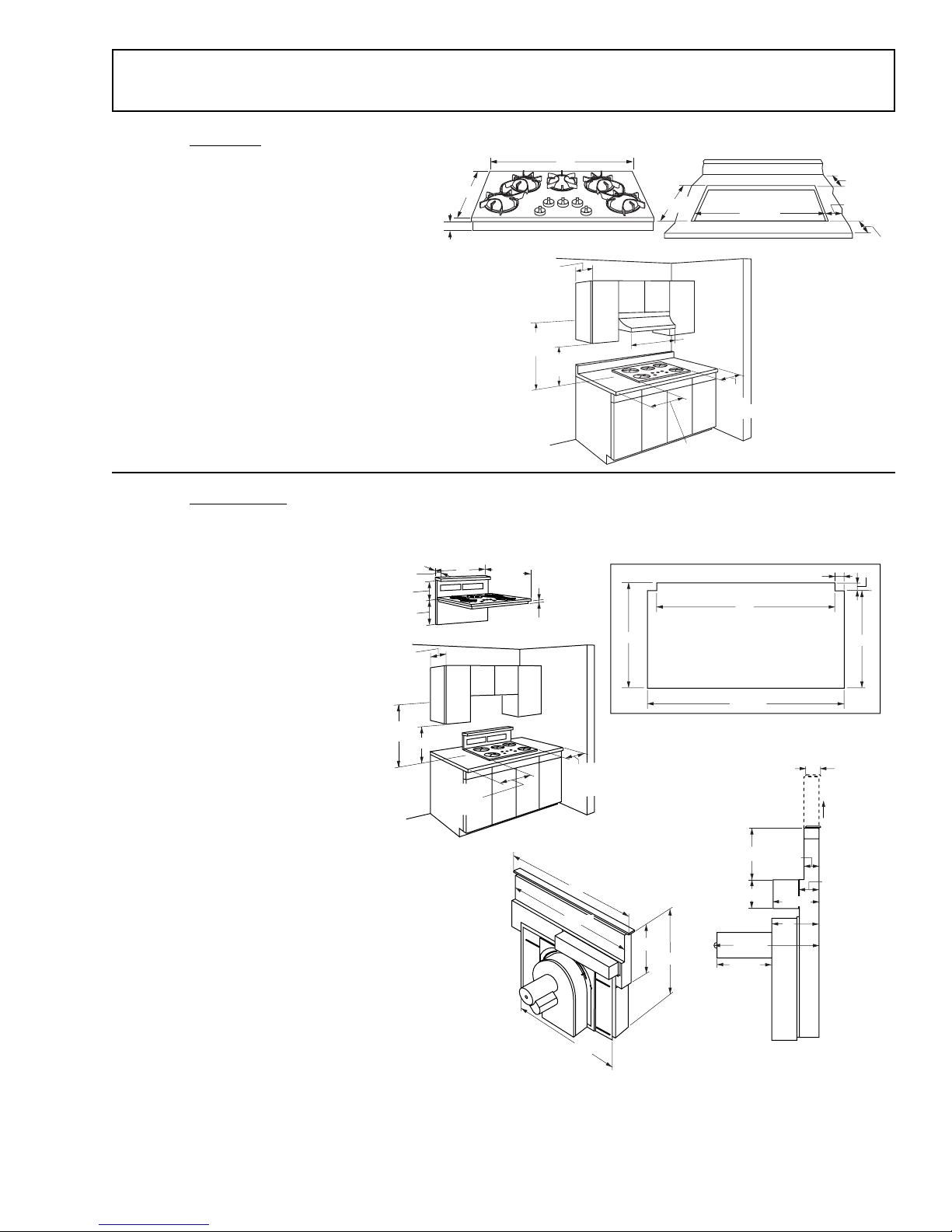
Installation Requirements
36" Gas Updraft Cooktop - Models ZGU3650 and JGP6560
These gas updraft cooktops are only 3"
deep and can be installed over cabinet
drawers.
19-3/4"
36"
18-5/16"
34-7/16"
2-5/16"
8-13/16"
These models are shipped for natural gas
operation. They can be converted to liquid
propane use. (Order ZXLP56 conversion kit.)
3"
13"
Max.
Use these gas updraft cooktops with any 36”
or wider exhaust hood, if desired. No special
ventilation is required.
30"
Min.
18"
Min.
36" Gas Downdraft Cooktop - Models ZGU365 and JGP656
These downdraft systems with a blower,
a motor, and ductwork will occupy
18"Min.
8" Min. to
Wall When
Installed
36"
22-1/4"
2"
8" Min. to
Wall When
Installed
36"
33-3/4"
the cabinet below the cooktop.
Drawers cannot be installed
below this cooktop.
These models are shipped for
natural gas operation. They can
be converted to liquid propane.
(Order ZXLP56 conversion kit.)
These gas downdraft cooktops
are equipped with a vent system
which can be retracted when
not in use.
Note: JXBA56WW (white) or
JXBA56BB (black) blower/motor
assembly is required for both models.
Be sure to order the color that
matches the cooktop.
Accessories (see
Accessories
)
8-3/4"
15"
13"
Max.
30"
Min.
2"
21"
14-3/4"
36" Min.
8" Min. to Wall
27"
8"
Min.
to Wall
Back of Countertop
5/16"
34"
34-5/8"
Front of Countertop
7-1/2"
2-1/4"
3-1/4"
6-3/8"
7"
12-3/8"
5-3/8"
2-1/4"
GEA00274
2"
19"
2"
8-1/2" Lift
3-1/4"
• JXRB57 optional accessory for indoor
remote location of blower/motor assembly.
Use kit when the blower and motor
assembly will be located outside of or below
the cabinet floor.
• JXBC57 optional outdoor cover accessory
may be ordered for installation of blower and
motor assembly on outside wall.
26"
GEA00276
– 9 –
Page 12

Before You Begin
Important Safety Instructions
Read these instructions completely and carefully.
Note: Save instructions for local inspector’s use.
• Observe all governing codes and ordinances.
• This appliance must be properly grounded.
Tools and Materials You will Need:
• Saw
• Large, flat-blade screwdriver
• Duct tape (downdraft only)
• Measuring tape or scale
• Carpenter’s square
• Pipe wrench
• Manual gas line shutoff valve
• Pipe joint sealant that resists action of LP gas
• Duct work to suit the situation (downdraft only)
• Wood screws (downdraft only)
For Flexible Connection Where
Local Codes Permit:
• Flexible metal tubing (same 3/4-in. or 1/2-in.
I.D. as gas supply line)
• Flare union adapter for connection to supply
line (3/4-in. NPT x 3/4-in. I.D. or 1/2-in. NPT x
1/2-in. I.D.)
• Flare union adapter for connection to regulator
(1/2-in. NPT x 3/4-in. I.D. or 1/2-in. I.D.)
For Rigid Connection:
• Pipe fittings as required
These cooktops have been design-certified by the
American Gas Association. As with any appliance
using gas and generating heat, there are certain
safety precautions that must be followed.
The cooktop must be electrically grounded in
accordance with local codes, or in their absence,
with National Electrical Code ANSI/NFPA No. 70 –
Latest Edition.
Installation of cooktop must conform with local
codes, or in their absence, with National Fuel Gas
Code ANSI Z223.1 – Latest Edition.
Disconnect the electrical supply before servicing.
Wall coverings, countertops, and cabinets should
be able to withstand 200 °F heat generated by the
cooktop.
Avoid placing cabinets above the cooktop.
If cabinets are placed above the cooktop, use
cabinets no more than 13 in. deep.
If cabinets are placed above the cooktop, allow a
minimum clearance of 30 in. between the cooking
surface and the bottom(s) of unprotected
cabinet(s).
If a 30-in. clearance between cooking surface and
overhead combustible material or metal cabinets
cannot be maintained, protect the underside of
cabinets above cooktop with insulating millboard
at least 1/4-in. or gypsum board at least 3/16-in.
thick, covered with 28 gauge sheet steel or 0.020
in. thick copper.
Clearance between the cooking surface and
protected cabinets must never be less than 24 in.
Exception:
or cooking appliance over the cooktop shall
conform to the installation instructions packed with
the appliance.
Installation of a listed microwave oven
Vertical distance from the plane of the cooking
surface to the bottom of adjacent overhead
cabinets extending closer than 1 in. to the plane of
the cooktop sides must not be less than 18 in.
Adjacent cabinets should be at least 8 in. from the
side of the cooktop.
– 10 –
Page 13

Cabinet Preparation
Cut Opening for Updraft Cooktop
8-13/16" Min.
to Side Wall
8-13/16"
Min.
Cutout
To Side
Wall
18-5/16"
4-7/16"
Min.
2-1/4"
Min. From
Front of
Countertop
Caution: Wall coverings, countertops, and
cabinets should be able to withstand 200°F heat
generated by the cooktop.
Measure carefully when cutting the countertop.
Make sure the sides of the opening are parallel,
and the rear and front cuts are exactly
perpendicular to the sides.
The gas updraft cooktop is designed to fit in a
36 in. or larger base cabinet. The countertop
cutout for the cooktop must:
• Be 34-7/16 in. wide.
• Be 18-5/16 in. deep.
• Allow at least 4-7/16 in. clearance between the
back of the cutout and the wall.
34-7/16"
GEA00295
• Allow at least 8-13/16 in. clearance from the
right and left sides of the cutout to the adjacent
wall.
• Allow at least 2-1/4 in. clearance between the
front of the cutout and front edge of the
countertop.
The cooktop requires a 3 in. free space below the
countertop. If installing the cooktop above a
cabinet with drawers, it may be necessary to use a
shorter length drawer to allow clearance for the
gas connection. In some cases, two 3/8-in. I.D. 45°
elbows and a pipe nipple may be added between
the regulator and the cooktop to move the
regulator further back in order to avoid
interference with the drawer.
– 11 –
Page 14

Cut Opening for Downdraft Cooktop
1-1/4"
min.
21"
8-3/4"
15"
2"
2-1/4"
min. to
front edge
36"
34"
22-1/4"
2"
19"
34-5/8"
8-13/16"
min. to
side walls
2"
5/16"
GEA00277
Caution: Wall coverings, countertops, and
cabinets should be able to withstand 200°F heat
generated by the cooktop.
Cut out the opening as shown in plan view
diagram (page 9). Measure carefully when cutting
the countertop. Make sure the sides of the
opening are parallel, and the front and rear cuts
are exactly perpendicular to the sides.
The front of the opening must clear the front
support rail on the cabinet, and the rear of the
opening must clear the rear support of the
cabinet.
Measure carefully when cutting the countertop.
Make sure the sides of the opening are parallel,
and the rear and front cuts are exactly
perpendicular to the sides.
The gas downdraft cooktop is designed to fit in a
36-in. or larger base cabinet.
The Countertop Cutout for the Cooktop must be:
• 34-5/8 in. at the front of the counter and 34 in.
at the back.
• 19 in. front to back of notch.
• 21 in. front to back of cutout.
The Notches at the Back of the Cutout are:
• 2 in. forward and 5/16 in. to the inside.
Follow the Illustration Shown:
• Allow at least 1-1/4 in. clearance between the
back of the cutout and the wall.
• Allow at least 8-13/16 in. clearance from the
right and left sides of the cutout to the
adjacent wall.
• Allow at least 2-1/4 in. clearance between the
front of the cutout and the front edge of the
countertop.
– 12 –
Page 15

Power Supply Locations
Gas Supply
Electrical Supply
WARNING: For personel safety, appliance must
be properly grounded.
These cooktops feature pilotless electric ignition
for energy savings and reliability. They operate on
a 120-volt, 60-Hz power supply. A separate circuit,
protected by a 15-amp time delay fuse or circuit
breaker, is required. A properly grounded
three-prong receptacle must be located within
reach of the cooktop’s 4-ft power cord.
The appliance power cord is equipped with a
three-prong (grounding) plug which mates with a
standard three-prong grounding wall receptacle to
minimize the possibility of electric shock hazard.
The customer should have the wall receptacle and
circuit checked by a qualified electrician to make
sure the receptacle is properly grounded and has
correct polarity.
Note: Where a standard two-prong wall receptacle
is encountered, it is the customer’s responsibility
and obligation to have it replaced with a properly
grounded three-prong wall receptacle.
Do not, under any circumstances, cut or remove
the third (ground) prong from the power cord.
Do not use an extension cord.
These cooktops are designed to operate on
natural gas at 4 in. of water column pressure, or
on LP gas at 10 in. of water column pressure.
Cooktops are shipped from the factory set for
natural gas. To use the cooktop with LP gas,
conversion adjustments must be made. (Order
JXLP56 Conversion Kit.)
The pressure regulator must be connected in
series with the cooktop manifold and must remain
in series with the supply line, regardless of the
type of gas being used.
For proper operation, maximum inlet pressure to
the regulator must be no more than 10 in. water
column pressure for natural gas and 14 in. water
column pressure for LP gas.
When checking the regulator, the inlet pressure
must be at least 1 in. greater than the regulator’s
output setting. If the regulator is set for 4 in. of
water column pressure, the inlet pressure must be
at least 5 in. If the regulator is set for 10 in. of
water column pressure, inlet pressure must be at
least 11 in.
Note: Purchase new flexible line. Do not use old,
previously used flexible line.
For ease of installation, and if local codes permit,
the gas supply line into the cooktop should be
1/2-in. or 3/4-in. ID flexible metal appliance
connector, 3 to 5 feet long.
2" Min. Below
Bottom of Counter
5/8"
Forward
of Back
of Cutout
1-5/8"
From Right
of Cutout
GEA00275
Make the gas connection through the rear wall, or
on the cabinet floor at the rear, as illustrated.
Downdraft CooktopUpdraft Cooktop
Do Not Locate Gas or Electrical
Connections Within Shaded Area
34"
29-1/2"
Electrical
Outlet
12" Above
Cabinet Floor
GEA00241
Gas Location
4"
14"
– 13 –
Page 16

Loosen screws to adjust
blower left to right
Downdraft Vent Installation
Venting Options
The downdraft vent is shipped with the discharge outlet
pointing straight down. The outlet can be changed to leftor right-side discharge.
Side-to-Side Adjustments
The blower mounting plate can be adjusted 3-1/2 in. to
the left or right. This will help to align vent discharge to
house ductwork.
Nut location inside the
blower discharge
30 rotation left or right
Discharge down (as supplied)
30° Rotation
For even more flexibility, the entire blower can be rotated
up to 30° left or 30° right.
Discharge Direction
Note: A left or right 90° direction adjustment should be
performed before dropping into countertop opening.
The blower assembly may be removed and turned 90°
for a left- or right-side discharge (see illustration).
1. Flatten the shipping box to use as a pad.
2. Lay the vent on its back onto the pad.
3. Remove 4 nuts holding the blower to the mounting
plate (see illustration). One nut is just inside the
blower discharge.
4. Remove and turn the blower 90° to the right or left.
5. Reinstall 4 nuts.
Cut Holes for Ductwork
Discharge right
Discharge left
GEA00238
1. Temporarily place the vent into the countertop
opening.
2. Push the vent all the way to the back of the opening.
3. If you are transitioning to 6 in. round, place the
transition piece over the discharge outlet.
a. Mark the location and remove the assembly.
b. Cut holes and install the ductwork connections.
Note: For installation of the blower and motor below the
floor, order Kit JXRB57. See
Accessories
.
• For installation of the blower and motor outdoors,
order Kit JXBC57. See
Accessories
.
– 14 –
Page 17

Duct Fittings
Table of Equivalent Lengths
Note: Any home ventilation system, such as
a cooktop with a downdraft exhaust
mechanism, may interrupt the proper flow of
combustion air and exhaust required by
fireplaces, gas furnaces, gas water heaters,
and other naturally vented systems. To
minimize the chance of interruption of such
naturally vented systems, follow the heating
equipment manufacturer’s guidelines and
safety standards such as those published by
NFPA and ASHRAE.
Use the chart at the right to compute the
maximum permissible lengths for duct runs
to outdoors.
Note: Do not exceed maximum permissible
equivalent lengths.
Flexible ducting
WARNING: Do not use flexible plastic
ducting.
If flexible metal ducting is used, all the
equivalent length values entered on the
worksheet for flexible ducting should be
doubled. The flexible metal duct should be
straight and smooth, and extended as much
as possible.
Vent installation should not exceed 150 feet
equivalent length.
Duct Pieces Length* Used Length
6" round, (per foot
straight length) feet
1
3
4
" x 10" (per foot
straight length) feet
6", 90
elbow
6", 45
elbow
1
3
4
" x 10"
90 elbow
1
3
4
" x 10"
45 elbow
1
3
4
" x 10"
90 flat elbow
6" round
1
4
" x 10"
to 3
transition
1
3
4
" x 10"
to 6" round
transition
6" round
1
to 3
4
" x 10"
transition
90 elbow
1
3
4
" x 10"
to 6" round
transition
90 elbow
Equivalent Number Equivalent
1 ft.
1 ft.
15 ft.
9 ft.
16 ft.
5 ft.
18 ft.
7 ft.
5 ft.
20 ft.
12 ft.
Total
– 15 –
6 " round wall
cap with damper
1
3
4
" x 10" wall
cap with damper
6" round
roof cap
6" round
roof vent
Total duct run should not exceed 150 ft.
21 ft.
27 ft.
20 ft.
24 ft.
GEA00240
Page 18

Install Downdraft Vent
1. Remove plastic ties on both ends at top of vent.
Optional Method —
Secure to Cabinet
Side With Top
Screw on Case
Or Use 2nd Screw
Secure the Lower Brackets
to Blower Housing
Plastic Ties
GEA00278
Preferred Method —
Secure the Upper
Brackets With Screws
Located on the Side of
Case and Attach to
Back Wall of Cabinet
GEA00242
2. Place downdraft vent into countertop cutout against
back side.
3. Secure downdraft to countertop with supplied
brackets (see illustration).
• Fasten brackets to top screws on front side of
vent and secure to cabinet side wall just below
countertop,
or
• Fasten one bracket to vent’s side and secure to
cabinet’s back wall.
4. Install two brackets on bottom of vent.
5. Attach brackets to slide screws on vent and to floor
using wood screws (not supplied).
6. When installing in a tile countertop surface, it may be
necessary to apply a locally approved caulking to
cover any gaps.
Install the Ductwork
Use minimum 26-gauge galvanized or 24-gauge
aluminum duct in 6-in. round or 3-1/4-in. x 10-in. size, or
a combination of both. PVC duct should be used if
installing under a poured concrete slab. Do not use
flexible plastic ducting.
Always use an appropriate roof or wall cap with damper.
Laundry type wall caps should never be used.
Air Flow
Duct Tape Over Seam
and Screw
Screw
GEA00205
Use the straightest duct run possible.
For satisfactory performance, the duct run should not
exceed 150 ft. or its equivalent length if bends or other
various fittings are used. Refer to
Lengths
for various duct configurations.
Table of Equivalent
Install ductwork so the piece of duct nearest the
downdraft unit slots into the next piece of duct. Secure
joints with self-tapping screws and apply duct tape
around joints to ensure airtight seal.
– 16 –
Page 19

Cooktop Installation
Regulator
Solid piping or flexible
connector
Pipe stub
Shut-off
valve
GEA00243
1/16"
3/8"
GEA00245
Install the Pressure Regulator
Note: Instead of using solid piping to connect to
the pressure regulator, an approved flexible metal
appliance connector may be used between shutoff valve and pressure regulator, if local codes
permit. Appropriate flare nuts and adapters are
required at each end of the flexible connector.
Install supplied pressure regulator and nipple in
gas line as close to cooktop’s inlet as possible.
Allowances for ventilation ducting may be
necessary. Make sure the regulator is installed in
the right direction.
Install manual shut-off valve in gas line in an easily
accessible location.
WARNING: Do not use a flame to check for gas
leaks.
Turn ON gas. Check for leaks using liquid leak
detector at all joints in system. (Pressure test
nipple is adjacent to gas inlet pipe on rear
right-hand side of cooktop’s bottom.)
Install the Cooktop
Note: If the cooktop is installed into a 36-in. base
cabinet, the pressure regulator must be installed
to the bottom of the cooktop before the cooktop is
placed into the cabinet.
1. Remove packaging from cooktop.
Note: When using test pressures greater than
1/2 psig to pressure-test the gas supply system of
a residence, disconnect cooktop and individual
shut-off valve from gas supply piping. When using
test pressures of 1/2 psig or less to test the gas
supply system, simply isolate cooktop from gas
supply system by closing individual shut-off valve.
Check edges all the way around to be sure all
cutout edges are concealed and there are no
gaps.
3. Carefully lift and remove cooktop.
2. To ensure a good fit, position cooktop over cut-
out opening and carefully lower into place.
GEA00244
4. Cut a 3/16-in. gasket strip in half. Peel off
backing and apply to underside of glass
cooktop edge, on each side at least 3/8 in.
from the back and as close to the edge as
possible without protruding.
– 17 –
Page 20

5. Apply the other gasket strip to underside of
glass at front of cooktop.
6. Remove remaining adhesive backing.
7. Position cooktop over opening, making sure
that power cord is dropped into cabinet.
Electrical Connections of Downdraft
8. Lower cooktop into cutout, pressing gently and
evenly to seat.
Note: If cooktop is installed in a 36-in. base
cabinet, mounting brackets cannot be used
because of interference with cabinet sides. In this
case, cooktop can be secured to cabinet with
angle brackets (not supplied).
Gasket
Countertop
GEA00246
GEA00247
1. Connect three-pin plastic plug from blower/
motor assembly to three-pin plastic socket on
underside of vent, next to conduit.
2. Slide metal cover over connection and secure
with screws.
Service
plate
Electrical
supply cord
6-pin plug
Metal
cover
Electrical
6-pin socket
Pressure
regulator
GEA00248
9. Remove one screw at bottom of cooktop body
on both sides and secure bracket with those
screws. Then secure brackets to cabinet sides.
10. Insert hold-down bracket into highest slots on
right and left sides of cooktop. Cooktop has
three slots; the highest available will depend
on thickness of countertop.
11. Secure brackets to underside of countertop
with screws provided.
3. Connect six-pin plastic plug from downdraft
assembly to six-pin plastic socket on
underside of cooktop, next to power cord.
4. Slide metal cover over connection and secure
with screws.
Connect Power
Plug power cord into properly grounded
receptacle.
– 18 –
Page 21

Assemble Burners and Check Ignition
Assemble burner as shown.
Burner Grate
Burner Cap
Burner Head
Install Filters, Check Operation
of Downdraft
1. To raise vent, turn VENT knob to RAISE/
LOWER. Hold knob until vent begins to rise.
Vent will automatically stop when it is fully
extended.
GEA00251
Burner Bowl
GEA00249
Place burner heads and caps on burners. Make
sure that heads and caps are placed on correct
size burner. There are 1 small, 2 (or 3) medium,
and 1 large head and cap.
Medium Head
(183D5612)
and Cap
Medium Head
(183D5612)
and Cap
Front of Cooktop
Small Head
(183D5613)
and Cap
Large Head
(183D5614)
and Cap
Make sure the slot in the burner
head is positioned over the
electrode.
GEA00250
Check for Proper Ignition
Note: First test may require some time, while air is
flushed out of gas line.
1. Push in one control knob and turn 90° to HIGH
position.
2. Tip filter into opening and pull straight down so
filter rests on slides.
GEA00252
3. Slide filter to right side.
GEA00253
4. Tip other filter into opening and pull straight
down.
5. To turn fan ON, turn FAN knob to HIGH.
Continue turning FAN knob to select a fan
speed between HIGH and LO.
Note: It is not necessary to turn fan OFF before
lowering vent. Fan will automatically turn OFF
when vent is lowered. When fan is not turned OFF
before lowering vent, it will automatically come ON
at previously selected speed when vent is fully
raised.
6. To lower vent, turn VENT knob to RAISE/
LOWER. Hold knob until vent begins to lower.
2. Igniter will spark and burner will light; igniter
will cease sparking when burner is lit.
3. Turn knob to OFF.
4. Repeat procedure for each burner.
– 19 –
Page 22

Conversion to LP (Propane) Gas
WARNING: If you are using LP (propane) gas, all
adjustments described in the following steps must
be made before attempting burner adjustments or
using cooktop.
• Use only approved pipe dope resistant to LP
gas.
Note: The cooktop leaves the factory set for use
with natural gas. If you convert to LP gas, keep
instructions and orifices to convert back to natural
gas.
Parts
The kit should contain the following:
• 1 Orifice—Large size—104-WB28K0093
• 3 Orifices—Medium size—(number to come)
• 1 Orifice—Small size—82-WB28K0094
• 1 Maxitrol LP adapter—WB01K055
• 1 Tie-on card/label for regulator
If you do not have all above-listed components,
contact the nearest GE Service and Parts Center.
Total input rating after conversion:
• Four-burner cooktop 35,000 Btu/hr.
• Five-burner cooktop 44,500 Btu/hr.
Tools Required:
• Adjustable wrench
• Nut driver: 9/32 in. or 7 mm
Convert the Surface Knobs
Valve
Shaft
GEA00254
1. Remove knobs from valve shafts.
2. Fully screw down brass low-flame adjustment
screws into valve bodies with clockwise
rotation.
3. Replace knobs and cams.
Convert the Surface Burners
Burner Grate
Burner Cap
Burner Head
Burner Bowl
GEA00255
Prepare Cooktop for Conversion
1. Turn OFF gas supply at shut-off valve.
2. Turn OFF electrical power to cooktop.
1. Remove grates and burner caps.
Note: Each orifice has a number and letter “L”
indicating LP gas.
• There will be one extra medium orifice spud and
burner head when converting a four-burner
cooktop.
GEA00256
2. Using a 9/32-in. or 7-mm nut driver, remove
and replace brass orifice spud inside each
– 20 –
Page 23

Five-Burner Cooktop Models
5 Burner Cooktop Models
Location BTUs Orifice Size Burner Head
LF, LR 9,500 .89Lmm (II) 183D5612
CTR 9,500 .89Lmm (II) 183D5612
RR 5,000 .63Lmm (I) 183D5613
RF 11,000 .99Lmm (III) 183D5614
Install orifices and position burner caps as shown
89
Medium
Four-Burner Cooktop Models
4 Burner Cooktop Models
Location BTUs Orifice Size Burner Head
LF, LR 9,500 .89Lmm (II) 183D5612
RR 5,000 .63Lmm (I) 183D5613
RF 11,000 .99Lmm (III) 183D5614
89
Medium
63
Small
89
Medium
89
Medium
Front
63
Small
99
Large
GEA00279
burner chimney as shown by number on the
above chart:
3. Place LP gas burner head onto chimney, as
indicated by number.
4. Place correct size burner caps onto burners,
then replace grates.
Convert the Pressure Regulator
WARNING: Do not remove pressure regulator
from cooktop.
89
Medium
Front
99
Large
GEA00280
3. Insert LP adapter into nut.
LP
GEA00258
NAT
LP
adapter
Nut
4. Reinsert assembly into regulator and attach tieon label to regulator using string provided.
1. Locate pressure regulator under rear of
cooktop.
2. Use an adjustable wrench to remove nut from
pressure regulator.
Gas flow into
range
LP
NAT
LP adapter
Nut
GEA00257
Check for Leaks
WARNING: Do not use a flame to check for leaks.
Check for leaks before attempting to light burners.
When all connections have been made, make sure
all cooktop controls are in the OFF position and
turn ON main gas supply valve. Use a liquid leak
detector at all joints and connections to check for
leaks in system.
Note: When using test pressures greater than 1/2
psig to pressure-test the gas supply system of a
residence, disconnect cooktop and individual shutoff valve from gas supply piping. When using test
pressures of 1/2 psig or less to test the gas supply
system, simply isolate cooktop from gas supply
system by closing individual shut-off valve.
– 21 –
Page 24

(A) Yellow flames
Call for service
(B) Yellow tips on outer
cones
Normal for LP gas
(C) Soft blue flames
Normal for natural gas
GEA00259
Check Quality of Flames
The combustion quality of burner flames needs to
be determined visually.
If burner flames look like (A), call for service.
Normal burner flames should look like (B) or (C),
depending on the type of gas used.
With LP gas, some yellow tipping on outer cones
is normal.
Final Steps
1. Fill in the date, plus the name and address of
the service organization performing the
conversion, in the spaces provided on the
conversion label.
2. Remove the backing from the label and stick
the label in a convenient place on the
underside of the cooktop near the Rating
Plate. Make sure the area is clean and dry
before applying the label.
The conversion is now complete.
– 22 –
Page 25

Notes
– 23 –
Page 26

Hidden
Screws
Blower
Blower
Mounting
Plate
Accessories
Downdraft Vent Assembly —
JXBA56WW (White), JXBA56BB, (Black)
This unit contains motor and blower assembly for
downdraft applications and is required to complete
installation. Be sure to order the color that matches the
cooktop.
Blower Box
GEA00284
GEA00281
Indoor Remote Location Blower Mounting —
JXRB57 Kit
This kit provides for the installation of the blower and
motor outside of the cabinet, such as below the floor.
Use this kit for indoor remote installations only.
Note: A 3-1/4 in. x 10 in. transition to 6 in. round is
required.
Parts Supplied
Hanger Brackets
Package of screws
Cover Plate
Outlet Plate
GEA00282
– 24 –
Page 27

Cover
Outdoor Remote Location Blower Mounting —
JXRC57 Kit
The blower and motor assembly can be mounted on an
outside wall. This kit provides a means to mount the
blower outside with a protective cover.
Note: A 3-1/4 in. x 10 in. transition to 6 in. round is
required.
Parts Supplied
GEA00288
Package of screws
4 Hanger Brackets
Junction Box
Cover Plate
Outlet Plate
Base
Assembly
Outlet Pan
Damper
GEA00289
LP Gas Conversion Kit —
JXLP56
The kit contains LP conversion parts for both five- and
four-burner cooktop models. The kit contains 5 burner
heads, 5 brass orifices, 1 Maxitrol LP adapter, and 1
tie-on card/label for regulator.
– 25 –
Page 28

Removal and Replacement
Burner Cap
Burner Head
Burner Bowl
Burner Grate
GEA00249
Ignitor
Ignitor
Retainer
Retainer
Ring
Ring
Venturi
Venturi
Assembly
Assembly
3 Nuts
3 Nuts
and Washers
and Washers
WARNING: Disconnect electrical power to the
cooktop and turn OFF gas at the main valve before
performing any removal procedures.
Remove Venturi Assembly and Burner Bowl
1. Remove burner grate, burner cap, and burner head
from cooktop.
2. From below cooktop, remove 17 screws and bottom
pan.
3. From below cooktop, remove retainer ring and igniter
from burner bowl.
4. Remove 1/2-in. nut and gas line from venturi
assembly.
5. Remove three 7-mm nuts, 3 washers, and venturi
assembly from burner bowl.
6. Remove three 7-mm nuts, washers, felt washers, and
cooktop recess ring from burner bowl.
7. Remove burner bowl.
Cooktop
Cooktop
Recess Ring
Recess Ring
Manifold
Manifold
Gas Line
Gas Line
Fitting
Fitting
Gas Line
Gas Line
Fitting
Fitting
Screw
Screw
3 Nuts, Washers,
3 Nuts, Washers,
and Felt Washers
and Felt Washers
GEA00314
Screw
Screw
GEA00315
Remove Gas Valve Assembly
1. Remove 4 (or 5) gas control knobs.
2. From below cooktop, remove 17 screws and bottom
pan.
3. Remove 4 (or 5) gas line fittings.
4. Remove manifold gas line fitting from regulator.
Caution: When assembling the following, replace with
the exact screws to prevent glass breakage.
5. Remove 2 screws and manifold from cooktop.
6. Remove 1/4-in. screw and gas valve from manifold.
– 26 –
Page 29

Spark
Spark
Module
Module
Remove Fan and Vent Switches
Note: The fan and vent switches are removed similarly.
1. Remove the fan (or vent) switch knob.
2. From below cooktop, remove 17 screws and bottom
pan.
3. Remove the 5/8-in. nut and fiber washer from the
switch, and remove the switch.
4. Remove wire connections (and shield from vent
switch).
Caution: When assembling the vent switch, be sure to
replace the shield.
• When assembling the vent switch, be sure not to
overtighten the 5/8-in. nut. This could cause the glass
cooktop to break.
Remove Spark Module
1. From below cooktop, remove 17 screws and bottom
pan.
Valve
Shaft
Low Flame
Adjustment
Screw
Insulation
Insulation
GEA00316
GEA00313
2. Move the insulation covering the spark module.
3. Disconnect 8 wire connectors from spark module.
4. Push the module to the right and rotate the left end
toward the front to remove the module.
Caution: When assembling, be sure to replace the
insulation covering the spark module before replacing
the bottom pan.
Low-Flame (Simmer) Adjustment
The top burner valves have low-flame adjustment
screws in the center of the control shafts. A small, thinblade screwdriver (approx. 3/32-in. blade width) is
needed to engage the screw.
To adjust the low-flame setting, at least 2 other burners
must be lit. Light the burner being adjusted and turn the
knob to “LOW.” Remove the knob and insert the
screwdriver into the shaft of the control valve. Turn the
adjustment screw to obtain the desired flame size.
Test the flame’s stability by quickly turning the knob from
“HIGH” to “LOW.” If the flame goes out, increase the
flame size and test again.
– 27 –
Page 30

Schematics
Caution: Label all wires prior to disconnection when
servicing the controls. Wiring errors can cause
improper and dangerous operation. Verify proper
operation after servicing.
L
RED
R
TOP BURNER IGNITERS
R
BLACK
BLACK
RAISE/LOWER
SWITCH
R
BLACK
FAN ON/OFF
SPEED CONTROL SWITCH
RED
TOP BURNER IGNITION SWITCHES
WHITE
WHITE
WHITE
WHITE
WHITE
TOP/BOTTOM LIMITS
BLACK/WHITE
MICROSWITCH
FAN CUTOUT
PURPLE
MICROSWITCH
BLUE
BLACK/WHITE
L
WHITE
N
IGNITION
UNIT
RAISE/LOWER
MOTOR
FAN
MOTOR
THESE COMPONENTS MAY NOT
APPEAR ON ALL MODELS
WHITE
GREEN
WHITE
N
W
W
W
GEA00586
– 28 –
Page 31

Troubleshooting
melborPsesuaCelbissoPoDottahW
thgiltonodsrenruBretingitakrapsoN
rowolleyevahsrenruB
semalfdeppit-wolley
A.Yellow flames:
service.
renrubtawolfsagoN
Call for
B.Yellow tips on outer
cones:
Normal for LP gas.
eludoMkrapSecalpeR
noitisopNOnisibonkerusekaM
C.Soft blue flames:
for natural gas.
teltuoevilaotnideggulpsirewoplacirtceleerusekaM
noitisopNOnisievlavffo-tuhserusekaM
tneiciffussiylppusleuferusekam,GPLfI
Normal
GEA00273
– 29 –
Page 32

Model JGP656BB0BB
170 WB57K10004 GLASS-SORKEL-BLACK 1
Parts Lists
View Catalog Description Qty.
1 WB02X9857 SEAL-COOKTOP TO WORKTOP 2
1 31-20775 MINI-MANUAL (SNORKEL) 1
1 49-80011 MANUAL-USE & CARE 1
2 WB02X9857 SEAL GASKET 4
3 WB28K0145 ORIFICE-LP .78 LMM 2
3 WB28K10022 ORIFICE-NG 1.50MM 2
3 WB28K10029 ORIFICE-NG 1.07MM 1
3 WB28K10030 ORIFICE-NG 1.68MM 1
3 WB28K10031 ORIFICE-LP .63MM 1
3 WB28K10107 ORIFICE-LP .84MM 1
4 WB63K10022 CONTAINER BOX ASSEMBLY 1
8 WB21K10006 VALVE BURNER LFT RR 1
9 WB21K10007 VALVE BURNER RT RR 1
10 WB21K10005 VALVE BURNER RT FRONT 1
11 WB21K10008 VALVE BURNER LEFT FRONT 1
13 WB02K10036 BRACKET BURNER 4
14 WB01X1192 FLAT WASHER-M4 30
16 WB19K0026 PRESSURE REGULATOR 1
18 WB02K0024 COVER VALVE 4
21 WB01K0083 SCREW-MTG VALVE BURNER 5
30 WB34K10042 SHIELD SPARK MOD 1
31 WB35K10023 INSULATION-SPK MODULE 1
38 WB24K10001 BLOWER SPEED REGULATOR 1
40 WB24X0475 SWITCH 1
42 NOT STOCKED SHIELD-SWITCH 1
44 WB01X1382 HEX NUT 3/8" X 32 1
48 WB01X1383 FIBRE WASHER 10MM 2
50 WB02K10001 MOUNTING PLATE ELEC 1
51 WB06K0014 ADAPTOR 2
52 WB28K10106 INLET BLOCK 1
56 WB02X9838 POWER CORD CLAMP 1
58 WB18X0380 POWER SUPPLY CORD 1
60 NOT STOCKED SHIELD-TERMINAL BLOCK 1
62 NOT STOCKED TERMINAL BLOCK 1
64 WB01X1189 SCREW M4X8 21
66 WB18K10001 HARNESS-MAIN WIRING 1
66 WB18K10010 HV WIRE HARNESS 1
72 WB13K10007 ELECTRODE SPARK 5
74 WB01K10026 CLIP ELECTRODE 5
75 WB02K10037 GROUND PATH SHIELD 5
86 WB57K10051 GLASS COOKTOP (BLK) 1
88 WB02X9843 SEAL-DRIP PAN 5
91 WB02X9243 INSTALLATION HARDWARE PK 2
94 WB02K10044 RETENTION BRACKET 5
95 WB34K10043 CLAMPING PLATE 5
View Catalog Description Qty.
96 NOT STOCKED NUT M4 30
101 WB56X10010 COVER 36" 1
102 WB56X10004 PANEL GEAR MOTOR 1
103 WB07X10012 SLIDE 1
104 WB02X10303 PIVOT ARM 1
106 WB02X10306 ROLLER 1
108 WB02X10310 FILTER 2
109 WB02X10307 SEAL 1
110 WB13K10005 SPARK MODULE 5+0 1
112 WB31K10057 GRATE DOUBLE (BLK) 2
113 WB02X10308 BLOWER SUPPORT LEGS 8
114 WB28K10108 MANIFOLD PIPE 1
115 WB32K10018 DRIP PAN LFT FT & RR-BLK 2
115 WB32K10019 DRIP PAN RT RR-BLK 1
115 WB32K10023 DRIP PAN RT FT (BLK) 1
116 WB28K10102 SUPPLY TUBE-LEFT FRONT 1
118 WB28K10100 SUPPLY TUBE-LEFT REAR 1
122 WB28K10101 SUPPLY TUBE -RIGHT REAR 1
123 WB01X10004 U-BOLT 1
124 WB28K10099 TUBE SUPPLY-RIGHT FRONT 1
125 WB18K10011 HARNESS SWITCH 1
126 NOT STOCKED BASEPLATE 1
127 WB28K10105 SUPPLY TUBE MAIN 1
128 WB01K10025 SCREW-MTG SUPPLY TUBE 1
129 WB27X5599 CAPACITOR 1
133 WB01X10007 BUTTON SLIDE 4
135 WB01X10008 SCREW, PAN HEAD 2
138 WB07X1759 BEZEL-BLACK 5
140 WB03K10105 KNOB BURNER BLK 4
142 WB03K0104 DOWNDRAFT CTRL KNOB BLK 2
145 WB01K10005 NUT 6-32- MTG GLASS TRIM 4
146 WB34K10002 WIRE BOX 1
147 WB26X10005 GEAR MOTOR 1
148 WB38X5079 BLOWER 1
149 WB01X10006 HEYCO BUSHING 1
150 WB02X10309 SEAL 2
151 WB29K10009 CAP-BURNER SMALL (BLK) 1
152 WB29K10001 CAP-BURNER MED (BLK) 2
153 WB29K10006 CAP-BURNER LARGE (BLK) 2
155 WB16K10014 BURNER-SMALL 1
156 WB16K10005 BURNER-MED 2
157 WB16K10007 BURNER-LARGE 1
167 WB01X10003 SCREW BLACK 25
169 WB02X10301 FORMED BOX 1
– 30 –
Page 33

Model JGP656WB0WW
View Catalog Description Qty.
1 WB02X9857 SEAL-COOKTOP TO WORKTOP 2
1 31-20775 MINI-MANUAL (SNORKEL) 1
1 49-80011 PM USE & CARE MANUAL 1
2 WB02X9857 SEAL GASKET 4
3 WB28K0145 ORIFICE LP .78 LMM 2
3 WB28K10022 ORIFICE-NG 1.50MM 2
3 WB28K10029 ORIFICE-NG 1.07MM 1
3 WB28K10030 ORIFICE-NG 1.68MM 1
3 WB28K10031 ORIFICE-LP .63MM 1
3 WB28K10107 ORIFICE SPUD LP .84MM 1
4 WB63K10022 CONTAINER BOX ASSEMBLY 1
8 WB21K10006 VALVE BURNER LFT RR 1
9 WB21K10007 VALVE BURNER RT RR 1
10 WB21K10005 VALVE BURNER RT FRONT 1
11 WB21K10008 VALVE BURNER LEFT FRONT 1
13 WB02K10036 BRACKET BURNER 4
14 WB01X1192 FLAT WASHER-M4 30
16 WB19K0026 PRESSURE REGULATOR 1
18 WB02K0108 COVER VALVE 5
21 WB01K0083 SCREW-MTG VALVE BURNER 5
30 WB34K10042 SHIELD SPARK MOD 1
31 WB35K10023 INSULATION-SPK MODULE 1
38 WB24K10001 BLOWER SPEED REGULATOR 1
40 WB24X0475 SWITCH 1
42 NOT STOCKED SHIELD-SWITCH 1
44 WB01X1382 HEX NUT 3/8" X 32 1
48 WB01X1383 FIBRE WASHER 10MM 2
50 WB02K10001 MOUNTING PLATE ELEC 1
51 WB06K0014 ADAPTOR 1
52 WB28K10106 INLET BLOCK 1
54 WB02X9836 GROUND POST ASSEMBLY 1
56 WB02X9838 POWER CORD CLAMP 1
58 WB18X0380 POWER SUPPLY CORD 1
60 NOT STOCKED SHIELD-TERMINAL BLOCK 1
62 NOT STOCKED TERMINAL BLOCK 1
64 WB01X1189 SCREW M4X8 21
66 WB18K10001 HARNESS-MAIN WIRING 1
66 WB18K10010 HV WIRE HARNESS 1
72 WB13K10007 ELECTRODE SPARK 5
74 WB01K10026 CLIP ELECTRODE 5
75 WB02K10037 GROUND PATH SHIELD 5
86 WB57K10052 GLASS COOKTOP-WH 1
88 WB02X9843 SEAL-DRIP PAN 5
91 WB02X9243 INSTALLATION HARDWARE PK 2
94 WB02K10044 RETENTION BRACKET 5
95 WB34K10043 CLAMPING PLATE 5
View Catalog Description Qty.
96 NOT STOCKED NUT M4 30
101 WB56X10010 COVER 36" 1
102 WB56X10004 PANEL GEAR MOTOR 1
103 WB07X10012 SLIDE 1
104 WB02X10303 PIVOT ARM 1
106 WB02X10306 ROLLER 1
108 WB02X10310 FILTER 2
109 WB02X10307 SEAL 1
110 WB13K10005 SPARK MODULE 5+0 1
112 WB31K10059 GRATE DOUBLE 2
113 WB02X10308 BLOWER SUPPORT LEGS 8
114 WB28K10108 MANIFOLD PIPE ASM 1
115 WB32K10021 PAN UNIT LEFT FRT & RR 2
115 WB32K10022 DRIP PAN RT REAR WH 1
115 WB32K10024 DRIP PAN RT FRONT WH 1
116 WB28K10102 SUPPLY TUBE-LEFT FRONT 1
118 WB28K10100 SUPPLY TUBE-LEFT REAR 1
122 WB28K10101 SUPPLY TUBE -RIGHT REAR 1
123 WB01X10004 U-BOLT 1
124 WB28K10099 SUPPLY TUBE-RIGHT FRONT 1
125 WB18K10011 HARNESS SWITCH 1
126 NOT STOCKED BASEPLATE 1
127 WB28K10105 SUPPLY TUBE MAIN 1
128 WB01K10025 SCREW-MTG SUPPLY TUBE 1
129 WB27X5599 CAPACITOR 1
133 WB01X10007 BUTTON SLIDE 4
135 WB01X10008 SCREW, PAN HEAD 2
138 WB07X1832 BEZEL-WHITE 5
140 WB03K10106 KNOB BURNER (GRAY) 4
142 WB03K0103 KNOB-DOWNDRAFT CTL GRAY 2
145 WB01K10005 NUT 6-32- MTG GLASS TRIM 4
146 WB34K10002 WIRE BOX 1
147 WB26X10005 GEAR MOTOR 1
148 WB38X5079 BLOWER 1
149 WB01X10006 HEYCO BUSHING 1
150 WB02X10309 SEAL 2
151 WB29K10002 CAP-BURNER SMALL (GRAY) 1
152 WB29K10004 CAP-BURNER MED (GRAY) 2
153 WB29K10007 CAP-BURNER LARGE (GRAY) 1
155 WB16K10014 BURNER-SMALL 1
156 WB16K10005 BURNER-MED 2
157 WB16K10007 BURNER-LARGE 1
167 WB01X10003 SCREW BLACK 25
169 WB02X10301 FORMED BOX 1
170 WB61K10002 GLASS-SNORKEL-WHITE 1
– 31 –
Page 34

Model ZGU3650BB0BG
View Catalog Description Qty.
75 WB02K10037 GROUND PATH SHIELD 5
86 WB57K10050 GLASS COOKTOP BLACK 1
88 WB02X9843 SEAL-DRIP PAN 5
91 WB02X9243 INSTALLATION HARDWARE PK 2
94 WB02K10044 RETENTION BRACKET 5
95 WB34K10043 CLAMPING PLATE 5
96 NOT STOCKED NUT M4 30
110 WB13K10005 SPARK MODULE 5+0 1
112 WB31K10057 GRATE DOUBLE (BLK) 2
113 WB31K10058 GRATE CENTER (BLK) 1
114 WB28K10104 MANIFOLD PIPE 1
115 WB32K10018 DRIP PAN LFT & CENTER BK 3
115 WB32K10019 DRIP PAN RT RR (BLK) 1
115 WB32K10023 DRIP PAN RT FT (BLK) 1
116 WB28K10102 SUPPLY TUBE-LEFT FRONT 1
118 WB28K10100 SUPPLY TUBE-LEFT REAR 1
120 WB28K10103 SUPPLY TUBE- CENTER 1
122 WB28K10101 SUPPLY TUBE -RIGHT REAR 1
124 WB28K10099 SUPPLY TUBE-RIGHT FRONT 1
125 WB18K10008 HARNESS SWITCH 1
126 NOT STOCKED BASEPLATE 1
127 WB28K10105 SUPPLY TUBE MAIN 1
128 WB01K10025 SCREW-MTG SUPPLY TUBE 1
138 WB07X1759 BEZEL-BLACK 5
140 WB03K10107 KNOB BURNER (BLK) 5
151 WB29K10009 CAP-BURNER SMALL (BLK) 1
152 WB29K10001 CAP-BURNER MED (BLK) 3
153 WB29K10006 CAP-BURNER LARGE (BLK) 1
155 WB16K10014 BURNER-SMALL 1
156 WB16K10005 BURNER-MED 3
157 WB16K10007 BURNER-LARGE 1
View Catalog Description Qty.
1 WB02X9857 SEAL-CKTOP TO WORKTOP 2
1 49-80012 MANUAL-USE & CARE 1
2 WB02X9857 SEAL GASKET 4
2 WB63K10022 CONTAINER BOX ASSEMBLY 1
3 WB28K10022 ORIFICE-NG 1.50MM 3
3 WB28K10029 ORIFICE-NG 1.07MM 1
3 WB28K10030 ORIFICE-NG 1.68MM 1
4 WB63K10022 CONTAINER BOX ASSEMBLY 1
8 WB21K10006 VALVE LFT RR & CENTER 2
9 WB21K10007 VALVE BURNER RIGHT REAR 1
10 WB21K10005 VALVE BURNER RT FRONT 1
11 WB21K10008 VALVE BURNER LEFT FRONT 1
13 WB02K10036 BRACKET BURNER 1
14 WB01X1192 FLAT WASHER-M4 30
16 WB19K0026 PRESSURE REGULATOR 1
18 WB02K0108 COVER VALVE 2
21 WB01K0083 SCREW-MTG VALVE BURNER 5
30 WB34K10042 SHIELD SPARK MOD 1
31 WB35K10023 SPARK MODULE INSULATION 1
50 WB02K10001 MOUNTING PLATE ELEC 1
51 WB06K0014 ADAPTOR 1
52 WB28K10106 INLET BLOCK 1
56 WB02X9838 POWER CORD CLAMP 1
58 WB18X0380 POWER SUPPLY CORD 1
60 NOT STOCKED SHIELD-TERMINAL BLOCK 1
62 NOT STOCKED TERMINAL BLOCK 1
64 WB01X1189 SCREW M4X8 21
66 WB18K10001 HARNESS-MAIN WIRING 1
66 WB18K10007 HARNESS HV 1
72 WB13K10007 ELECTRODE SPARK 5
74 WB01K10026 CLIP ELECTRODE 5
– 32 –
Page 35

Model ZGU3650WB0WG
157 WB16K10007 BURNER-LARGE 1
View Catalog Description Qty.
1 WB02X9857 SEAL-COOKTOP 2
1 49-80012 MANUAL-USE & CARE 1
2 WB02X9857 SEAL GASKET 4
3 WB28K10022 ORIFICE-NG 1.50MM 3
3 WB28K10029 ORIFICE-NG 1.07MM 1
3 WB28K10030 ORIFICE-NG 1.68MM 1
4 WB63K10022 CONTAINER BOX ASSEMBLY 1
8 WB21K10006 VALVE LFT RR & CENTER 2
9 WB21K10007 VALVE BURNER RIGHT REAR 1
10 WB21K10005 VALVE BURNER RIGHT FRONT 1
11 WB21K10008 VALVE BURNER LEFT FRONT 1
13 WB02K10036 BRACKET BURNER 1
14 WB01X1192 FLAT WASHER-M4 30
16 WB19K0026 PRESSURE REGULATOR 1
18 WB02K0108 COVER VALVE 1
21 WB01K0083 SCREW-MTG VALVE BURNER 5
30 WB34K10042 SHIELD SPARK MOD 1
31 WB35K10023 SPARK MODULE INSULATION 1
50 WB02K10001 MOUNTING PLATE ELEC 1
51 WB06K0014 ADAPTOR 1
52 WB28K10106 INLET BLOCK 1
56 WB02X9838 POWER CORD CLAMP 1
58 WB18X0380 POWER SUPPLY CORD 1
60 NOT STOCKED SHIELD-TERMINAL BLOCK 1
62 NOT STOCKED TERMINAL BLOCK 1
64 WB01X1189 SCREW M4X8 21
66 WB18K10001 HARNESS-MAIN WIRING 1
66 WB18K10007 HARNESS HV 1
72 WB13K10007 ELECTRODE SPARK 5
74 WB01K10026 CLIP ELECTRODE 5
75 WB02K10037 GROUND PATH SHIELD 5
View Catalog Description Qty.
86 WB61K10007 GLASS COOKTOP (WH) 1
88 WB02X9843 SEAL-DRIP PAN 5
91 WB02X9243 INSTALLATION HARDWARE PK 2
94 WB02K10044 RETENTION BRACKET 1
94 WB02X9846 RETENTION BRACKET 4
95 WB34K10043 CLAMPING PLATE 5
96 NOT STOCKED NUT M4 30
110 WB13K10005 SPARK MODULE 5+0 1
112 WB31K10059 GRATE DOUBLE (GRAY) 2
113 WB31K10060 GRATE CENTER (GRAY) 1
114 WB28K10104 MANIFOLD PIPE 1
115 WB32K10021 DRIP PAN LFT & CENTER WH 3
115 WB32K10022 DRIP PAN RT REAR WH 1
115 WB32K10024 DRIP PAN RT FRONT WH 1
116 WB28K10102 SUPPLY TUBE-LEFT FRONT 1
118 WB28K10100 SUPPLY TUBE-LEFT REAR 1
120 WB28K10103 SUPPLY TUBE- CENTER 1
122 WB28K10101 SUPPLY TUBE -RIGHT REAR 1
124 WB28K10099 SUPPLY TUBE-RIGHT FRONT 1
125 WB18K10008 HARNESS SWITCH 1
126 NOT STOCKED BASEPLATE 1
127 WB28K10105 SUPPLY TUBE MAIN 1
128 WB01K10025 SCREW-MTG SUPPLY TUBE 1
138 WB07X1832 BEZEL-WHITE 5
140 WB03K10108 KNOB TOP BURNER WH 5
151 WB29K10002 CAP-BURNER SMALL (GRAY) 1
152 WB29K10004 CAP-BURNER MED (GRAY) 3
153 WB29K10007 CAP-BURNER LARGE (GRAY) 1
155 WB16K10014 BURNER-SMALL 1
156 WB16K10005 BURNER-MED 3
– 33 –
Page 36

Model ZGU365DBB0BG
170 WB57K10004 GLASS-SORKEL-BLACK 1
View Catalog Description Qty.
1 WB02X9857 SEAL-CKTOP TO WORKTOP 2
1 31-20775 MINI-MANUAL (SNORKEL) 1
1 49-80012 PM USE & CARE MANUAL 1
2 WB02X9857 SEAL GASKET 4
3 WB28K10022 ORIFICE-NG 1.50MM 3
3 WB28K10029 ORIFICE-NG 1.07MM 1
3 WB28K10030 ORIFICE-NG 1.68MM 1
4 WB63K10022 CONTAINER BOX ASSEMBLY 1
8 WB21K10006 VALVE LFT RR & CENTER 2
9 WB21K10007 VALVE BURNER RIGHT REAR 1
10 WB21K10005 VALVE BURNER RT FRONT 1
11 WB21K10008 VALVE BURNER LEFT FRONT 1
13 WB02K10036 BRACKET BURNER 1
14 WB01X1192 FLAT WASHER-M4 30
16 WB19K0026 PRESSURE REGULATOR 1
18 WB02K0024 COVER VALVE 5
21 WB01K0083 SCREW-MTG VALVE BURNER 5
30 WB34K10042 SHIELD SPARK MOD 1
31 WB35K10023 INSULATION-SPK MODULE 1
38 WB24K10001 BLOWER SPEED REGULATOR 1
40 WB24X0475 SWITCH 1
42 NOT STOCKED SHIELD-SWITCH 1
44 WB01X1382 HEX NUT 3/8" X 32 2
48 WB01X1383 FIBRE WASHER 10MM 2
50 WB02K10001 MOUNTING PLATE ELEC 1
51 WB06K0014 ADAPTOR 1
52 WB28K10106 INLET BLOCK 1
56 WB02X9838 POWER CORD CLAMP 1
58 WB18X0380 POWER SUPPLY CORD 1
60 NOT STOCKED SHIELD-TERMINAL BLOCK 1
62 NOT STOCKED TERMINAL BLOCK 1
64 WB01X1189 SCREW M4X8 21
66 WB18K10001 HARNESS-MAIN WIRING 1
66 WB18K10007 HARNESS HV 1
72 WB13K10007 ELECTRODE SPARK 5
74 WB01K10026 CLIP ELECTRODE 5
75 WB02K10037 GROUND PATH SHIELD 5
86 WB61K10008 GLASS COOKTOP (BLK) 1
88 WB02X9843 SEAL-DRIP PAN 5
91 WB02X9243 INSTALLATION HARDWARE PK 2
94 WB02K10044 RETENTION BRACKET 5
95 WB34K10043 CLAMPING PLATE 5
96 NOT STOCKED NUT M4 30
101 WB56X10010 COVER 36" 1
102 WB56X10004 PANEL GEAR MOTOR 1
103 WB07X10012 SLIDE 1
View Catalog Description Qty.
104 WB02X10303 PIVOT ARM 1
106 WB02X10306 ROLLER 1
108 WB02X10310 FILTER 2
109 WB02X10307 SEAL 1
110 WB13K10005 SPARK MODULE 5+0 1
112 WB31K10057 GRATE DOUBLE (BLK) 1
113 WB02X10308 BLOWER SUPPORT LEGS 8
113 WB31K10058 GRATE CENTER (BLK) 1
114 WB28K10104 MANIFOLD PIPE 1
115 WB32K10018 DRIP PAN LT & CENTER-BLK 3
115 WB32K10019 DRIP PAN RT RR (BLK) 1
115 WB32K10023 DRIP PAN RT FT (BLK) 1
116 WB28K10102 SUPPLY TUBE-LEFT FRONT 1
118 WB28K10100 SUPPLY TUBE-LEFT REAR 1
120 WB28K10103 SUPPLY TUBE- CENTER 1
122 WB28K10101 SUPPLY TUBE -RIGHT REAR 1
123 WB01X10004 U-BOLT 1
124 WB28K10099 SUPPLY TUBE-RIGHT FRONT 1
125 WB18K10008 HARNESS SWITCH 1
126 NOT STOCKED BASEPLATE 1
127 WB28K10105 SUPPLY TUBE MAIN 1
128 WB01K10025 SCREW-MTG SUPPLY TUBE 1
129 WB27X5599 CAPACITOR 1
133 WB01X10007 BUTTON SLIDE 4
135 WB01X10008 SCREW, PAN HEAD 2
138 WB07X1759 BEZEL-BLACK 5
140 WB03K10107 KNOB TOP BURNERS (BLK) 5
142 WB03K0109 KNOB-DOWNDRAFT CONTROL 2
145 WB01K10005 NUT 6-32- MTG GLASS TRIM 4
146 WB34K10002 WIRE BOX 11
147 WB26X10005 GEAR MOTOR 1
148 WB38X5079 BLOWER 1
149 WB01X10006 HEYCO BUSHING 1
150 WB02X10309 SEAL 2
151 WB29K10009 CAP-BURNER SMALL (BLK) 1
152 WB29K10001 CAP-BURNER MED (BLK) 3
153 WB29K10006 CAP-BURNER LARGE (BLK) 2
155 WB16K10014 BURNER-SMALL 1
156 WB16K10005 BURNER-MED 3
157 WB16K10007 BURNER-LARGE 2
167 WB01X10003 SCREW BLACK 25
169 WB02X10301 FORMED BOX 1
– 34 –
Page 37

Model ZGU365DWB0WG
170 WB61K10002 GLASS-SNORKEL-WHITE 1
View Catalog Description Qty.
1 WB02X9857 SEAL-COOKTOP TO WORKTOP 2
1 31-20775 MINI-MANUAL (SNORKEL) 1
1 49-80012 PM USE & CARE MANUAL 1
1 49-8832 MANUAL-INSTAL. INSTRUC. 1
2 WB02X9857 SEAL GASKET 4
3 WB28K10022 ORIFICE-NG 1.50MM 3
3 WB28K10029 ORIFICE-NG 1.07MM 2
3 WB28K10030 ORIFICE-NG 1.68MM 1
4 WB63K10022 CONTAINER BOX ASSEMBLY 1
8 WB21K10006 VALVE LFT RR & CENTER 2
9 WB21K10007 VALVE BURNER RIGHT REAR 1
10 WB21K10005 VALVE BURNER RIGHT FRONT 2
11 WB21K10008 VALVE BURNER LEFT FRONT 1
13 WB02K10036 BRACKET BURNER 1
14 WB01X1192 FLAT WASHER-M4 30
16 WB19K0026 PRESSURE REGULATOR 1
18 WB02K0024 COVER VALVE 5
21 WB01K0083 SCREW-MTG VALVE BURNER 5
30 WB34K10042 SHIELD SPARK MOD 1
31 WB35K10017 SPARK MODULE INSULATION 1
31 WB35K10023 INSULATION-SPK MODULE 1
38 WB24K10001 BLOWER SPEED REGULATOR 1
40 WB24X0475 SWITCH 1
42 NOT STOCKED SHIELD-SWITCH 1
44 WB01X1382 HEX NUT 3/8" X 32 2
48 WB01X1383 FIBRE WASHER 10MM 2
50 WB02K10001 MOUNTING PLATE ELEC 1
51 WB06K0014 ADAPTOR 1
52 WB28K10106 INLET BLOCK 1
56 WB02X9838 POWER CORD CLAMP 1
58 WB18X0380 POWER SUPPLY CORD 1
60 NOT STOCKED SHIELD-TERMINAL BLOCK 1
62 NOT STOCKED TERMINAL BLOCK 1
64 WB01X1189 SCREW M4X8 21
66 WB18K10001 HARNESS-MAIN WIRING 1
66 WB18K10007 HARNESS HV 1
72 WB13K10007 ELECTRODE SPARK 5
74 WB01K10026 CLIP ELECTRODE 5
75 WB02K10037 GROUND PATH SHIELD 5
86 WB61K10009 GLASS COOKTOP (WH) 1
88 WB02X9843 SEAL-DRIP PAN 5
91 WB02X9243 INSTALLATION HARDWARE PK 2
94 WB02K10044 RETENTION BRACKET 5
95 WB34K10043 CLAMPING PLATE 5
96 NOT STOCKED NUT M4 30
101 WB56X10010 COVER 36" 1
View Catalog Description Qty.
102 WB56X10004 PANEL GEAR MOTOR 1
103 WB07X10012 SLIDE 1
104 WB02X10303 PIVOT ARM 1
106 WB02X10306 ROLLER 1
108 WB02X10310 FILTER 2
109 WB02X10307 SEAL 1
110 WB13K10005 SPARK MODULE 5+0 1
112 WB31K10057 GRATE DOUBLE (BLK) 2
112 WB31K10059 GRATE DOUBLE (GRAY) 2
113 WB02X10308 BLOWER SUPPORT LEGS 8
114 WB28K10104 MANIFOLD PIPE 1
115 WB32K10021 DRIP PAN LFT & CENTER GR 2
115 WB32K10022 DRIP PAN RT REAR GRAY 1
115 WB32K10024 DRIP PAN RT FRONT GRAY 1
116 WB28K10102 SUPPLY TUBE-LEFT FRONT 1
118 WB28K10100 SUPPLY TUBE-LEFT REAR 1
120 WB28K10103 SUPPLY TUBE- CENTER 1
122 WB28K10101 SUPPLY TUBE -RIGHT REAR 1
123 WB01X10004 U-BOLT 1
124 WB28K10099 SUPPLY TUBE-RIGHT FRONT 1
125 WB18K10008 HARNESS SWITCH 1
126 NOT STOCKED BASEPLATE 1
127 WB28K10105 SUPPLY TUBE MAIN 1
128 WB01K10025 SCREW-MTG SUPPLY TUBE 1
129 WB27X5599 CAPACITOR 1
133 WB01X10007 BUTTON SLIDE 4
135 WB01X10008 SCREW, PAN HEAD 2
138 WB07X1759 BEZEL-BLACK 5
138 WB07X1832 BEZEL-WHITE 5
140 WB03K10108 KNOB TOP BURNER WH 5
142 WB03K0110 KNOB-DOWBDRAFT CTL 2
145 WB01K10005 NUT 6-32- MTG GLASS TRIM 4
146 WB34K10002 WIRE BOX 1
147 WB26X10005 GEAR MOTOR 1
148 WB38X5079 BLOWER 1
149 WB01X10006 HEYCO BUSHING 1
150 WB02X10309 SEAL 1
151 WB29K10002 CAP-BURNER SMALL (GRAY) 1
152 WB29K10004 CAP-BURNER MED (GRAY) 3
153 WB29K10006 CAP-BURNER LARGE (BLK) 1
153 WB29K10007 CAP-BURNER LARGE (GRAY) 1
155 WB16K10014 BURNER-SMALL 1
156 WB16K10005 BURNER-MED 3
157 WB16K10007 BURNER-LARGE 1
167 WB01X10003 SCREW BLACK 25
169 WB02X10301 FORMED BOX 1
– 35 –
Page 38

Warranty Information
Sales slip or cancelled check is required as proof of original purchase date to obtain
service under warranty.
All warranty service is provided by our Factory Service Centers or an authorized Customer
Care® technician. For service, call 800.GE.CARES.
For The Period Of:
One Year
From the date of the
original purchase
Five Years
From the date of the
original purchase
GE Will Replace:
Any part
ship. During this
charge
A replacement glass cooktop
discolor; or if the pattern wears off.
During this
for any labor or in-home service.
of the cooktop which fails due to a defect in materials or workman-
full one-year warranty
, all labor and in-home service to replace the defective part.
limited additional four-year warranty
What GE Will Not Cover:
• Service trips to your home to teach you
how to use the product.
• Improper installation.
• Failure of the product if it is abused, mis-
used, or used for other than the intended
purpose or used commercially.
• Damage to the glass cooktop caused by
use of cleaners other than the recommended cleaning creams.
, GE will also provide,
if it should: crack due to thermal shock;
, you will be responsible
• Damage to the glass cooktop caused by
hardened spills of sugary materials or
melted plastic that are not cleaned according to the directions in the Owner’s Manual.
• Damage to the product caused by accident,
fire, floods or acts of God.
• Incidental or consequential damage to
personal property caused by possible
defects with this applicance.
free of
• Replacement of house fuses or resetting of
circuit breakers.
This warranty is extended to the original purchaser and any succeeding owner for products purchased
for home use within the USA. In Alaska, the warranty excludes the cost of shipping or service calls to
your home.
Some states do not allow the exclusion or limitation of incidental or consequential damages. This warranty gives you specific legal rights, and you may also have other rights which vary from state to state.
To know what your legal rights are, consult your local or state consumer affairs office or your state’s
Attorney General.
Warrantor: General Electric Company. Louisville, KY 40225
– 36 –
Page 39

– 37 –
Page 40

– 38 –
 Loading...