

Page 1

Monogram.
Use & Care Guide and
Installation Instructions
for ZDIB50
ZDIW50
Automatic Icemaker
Monogram.
General Electric Company
Louisville, KY 40225
TM
Monogram.
Automatic Icemaker
Pub. No. 49-6857
Part No. 162D7745P002
12-95 CG
TM
Page 2

Introduction
Your new Monogram icemaker makes an eloquent
statement of style, convenience and kitchen planning
flexibility. Whether you chose it for its purity of
design, practical features or assiduous attention to
detail—or for all of these reasons—you’ll find that
your Monogram icemaker’s superior blend of form
and function will delight you for years to come.
Contents
Appliance Registration.................3
Care and Cleaning ..................7–10
Changing the Light Bulb......10
Condenser ..............................7
Filtering & Treating Water...10
Icemaker System....................8
Inside Parts of the Icemaker...9
Outside Surfaces ....................7
Consumer Services .....................20
Controls ........................................6
Features.........................................6
Installation Instructions ........16–18
Electrical Requirements.......16
Free Standing Installation....16
Grounding Instructions........16
Model and Serial Number
Location.............................3, 6
The Monogram icemaker was designed to provide
the flexibility to blend in with your kitchen cabinetry.
The information on the following pages will help
you operate and maintain your icemaker properly.
For a listing of dealers—or if you have other
questions—please call the GE Answer Center
(800.626.2000).
Operating Instructions ..............5, 6
Preparation............................11–15
Changing the Bin
Door Panel ........................12
Changing the Lower
Access Panel.....................13
Leveling ...............................11
Location ...............................11
Custom Door
and Access Panels.............14
Thermostat Calibrations.......11
Unpacking the Icemaker ......11
Vacation and Moving...........15
Problem Solver ...........................19
Safety Instructions........................4
Warranty .....................................21
®
Questions?
Call GE Answer Center
800.626.2000
2
Page 3

HELP US HELP YOU…
Read this guide carefully. Write down the model and serial numbers.
It is intended to help you operate and maintain your
new icemaker properly.
Keep it handy for answers to your questions.
If you don’t understand something or need
more help, call:
GE Answer Center
800.626.2000
24 hours a day, 7 days a week
®
If you received a damaged icemaker…
Immediately contact the dealer (or builder) that sold
you the icemaker.
Save time and money .
Before you request service…
Check the Problem Solver. It lists minor operating
problems that you can correct yourself.
IF YOU NEED SER VICE
You’ll see them on a plate on the left side of the ice bin.
These numbers are also on the Consumer
Product Ownership Registration Card that came
with your icemaker.
Before sending in the registration card, please write
these numbers here:
Model Number
Serial Number
Use these model and serial numbers in any correspondence
or service calls concerning your icemaker.
To obtain service, see the Consumer Services page in
the back of this guide.
We’re proud of our service and want you to be
pleased. If for some reason you are not happy with the
service you receive, here are three steps to follow for
further help.
FIRST, contact the people who serviced your
appliance. Explain why you are not pleased. In most
cases this will solve the problem.
NEXT, if you are still not pleased, write all the
details—including your phone number—to:
Manager, Consumer Relations
GE Appliances
Appliance Park
Louisville, KY 40225
FINALLY, if your problem is still not resolved, write:
Major Appliance Consumer Action Program
20 North Wacker Drive
Chicago, IL 60606
3
Page 4

IMPOR TANT SAFETY INSTRUCTIONS
Read All Instructions Before Using This Appliance.
WARNING—To reduce the risk of fire,
electrical shock, or injury when using
your icemaker, follow basic precautions
including the following:
• Never allow children to operate, play with, or
crawl inside the icemaker.
• Never clean icemaker parts with flammable
fluids. The fumes can create a fire hazard or
explosion.
• For your safety: Do not store or use gasoline
or other flammable vapors and liquids in the
vicinity of this or any other appliance. The
fumes can create a fire hazard or explosion.
• Be sure your icemaker is properly installed and
grounded by a qualified technician in
accordance with the Installation Instructions.
• Do not attempt to repair or replace any part of
your icemaker unless it is specifically
recommended in this guide. All other servicing
should be referred to a qualified technician.
• It is your responsibility to be sure your
icemaker:
— has been installed where it is protected from
the elements.
— is located so that the front is not blocked to
restrict incoming or discharge air flow.
— is properly leveled.
— is located in a well ventilated area with
temperatures above 55°F. (13°C.) and below
110°F. (43°C.). Best results are obtained at
temperatures between 70°F. (21°C.) and
90°F. (32°C.).
— is properly connected to a water supply
and drain.
— is connected only to the proper kind of outlet,
with the correct electric supply and grounding.
A 120 volt, 60 Hz., 15 amp fused electrical
supply is required. NOTE: Time delay fuse or
circuit breaker is recommended.
— is not used by anyone unable to operate
it properly.
— is used only to do what icemakers are
designed to do.
— is properly maintained.
SAVE THESE
INSTRUCTIONS
4
Page 5
OPERATING YOUR ICEMAKER
How the Icemaker W orks
1. Water is constantly circulated over a freezing plate.
As the water freezes into ice, the minerals in the
water are rejected. This produces a sheet of ice with
a low mineral content.
NOTE: The icemaker is designed to make clear ice
from the majority of water sources on a daily basis.
If your results are unsatisfactory, water may need to
be filtered or treated. See Filtering and Treating
Water in the Care and Cleaning section.
2. When the desired thickness is reached, the ice sheet
is released and slides onto a cutter grid. The grid
divides the sheet into individual cubes.
3. The water containing the rejected minerals is
drained after each freezing cycle.
4. Fresh water enters the machine for the next
icemaking cycle.
5. Cubes fall into the storage bin. When the bin is full,
the icemaker shuts off automatically and restarts
when more ice is needed.
Notes About This Icemaker
• Water enters only during the defrost cycle. Therefore
the first cycle will be completed without water in the
system.
• As the room and water temperatures vary, so will
the amount of ice produced. This means that higher
operating temperatures will result in reduced ice
production.
• The icemaker will shut off when ice in the storage
bin touches the bin thermostat well and will
automatically cycle to keep the bin full.
• The storage bin is not refrigerated and some meltage
will occur. This, too, varies with the room temperature.
• The icemaker needs good air circulation to
perform efficiently. Keep the front grille and
the condenser clean.
• The water system, including the filter screen in the
water inlet solenoid valve, needs to be cleaned
periodically for good circulation. Instructions are
located on the inner door panel.
(continued next page)
5
Page 6

OPERATING YOUR ICEMAKER
Setting the Controls
1. Select ice thickness. The icemaker has been preset
to produce ice approximately 1/2″ (13 mm) thick,
while operating in a room temperature of 70°F.
(21°C.).
Operation in different room temperatures may
require readjusting the control toward either the
“THICK” or “THIN” setting.
Best operation will be obtained with ice 1/2″
(13 mm) to 5/8″ (16 mm) thick.
If operating in a warm room (above 90°F. [32°C.])
DO NOT set the control to maximum thickness or
the icemaker may malfunction.
2. To start the normal icemaking cycle, turn the Cycle
Control Knob to “ON.”
3. To stop icemaker operation, turn Cycle Control
Knob to “OFF.”
The “CLEAN” setting is used whenever solutions are
circulated through the icemaker for cleaning. Only the
water pump operates at this setting. See Cleaning the
Icemaker System in the Care and Cleaning section for
specific instructions.
(continued)
THIN
THIN
NORMAL
ICE
NORMAL
ICE
THICK
THICK
OFF
OFF
ON
CLEAN
CYCLE
ON
CLEAN
CYCLE
FEATURES OF YOUR ICEMAKER
Model and Serial
Number Plate
(not shown)
Ice Retainer
Baffle
Lower
Access
Panel
Ice Thickness
Knob
ON
NORMAL
CLEAN
OFF
THICK
THIN
CYCLE
ICE
Cycle Control
Knob
Bin Light
Ice Bin
Ice Scoop
6
Page 7

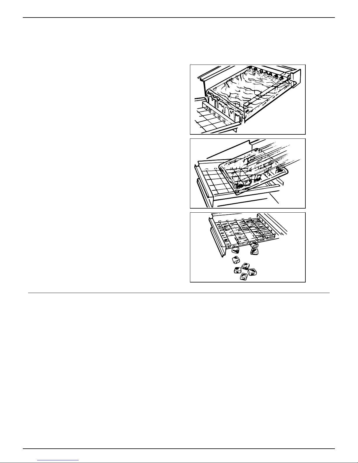
CARE AND CLEANING
Periodically inspect and clean the icemaker to keep it
operating at peak efficiency and to prevent premature
failure of system components.
Both the icemaking system and the air-cooled
condenser need to be cleaned regularly.
The minerals rejected from the circulating water
during the freezing cycle will eventually form a hard
scaly deposit in the water system which prevents a
rapid release of the ice from the freezing plate.
Clean the ice and water system periodically to remove
mineral scale build-up. Frequency of cleaning
depends on water hardness. With hard water (15 to 20
grains/gal.), cleaning may be required as frequently as
every six months.
A dirty or clogged condenser:
• prevents proper air flow.
• reduces icemaking capacity.
• causes higher than recommended operating
temperatures which may lead to component failure.
Cleaning Outside Surfaces
Wash the outside enamel surfaces and gaskets with warm water and mild
soap or detergent. Rinse and dry. Regular use of a good household
appliance cleaner and wax will help protect the finish.
Do not use abrasive cleaners on enamel surfaces as they may scratch
the finish.
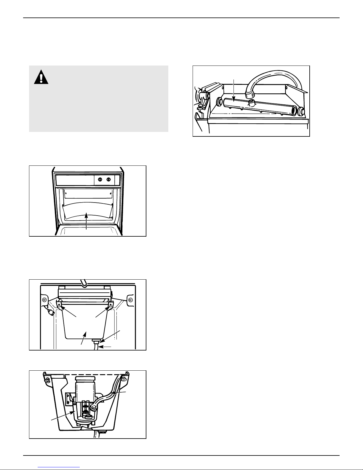
Cleaning the Condenser
WARNING:
• Be sure the icemaker is OFF and
disconnected from the main power
supply. The icemaker could suddenly start if
not disconnected. Condenser fan rotation,
sharp condenser fins and hot tubing could
cause personal injury .
• Condenser fins can bend easily. Use care
when vacuuming the condenser to keep from
bending the fins.
1. Disconnect the electrical power supply to the
icemaker and turn the Cycle Control Knob to “OFF.”
2. Remove the screw from the top of the lower access
panel and the two screws from the grille area of the
lower access panel.
3. Pull forward at the bottom, then down to remove
the panel.
4. Remove dirt and lint from the condenser fins and
the icemaker compartment with a brush attachment
attached to a vacuum cleaner.
5. Replace the lower access panel and screws. The
top of the access panel needs to be secured under
the two metal tabs before replacing the screws.
6. Plug icemaker in and turn the Cycle Control Knob
to “ON.”
Lower
Access
Panel
Grill
Area
Screw
Screws
(continued next page)
7
Page 8

CARE AND CLEANING
Cleaning the Icemaker System
WARNING: Most ice machine cleaners
are citric or phosphoric acid which can
cause irritation even after dilution. In
case of contact with eyes, flush eyes thoroughly
with fresh water and contact a physician
immediately. In case of contact with skin, rinse
well with water. If swallowed, give large
amounts of water and contact a physician
immediately. Do not induce vomiting. KEEP
OUT OF REACH OF CHILDREN.
(continued)
THIN
NORMAL
ICE
THICK
OFF
ON
CLEAN
CYCLE
1. Turn the Cycle Control Knob to “OFF.”
NORMAL
Electrical
Harness
Screws (long)
ON
THIN
OFF
THICK
CLEAN
ICE
CYCLE
2. Remove the two screws and slide the ice cutter grid
forward, out of the two slots near the water pan.
3. Unplug the electrical harness.
CAUTION: Any ice on the grid should be
melted under running warm water. Attempting
to pick the ice slab off the grid may stretch and
damage the grid wires.
4. Remove all ice from the storage bin and the
freezing plate.
Screws
Drain
Plug
Water Pan
5. Drain the water pan by removing the drain plug
and then replace the plug.
6. Pour 1/2 gallon (1.9 L) of hot tap water into the
water pan* and turn the Cycle Control Knob to
“CLEAN.” This warms up the system to make the
cleaning solution more effective. Let circulate for
five minutes. While tap water is circulating,
prepare the cleaning solution. Mix: 6 oz. (170 g)
powdered citric or phosphoric acid into 1/2 gallon
(1.9 L) hot water. (Citric and phosphoric acid
crystals are available or can be ordered from many
pharmacies or scientific supply houses.)
Commercial ice machine cleaners (liquid) are also
available from your dealer or refrigeration parts
supply stores. Mix according to instructions on
label (total quantity 1/2 gallon [1.9 L]).
7. Turn the Cycle Control Knob to “OFF” and drain
the water pan. (See step 5.)
8. Turn the Cycle Control Knob to “CLEAN”
and slowly pour the hot cleaning solution into
the water pan.* (If the solution foams while
pouring, wait until the foaming stops.) Then add
the balance of the solution.
Allow the solution to circulate until the scale has
dissolved (15 to 20 minutes). Severe scale buildup may require repeated cleaning with a fresh
quantity of cleaning solution.
To clean scale off the side flanges of the freezing
plate, use rubber gloves and scrub with a nonabrasive plastic scrubbing pad or nylon brush
dipped in cleaning solution.
9. Keep rubber gloves on to drain the cleaning
solution. Turn the Cycle Control Knob to “OFF”
and drain the water pan. (See step 5.)
10. Replace the plug and add 1/2 gallon (1.9 L) of
fresh water.* Set Cycle Control Knob on
“CLEAN,” circulate five minutes and drain.
Repeat rinsing process.
*For easier pouring of water and cleaning solution,
use a 1- or 2-cup container.
8
Page 9
Cleaning the Inside Parts of the Icemaker
WARNING:
• Do not operate the icemaker with the
lower access panel or control panel
removed. Electrical shock or personal injury
could result.
• Do not wash plastic parts in dishwasher.
They cannot withstand temperatures above
145°F. (63°C.).
1. Turn the Cycle Control Knob to “OFF” and
disconnect the electrical power supply to the
machine. Open the storage bin door and remove
any ice that is in the bin.
NORMAL
ON
THIN
OFF
THICK
CLEAN
ICE
CYCLE
Ice Retainer Baffle
2. Remove the ice retainer baffle by flexing it and
then slide it off the studs.
3. Remove the ice cutter grid by unscrewing the two
screws, sliding the grid forward and unplugging
the electrical wire harness.
Screws
Drain
Plug
Water Pan
Insert into
drain
4. Remove the water pan by unscrewing and
removing the two screws and washers.
Water Distributor
6. Remove the water distributor from the freezing
plate. It is held in place by rubber end caps.
Remove the inlet hose and clean all water
distributor holes and the small orifice in the inlet
side of the distributor. When replacing the
distributor, make sure the end caps are located in
the evaporator flange detents and that the water
distributor holes face down.
7. Wash the interior components (ice retainer baffle,
cutter grid, water pan, inlet hose and water
distributor) and the storage bin, door gasket and
ice scoop with mild soap or detergent and warm
water. Rinse in clean water. These components
should also be cleaned in a solution of 1 oz.
(29.6 ml) of chlorine bleach in 1 gallon (3.8 L)
warm water. Rinse again thoroughly in clean water.
8. Replace the interior components: water
distributor, inlet hose and water pan.
9. Check the following:
• The hose from the water valve is in the water pan.
• The rubber drain plug is in the water pan.
• The water distributor is seated and the holes are
facing down.
• The hose is reconnected to the pump and the
water distributor.
• The hose from the water pan is inserted into the
storage bin drain opening.
10. Reconnect the electrical harness, slide the cutter
grid into place and tighten the screws. Replace
the ice retainer baffle.
11. Turn Cycle Control Knob to “ON.”
Water
Pump
5. Remove the hose from the water pump.
(continued next page)
Hose
9
Page 10

CARE AND CLEANING
Filtering and Treating Water
(continued)
In most areas it will be beneficial to filter or treat the
water being supplied to the icemaker. It can improve
the reliability of the icemaker, reduce water system
maintenance and produce the best quality of ice.
The installation of a polyphosphate feeder will
generally reduce scale build-up and the icemaker will
require less frequent cleaning.
Changing the Light Bulb
WARNING: Before removing the light
bulb, either unplug the icemaker or
disconnect the electricity leading to
the icemaker at the main power supply.
Shock and injury can occur if electricity
remains connected.
The icemaker has a light bulb in the top of the storage
bin. To replace it, open the bin door and follow these
instructions:
1. Disconnect the icemaker from the power supply.
2. Remove the two screws and slide the ice cutter grid
forward, out of the two slots near the water pan. Set
the ice cutter grid on the bin door.
3. Press the front of the light shield in while pulling
down to remove it from the light bracket.
4. Remove the bulb. Replace it with a 15-watt bayonet
base type bulb.
5. Replace the light shield, ice cutter grid and two
screws.
6. Reconnect the power supply.
Municipal water systems are generally treated with
chlorine to maintain a safe drinkable water supply.
Activated carbon filters will sufficiently remove the
residual chlorine from the water to reduce surface
staining of stainless steel materials in the icemaker.
For more information on filtering and treating the
water, see the dealer from whom you purchased
your icemaker.
NORMAL
ON
THIN
OFF
THICK
CLEAN
ICE
CYCLE
Light
Switch
Screws
Light
Bracket
Light
Shield
10
Page 11

Unpacking the Icemaker
PREPARATION
1. Lay the carton on rear face and break open the
bottom flap.
2. Set the carton
upright with all
four flaps outward.
3. Lift carton up and
off icemaker.
Open Bottom
Flaps
4. Remove all tape and
packaging material from
the outside and inside of
the cabinet.
5. Remove the front grille; take
out the screws securing the
grille at the bottom and lift it
free of the cabinet.
6. Turn the fan by hand to make certain it moves freely.
Location Leveling
THIS ICEMAKER MUST BE INSTALLED IN AN
AREA PROTECTED FROM THE ELEMENTS,
SUCH AS WIND, RAIN, WATER SPRAY OR DRIP.
1. Place the icemaker so the front side will be
completely unobstructed to provide proper air flow.
2. The area should be well ventilated with temperature
above 55°F. (13°C.) and below 110°F. (43°C.). Best
results are obtained between 70°F. (21°C.) and
90°F. (32°C.).
3. Provision for electricity, water and drain
connections should be determined.
4. The icemaker may be closed in on the top and three
sides, but the front MUST BE unobstructed for air
circulation and proper operation. Installation should
be such that the cabinet can be moved forward for
servicing, if necessary.
1. After placing the icemaker into position, check to
make certain the icemaker is level side to side and
front to back.
2. Accurate leveling is essential for proper operation.
3. The icemaker should be shimmed so that it is solid
as well as level. The shims should be of hard
permanent type material such as masonite.
4. Compliance with National Sanitation Foundation
standards requires that this type of product be
sealed to the floor at the bottom rail in order to
prevent contamination from spills or the entrance
of vermin. Therefore, we recommend that when
installing the icemaker you seal it to the floor in
accordance with those standards. A silicone-type
sealer is recommended.
Remove
Interior
Packing
Thermostat Calibrations
If the icemaker is installed above two thousand feet of altitude, the bin and
evaporator thermostats must be adjusted to a warmer setting. Disconnect
electricity, remove thermostat and follow the directions for turning the
altitude adjustment screw as shown in the label on each thermostat.
(continued next page)
11
Page 12

PREPARA TION
Changing the Bin Door Panel
You can easily change the color of the front panel on
the storage bin door. Two colors are available: black
and white.
To change the panel:
1. Open the storage bin door. Remove the two screws
on the top of the door which hold the handle.
2. Loosen the screws in both of the side trim pieces.
3. Remove the handle and the handle insert.
4. Carefully slide the panel out. You will find the
reverse side is black. For units with black panels
showing, the reverse side will be white.
5. Choose the color you want to show and carefully
slide the panel back into the door.
NOTE: Be careful not to scratch the panel as it is
inserted.
6. Replace the handle insert and tighten the screws in
both side trim pieces. Replace the handle and screws.
NOTE: You can make a decorative wood front to
match existing cabinets. See the section on Custom
Door and Access Panels.
(continued)
Handle
Handle
Insert
12
Page 13
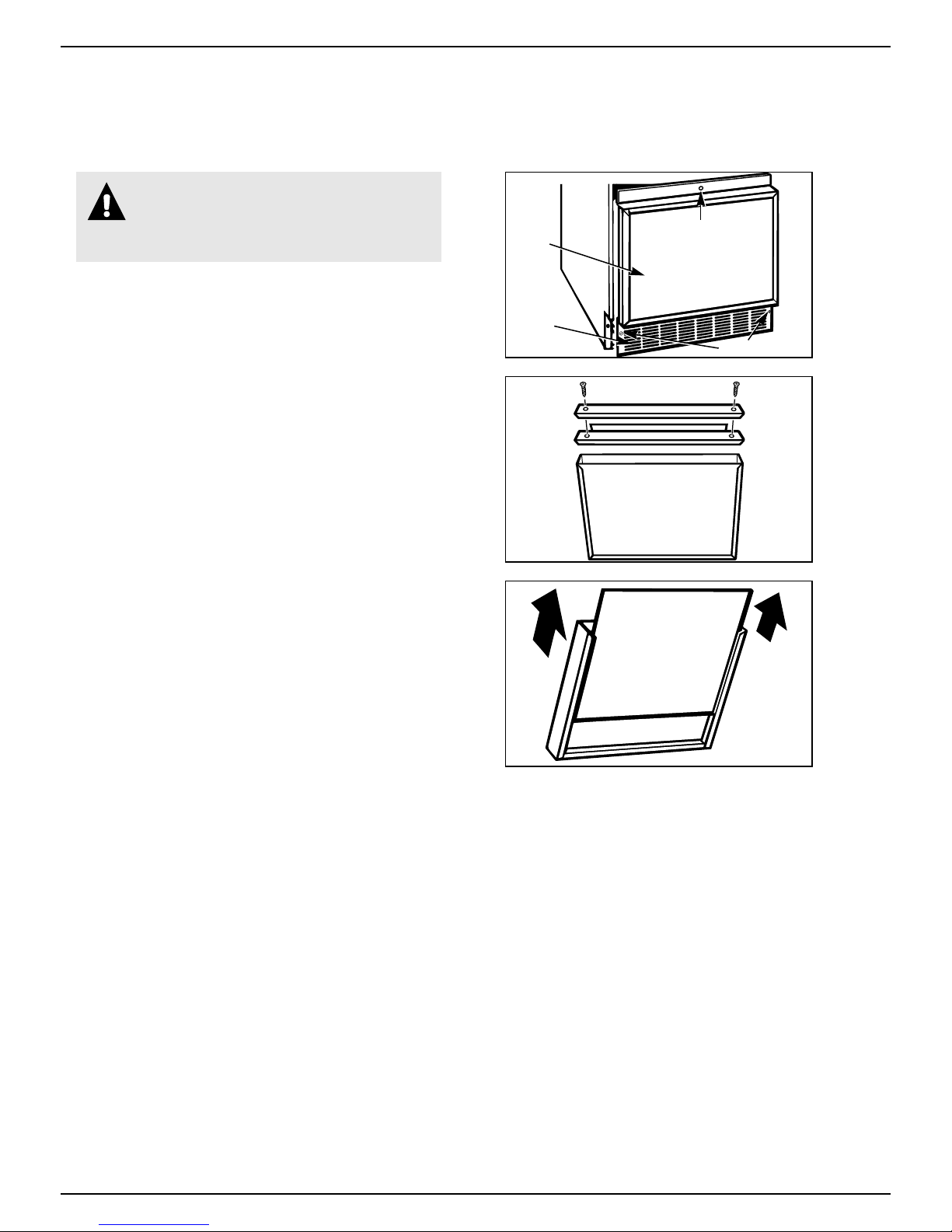
Changing the Lower Access Panel
WARNING: Do not operate the
icemaker with the lower access panel or
control panel removed. Electrical shock
or personal injury could result.
1. Remove the screw from the top of the lower access
panel and the two screws in the bottom grille area.
Pull forward at the bottom, then down to remove
the panel.
2. Remove the two screws from the top panel trim and
remove the top trim.
3. Carefully slide the panel out.
4. Choose the color you want to show and carefully
slide the panel back into the lower access panel.
NOTE: Be careful not to scratch the panel as it
is inserted.
5. Replace the top trim and screws. Replace the lower
access panel assembly and screws. The top of the
access panel needs to be secured under the two
metal tabs before replacing the screws.
NOTE: You can make a decorative wood front to
match existing cabinets. See the section on Custom
Door and Access Panels.
Lower
Access
Panel
Grill
Area
Screw
Screws
(continued next page)
13
Page 14
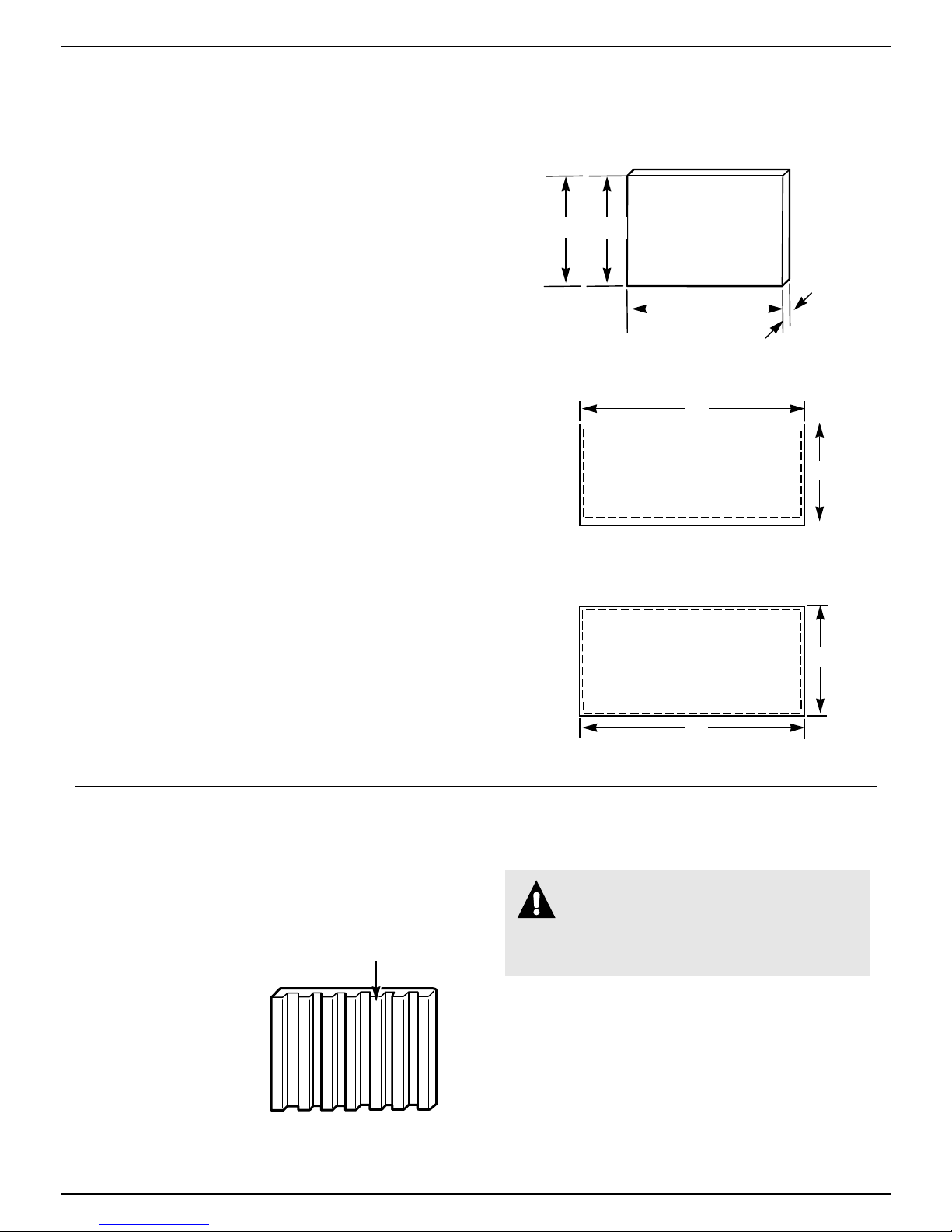
CUSTOM DOOR AND ACCESS PANELS
Custom Door and Access Panels—1/4″ Thick
Cut panels to the same size as the production
metal panel.
Door
Bin
111/4″
Lower
Panel
1115/16″
Wood Panel
Dimensions
1/4″
17″
Custom Door and Access Panels—3/4″ Thick
These door and access panels—both raised and flat
design—should be constructed in the same manner as
typical cabinet doors or drawers.
Storage bin door panel:
• Cut the panel 17″ wide x 11
1
/4″ high.
• Rout the top and both sides 5/16″ wide, 1/2″ deep
for a total thickness of 1/4″.
• Rout the bottom of the panel 1″ wide, 1/2″ deep for
a total thickness of 1/4″. This will allow the door to
open without binding against the lower panel. For a
custom appearance, consider tapering this 1″ rout.
Lower access panel:
• Cut the panel 17″ wide x 11
15
/16″ high.
• Rout all four sides 5/16″ wide and 1/2″ deep for a
total thickness of 1/4″.
Install Custom Door and Access Panels
To install the storage bin door panel:
1. Open the storage bin door.
2. Remove the two screws on top
of the door which hold the handle.
3. Remove the handle.
Remove all door
insulation ribs to
accept wood
panel thickness
4. Slide the metal panel out.
5. Break off the ribs on
the door insulation to
allow for the wood
thickness.
6. Slide the wood panel
into the door frame.
7. Replace the handle
and screws.
14
17″
Storage Bin Door Panel
Rout 1/2″ deep, 1″ wide across bottom
Rout 1/2″ deep, 5/16″ wide top and sides
Rout 1/2″ deep, 5/16″ wide on all sides
Lower Access Panel
17″
3/4″ Thick Panels
111/4″
1115/16″
To install the lower access panel:
WARNING: Make sure the icemaker is
disconnected from the main power supply
before removing the lower access panel.
Failure to do so could result in electric
shock or personal injury .
1. Remove the screw at the top of the lower access
panel assembly and the two screws at the bottom that
hold the lower access panel assembly to the icemaker.
2. Remove the two screws from the top panel trim.
3. Slide the metal panels and spacers out.
4. Slide the wood panel into the door frame.
5. Replace the top of the panel assembly.
NOTE: Make sure the galvanized panel is replaced
in back of the panel assembly.
Page 15

Vacation and Moving
WARNING: Make sure the icemaker is
disconnected from the main power supply
before removing the lower access panel.
Failure to do so could result in electric
shock or personal injury .
To shut down the icemaker:
1. Disconnect the electrical power supply to the
icemaker and turn the Cycle Control Knob to “OFF.”
2. Remove all ice from the storage bin.
3. Shut off the water supply.
4. Remove the screw from the top of the lower access
panel and the two screws from the grille area of the
lower access panel, then remove the panel. Pull
forward at the bottom, then down.
THIN
Lower
Access
Panel
Grille
Area
NORMAL
ICE
THICK
OFF
ON
CLEAN
CYCLE
Screw
Screws
5. Disconnect the inlet and outlet lines to the water
valve. Allow these lines to drain and then reconnect
to the valve.
6. Replace the lower access panel and screws. The
top of the access panel needs to be secured under
the two metal tabs before replacing the screws.
7. Remove water from the drain lines and drain
water pan.
8. Before using again, clean the icemaker and
storage bin.
NOTE: All components of the icemaker are
permanently lubricated at the factory. They should
not require any additional oiling throughout the
normal life of the machine.
Outlet
Inlet
Water
Pan
15
Page 16

FREE STANDING INST ALLATION
For the Installer
When this icemaker is installed free standing (not under a counter) we
strongly recommend that the bottom rear corners of the icemaker be
fastened to the floor to prevent accidental tipping.
INSTALLA TION REQUIREMENTS
IMPORTANT…Please Read Carefully
For the Electrician—Electrical Requirements
A 115 Volt, 60 Hz, AC only, 15 Amp fused electrical supply is required
(time delay fuse or circuit breaker is recommended). It is recommended that
a separate circuit, serving only this appliance, be provided. DO NOT use an
extension cord.
ELECTRICAL GROUND IS REQUIRED ON THIS APPLIANCE.
Recommended Grounding Methods
DO NOT, UNDER ANY CIRCUMSTANCES,
REMOVE THE POWER SUPPLY CORD
GROUND PRONG.
For your personal safety, this appliance must be
properly grounded.
This appliance is equipped with a power supply cord
having a 3-prong grounding plug. To minimize
possible shock hazard, the cord must be plugged into
a mating 3-prong grounding type wall receptacle,
grounded in accordance with the National Electrical
Code and local codes and ordinances. If a mating wall
receptacle is not available, it is the personal
responsibility and obligation of the customer to have a
properly grounded 3-prong wall receptacle installed
by a qualified electrician.
3-Prong
Grounding Type
Wall Receptacle
3-Prong
Grounding
Plug
Power Supply
Cord
16
Page 17

INSTALLA TION INSTRUCTIONS
13
/32″
Back view
7
3/4″
1/4″ O.D.
water line
compression
fitting at
water valve
Figure 1
Right end view
7
/8″
23
Water inlet
solenoid valve
3
/4″
1
7
/2″
Bend field supplied water line to
connect to water valve fitting
3
34
21/2″
UTILITIES
OBSERVE LOCAL CODES
Each installation is unique but will require:
• A cold water inlet of 1/4″ O.D. soft copper
tubing and a shutoff valve.
• Either a gravity drain system or a sump pump
to lift the water to an existing drain.
• An electrical branch circuit of 115 volt, 60 Hz.
1 phase, with a 15 amp delayed action fuse or
circuit breaker.
FOR THE PLUMBER
Connect to water. (Observe local codes.)
• Use 1/4″ O.D. soft copper tubing for the cold
water supply.
Provide a convenient manual shutoff valve in the
•
water line.
• Position the tubing so it can enter the access
hole located in the right-hand rear of the
icemaker cabinet. The tubing should extend
beyond the cabinet front so when the icemaker
is pushed back in position it will reach the water
inlet location in the front. See Figure 1.
NOTE: Always purge the water line before
making the final connection to the inlet of the
water valve to prevent possible water valve
malfunction.
With the icemaker in its permanent location,
bend the tubing to meet the connection at
the water valve. The garden hose threaded
compression fitting is found in the parts bag.
This joint provides a convenient disconnect
for service. Be sure the tubing is clear of
compressor, to prevent rattle.
1
/2″
3/4″
17
7
/8″
4″ long 5/8″ I.D.
9″
rubber drain
tube—run to
open drain
11/4″ Min.
Hole for field
supplied water line
90°
Figure 2
341/2″
9″
Max.
center line
18″
4
1
/2″ to
90°
LEVELING
• After placing the icemaker into position, check
to make certain the icemaker is level side to side
and front to back.
• Accurate leveling is essential for proper
operation.
• The icemaker should be shimmed so that it is
solid as well as level. The shims should be of
hard permanent type material such as masonite.
• Compliance with National Sanitation
Foundation standards requires that this type of
product be sealed to the floor at the bottom rail
in order to prevent contamination from spills or
the entrance of vermin. Therefore, we
recommend that when installing the icemaker
you seal it to the floor in accordance with those
standards. A silicone-type sealer is recommended.
ALTERNATE METHOD
If a drain connection directly below the
drain tube outlet is not available, install a
UL-listed drain pump in the rear compartment
of the icemaker.
Drain pump specifications:
• UL-listed and have a UL-listed, 120VAC, 3-wire
grounded service cord
• Overall outside dimensions (maximum):
15″ wide x 6″ deep x 9
• Pump flow rate (minimum): 24.0 gph (0.4 gpm)
@ 12 feet lift
• Operating temperature range 55°F. to 110°F.
(13°C. to 43°C.)
1
/2″ high
(continued next page)
17
Page 18

INSTALLA TION INSTRUCTIONS
(continued)
DRAIN PUMP
• When the drain connection is below the level of
the icemaker, a drain pump may be used to lift the
water to an available drain. Use only an approved
drain pump kit ZDK50 from your dealer.
• Complete installation instructions are included
with the drain pump kit.
CHECK OPERATION
• Start the icemaker by turning the service
switch to “ON” and opening the line water valve.
• NOTE: Left is “OFF”—Middle is “ON”—Right
is “CLEAN.” In “CLEAN” position, only the
pump operates.
• Check the condenser fan to make sure it is
revolving.
• Water will not enter the pump pan until the
freezing plate gets cold and the icemaker goes
into a harvest cycle.
• Check for even water flow over the freezing
plate. The icemaker must be level for proper
operation.
• Check for desired cube thickness and after 24
hours adjust if necessary. Maximum ice yield will
be obtained with ice thickness at 1/2″ to 5/8″.
• Replace the grille.
18
Page 19

QUESTIONS?
USE THIS PROBLEM SOLVER
PROBLEM POSSIBLE CAUSE
ICEMAKER DOES • Cycle Control Knob must be in the “ON” position.
NOT RUN
ICEMAKER RUNS BUT • Cycle Control Knob must be in the “ON” position.
PRODUCES NO ICE
ICEMAKER RUNS • Room temperature may be extremely high, more that 90°F. (32°C.). In this case
BUT PRODUCES it is normal for ice production to be low.
VERY LITTLE ICE
• Check to see that the power cord is plugged in.
• Have you checked your home’s main fuses or circuit breaker box?
• Room temperature must be above 55°F. (13°C.). Otherwise, the bin thermostat
may sense the cold room temperature and shut off even though the bin is not
full of ice. Also, the icemaker may not restart once it does shut off.
• Check water supply to make sure it is open.
• If the icemaker is operated at an elevation of 2,000 feet or more above sea level,
both the bin thermostat and ice thickness thermostat need to be recalibrated.
See the Installation Instructions.
• Dirt or lint may be blocking the air flow through the finned condenser.
Condenser needs to be cleaned.
• Check to see if the icemaker has a scale build-up in water and freezing system.
Clean if necessary.
GRID IS NOT CUTTING • Check the grid harness plug to make sure the connection is secure.
ICE SHEETS
TASTE IN ICE CUBES • There may be an unusually high mineral content in the water supply. Water may
need to be filtered or treated.
• Do not store any foods in the ice bin.
• Packaging material not all removed.
If you need more help…call, toll free:
GE Answer Center
consumer information service
®
, 800.626.2000
19
Page 20

We’ll Be There
With the purchase of your new GE appliance, receive the assurance that if you ever need
information or assistance from GE, we’ll be there. All you have to do is call—toll-free!
GE Answer Center®
800.626.2000
Whatever your question about any GE major appliance, GE Answer Center®
information service is available to help. Your call—and your question— will be
answered promptly and courteously. And you can call any time. GE Answer
Center® service is open 24 hours a day, 7 days a week.
In-Home Repair Service
800-GE-CARES (800-432-2737)
A GE consumer service professional will provide expert repair service,
scheduled at a time that’s convenient for you. Many GE Consumer Service
company-operated locations offer you service today or tomorrow, or at your
convenience (7:00 a.m. to 7:00 p.m. weekdays, 9:00 a.m. to 2:00 p.m. Saturdays).
Our factory-trained technicians know your appliance inside and out—so most
repairs can be handled in just one visit.
For Customers With Special Needs…
800.626.2000
6’ 10"
Upon request, GE will provide
Braille controls for a variety of
GE appliances, and a brochure to
assist in planning a barrier-free
kitchen for persons with limited
1"
SCALE 1’
=
mobility. To obtain these items,
Consumers with impaired hearing or speech who have
access to a TDD or a conventional teletypewriter may
call 800-TDD-GEAC (800-833-4322) to request
information or service.
SINGLE CONTROL
FAUCET
8"
5"
1/8
3’
"
R SHALLOW DEPTH SINKS (6") WITH REAR DRAIN.
SINK SHOULD ALSO BE UNDERCOATED
SECTION A-A
2’ 6"
TBXTOLITE
ON WALL
6"
5"
1’ 0"
7"
FLUORESCENT
FIXTURE
THIS LIGHT CAN
BE INSTALLED
IN BOTTOM OF
WALL CABINETS
2’ 10"
free of charge, call 800.626.2000.
Service Contracts
800-626-2224
You can have the secure feeling that GE Consumer Service will still be there
after your warranty expires. Purchase a GE contract while your warranty is still
in effect and you’ll receive a substantial discount. With a multiple-year contract,
you’re assured of future service at today’s prices.
Parts and Accessories
800-626-2002
Individuals qualified to service their own appliances can
have parts or accessories sent directly to their home. The
GE parts system provides access to over 47,000 parts…and
all GE Genuine Renewal Parts are fully warranted. VISA,
MasterCard and Discover cards are accepted.
User maintenance instructions contained in this booklet
cover procedures intended to be performed by any user.
Other servicing generally should be referred to qualified
service personnel. Caution must be exercised, since
improper servicing may cause unsafe operation.
20
Page 21

YOUR GE ICEMAKER
WARRANTY
Staple sales slip or cancelled check
here. Proof of original purchase date
is needed to obtain service
under warranty.
WHA T IS COVERED
FULL ONE-YEAR WARRANTY
For one year from date of original
purchase, we will provide, free of
charge, parts and service labor in
your home to repair or replace
part of the icemaker
because of a manufacturing defect.
FULL FIVE-YEAR WARRANTY
For five years from date of original
purchase, we will provide, free of
charge, parts and service labor in
your home to repair or replace any
part of the sealed icemaking
system (the compressor,
condenser, evaporator and all
connecting tubing) that fails
because of a manufacturing defect.
that fails
any
******************************
This warranty is extended to
the original purchaser and any
succeeding owner for products
purchased for use in the 48
mainland states, Hawaii and
Washington, D.C. In Alaska the
warranty is the same except that it
is LIMITED because you must pay
to ship the product to the service
shop or for the service technician’s
travel costs to your home.
All warranty service will be
provided by our Factory Service
Centers or by our Authorized
Customer Care®servicers during
normal working hours.
Should your appliance need
service, during warranty period
or beyond, call 800-GE-CARES
(800-432-2737).
WHA T IS NOT COVERED
• Service trips to your home to
teach you how to use the
product.
Read your Use and Care material.
If you then have any questions
about operating the product please
contact your dealer or our
Consumer Affairs office at the
address below, or call, toll free:
GE Answer Center
800.626.2000
consumer information service
Some states do not allow the exclusion or limitation of incidental or consequential damages, so the above limitation or exclusion
may not apply to you. This warranty gives you specific legal rights, and you may also have other rights which vary from state to state.
To know what your legal rights are in your state, consult your local or state consumer affairs office or your state’s Attorney General.
2180919
Part No. 162D7745P002
Pub. No. 49-6857
®
Manager—Consumer Affairs, GE Appliances, Louisville, KY 40225
• Improper installation.
If you have an installation problem,
contact your dealer or installer.
You are responsible for providing
adequate electrical, plumbing and
other connecting facilities.
• Replacement of house fuses or
resetting of circuit breakers.
• Use of a non-approved Drain
Pump Kit.
Warrantor: General Electric Company
If further help is needed concerning this warranty, write:
• Failure of the product if it is used
for other than its intended
purpose or used commercially.
• Damage to product caused
by accident, fire, floods or acts
of God.
• Loss of food due to spoilage.
WARRANTOR IS
RESPONSIBLE FOR
CONSEQUENTIAL DAMAGES.
NOT
ZDIB50, ZDIW50
Printed in the United States
21
Page 22

NOTES
22
Page 23

Monogram.
Manual del usuario e
instrucciones para
la instalación
para ZDIB50
ZDIW50
Máquina para hacer hielo
Monogram.
General Electric Company
Louisville, KY 40225
TM
Monogram.
Máquina para hacer hielo
Pub. No. 49-6857
Part No. 162D7745P002
TM
Page 24

Introducción
Su nueva máquina para hacer hielo Monogram es
una afirmación elocuente de estilo, comodidad y
flexibilidad en la planeación de su cocina. Ya sea
que la elija por la pureza de su diseño, por las
características físicas o por la constante atención al
detalle—o por todas estas razones—encontrará que
la conbinación de forma y función de su maquina para
hacer hielo Monogram es superior y dará una gran
satisfacción durante los años venideros.
Contenido
Cuidado y limpieza.................7–10
Cambio del bombillo ...........10
Componentes interiores de la
máquina para hacer hielo....9
Condensador ..........................7
Filtrado y tratamiento
del agua.............................10
Sistema para fabricar hielo ....8
Superficies exteriores.............7
Controles.......................................6
Características...............................6
Instrucciones de instalación..16–18
Instalación independiente ....16
Instrucciones para
la conexión a tierra............16
Requerimientos eléctricos....16
Instrucciones de operación .......5, 6
Instrucciones de seguridad............4
Localización de números de
serie y de modelos..............3, 6
La máquina para hacer hielo Monogram fue diseñada
para proporcionar la flexibilidad requerida para
adaptarse a los gabinetes de su cocina.
La información contenida en las siguientes páginas le
ayudará a operar y a mantener de manera apropiada su
máquina para hacer hielo.
Si requiere una lista de distribuidores, o si tiene otras
preguntas, por favor llamé a GE Answer Center
(800.626.2000).
Preparación ...........................11–15
Calibraciones del
termostato..........................11
Cómo cambiar el panel del
depósito de la puerta .........12
Cómo cambiar el panel
inferior de acceso..............13
Cómo desempacar la
máquina para hacer hielo ..11
Localización.........................11
Nivelación............................11
Puerta y paneles de
acceso a la medida ............14
Vacaciones y mudanzas .......15
Registro del aparato......................3
Servicios al consumidor..............20
Solución a los problemas............19
Garantía ......................................21
®
¿Preguntas?
Llamé a GE Answer Center
®
800.626.2000
2
Page 25

AYUDENOS A AYUDARLE…
Lea cuidadosamente este folleto. Anote el modelo y los números de serie.
Es nuestra intención ayudarle a operar y mantener
adecuadamente su nuevo máquina para hacer hielo.
Mantenga este folleto a la mano para responder a
sus preguntas.
Si no entendiera algo o necesitara asesoría, llame a:
GE Answer Center
800.626.2000
24 horas del día, 7 días a la semana
®
Si usted recibiera un máquina para
hacer hielo dañado…
Contacte inmediatamente al distribuidor (o al
fabricante) que le vendió la máquina para hacer hielo.
Ahorre tiempo y dinero.
Antes de solicitar el servicio…
Revise la sección de Solución de problemas de este
folleto. Allí se describen problemas de operación
menores que usted mismo puede corregir.
Los verá en la placa del lado izquierdo del depósito de
almacenamiento.
Estos números se encuentran también en la Tarjeta de
registro de propiedad del producto del consumidor que
se proporciona junto con su máquina para hacer hielo.
Antes de enviar esta tarjeta, por favor anote aquí los
siguientes números:
Número de modelo
Número de serie
Use estos números en toda correspondencia o llamada
de servicio referentes a su máquina para hacer hielo.
SI SE NECESITA SERVICIO
Para solicitar servicio, vea la página de Servicios al
consumidor al final de este folleto.
Estamos orgullosos de nuestro servicio y deseamos
quede satisfecho. Si por alguna razón usted no
quedara satisfecho con el servicio recibido, por favor
siga los tres pasos siguientes:
PRIMERO contacte a las personas que le dieron
servicio a su aparato. Explíqueles por qué no quedó
satisfecho. En la mayoría de los casos, ellos le
resolverán su problema.
A CONTINUACION, si usted siguiera insatisfecho
con el servicio, escriba todos los detalles (incluyendo
su número telefónico) a:
Manager, Consumer Relations
GE Appliances
Appliance Park
Louisville, KY 40225
FINALMENTE, si aún siguiera sin resolver el
problema, escribir a:
Major Appliance Consumer Action Program
20 North Wacker Drive
Chicago, IL 60606
3
Page 26

INSTRUCCIONES DE SEGURIDAD
Lea todas las instrucciones antes de usar este electrodoméstico.
ADVERTENCIA—Para reducir el riesgo
de incendio, choque eléctrico o lesiones
cuando esté usando su máquina para
hacer hielo, siga precauciones básicas
incluyendo las siguientes:
• Nunca permita que los niños operen, jueguen
con la máquina o se metan al interior de la
máquina.
• Nunca limpie las partes de la máquina para
hacer hielo con líquidos inflamables. Los
vapores pueden crear riesgos de incendio o
explosión.
• Por su seguridad: No almacene ni use gasolina
u otros vapores y líquidos cerca de este o de
otro aparato. Los vapores pueden crear riesgos
de incendio o explosión.
• Haga que un técnico de servicio calificado
instale y conecte a tierra la máquina para
hacer hielo de manera correcta de acuerdo
con las Instrucciones de instalación.
• No trate de reparar o reemplazar ninguna
parte de su máquina para hacer hielo a menos
que se recomiende específicamente en esta
guía. Todo otro servicio se debe remitir a
un técnico de servicio calificado.
• Es responsabilidad de usted asegurarse de que
su máquina para hacer hielo:
— se haya instalado donde esté protegida de los
elementos.
— se localice de modo que el frente no esté
obstruido de modo que no limite el flujo de
aire de entrada o de descarga.
— esté nivelada correctamente.
— esté localizada en un área bien ventilada con
temperaturas superiores a 55 °F. (13 °C.) y
menores que 110 °F. (43 °C.). Los mejores
resultados se obtienen a temperaturas entre
70 °F. (21 °C.) y 90 °F. (32 °C.).
— esté conectada de modo adecuado a una línea
de suministro de agua y a una de drenaje.
— esté conectada sólo al tipo correcto de toma de
corriente, con el suministro eléctrico correcto y
conexión a tierra correcta. Se requieren 120
voltios, 60 Hz y 15 amperes de suministro
eléctrico. NOTA: Se recomienda un fusible de
retardo o un interruptor de circuito.
— que no la use alguien que sea incapaz de
operarla de manera adecuada.
— se use sólo para el fin para el que están
diseñadas las máquinas para hacer hielo.
4
— se le dé el mantenimiento correcto.
GUARDE ESTAS
INSTRUCCIONES
Page 27

OPERACION DE SU MAQUINA PARA HACER HIELO
Cómo funciona la máquina para hacer hielo
1. El agua circula constantemente sobre una placa de
congelación. A medida que el agua se enfría para
llegar a congelarse, los minerales que contiene el
agua son expulsados. Esto produce una capa
delgada de hielo con bajo contenido de minerales.
NOTA: La máquina para hacer hielo está diseñada
para fabricar hielo transparente con la mayoría de
las fuentes de suministro de agua todos los días.
Si los resultados no son satisfactorios, el agua
puede necesitar filtrarse o tratarse. Consulte
Filtración y tratamiento del agua en la sección
Cuidado y limpieza.
2. Cuando se haya alcanzado el espesor deseado, la
placa de hielo se libera y se desliza hacia la rejilla
cortadora. Esta rejilla divide la placa de hielo en
cubos individuales.
3. El agua que contiene los minerales expulsados se
drena después de cada ciclo de congelación.
4. El agua fresca entra en la máquina para el siguiente
ciclo de congelación.
5. Los cubos caen en el depósito de almacenamiento.
Cuando el depósito está lleno, la máquina para
hacer hielo se apaga automáticamente y se vuelve a
encender cuando se necesita más hielo.
Notas acerca de esta máquina para hacer hielo
• El agua entra sólo durante el ciclo de
descongelamiento. Por lo tanto el primer ciclo se
acabará sin tener agua en el sistema.
• Como las temperaturas ambiente y del agua varían,
así también variará la cantidad de hielo producido.
Eso significa que las temperaturas de operación más
altas resultarán en producción de hielo reducida.
• La máquina para hacer hielo se apagará cuando el
hielo en el depósito de almacenamiento toca la
fuente del termostato del depósito y ciclará
automáticamente para mantener lleno el depósito.
• El depósito de almacenamiento no se refrigera y
algún derretimiento ocurrirá. Eso, también, varía con
la temperatura ambiente.
• La máquina para hacer hielo necesita buena
circulación de aire para funcionar eficazmente.
Mantenga limpios la rejilla frontal y el condensador.
• El sistema de agua, incluyendo el filtro dentro de la
válvula de solenoide de entrada de agua, se necesita
limpiar periódicamente para buena circulación. Las
instrucciones se encuentran en el panel de la puerta
interior.
(pase a la página siguiente)
5
Page 28

OPERACION DE SU MAQUINA PARA HACER HIELO
(pase)
Ajustando los controles
1. Elija el espesor de hielo que desee. La máquina
para hacer hielo ha sido ajustada en la fábrica para
producir hielo de aproximadamente 1/2″ (13 mm)
de espesor, siempre que esté operando a una
temperatura ambiente de 70 °F. (21 °C.).
La operación a una temperatura ambiente distinta
puede requerir un reajuste del control ya sea hacia
la posición “THICK” (grueso) o “THIN” (delgado).
La mejor operación se obtendrá con hielo de 1/2″
(13 mm) hasta 5/8″ (16 mm) de grueso.
Si su máquina opera en una habitación tibia (más
de 90 °F. [32 °C.]) NO coloque el control en el
espesor máximo ya que podría causar un mal
funcionamiento de la máquina para hacer hielo.
2. Para iniciar el ciclo normal de fabricación de hielo,
haga girar la perilla de Control de ciclo hasta la
posición “ON” (encendido).
3. Para detener la operación de la máquina para hacer
hielo, haga girar la perilla de Control de ciclo hasta
la posición “OFF” (apagado).
La posición de “CLEAN” (limpiar) se usa siempre
que hayan circulado impurezas a través de la
máquina para hacer hielo durante la limpieza de
ésta. Sólo la bomba de agua funciona en esta
posición de la perilla. Consulte Limpieza del sistema
de la máquina para hacer hielo en la sección Cuidado
y limpieza, si requiere de instrucciones específicas.
THIN
THIN
NORMAL
ICE
NORMAL
ICE
THICK
THICK
OFF
OFF
ON
CLEAN
CYCLE
ON
CLEAN
CYCLE
6
CARACTERISTICAS DE SU MAQUINA
PARA HACER HIELO
Control de espesor
del hielo
Placa con el
número de
serie y modelo
(no se muestra)
Placa
retenedora
del hielo
Panel
inferior de
acceso
ON
NORMAL
CLEAN
OFF
THICK
THIN
CYCLE
ICE
Perilla de
control de ciclo
Luz del depósito
Depósito para hielo
Cuchara para
hielo
Page 29

CUIDADO Y LIMPIEZA
Inspeccione y limpie periódicamente la máquina para
hacer hielo de modo que siga funcionando a su
máxima eficiencia y para prevenir una falla prematura
de los componentes del sistema.
Tanto el sistema de fabricación de hielo como el
condensador enfriado por aire necesitan ser limpiados
de manera regular.
Los minerales expulsados del agua circulante durante
el ciclo de congelación a la larga formarán un depósito
escamoso duro en el sistema de agua que evitará la
liberación rápida del hielo de la placa de congelación.
Limpieza de las superficies exteriores
Lave las superficies exteriores de esmalte y los empaques
con agua tibia y jabón o detergente suave. Enjuague y
seque. El uso regular de un buen limpiador doméstico
para aparatos y de cera ayudará a proteger el acabado.
Limpieza del condensador
ADVERTENCIA:
• Asegúrese de que la máquina para
hacer hielo esté en posición de “OFF”
(apagado) y desconectada del suministro
principal de energía eléctrica. La máquina
podría encenderse súbitamente si no está
desconectada. La rotación de las aspas del
condensador, las afiladas hojas del
condensador y las tuberías calientes podrían
causar lesiones permanentes en las personas.
• Las hojas del condensador pueden doblarse
con facilidad. Tenga cuidado cuando limpie
con aspiradora el condensador para evitar
que las hojas se doblen.
Limpie periódicamente el sistema de hielo y agua
para quitar las sales minerales escamosas que se
forman. La frecuencia con que se haga la limpieza
dependerá de la dureza del agua. Si el agua es dura
(15/20 granos/galón), la limpieza puede requerirse
con tanta frecuencia como lo sería cada seis meses.
Un condensador sucio o tapado:
• evita el flujo correcto de aire
• reduce la capacidad de fabricar hielo
• causa temperaturas de operación superiores a las
recomendadas que pueden llevar a una falla de los
componentes.
No use limpiadores abrasivos en superficies
esmaltadas ya que pueden rayar el acabado.
Panel
inferior de
acceso
Area de
la rejilla
Tornillo
Tornillos
1. Desconecte el suministro de corriente eléctrica que
alimenta la máquina para hacer hielo y ponga la
perilla de Control de ciclo en “OFF” (apagado).
2. Quite los dos tornillos del área de la rejilla en el
panel inferior de acceso.
3. Tire hacia adelante y hacia abajo para quitar el panel.
4. Quite la suciedad y la pelusa de las hojas del
condensador y del compartimiento de la unidad con
un accesorio para cepillar conectado a una aspiradora.
5. Vuelva a colocar el panel inferior de acceso y los
tornillos. La parte superior del panel de acceso
necesita asegurarse debajo de las dos lengüetas
de metal antes de volver a colocar los tornillos.
6. Conecte la máquina para hacer hielo y haga girar la
perilla de Control de ciclo hasta la posición de
“ON” (encendido).
(pase a la página siguiente)
7
Page 30

CUIDADO Y LIMPIEZA
(pase)
Limpieza del sistema de la máquina para hacer hielo
ADVERTENCIA: La mayoría de los
limpiadores para máquinas se hacen a
base de ácido cítrico o fosfórico y
pueden causar irritación incluso después de ser
diluidos. En el caso de contacto con los ojos,
enjuague los ojos meticulosamente con agua y
llame a un médico de inmediato. En caso de
contacto con la piel, enjuague bien con agua. Si
se ingiere, déle a la persona grandes cantidades
de agua y llame a un médico de inmediato. No
induzca el vómito. MANTENGASE FUERA
DEL ALCANCE DE LOS NIÑOS.
1. Coloque la perilla de Control de ciclo en posición
de “OFF” (apagado).
NORMAL
Colector del
cableado eléctrico
Tornillos (largos)
ON
THIN
OFF
THICK
CLEAN
ICE
CYCLE
2. Quite los dos tornillos y deslice la rejilla cortadora
de hielo hacia adelante, sacándola de las dos
ranuras cercanas a la bandeja para agua.
3. Desconecte el colector del cableado eléctrico.
PRECAUCION: Cualquier cantidad de hielo
que quede en la rejilla deberá derretirse bajo
agua tibia corriente. Si trata de quitar los
trozos de hielo de la rejilla puede estirar y
dañar los alambres de la rejilla.
4. Quite todo el hielo del depósito de hielo y de la
placa de congelación.
Tornillos
Tapón del
desagüe
Bandeja para agua
5. Drene la bandeja para agua quitando el tapón de
desagüe y luego vuelva a colocarlo.
8
6. Vierta 1/2 galón
(1.9 L) de agua
NORMAL
ON
caliente del grifo
en la bandeja para
THICK
OFF
CLEAN
agua* y haga girar
la perilla de Control
de ciclo hasta la
ICE
CYCLE
posición “CLEAN”
(limpiar). Esto calentará el sistema para hacer más
efectiva la acción de la solución limpiadora. Deje
que circule durante cinco minutos. Mientras el agua
del grifo está circulando, prepare la solución
limpiadora. Mezcle 6 onzas (170 g) de ácido cítrico
o fosfórico en polvo con 1/2 galón (1.9 L) de agua
caliente. (Los cristales de ácido cítrico y fosfórico
están disponibles o pueden ordenarse en muchas
farmacias y tiendas de materiales científicos.)
Los limpiadores comerciales para máquinas de
hacer hielo (líquidos) también los tiene su
distribuidor o las tiendas que venden partes para
refrigeración. Mezcle de acuerdo con las
instrucciones de las etiquetas (la cantidad total
debe ser de 1/2 galón [1.9 L]).
7. Haga girar la perilla de Control de ciclo hasta la
posición “OFF” (apagado) y desagüe la bandeja
de agua. (Vea el paso 5.)
8. Coloque la perilla de Control de ciclo en “CLEAN”
(limpiar) y vierta lentamente la solución limpiadora
caliente en la bandeja para agua.* (Si la solución
hace espuma mientras la está vertiendo, espere
hasta que deje de hacer espuma.) Luego añada lo
que queda de la solución.
Permita que la solución circule hasta que se hayan
disuelto los residuos acumulados (de 15 a 20
minutos). Una formación de residuos escamosos
muy grande puede requerir de una limpieza repetida
con una cantidad de solución limpiadora nueva.
Para limpiar las acumulaciones en las pestañas
laterales de la placa de congelación utilice
guantes de hule y talle con una fibra plástica no
abrasiva o con un cepillo de nylon empapado en
solución limpiadora.
9. No se quite los guantes de hule cuando drene la
solución limpiadora. Coloque la perilla de Control
de ciclo en “OFF” (apagado) y vacíe la bandeja
para agua. (Vea el paso 5.)
10. Vuelva a colocar el tapón y agregue 1/2 galón
(1.9 L) de agua limpia.* Haga girar la perilla de
Control de ciclo hasta la posición “CLEAN”
(limpiar), deje que circule durante 5 minutos y
luego drene. Repita el proceso de enjuague.
*Para facilitar el vertido del agua y de la solución
limpiadora use un recipiente con capacidad para 1 o
2 tazas.
Page 31

Limpieza de los componentes interiores
ADVERTENCIA:
• No opere la máquina para hacer hielo
si quitó el panel inferior de acceso o el
tablero de control. Puede sufrir un choque
eléctrico o lesiones en su persona.
• No lave las partes plásticas en la máquina
lavavajillas. Las partes no resisten
temperaturas superiores a 145 °F. (63 °C.).
1. Haga girar la perilla de Control de ciclo hasta
la posición de “OFF” (apagado) y desconecte
el suministro de corriente eléctrica que alimenta
la máquina. Abra la puerta del depósito de
almacenamiento y retire cualquier cantidad
de hielo que haya en el depósito.
2. Quite la placa
NORMAL
retenedora del hielo
doblándola un poco y
ON
THIN
OFF
THICK
ICE
CYCLE
luego sacándola de los
pernos prisioneros.
3. Quite la rejilla
cortadora de hielo
desatornillando los dos
tornillos, deslizando la
rejilla hacia adelante y
Placa retenedora
del hielo
desconectando el colector
del cableado eléctrico.
Tornillos (cortos)
Tapón
desagüe
Bandeja para agua
Inserte en el
desagüe
4. Retire la bandeja para agua desatornillando y
quitando los dos tornillos y las arandelas.
Manguera
Bomba
de agua
5. Quite la manguera de la bomba de agua.
Distribuidor de agua
6. Quite el distribuidor de agua de la placa de
congelación. Se mantiene en su sitio mediante topes
de hule. Quite la manguera de entrada y limpie todos
los agujeros de agua del distribuidor y el orificio
pequeño en el lado de entrada del distribuidor.
Cuando reemplace el distribuidor, asegúrese de
que los topes de hule se localicen en los reténes de
CLEAN
las pestañas del evaporador y de que los agujeros
del distribuidor de agua estén hacia abajo.
7. Lave los componentes interiores (placa retenedora de
hielo, rejilla cortadora, bandeja para agua, manguera
de entrada y distribuidor de agua) y el depósito de
almacenamiento, el empaque de la puerta y la
cuchara para hielo con jabón o detergente suave y
agua tibia. Enjuague con agua limpia. Estos
componentes también deben lavarse con una
solución de 1 onza (29.6 ml) de blanqueador de cloro
en un galón (3.8 L) de agua tibia. Enjuague de nuevo
perfectamente con agua limpia.
8. Vuelva a colocar los componentes interiores:
distribuidor de agua, manguera de entrada y
bandeja para agua.
9. Verifique lo siguiente:
• Que la manguera que viene de la válvula de agua
esté en la bandeja para agua.
• Que el tapón de hule para el desagüe esté en la
bandeja para agua.
• Que el distribuidor de agua esté bien colocado y
los agujeros den hacia abajo.
• Que la manguera haya sido conectada de nuevo
a la bomba y al distribuidor de agua.
• Que la manguera de la bandeja para agua se
inserta en el agujero de desagüe del depósito de
almacenamiento.
10. Vuelva a conectar el colector del cableado
eléctrico, deslice la rejilla cortadora en su lugar y
atornille con firmeza los tornillos. Vuelva a
colocar la placa retenedora del hielo.
11. Haga girar la perilla de Control de ciclo hasta la
posición de “ON” (encendido).
(pase a la página siguiente)
9
Page 32

CUIDADO Y LIMPIEZA
Filtrado y tratamiento del agua
(pase)
En la mayoría de las áreas sería beneficioso filtrar o
tratar el agua que alimenta la máquina para hacer
hielo. Esto puede mejorar la confiabilidad de la
máquina, reducir el mantenimiento del sistema de
agua y producir la mejor calidad de hielo.
La instalación de un alimentador de polifosfato por lo
general reducirá la formación de acumulaciones de
sales y la máquina para hacer hielo requerirá de
limpiezas menos frecuentes.
Cambio de la bombilla
ADVERTENCIA: Antes de quitar la
bombilla, desconecte la máquina para
hacer hielo o bien desconecte la
electricidad que alimenta a la máquina para
hacer hielo desde la fuente de energía
principal. Puede sufrir un choque eléctrico o
lesiones a su persona si la máquina sigue
conectada a la corriente eléctrica.
La máquina para hacer hielo tiene una bombilla en la
parte superior del depósito de almacenamiento. Para
reemplazarla, abra la puerta del depósito y siga estas
instrucciones:
1. Desconecte la máquina para hacer hielo de la
fuente de energía eléctrica.
2. Quite los dos tornillos y deslice la rejilla cortadora
hacia adelante, sacándola de las dos ranuras que se
encuentran cerca de la bandeja para agua. Coloque
la rejilla cortadora sobre la puerta del depósito.
3. Oprima el frente de la protección de la bombilla
mientras tira hacia abajo para quitarla de la
abrazadera que la sujeta.
4. Quite la bombilla. Reemplácela con una bombilla
de 15 watts con base de tipo bayoneta.
5. Vuelva a colocar la placa protectora, la rejilla
cortadora de hielo y los dos tornillos.
6. Vuelva a conectar el suministro eléctrico.
Los sistemas municipales de agua por lo general son
tratados con cloro para mantener un suministro de
agua potable libre de riesgos. Los filtros de carbón
activado por lo general serán suficientes para quitar el
cloro residual del agua y reducir las manchas en las
superficies de los materiales de acero inoxidable de la
máquina para hacer hielo.
Para mayor información sobre el filtrado y
tratamiento del agua, consulte con el distribuidor al
que le compró la máquina para hacer hielo.
NORMAL
ON
THIN
OFF
THICK
CLEAN
ICE
CYCLE
Interruptor
de luz
Tornillos
Abrazadera
de la
bombilla
Plaza
protectora
para la
bombilla
10
Page 33

PREPARACION
Cómo desempacar la máquina para hacer hielo
1. Coloque la caja sobre la parte inferior y abra las
tapas del fondo.
2. Coloque la caja
derecha con las
cuatro tapas abiertas
hacia afuera.
3. Levante la caja de
cartón hasta dejar
al descubierto la
máquina para
hacer hielo.
Abra las tapas
del fondo
4. Quite toda la cinta adhesiva
y los materiales de empaque
del exterior y del interior del
gabinete.
5. Quite la rejilla delantera, retire
los tornillos que aseguran la
rejilla con el fondo y levántela
sacándola del gabinete.
6. Haga girar el ventilador con la mano para
cerciorarse de que se mueve con libertad.
Localización Nivelación
ESTA MAQUINA PARA HACER HIELO DEBE
INSTALARSE EN UN AREA PROTEGIDA DE
LOS ELEMENTOS, POR EJEMPLO DEL VIENTO,
LA LLUVIA, EL ROCIO DE AGUA O GOTEO
DE AGUA.
1. Coloque la máquina para hacer hielo de modo que
el lado del frente esté completamente libre para
proporcionar un flujo de aire adecuado.
2. El área debe estar bien ventilada a una temperatura
superior a los 55 °F. (13 °C.) e inferior a 110 °F.
(43 °C.). Los mejores resultados se obtienen entre
70 °F. (21 °C.) y 90 °F. (32 °C.).
3. Deben determinarse las provisiones de electricidad,
agua y drenaje.
4. La máquina para hacer hielo puede cerrarse en la
parte superior y en tres lados, pero el frente DEBE
ESTAR libre de obstáculos para que haya
circulación de aire y una adecuada operación.
La instalación debe hacerse de tal modo que
el gabinete pueda moverse hacia adelante para
poder darle servicio en caso necesario.
1. Después de colocar la máquina para hacer hielo en
posición, revise para cerciorarse de que la máquina
para hacer hielo esté nivelada de lado a lado y del
frente hacia atrás.
2. Una nivelación precisa es esencial para una
operación adecuada.
3. La máquina para hacer hielo debe estar encuñada
para que quede sólida lo mismo que nivelada. Las
cuñas deben ser de un material duro y permanente
como el masonite (madera aglomerada).
4. Los estándares de la Fundación Nacional para la
Higiene determinan que este tipo de producto debe
quedar sellado al suelo en el riel inferior para así
evitar contaminación por derrames o la entrada de
sabandijas. Por lo tanto, recomendamos que cuando
instala la máquina para hacer hielo la asiente en el
suelo de acuerdo con esos estándares. Se
recomienda un sellador de tipo silicio.
Quite los
materiales
de empaque
del interior
Calibraciones del termostato
Si la máquina para hacer hielo se instala a más de dos mil pies (610 m), el
depósito y los evaporadores de los termostatos deben ajustarse para una
posición más tibia. Desconecte la electricidad, retire el termostato y siga las
instrucciones para hacer girar el tornillo de ajuste como se muestra en la
etiqueta en cada termostato.
(pase a la página siguiente)
11
Page 34

PREPARACION
(pase)
Cómo cambiar el panel de la puerta del depósito
Usted puede cambiar con facilidad el color del panel
delantero de la puerta del depósito de almacenamiento.
Hay dos colores disponibles: negro y blanco.
Para cambiar el panel:
1. Abra la puerta del depósito de almacenamiento.
Quite los dos tornillos que se encuentran en la parte
superior de la puerta y que sostienen la manija.
2. Afloje los tornillos en ambos lados de las
guarniciones.
3. Quite la manija y la inserción de la manija.
4. Deslice cuidadosamente el panel para sacarlo.
Encontrará que el reverso es negro. En las unidades
que muestren un panel negro hacia afuera, la cara
interior será blanca.
5. Elija el color que quiere mostrar y con cuidado
vuelva a deslizar el panel en la puerta.
NOTA: Tenga cuidado de no raspar el panel
mientras lo inserta.
6. Vuelva a colocar la inserción de la manija y apriete
los tornillos en ambos lados de las guarniciones.
Vuelva a colocar la manija y los tornillos.
NOTA: Usted puede hacer un panel frontal de
madera decorativa que se adapte a los gabinetes
existentes. Consulte la sección Puerta y paneles de
acceso a la medida.
Manija
Inserción
de la
manija
12
Page 35

Cómo cambiar el panel inferior de acceso
ADVERTENCIA: No opere la máquina
para hacer hielo si ha quitado el panel
inferior de acceso o el panel de control.
Puede sufrir un choque eléctrico o lesiones
personales.
Panel
inferior de
acceso
Tornillo
1. Quite el tornillo de la parte superior del panel
inferior de acceso y los dos tornillos que están en la
parte de abajo del área de la rejilla cortadora. Tire
hacia el frente en la parte de abajo, entonces tire
hacia abajo para quitar el panel.
2. Quite los dos tornillos de la guarda superior y quite
la guarda superior.
3. Deslice con cuidado el panel para quitarlo.
4. Elija el color que quiera mostrar y con cuidado
vuelva a poner en su lugar el panel inferior de
acceso. NOTA: Tenga cuidado de no rayar el
panel al insertarlo.
5. Vuelva a poner la guarda superior y los tornillos.
Vuelva a colocar el montaje del panel inferior de
acceso y los tornillos. La parte superior del panel
de acceso necesita asegurarse debajo de las dos
pestañas de metal antes de volver a colocar los
tornillos.
NOTA: Usted puede hacer un panel frontal de
madera decorativa que se adapte a los gabinetes
existentes. Consulte la sección Puerta y paneles de
acceso a la medida.
Area
de la
rejilla
Tornillos
(pase a la página siguiente)
13
Page 36

PUER TA Y PANELES DE ACCESO A LA MEDIDA
Puerta y paneles de acceso a la medida
de 1/4″ de espesor
Corte los paneles del mismo tamaño que el panel
de metal.
Puerta y paneles de acceso a la medida
de 3/4″ de espersor
La puerta y los paneles de acceso—ambos con diseños
en relieve y plano—se deberán armar de la misma
manera que el gabinete, las puertas o los cajones típicos.
Panel de la puerta del cajón de almacenamiento:
• Corte el panel a 17″ de ancho x 11
• Ranure la parte superior y ambos lados con una
anchura de 5/16″, y 1/2″ de profundidad para
obtener una anchura total de 1/4″.
• Ranure la parte inferior del panel con una anchura
de 1″, una profundidad de 1/2″ para obtener un
espesor total de 1/4″. Esto permitirá que la puerta se
abra sin golpearse contra el panel inferior. Si se
desea una apariencia personalizada, considere que
debe estrechar la ranura de 1″.
Panel de acceso inferior:
• Corte el panel a 17″ de ancho por 11
• Ranure los cuatro lados a una anchura de 5/16″ y una
profundidad de 1/2″ para tener un espesor total de 1/4″.
1
/4″ de alto.
15
/16″ de alto.
Depósito de
la puerta
111/4″
Panel
inferior
1115/16″
Panel de la puerta del
cajón de almacenamiento
Panel de acceso inferior
Paneles con grosor de 3/4″
Dimensiones del
panel de madera
17″
17″
17″
1/4″
111/4″
1115/16″
Ranure a una
profundidad
de 1/2″, y una
anchura de 1″
a lo largo de la
parte inferior
Ranure a una
profundidad
de 1/2″, y una
anchura de
5/16″ enla parte
superior y los
costados
Ranure a una
profundidad
de 1/2″, y una
anchura de
5/16″ en todos
los costados
Instalación a la medida de la puerta y los
paneles de acceso
Para instalar el panel de la puerta del depósito de
almacenamiento:
1. Abra la puerta de cajón de almacenamiento.
2. Quite los dos tornillos de la parte superior de la
puerta que sostienen la manija.
3. Quite la manija.
4. Deslice el panel de metal para sacarlo.
5. Rompa las pestañas
de aislamiento para
poder introducir el
panel de madera.
6. Deslice el panel de madera
en el marco de la puerta.
7. Vuelva a poner la manija y
los tornillos.
14
Quite todas las pestañas de
aislamiento para que pueda
caber el panel de madera con
el espesor de ésta.
Para instalar el panel de acceso inferior:
ADVERTENCIA: Asegúrese de que la
máquina para hacer hielo esté
desconectada del suministro principal de
corriente eléctrica antes de quitar el panel inferior
de acceso. Si no lo hace así, corre el riesgo de
recibir un choque eléctrico o lesiones personales.
1. Retire el tornillo ubicado en la parte superior
del conjunto del panel de acceso inferior y los dos
tornillos ubicados en la parte inferior que sostienen
el conjunto del panel de acceso inferior a la máquina
para hacer hielo.
2. Quite los dos tornillos de la guarnición del panel
superior.
3. Deslice los paneles de metal y los espaciadores
para sacarlos.
4. Deslice el panel de madera en el marco de la puerta.
5. Reemplace la parte superior del montaje del panel.
NOTA: Asegúrese de que el panel galvanizado sea
colocado de nuevo en su lugar en el montaje del panel.
Page 37

Vacaciones y mudanzas
ADVERTENCIA: Asegúrese de que la
máquina para hacer hielo esté
desconectada del suministro principal
de corriente eléctrica antes de quitar el panel
inferior de acceso. Si no lo hace así, corre el
riesgo de recibir un choque eléctrico o lesiones
a su persona.
THIN
NORMAL
THICK
OFF
ON
CLEAN
Para apagar la máquina para hacer hielo:
1. Desconecte el suministro eléctrico que va a la
máquina para hacer hielo y haga girar la perilla de
Control de ciclo hasta la posición de “OFF”
(apagado).
2. Retire todo el hielo del depósito de
almacenamiento.
3. Cierre el suministro de agua.
4. Quite el tornillo de la parte superior del panel
inferior de acceso y los dos tornillos que están en la
área de la rejilla del panel inferior de acceso,
entonces quite el panel. Tire hacia adelante del
fondo, entonces tire hacia abajo.
5. Desconecte las líneas de entrada y salida de la
válvula de agua. Permita que éstas se desagüen y
luego reconecte la válvula.
6. Vuelva a colocar el panel inferior de acceso y los
tornillos. La parte superior del panel de acceso
necesita asegurarse debajo de las dos lengüetas
de metal antes de volver a colocar los tornillos.
Panel
inferior de
acceso
Area de
la rejilla
Salida
ICE
CYCLE
Tornillo
Tornillos
Entrada
7. Vacíe el agua de las líneas de desagüe y vacíe y
drene la bandeja para el agua.
8. Antes de usar la máquina para hacer hielo de
nuevo, límpiela y también limpie el depósito de
almacenamiento.
NOTA: Todos los componentes de las máquinas para
hacer hielo han sido permanentemente lubricados en
la fábrica. No requieren de ninguna lubricación
adicional a lo largo de la vida normal de la máquina.
Bandeja
para agua
15
Page 38

INSTALACION INDEPENDIENTE
Para el instalador
Cuando se instala esta máquina para hacer hielo de manera independiente
(no debajo de un mostrador) recomendamos fuertemente que las esquinas
posteriores del fondo de la máquina para hacer hielo se sujeten al suelo
para evitar que se vuelque por casualidad.
INSTRUCCIONES PARA LA INST ALACION
IMPORTANTE…Leer detenidamente
Para el electricista—Requerimientos eléctricos
Se requiere un suministro eléctrico de 115 voltios, 60 Hz y 15 amperes. Se
recomienda que esté conectado a un fusible de retardo o a un interruptor de
circuito. Se recomienda la existencia de un circuito separado que sirva sólo
a este aparato. NO use un cable de extensión.
ESTE APARATO DEBE ESTAR CONECTADO A TIERRA.
Métodos que se recomiendan para conectar a tierra
BAJO NINGUNA CIRCUNSTANCIA QUITE
LA PATA DE CONEXION A TIERRA DE
LA CLAVIJA QUE SE ENCUENTRA EN EL
EXTREMO DEL CABLE DE SUMINISTRO
ELECTRICO.
Por su seguridad personal, este aparato debe estar
conectado a tierra de la manera correcta.
Este aparato está equipado con un cable de suministro
eléctrico que tiene una clavija conectora de tres patas
para aterrizar la máquina. Para evitar al máximo el
riesgo de choque eléctrico la clavija debe conectarse
en una toma de corriente aterrizada para clavija de tres
patas, y cuya conexión a tierra cumpla con el Código
Nacional Eléctrico y los códigos y ordenanzas locales.
Si no cuenta con una toma de corriente de este tipo, es
responsabilidad y obligación personal del cliente hacer
que un electricista calificado instale una toma de
corriente correctamente aterrizada, de tres patas.
Toma de corriente
de pared aterrizada
de 3 patas
Clavija de 3 patas
con pata para
conexión a tierra
Cable de suministro
eléctrico
16
Page 39

INSTRUCCIONES PARA LA INST ALACION
34
13
/32″
Vista posterior
1
7
/2″
3/4″
3/4″
Línea de
compresión
de 1/4″ de
diámetro
exterior que
se conecta
a la válvula
de agua
Figura 1
Vista del lado derecho
1
7
/2″
Doble la línea de suministro
de agua para conectarla a la
conexión de la válvula de agua
7
/8″
23
Válvula de
solenoide
de admisión
de agua
3
/4″
3
21/2″
INSTALACIONES
RESPETE LOS CODIGOS LOCALES
Cada instalación es individual pero requerirá:
• Una válvula de admisión de 1/4″ de diámetro
interior de tubo de cobre flexible y una válvula de
paso.
• Ya sea un sistema de desagüe por gravedad o
una bomba de desagüe para llevar el agua hasta
el drenaje existente.
• Una rama de un circuito eléctrico de 115
voltios, 60 Hz, monofásico, con un fusible de
acción retardada de 15 amperios o un interruptor
de circuito.
17
7
/8″
Tubo de desagüe
de 4″ de largo y
5/8″ de diámetro
9″
interior—corre
hacia el drenaje
abierto
11/4″ Mín.
Agujero para la
línea de suministro
de agua
90°
Figure 2
341/2″
9″
Máx.
1
/2″ hasta
4
la línea
del centro
18″
90°
PARA EL PLOMERO
Conexión al agua. (Respete los códigos locales.)
• Use un tubo de cobre flexible de 1/4″ para el
suministro de agua fría.
• Coloque una válvula de paso adecuada en la
línea de agua.
• Ubique la tubería de manera que pueda entrar
por el orificio de acceso localizado a la derecha
de la parte posterior del gabinete de la máquina
para hacer hielo. La tubería deberá extenderse
más allá de la parte frontal del gabinete, de modo
que cuando se empuje hacia atrás la máquina
para hacer hielo para colocarla en su lugar, la
tubería alcance la vávula de admisión ubicada en
la parte frontal. Ver Figura 1.
NOTA: Siempre purgue la línea de agua antes
de hacer la conexión final a la entrada de la
válvula de agua para evitar un posible mal
funcionamiento de la válvula de paso del agua.
Ya ubicada la máquina para hacer hielo en su
posición permanente, doble la tubería para
conectarla con la válvula de agua. La unión de
tipo manguera de jardín roscada se encuentra en
la bolsa de partes. Esta conexión proporciona
facilidad para desconectar el servicio. Asegúrese
de que la tubería no tenga compresiones para
evitar cascabeleos.
(pase a la página siguiente)
17
Page 40

INSTRUCCIONES PARA LA INST ALACION
(continuación)
NIVELACION
• Después de colocar la máquina para hacer
hielo en posición, revise para cerciorarse que
esté nivelada de lado a lado y del frente hacia
atrás.
• Una nivelación precisa es esencial para una
operación adecuada.
• La máquina para hacer hielo debe estar
acuñada para que quede sólida lo mismo que
nivelada. Las cuñas deben ser de un material
duro y permanente como el masonite (madera
aglomerada).
• Los estándares de la Fundación Nacional para
la Higiene determinan que este tipo de producto
debe quedar sellado al suelo en el riel inferior
para así evitar contaminación por derrames o la
entrada de sabandijas. Por lo tanto,
recomendamos que cuando instala la máquina
para hacer hielo la asiente en el suelo de acuerdo
con esos estándares. Se recomienda un sellador
de tipo silicona.
METODO ALTERNO
Instale una bomba de desagüe, aprobada
por UL, en la parte trasera de la máquina
de hacer hielo, si una conexión de drenaje
directamente debajo de la salida del tubo
de drenaje no es disponible.
Especificaciones de la bomba de desagüe:
• Aprobada por UL, con un cordón eléctrico,
aprobado por UL, de 3 alambres con conexión a
tierra de 120 vatios AC (corriente alterna)
• Dimensiones exterior total (máximo): 15″ de
anchura x 6″ de profundidad x 9 1/2″ de altura.
• Razón del flujo de la bomba (mínimo): 24.0
galones por hora (0.4 galón por minuto) y con
aproximadamente un alzamiento de 12′.
• Temperatura de funcionamiento oscila entre
55° F y 110° F (13° C y 43° C)
BOMBA DE DESAGÜE
• Cuando se instala la conexión de drenaje
debajo de la máquina para hacer hielo, puede
usarse una bomba de desagüe para llevar el agua
hasta un drenaje disponible. Use sólo un juego
de bomba de desagüe aprobado ZDK50 de su
distribuidor.
• Las instrucciones completas de instalación se
incluyen con el juego de bomba de desagüe.
VERIFIQUE LA OPERACION
• Ponga a funcionar la máquina para hacer hielo
colocando el interruptor de servicio en “ON”
(encendido) y abra la válvula de la línea de agua.
• NOTA: Hacia la izquierda es “OFF”
(apagado), en el medio es “ON” (encendido) y a
la derecha es “CLEAN” (limpiar). En la posición
de “CLEAN” (limpiar) sólo la bomba opera.
• Revise el ventilador del condensador para
asegurarse de que esté dando vueltas.
• El agua no entrará a la bandeja de agua de
la bomba hasta que la placa de congelación se
enfríe y la máquina para hacer hielo entre en un
ciclo de recolectar el hielo.
• Revise que el flujo de agua sea uniforme sobre
la placa de congelación. La máquina para hacer
hielo debe estar nivelada para operar de manera
correcta.
• Revise que el espesor de los cubos de hielo sea
el deseado y después de 24 horas ajuste esto si
es necesario. El rendimiento máximo de hielo se
obtendrá con un espesor del hielo de 1/2″
(1.25 cm) a 5/8″ (1.50 cm).
• Reemplace la rejilla.
18
Page 41

¿ALGUNA PREGUNTA?
CONSULTE ESTAS SOLUCIONES
PROBLEMA CAUSA POSIBLE
LA MAQUINA PARA HACER • La perilla de control de ciclo debe estar en la posición de “ON” (encendido).
HIELO NO FUNCIONA
LA MAQUINA PARA HACER • La perilla de control de ciclo debe estar en la posición de “ON” (encendido).
HIELO OPERA PERO
NO PRODUCE HIELO
LA MAQUINA PARA • La temperatura de la habitación puede ser extremadamente alta, más de 90 °F.
HACER HIELO OPERA (32 °C.). En este caso es normal que la producción de hielo sea baja.
PERO PRODUCE MUY
POCO HIELO
• Revise que el cable de corriente esté conectado.
• ¿Revisó la caja de fusibles o el interruptor de circuito?
• La temperatura ambiente debe ser mayor que 55 °F. (13 °C.). De otro modo, el
termostato del depósito puede percibir una temperatura fría en la habitación y
cerrarse aunque el depósito no esté lleno de hielo. También es posible que la
máquina para hacer hielo pueda no encenderse una vez que se ha apagado.
• Revise si está abierta la llave de suministro de agua.
• Si la máquina para hacer hielo opera a más de 2000′ (610 m) de altitud o más
sobre el nivel del mar, será necesario recalibrar tanto el termostato del depósito
como el termostato de grosor del hielo. Vea las Instrucciones de instalación.
• La suciedad o la pelusa pueden estar obstruyendo el flujo de aire a través del
condensador con rejillas. Necesita limpiar el condensador.
• Revise para ver si la máquina para hacer hielo ha acumulado agua en el interior
y en el sistema de congelación. Limpie si es necesario.
LA REJILLA NO ESTA • Revise que el cableado de la rejilla esté bien conectado y de manera segura.
CORTANDO LAS PLACAS
DE HIELO
LOS CUBOS DE HIELO • Puede haber una cantidad muy elevada de minerales en el agua que entra. El
TIENEN SABOR PECULIAR agua puede necesitar filtrarse o tratarse.
• No almacene ningún alimento en el depósito para hielo.
• No se quitó todo el material de empaque.
Si necesita más ayuda…llame sin costo a:
GE Answer Center
consumer information service
®
, 800.626.2000
19
Page 42

Estaremos Con Usted
Con la compra de su nuevo aparato GE recibirá la seguridad de que si alguna vez necesita
información o asesoría de GE, estaremos a su disposición. Todo lo que tiene que hacer es
llamar—¡sin costo! En GE Answer Center se habla español.
GE Answer Center®
800.626.2000
Cualquiera que sea su pregunta sobre alguno de los grandes aparatos de GE, el servicio de información de GE Answer
Center será dispuesto a ayudar. Usted llama y su pregunta será contestada inmediatamente y con cortesía. Y usted puede
llamar a cualquier hora. El servicio de GE Answer Center está abierto 7 días a la semana las 24 horas del día.
Servicio de reparación en su hogar
800-GE-CARES (800-432-2737)
Un especialista del servicio al consumidor de GE le proporcionará el servicio especializado de reparación,
programado a la hora más conveniente para usted. Muchos centros de servicio al consumidor de GE operados por la
compañía le ofrecen servicio hoy o mañana o cuando a usted le convenga (7:00 am a 7:00 pm en días laborables y 9:00
am a 2:00 pm los sábados). Nuestros técnicos capacitados por la fábrica conocen su aparato por fuera y por
dentro—así, la mayoría de las reparaciones se hacen en sólo una visita.
Para clientes con necesidades especiales…
800.626.2000
6’ 10"
Si se solicita, GE puede
proporcionar controles Braille
para numerosos aparatos, así
como un folleto de ayuda en la
planeación de una cocina sin
1"
SCALE 1’
=
barreras para personas limitadas
Los consumidores con impedimentos de oído o de
habla que tienen acceso a TDD o a algún teletipo
convencional, llamar al 800-TDD-GEAC (800-833-4322)
para solicitar información o servicio.
SINGLE CONTROL
FAUCET
8"
5"
1/8
3’
"
R SHALLOW DEPTH SINKS (6") WITH REAR DRAIN.
SINK SHOULD ALSO BE UNDERCOATED
SECTION A-A
2’ 6"
TBXTOLITE
ON WALL
6"
5"
1’ 0"
7"
FLUORESCENT
FIXTURE
THIS LIGHT CAN
BE INSTALLED
IN BOTTOM OF
WALL CABINETS
2’ 10"
en su movilidad. Para adquirir
estos artículos, llamar sin costo al
teléfono 800.626.2000.
Contratos de servicio
800-626-2224
Usted puede estar seguro de que el GE Consumer Service estará allí aún después de que expire su garantía. Compre
usted un contrato de servicio mientras que esté vigente su garantía y recibirá un descuento considerable. Con un
contrato para varios años, usted asegura el servicio futuro a los precios de hoy.
Partes y accesorios
800-626-2002
Las personas calificadas para dar servicio a sus propios aparatos pueden solicitar las partes y accesorios necesarios que
se les enviarán directamente a sus hogares. El sistema de refacciones de GE tiene acceso a más de 47000 partes, y todas
las refacciones originales de GE cuentan con plena garantía. Se aceptan tarjetas VISA, Mastercard y Discover.
Las instrucciones de mantenimiento para el usuario que contiene este folleto cubren procedimientos que puede
realizar cualquier usuario. Otro tipo de servicios los deberá ejecutar exclusivamente personal calificado. Es necesario
tener precaución, ya que el servicio inadecuado puede ser causa de peligros en la operación.
20
Page 43

GARANTIA
DE SU MAQUINA PARA HACER HIELO GE
Engrape aquí la nota de caja o el cheque
cancelado. Es necesario mostrar la
fecha original de la compra para obtener
servicio bajo garantía.
LO QUE EST A CUBIERT O
GARANTIA COMPLETA POR
UN AÑO
Durante un año a partir le de la
fecha de la compra original le
proporcionaremos sin cargo
alguno partes y servicio de mano
de obra en su hogar para reparar o
reponer
maquina para hacer hielo
Monogram
algún defecto de fabricación.
GARANTIA COMPLETA POR
CINCO AÑOS
Durante cinco años a partir de la
fecha de la compra original,
proporcionaremos sin cargo
alguno partes y servicio de mano
de obra en su hogar para reparar
o reponer cualquier parte del
sistema sellado de la máquina
para hacer hielo (el compresor,
el condensador, el evaporador y
todas las tuberías de conexión)
que falle a causa de algún defecto
de fabricación.
cualquier parte de la
que falle a causa de
******************************
Esta garantía se extiende al
comprador original y a cualquier
propietario subsecuente por
productos comprados para uso
normal en el hogar en los 48
estados del continente, Hawai y
Washington D.C. En Alaska valdrá
la misma garantía pero con la
LIMIT ACION de que el propietario
pagará el costo del embarque al
taller de servicio o los viáticos del
técnico de servicio hasta su hogar.
Todos los servicios de garantía serán
proporcionados por nuestros centros
de servicio de fábrica (Factory
Service) o por los técnicos
autorizados de Atención al Cliente
(Customer Care®) durante las
horas laborables normales.
Si su aparato necesitara servicio
durante el período de garantía o
posteriormente, llamé a
800-GE-CARES (800-432-2737).
LO QUE NO ESTA
CUBIERTO
• Viajes de servicio a su hogar
para mostrar cómo se usa el
producto.
Lea el material de Uso y
cuidado. Si aún tuviera alguna
pregunta sobre cómo operar el
producto, favor de contactar a
nuestro representante o a nuestra
oficina de Asuntos del consumidor
(Consumer Affairs Office) en la
dirección que aparece abajo o
llamé sin cargo a:
GE Answer Center
800.626.2000
consumer information service
Algunos estados no permiten la exclusión o la limitación de daños incidentales o consecuentes, de manera que la limitación o exclusión mencionada
no sería válida para usted. Esta garantía le proporciona derechos legales específicos y usted podrá tener otros derechos más que varían de estado a
estado. Para saber qué derechos legales tiene en su estado, consulte a la oficina local de derechos del consumidor o a la procuraduría de su estado.
®
Empresa que otorga la garantía: General Electric Company
Si necesitara asesoría con respecto a esta garantía, escriba a:
Manager—Consumer Affairs, GE Appliances, Louisville, KY 40225
• Instalación inadecuada.
Si usted tiene algún problema
de instalación, contacte a nuestro
representante o instalador.
Usted es responsable de
proporcionar las instalaciones
adecuadas de electricidad,
plomería y otras conexiones.
• Reemplazo de fusibles del hogar
o eliminación de cortocircuitos.
• Uso de un juego de bomba de
desagüe no aprobado.
• Fallas del aparato si éste se
usara para otros propósitos que
los propuestos o se usara para
fines comerciales.
• Daños al producto causados por
accidentes, fuego, inundaciones
o cualquier fuerza de causa
mayor.
• Pérdida de alimentos a causa
de averías.
LA EMPRESA QUE OTORGA LA
GARANTIA NO ES
RESPONSABLE DE DAÑOS
CONSECUENTES.
2180919
Part No. 162D7745P002
Pub. No. 49-6857
ZDIB50, ZDIW50
Impreso en los Estados Unidos
21
Page 44

NOTAS
22
 Loading...