

Page 1
GE Appliances & Lighting
Technical Service Guide
March 2010
Monogram
Under-the-Counter
Icemaker
ZDIS150WWW
31-9196
ZDIS150WSS
ZDIS150WBB
GE Appliances
General Electric Company
Louisville, Kentucky 40225
Page 2

IMPORTANT SAFETY NOTICE
The information in this service guide is intended for use by
individuals possessing adequate backgrounds of air conditioning
and heat pump experience. Any attempt to repair an air conditioning
or heat pump system may result in personal injury and property
damage. The man u fac tur er or seller cannot be responsible for the
in ter pre ta tion of this in for ma tion, nor can it assume any liability in
connection with its use.
WARNING
To avoid personal injury, disconnect power before servicing air conditioning
or heat pu mp sy stem s. If e lectrical powe r is r equ ire d fo r dia gnosi s or tes t
purposes, disconnect the power immediately after performing the
necessary checks.
RECONNECT ALL GROUNDING DEVICES
If grounding wires, screws, straps, clips, nuts, or washers used to
complete a path to ground are removed for service, they must be
returned to their original position and properly fastened.
All rights reserved. This service guide may not be reproduced in whole or in part
in any form without written permission from the General Electric Company.
GE Appliances & Lighting
Technical Service Guide
Copyright © 2010
– 2 –
Page 3

Table of Contents
Bin Light Bulb .....................................................................................................................................................................18
Bin Thermistor ....................................................................................................................................................................19
Care and Cleaning ......................................................................................................................................................... 13
Component Locator ........................................................................................................................................................16
Components ........................................................................................................................................................................18
Component Testing..........................................................................................................................................................32
Compressor .........................................................................................................................................................................27
Condenser ............................................................................................................................................................................29
Condenser Fan Motor .....................................................................................................................................................24
Control Board Diagnostics ............................................................................................................................................35
Control Features ................................................................................................................................................................12
Cutter Grid ............................................................................................................................................................................19
Door and Gasket ...............................................................................................................................................................18
Electronic Control Housing Components ..............................................................................................................21
Evaporator ...........................................................................................................................................................................29
Evaporator Thermistor ...................................................................................................................................................20
Features and Benefi ts ..................................................................................................................................................... 5
Hot Gas Solenoid...............................................................................................................................................................26
Hot Gas Valve .....................................................................................................................................................................27
Measured Fill Water Valve ............................................................................................................................................ 26
Nomenclature ....................................................................................................................................................................4
Reservoir Drain Pump .....................................................................................................................................................24
Schematics and Strip Circuits .....................................................................................................................................42
Sealed System ...................................................................................................................................................................27
Service Test Mode (Diagnostic Mode) ................................................................................................................... 40
Specifi cations .....................................................................................................................................................................5
Theory of Operation ........................................................................................................................................................6
Troubleshooting ................................................................................................................................................................37
Warranty .............................................................................................................................................................................. 44
Water Distributor ..............................................................................................................................................................20
Water Level Sensor ..........................................................................................................................................................23
Water Recirculation Pump ........................................................................................................................................... 22
– 3 –
Page 4

Model Number
Nomenclature
Z D I S 150 W S S
Monogram
Ice Machine
Built-In
Stainless Capacity - 50 lbs
Nomenclature Tag
The nomenclature tag is located on the right
side of the ice bin. This tag contains important
information such as:
• Model/serial number
• Refrigerant charge
• Voltage rating
SS - Stainless Steel
BB - Black
WW - White
Model Year - 2009
Serial Number
The fi rst two characters of the serial number
identify the month and year of manufacture.
Example: AT123456S = January, 2010
A - JAN 2010 - T
D - FEB 2009 - S
F - MAR 2008 - R
G - APR 2007 - M
H - MAY 2006 - L
L - JUN 2005 - H
M - JUL 2004 - G
R - AUG 2003 - F
S - SEP 2002 - D
T - OCT 2001 - A
V - NOV 2000 - Z
Z - DEC 1999 - V
The letter des ig nat ing
the year re peats every
12 years.
Example:
T - 1986
T - 1998
T - 2010
Note: The Mini-Manual is located behind the
front cover panel. It is folded and tucked into
one of the loops of the condenser coil.
– 4 –
Page 5
Specifi cations
AC Power Supply . . . . . . . . . . . . . . . . . . . 97 to 127 VAC (rated 115 VAC), 60 Hz
Amperage . . . . . . . . . . . . . . . . . . . . . . . . . . . . . . . . . . . . . . . . . . . 6.5 Amps (max)
Minimum Circuit Capacity . . . . . . . . . . . . . . . . . . . . . . . . . . . . . . . . . . . 15 Amps
Ice Shape . . . . . . . . . . . . . . . . . . . . . . . . . . . . . . . . . . . . . . . 3/4 in. x 3/4 in. Square
Ice Thickness @ Normal Setting (Approximate) . . . . . . . . . . . . . . 0.32 in. (8.1 mm)
Ice Thickness @ Thin Setting (Approximate) . . . . . . . . . . . . . . . . . 0.28 in. (7.1 mm)
Ice Thickness @ Thick Setting (Approximate) . . . . . . . . . . . . . . . . .0.3915 In. (9.9 mm)
15 In. Storage Capacity (Approximate). . . . . . . . . . . . . . . . . . . . 25 lbs (11.3 kg)
Exterior Dimensions (W x D x H). . . . . . . . . . . . . . . . . . . . . . . . . . . . 15 or 18 in. x 24 in. x 34 in.
(381 or 457.2 x 609.6 x 863.6 mm)
Exterior Finish . . . . . . . . . . . . . . . . . . . . . . . . . . Stainless Steel or Painted Steel
Net Weight . . . . . . . . . . . . . . . . . . . . . . . . . . . . . . . . . . . . . . . . . . . . . . . . . . . 15 in. = 94 lbs (42.6 kg)
Cube Thickness Control . . . . . . . . . Water Level Sensor & Control Board Setting
Harvest Control . . . . . . . . . . . . . . . . . . . . . . . . . . . Thermistor under Evaporator
Bin Ice Level Control . . . . . . . . . . . . . . . . . . . . . . . . . . Thermistor on Side of Bin
Refrigerant . . . . . . . . . . . . . . . . . . . . . . . . . . . . . . . . . . . . . . . . . . . . . R134a
Ambient Temperature. . . . . . . . . . . . . . . . . . . . . . . . . . . . . . . . . . . 55 to 100°F
Water Pressure . . . . . . . . . . . . . . . . . . . . . . . . . . . . . . . . . . . . . . 20 to 120 psig
Water Consumption (Dependent on Water Pressure) 6 to 10 gallons per 4 hours
Features and Benefi ts
Daily Ice Production at Ambient Temperatures
Ambient Temperature
70°F (21°C) 46 lbs (21 kg)
80°F (27°C) 47 lbs (21 kg)
90°F (32°C) 40 lbs (18 kg)
100°F (38°C) 40 lbs (18 kg)
110°F (43°C) 38 lbs (17 kg)
Water Temperature
60°F (15°C)
Hidden Electronic Controls allow for a fully •
integrated look.
Clean Sensor with LED Indicator•
Lighted Bin with Ice Scoop•
Reversible Door•
Daily Ice Production up to 50 lbs•
Water Level Sensor•
Electronic, LED Controls•
Drop-Down Door•
Clean Light•
Automatic Shut-Off•
– 5 –
Page 6

Theory of Operation
Operating Systems
There are 3 operating systems in the icemaker:
Electrical System•
Refrigeration System•
Water System•
Electrical System
The icemaker’s electrical system provides power for
the refrigeration and water systems and controls
the operation of each component.
– 6 –
(Continued next page)
Page 7

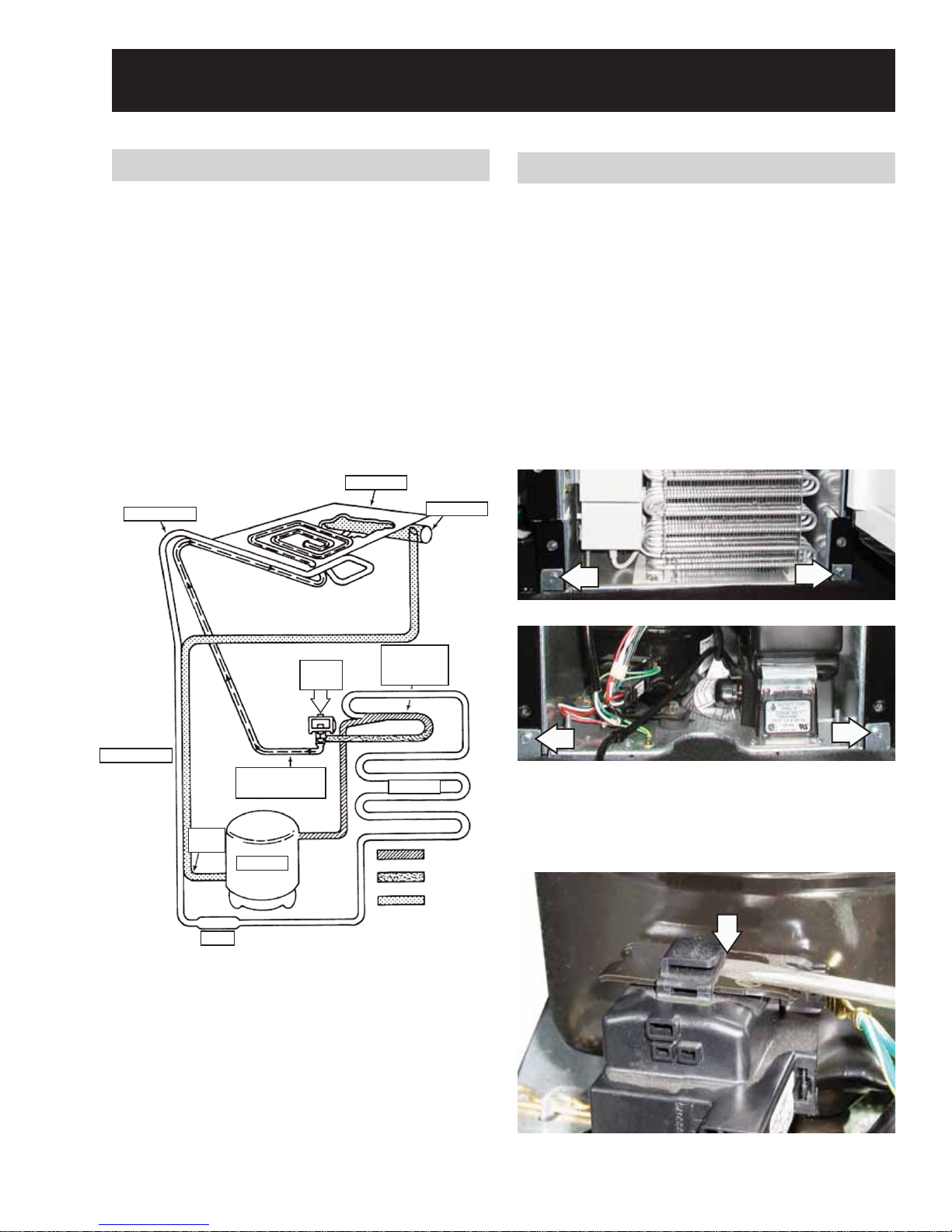
Refrigeration System
The refrigeration system is very similar to the
system used in other refrigeration appliances. The
refrigerant used in this unit is R134a.
There are 2 very important additions to the
refrigeration system in this Icemaker: the hot gas
valve and the condenser accumulator tube.
The 1. hot gas valve allows high pressure
refrigerant gas to bypass the condenser and
fl ow through the condenser accumulator tube.
Hot gas pushes liquid refrigerant through 2.
the condenser accumulator tube into
the evaporator, helping to evenly heat the
evaporator plate so that the ice slab releases
quickly and evenly.
Evaporator
Capillary Tube
Heat Exchanger
Hot Gas
Valve
Path of warm liquid refriger-
ant pushed by high-pres-
sure refrigerant gas
Accumulator
Condenser
Accumulating
Tube
Condenser
Suction
Tube
Drier
Compressor
– 7 –
High-Pressure
Refrigerant Gas
Warm Liquid
Refrigerant
Low-Pressure
Refrigerant Gas
(Continued next page)
Page 8

Water System
The water system provides:
Fresh water for ice production•
Water recirculation as ice is produced•
Water removal after ice is produced•
The water system circulates water on the
evaporator to freeze into ice during the freeze cycle.
During the harvest cycle, it drains away minerals
and contaminates. During the clean cycle, cleaning
Water System Component Locations
Evaporator
solution is circulated to clean the system of minerals
and contaminates.
The hardness of the water supplied to the icemaker
will affect the quality of the ice that is produced. It
may also affect the operation of the water system.
A water softener, or poly-phosphate feeder, will not
cure all of the problems associated with hard water,
but they can be used to reduce scale buildup in the
icemaker.
Water Distributor
Water Return Tube
Water Valve Outlet Tube
Measured Fill
Water Inlet Valve
From Water Supply
Manual Drain
Drain Overfl ow
– 8 –
Water Level Sensor
Water Recirculation Pump
Reservoir Pan
Reservoir Drain Pan
Bin Drain
(Continued next page)
Page 9

Operational Modes
There are 4 main operational modes for the
icemaker:
Ice-making cycle (Freeze Mode) 1.
Harvest2.
Clean3.
Service (Diagnostics)4.
Ice-Making Cycle (Freeze Mode)
There are 3 possible “Off” cycles for the icemaker.
They occur when:
The bin is full of ice and the ON LED is 1.
illuminated (Idle Mode).
The OFF control pad has been held for 3 sec. 2.
(The ON LED will go out.)
The power is interrupted by overfi ll. (Model ZPK1 3.
only with internal drain pump.)
Electrical System: Line voltage is supplied to
the electrical control switches and the primary
side of the step-down dual transformer. The dual
transformer reduces 120 VAC to 8.75 VAC for the
cutter grid and the bin light, and 12 VAC for the
drain and recirculating pumps.
The electronic control board directs 12 VAC to the
water recirculating and reservoir drain pumps, and
120 VAC to the hot gas solenoid, condenser fan
motor, and compressor.
During the later stages of the freeze mode, an ice
slab forms on the evaporator freezing plate. This
ice slab causes some of the refrigerant passing
through the evaporator to not evaporate into a
gas, but remain a liquid. This liquid refrigerant
settles in the accumulator. The refrigerant vapor is
sucked off through the suction tube at the top of the
accumulator.
This accumulated liquid refrigerant will eventually
be directed to the evaporator to quickly warm the
evaporator plate during the harvest mode.
Caution: It is very important that the accumulator
is not tilted out of a horizontal position. If moved, it
could cause compressor failure.
Water System: The water recirculation pump
moves the water from the reservoir pan up to the
distributor. The water fl ows out over the evaporator
freezing plate. Water that does not freeze on the
evaporator plate runs off the front edge. It falls back
into the reservoir, where it is recirculated back to the
water distributor.
As the ice slab forms, the minerals in the water are
on the surface of the ice. The water fl owing over
the top of the ice slab washes these minerals back
into the water reservoir pan. The water continues to
recirculate until the water level in the reservoir drops
below a level determined by the water level sensor.
At this point, the control terminates the freeze mode
and initiates the harvest mode.
The measured fi ll water inlet valve will always
have 120 VAC on the black and white wires and
14 VDC on the orange/white and black/red wires.
An evaporator thermistor supplies temperature
information to the electronic control to determine
when to terminate the harvest cycle. A water level
sensor initiates the next harvest.
Refrigeration System: The hot gas refrigerant,
under high pressure, is forced through the
condenser, where it changes into a liquid and
fl ows through the drier and capillary tube into the
evaporator. Under low pressure in the evaporator,
the liquid refrigerant absorbs heat from the
water fl owing over the evaporator and the liquid
refrigerant changes to gas. As a low-pressure gas,
the refrigerant fl ows back through the suction line of
the heat exchanger to the compressor.
During the freeze mode, some of the hot gas that is
in the condenser accumulating tube condenses to a
liquid and remains in the accumulating tube.
– 9 –
(Continued next page)
Page 10

Harvest Mode
Electrical System: When the water level in the
reservoir drops below the water level sensor, it
signals the electronic control to terminate power to
the condenser fan, and then the water recirculating
pump. The reservoir drain pump is activated (on for
20 sec., off 20 sec., back on for 20 sec.), to fully drain
the reservoir. Power is then supplied to the hot gas
valve and a fi ll request is sent to the measured fi ll
water inlet valve. The fi ll valve fi lls to the requested
volume while the hot gas valve is energized for
the balance of the harvest mode. If the evaporator
thermistor is unplugged, the evaporator defaults to
a timed 4-minute harvest.
If the water level sensor is disconnected or open, the
control defaults to 25 minutes of freeze time. The
cleaning indicator LED feature will not function if the
water level sensor is disconnected.
Refrigeration System: The hot gas valve opens,
allowing high-pressure refrigerant gas to bypass
the condenser, and fl ow through the condenser
accumulating tube. The hot gas pushes the
liquid refrigerant that has accumulated in the
accumulator tube up into the evaporator. The hot
liquid refrigerant evenly heats the evaporator plate
so that the ice slab releases quickly and evenly.
Water System: The reservoir drain pump is
activated (on for 20 sec., off 20 sec., back on for 20
sec.) to fully drain the reservoir. When fully drained,
the electronic control board sends a signal to the
water valve. The signal tells the measured fi ll water
inlet valve how much water is to be fi lled, allowing
water to fl ow into the water reservoir pan. The water
fi ll volume is determined by the ice thickness setting.
Thin Ice uses 32oz (954cc), Normal Ice uses 37oz
(1106cc) and Thick Ice uses 42.5oz (1258cc).
Note: Two minute maximum fi ll. The cycling
between freeze and harvest continues until the ice
bin is full. The electronic control board operates the
various components and systems in the icemaker
for each of the freeze and harvest modes.
Clean Mode (CLEAN LED on Amber, then Red)
The CLEAN LED turns from green to amber, then to
red. The CLEAN LED will turn from green to amber
after 50 hung slabs* or 3500 freeze cycles. The
CLEAN LED will then turn to red after 70 hung slabs*
or 4000 freeze cycles.
With the CLEAN LED on red and steady, the unit
must be cleaned to turn it off. When the clean cycle
is complete (approximately 70 minutes), the CLEAN
LED will be green and the OFF LED will be red.
The ice slab, when released, slides off of the
evaporator plate onto the cutter grid.
As a result of the hot gas fl ow and the ice sliding off
the evaporator plate, the evaporator temperature
begins to rise. When the evaporator thermistor
reaches the set temperature (52°F), the unit switches
to the Freeze Mode.
Select and hold the OFF pad for 3 seconds to turn
the unit off. Then press the ON pad to turn the unit
on. Customer instructions for Clean Cycle are on the
inside of the door.
*Hung Slab: If the time between the start of a freeze cycle
and the start of the harvest cycle is less than fi ve minutes, the
control will count a hung slab.
– 10 –
(Continued next page)
Page 11

Electrical System: The electronic control board
operates the various components and systems
during the clean mode. The clean mode may only
be selected while the icemaker is turned off (OFF
button held 3 sec.) at the user interface.
When the clean mode begins, the clean light fl ashes
1 sec. on then 1 sec. off. The circulation pump,
compressor, and hot gas valve are energized for
40 min.
The measured fi ll water inlet valve is energized
for 3 minutes, and then the recirculation pump is
energized for 3 minutes. This process is repeated 5
times for a total of 30 minutes.
The electrical control board turns all components
off. The CLEAN LED remains on with reservoir full.
Refrigeration System: The compressor and hot
gas valve operate to heat the evaporator. The
evaporator thermistor will cycle the compressor off
at 125°F and on at 95°F.
Water System: When the icemaker is in the CLEAN
mode, the water recirculating pump circulates
the cleaning solution that has been added to the
reservoir up to the water distributor, across the
evaporator, and back into the reservoir, where it is
recirculated.
Note: Do not continue with the diagnosis of the ice
maker if a fuse is blown, a circuit breaker is tripped,
or if there is less than a 120-Volt power supply at
the wall outlet. All units that have failed during the
fi rst few days of use should be checked for loose
connections or miswiring.
– 11 –
Page 12
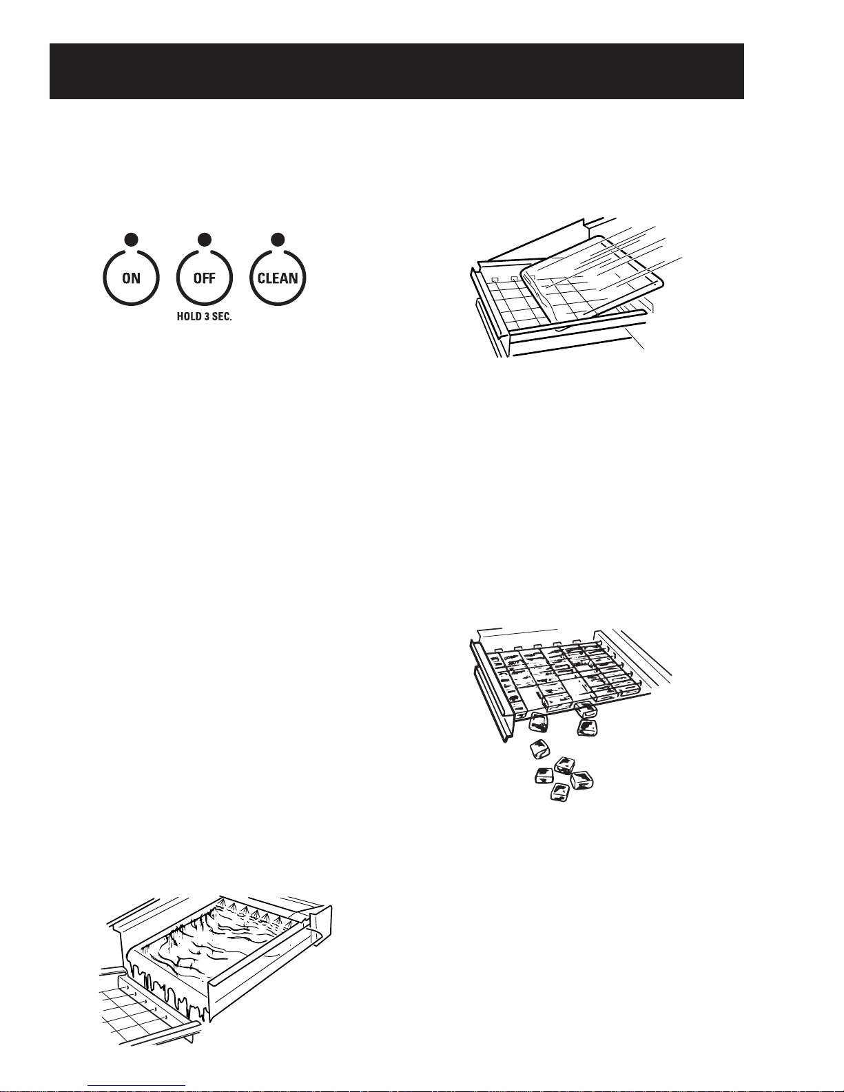
Control Features
User Controls
To start the normal ice making cycle, select 1. ON.
To stop icemaker operation, press and hold 2. OFF.
Note: The CLEAN setting is used whenever solutions
are circulated through the icemaker for cleaning.
How the Icemaker Works
When you fi rst start your icemaker, the water
reservoir will fi ll and the system will rinse itself
before starting to make ice. The rinsing process
takes about 5 min.
Under normal operating conditions, the icemaker
will cycle on and off as needed. The ice level sensor
located in the ice storage bin will monitor the ice
levels.
Notes:
When the desired thickness is reached, the ice 2.
sheet is released and slides onto a cutter grid.
The grid divides the sheet into individual cubes.
The water containing the rejected minerals is 3.
drained after each freezing cycle.
Fresh water enters the machine for the next ice-4.
making cycle.
Cubes fall into the storage bin. When the bin 5.
is full, the icemaker shuts off automatically
and restarts when more ice is needed. The ice
bin is not refrigerated and some melting will
occur. The amount of melting varies with room
temperature.
If the water supply to the icemaker is turned off, •
be sure to set the icemaker control to OFF. Drain
the water reservoir and leave the icemaker door
open to allow it to dry completely.
The icemaker is designed to make clear ice from •
the majority of water sources on a daily basis. If
your results are unsatisfactory, your water may
need to be fi ltered or treated.
Making Ice
Water is constantly circulated over a freezing 1.
plate. As the water freezes into ice, the minerals
in the water are rejected. This produces a clear
sheet of ice with a low mineral content.
Note: As the room and water temperatures vary,
so will the amount of ice produced and stored. This
means that higher operating temperatures result in
reduced ice production.
– 12 –
(Continued next page)
Page 13

Care and Cleaning
Caring for the Icemaker
The CLEAN light signal will illuminate yellow when
the electronic control senses that the need for
cleaning is approaching. At this time you need to
purchase
nickel-safe ice machine cleaner
by
Nu-Calgon, available at most appliance repair shops
or through GE Parts and Accessories. Order part
number WX08X42870. In the U.S.A., call 1-800-626-
2002 or visit Monogram.com. In Canada call 1-800-
561-3344. The CLEAN light will eventually turn
red which means the icemaker must be cleaned,
otherwise ice production will decrease signifi cantly
or stop altogether.
IMPORTANT: For best results, use the entire contents
of the bottle to clean the unit. (See Icemaker System.)
The air-cooled condenser needs to be cleaned
regularly for effi cient ice production and energy
conservation.(See Cleaning the Condenser.)
Exterior surfaces
Door handles and trim―Clean with a cloth
dampened with soapy water. Dry with a soft cloth.
Keep the outside clean. Wipe with a clean cloth
lightly dampened with mild liquid dish detergent.
Dry with a clean, soft cloth. Do not wipe the
icemaker with a soiled dish cloth or wet towel. These
may leave a residue that can damage the fi nish.
Do not use scouring pads, powdered cleaners,
bleach or cleaners containing bleach because these
products can scratch and damage the fi nish.
Press and hold the 1. OFF button for 3 seconds.
Wait 5 to 10 minutes for the ice to fall into the 2.
storage bin. Remove all ice from the storage bin.
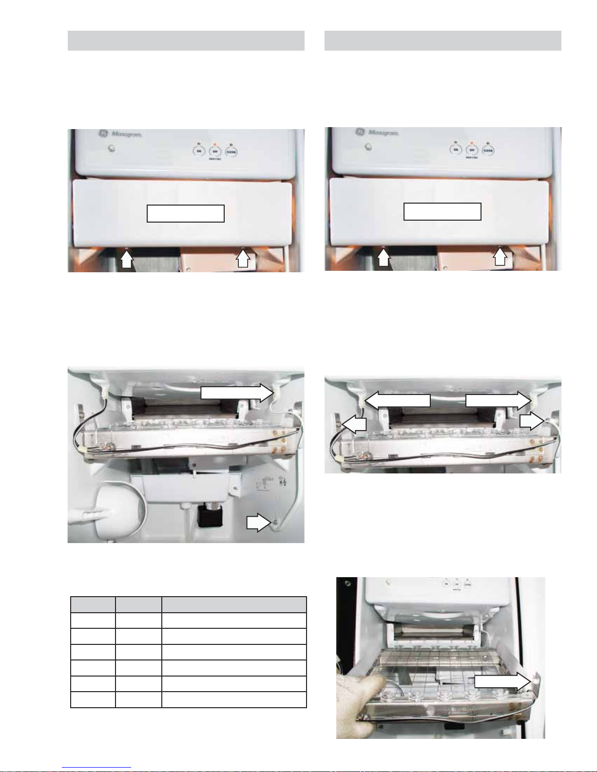
Unscrew the drain cap from the bottom of the 3.
water reservoir located inside the storage bin as
shown. Allow the water to drain completely.
Drain cap
Water reservoir
Replace the drain cap.4.
For best results, use the entire 16 oz. bottle of 5.
nickel-safe ice machine cleaner
. Follow all
safety precautions on the bottle. Pour one bottle
of solution into the water reservoir. Fill the bottle
twice with tap water and pour it into the water
reservoir.
Press and hold the CLEAN button for 3 sec. The 6.
CLEAN light will begin to blink, indicating that
the cleaning cycle is in process. The cleaning
time is approximately 70 min.
Stainless steel―Regularly clean and polish the
stainless steel door panels and handles (on some
models) with a commercially available stainless
steel cleaner such as Stainless Steel Magic™
to preserve and protect the fi ne fi nish. Stainless
Steel Magic is available through GE Parts and
Accessories, 800.626.2002, or monogram.com.
Order part number WX10X15. Do not use appliance
wax or polish on the stainless steel.
Icemaker System
Note: To remove stubborn buildup, pour a small
amount of cleaning solution on a non-scratching,
blue Scotch-Brite™ pad. Using only front-to-back
motions, clean the top of the plate, the sidewalls,
and the front edge of the evaporator. The frontto-back motion is important to avoid scratches
that could keep the ice slab from sliding off the
evaporator plate.
– 13 –
When the indicator light becomes solid and 7.
remains lit, the cleaning cycle is complete.
During the cleaning cycle, the system will both
clean and rinse itself.
After the cleaning cycle is complete, remove 8.
the drain cap from the water reservoir to see
if any cleaning solution, green in color, is left in
the water reservoir. If cleaning solution drains
from the water reservoir, you should run the
clean cycle again adding only tap water to
the reservoir. Be sure to replace the drain cap
before running the cycle again. If the cap is not
securely tightened, water can leak, causing thin
ice or no ice.
(Continued next page)
Page 14

Note: Severe scale buildup may require repeated
cleaning with a fresh quantity of cleaning solution.
Press the 9. ON button for 3 sec. to resume ice
production.
Cleaning the Condenser
For best performance, brush or vacuum lint and dirt
from the condenser at least once a year. A dirty or
clogged condenser:
Uses more energy.•
Reverse-Osmosis System
IMPORTANT: The performance of the icemaker may
be affected when connected to a reverse-osmosis
system. An RO system may also reduce water
pressure and affect the fi ll cycle, which is dependent
on time and fl ow. The reduced water pressure may
cause the reservoir not to fi ll and fl ush properly
during the ice-making cycle. The pressure of the
water supply coming out of a reverse-osmosis
system going to the measured fi ll water inlet valve
of the icemaker needs to be between 30 and 120 psi.
Prevents proper airfl ow.•
Reduces ice-making capacity.•
Causes higher-than-recommended operating •
temperatures, which may lead to component
failure.
Unplug the icemaker or disconnect power.1.
Remove the 2 screws in the lower access panel 2.
and the 2 screws from the base grille area of the
front panel support. Pull forward to remove the
lower access panel.
Pull the bottom forward and then pull down to 3.
remove the lower access panel.
If a reverse-osmosis water fi ltration system is
connected to your cold water supply, the water
pressure to the reverse-osmosis system needs
to be a minimum of 40 psi. The reverse-osmosis
system must provide 1 gal. of water per hour to the
icemaker for proper icemaker operation.
Note: Do not use copper tubing when the icemaker
is connected to a reverse-osmosis water system.
Remove dirt and lint from the condenser 4.
fi ns and the unit compartment with a brush
attachment attached to a vacuum cleaner.
Replace the lower access panel using the 4 5.
screws.
Plug in the icemaker or reconnect power.6.
– 14 –
Page 15

Problem Solving Chart
PROBLEM POSSIBLE CAUSE
CLEAN INDICATOR
LIGHT ON CONTROL
PANEL IS YELLOW
CLEAN INDICATOR
LIGHT ON CONTROL
PANEL IS RED
ICEMAKER DOES
NOT OPERATE
ICE CUBES
HAVE ODOR/TASTE
ICEMAKER IS ON,
BUT DOESN’T
PRODUCE ICE
ICEMAKER IS ON,
BUT PRODUCES
LITTLE OR NO ICE
ICEMAKER PUMPS
CONTINUOUSLY,
BUT PRODUCES
NO ICE
ICE IS THIN, SOFT
OR CLUMPED
ICEMAKER SOUNDS
• It will soon be time to clean the icemaker. You will need WX08X42870 Nickel Safe
Ice Machine Cleaner to clean the icemaker.
See Care and Cleaning–Care for your Icemaker.
• It is time to clean the icemaker. See Care and Cleaning–Icemaker System section.
• Power cord is not plugged into a live outlet.
• The control is set at OFF.
• The fuse is blown/circuit breaker is tripped. Replace fuse or reset the breaker.
• ZPK1 Auxiliary Kit fault.
• Drain line kinked or blocked.
• High mineral content in the water supply. Water may need to be filtered or treated.
• Food items stored in ice bin. Do not store any foods in the ice bin.
• Packaging materials were not removed. Make sure that all packaging materials
were removed at the time of installation.
• Ice storage bin needs cleaning.
• Scale has built up in the icemaker. If there is white scale buildup in the icemaker’s
water or freezing system, you should clean the icemaker.
See Care and Cleaning—Icemaker System.
• The control is set at OFF.
• Water supply is turned off or not connected.
• Condenser is dirty. Dirt or lint may be blocking the airflow through the condenser.
See Care and Cleaning—Condenser.
• Scale has built up in the icemaker. If there is white scale buildup in the icemaker’s
water or freezing system, you should clean the icemaker.
See Care and Cleaning—Icemaker System.
• Check for a kink in the drain hose from the ZPK1 Drain Pump Kit to the house drain.
• Water supply has been interrupted.
• Have a plumber check for a clogged water valve.
• Room temperature is colder than normal. Room temperature must be above
55˚F (13˚C). Otherwise, bin thermostat may sense cold room temperature
and shut off even though the bin is not full of ice. Also, unit may not restart once
it does shut off.
• Condenser is dirty. Dirt or lint may be blocking the airflow through the condenser.
See Care and Cleaning—Condenser.
• Scale has built up in the icemaker. If there is white scale buildup in the icemaker’s
water or freezing system, you should clean the icemaker.
See Care and Cleaning—Icemaker System.
• Water is leaking from the water reservoir because the drain cap is not secure.
Make sure the drain cap is securely tightened. Refer to illustration in
Care and Cleaning—Icemaker System section.
• Room temperature is too hot. Room temperatures of more than 90˚F (32˚C)
will reduce ice production.
•
The ice sheet is trapped on the cutter grid. Shut off the icemaker for at least one
hour to allow the ice sheet to melt. Turn the icemaker back on. The icemaker will
reset itself and start a new cycle after flushing water through the system. NOTE:
Follow the directions in the Care and Cleaning—Icemaker System section to clean
with the Nickel Safe Ice Machine Cleaner.
• High mineral content in the water supply. Water may need to be filtered or treated.
• Scale has built up in the icemaker. Clean your icemaker.
See Care and Cleaning—Icemaker System section.
• The ice bin is not refrigerated, so ice not regularly used will melt and form clumps.
Break the clumps with the ice scoop provided.
• After an ice-making cycle, you may hear ice cubes dropping into the storage bin.
• Water is circulated by a pump through the icemaker during the entire ice making
-
cycle. Water is added once per ice-making cycle.
• The compressor may cause a clicking or chirping sound when attempting
to restart.
• The flow of refrigerant through the refrigerating system may make a gurgling
sound like boiling water.
• A “whooshing” sound may indicate the water supply is not connected properly,
the water supply is turned off or the drain cap is loose.
– 15 –
(Continued next page)
Page 16

Evaporator*
Cutter Grid
Compressor
Dual Transformer
Component Locator
Electronic
Light Switch
Control Board
Push-button
Switch
Bin Thermistor
Water Level
Sensor
Water Recirculation
Pump
Reservoir
Drain Pump
Condenser Fan Motor
Hot Gas Valve & Solenoid
(Behind Condenser)
Measured F1 Water Valve
* The evaporator thermistor is located on
tubing below the evaporator.
Condenser
Condenser Accumulator Tube
– 16 –
(Continued next page)
Page 17

Water System Component Locations
Evaporator
Water Distributor
Water Return Tube
Water Valve Outlet Tube
Measured Fill
Water Inlet Valve
From Water Supply
Manual Drain
Drain Overfl ow
Water Level Sensor
Water Recirculation Pump
Reservoir Pan
Reservoir Drain Pan
Bin Drain
– 17 –
Page 18
Components
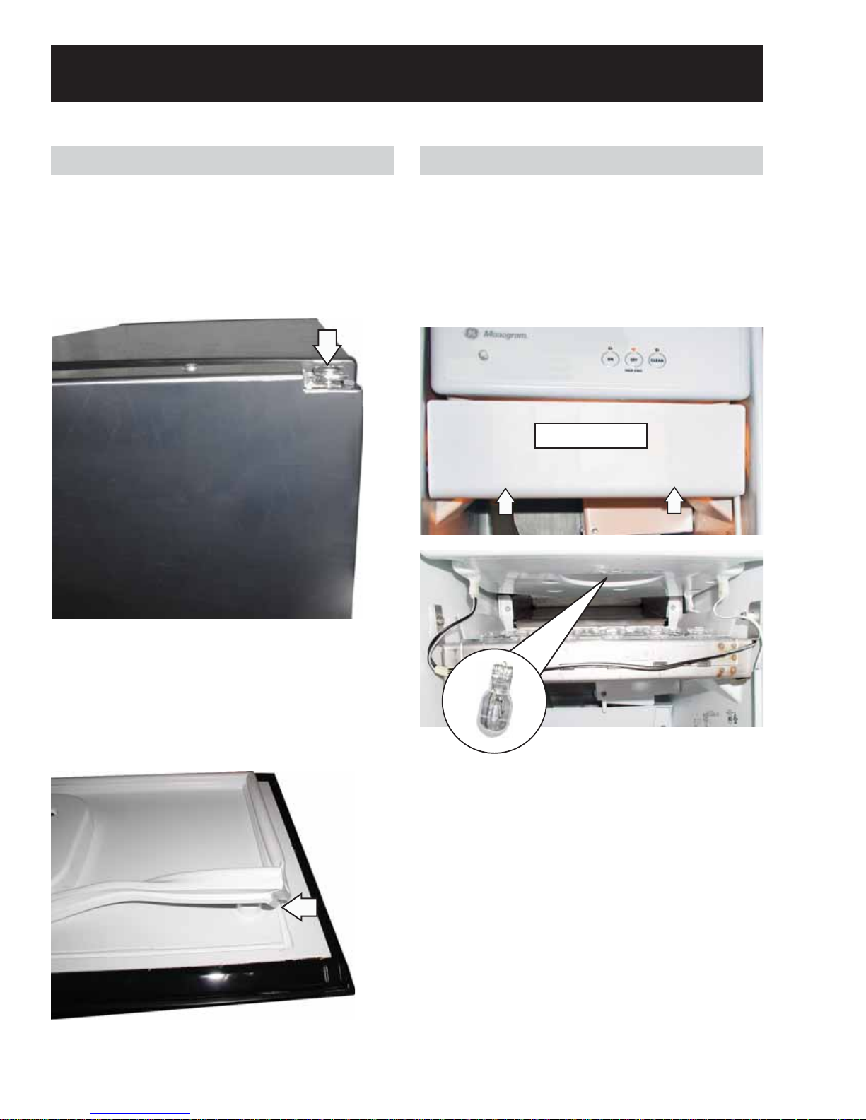
Door and Gasket
Note: If unit has a handle attached to the top of the
door it must be removed to access the hinge screw.
To remove the door, remove the large screw from
the top of the icemaker door, pull the door open, and
lift the door off the bottom hinge.
Bin Light Bulb
Remove two 1/4-in. hex-head screws from the
bottom of the cutter grid cover and pull the cover
from the ice machine.
Reach in and above the cutter grid to the depression
in the bottom of the control assembly. Grasp the
bulb and pull straight down.
Cutter Grid Cover
Note: Be sure to check the new gasket for a proper
seal after it is installed.
To remove the door gasket, open the icemaker door
and pull the gasket out of the door track.
The bulb is a #917 auto type (12V) and can be
purchased locally.
– 18 –
Page 19
Bin Thermistor
Cutter Grid
To remove the bin thermistor:
Remove two 1/4-in. hex-head screws from the
bottom of the cutter grid cover and pull the cover
from the ice machine.
Cutter Grid Cover
Disconnect the thermistor plug from the bottom of
the control panel.
Remove the hex-head screw and clamp securing
the thermistor to the side wall and remove
thermistor.
To remove the cutter grid:
Remove two 1/4-in. hex-head screws from the 1.
bottom of the cutter grid cover and pull the
cover from the ice machine.
Cutter Grid Cover
Disconnect the cutter grid and bin thermistor 2.
connectors from the bottom of the control
housing.
Remove the 2 hex-head screws from both sides 3.
of the cutter grid, (Note that the longer screw
and white spacer are on the right side.)
Thermistor Plug
The bin thermistor should read 12.49 KΩ at room
temperature.
°F °C Thermistor Resistance
0 -18 81,715 - 99,874 Ω
10 -12 59,422 - 72,627 Ω
32 0 30,266 - 36,992 Ω
50 10 18,219 - 22,267 Ω
70 21 10,280 - 12,564 Ω
90 32 6,387 - 7,807 Ω
Disconnect
Disconnect
Note: Take care not to scratch the icemaker liner.
Slide the cutter grid forward and out of the unit 4.
and place it on a protected work surface.
Remove the spacer from the right cutter grid 5.
bracket tab.
Spacer
– 19 –
(Continued next page)
Page 20

Unsnap the 2 ice guides, if necessary, from 6.
the cutter grid tabs. (There should be a slight
outward tilt after the guides are installed.)
Evaporator Thermistor
To remove the evaporator thermistor:
Remove the cutter grid. (See 1.
Cutter Grid.)
Disconnect the evaporator thermistor from the 2.
bottom of the control housing.
Ice Guide
Ice Guide
Remove the 2 hex-head screws from the water 3.
trough and pull the trough from the unit.
Disconnect
Bend the metal tabs outward, if necessary.7.
Reach behind the accumulator, and unclip the 4.
evaporator thermistor.
When installing, snap the thermistor onto the 5.
evaporator tubing behind the accumulator.
Water Distributor
Remove the cutter grid from the unit. See (1. Cutter
Grid.)
Pull out on the left and right water distributor 2.
retainers, and remove the tabs from the slots in
the evaporator.
Pull the distributor forward and remove the 3.
water hose.
Water Hose
– 20 –
Page 21

Electronic Control Housing Components
Note: The control housing components consist of:
Electronic control board•
Dual transformer•
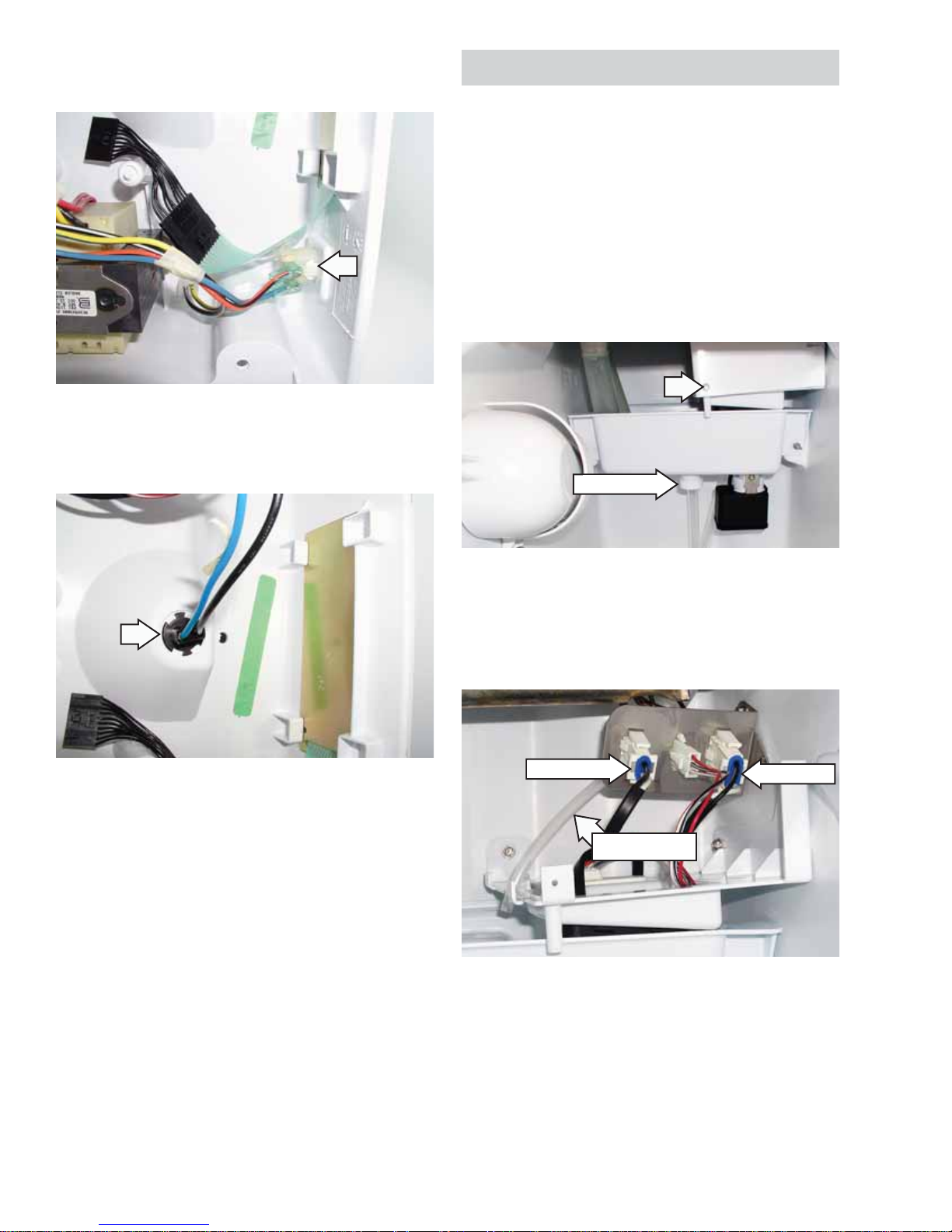
To Remove the Dual Transformer
Disconnect the 6-pin wire connector from the 1.
harness.
Remove the 2 mounting screws from the 2.
transformer bracket.
Light switch•
Push-button switch assembly•
Remove the cutter grid cover and the cutter 1.
grid. (See
Cutter Grid.)
Disconnect the 2 thermistor connectors. (See 2.
Thermistor and Evaporator Thermistor.)
Remove the 4 hex-head screws from the control 3.
housing and lower the housing to access the
components.
Disconnect the green ground wire from its 3.
terminal.
Bin
Transformer
2nd screw on opposite side
To Remove the Light Switch/Push-Button
Assembly
Note: If the switch assembly or light switch is
replaced, the replacement part and decorative
overlay must be ordered using the model number of
the icemaker. The service replacement switch is not
supplied with a decorative overlay
To Remove the Electronic Control Board
Disconnect the 6 harness connectors from the 1.
board terminals.
Remove the 2 mounting screws and remove the 2.
electronic control board.
Peel off the decorative overlay from the front of 1.
the control housing.
– 21 –
(Continued next page)
Page 22
Disconnect the Molex plug from switch 2.
assembly.
Press the back of switch assembly and push the 3.
switch assembly out of the housing.
Water Recirculation Pump
Remove the ice from the storage bin prior to
removing the recirculation pump.
Note: Pump operates on 12 VAC and has a
resistance of 3.8Ω.
To remove the water recirculation pump:
Unscrew the drain cap from the reservoir, drain 1.
the water, and replace the cap tightly.
Remove the hex-head screw from the water 2.
recirculation pump shield and remove the shield.
Drain Cap
Disconnect the water fi ll tube from the pump 3.
mounting bracket.
Disconnect the wire recirculation and drain 4.
pump connectors from the harness block.
Disconnect
Water Fill Tube
Disconnect
– 22 –
(Continued next page)
Page 23
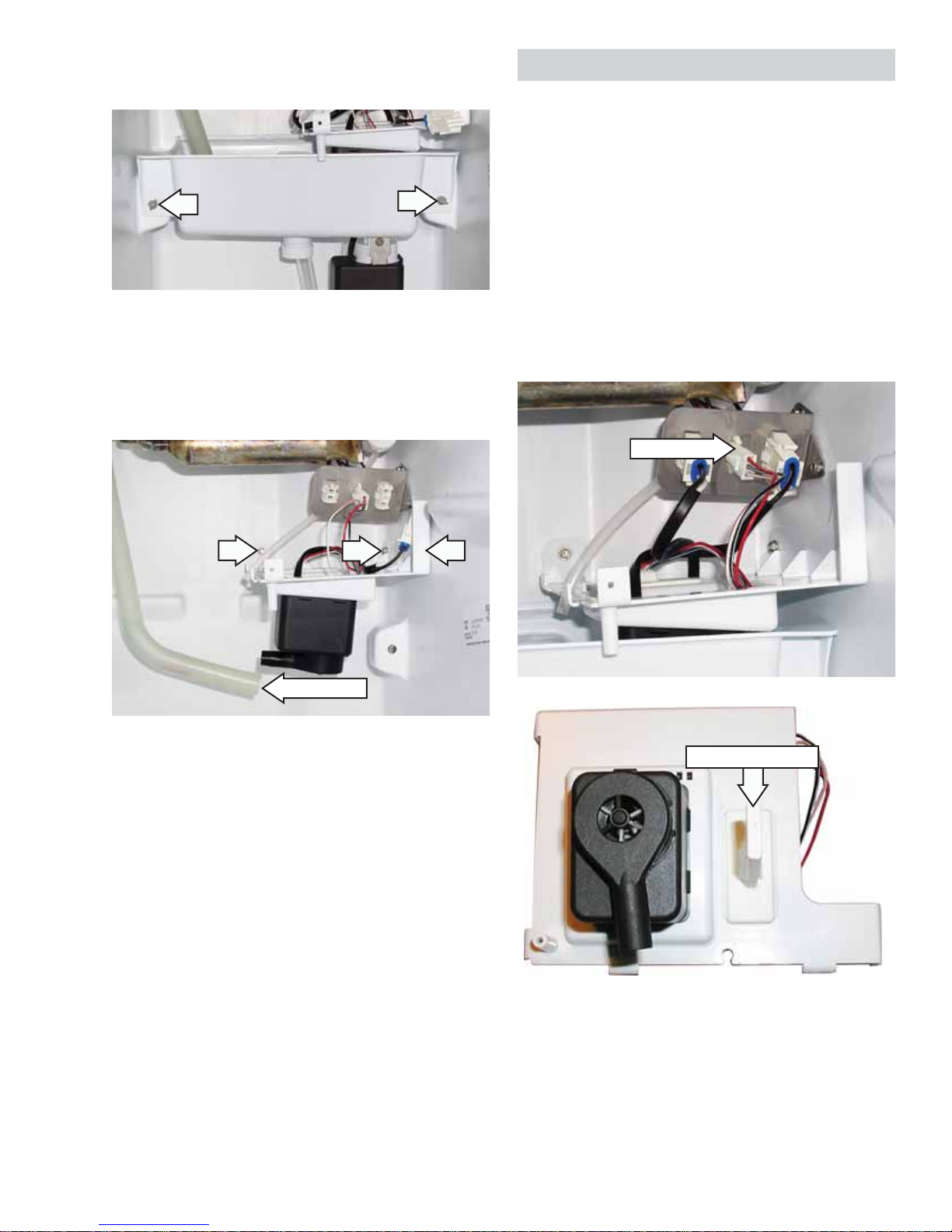
Remove the 2 thumbscrews from the reservoir 5.
and remove the reservoir from the icemaker.
Remove the recirculation pump outlet tube.6.
Remove 3 hex-head screws from the pump 7.
mounting bracket and remove the pump/water
level sensor assembly.
Water Level Sensor
Remove the ice from the storage bin prior to
removing the recirculation pump.
To remove the water level sensor:
Remove the hex-head screw from the water 1.
recirculation pump shield and remove the shield.
(See
Water Recirculation Pump.)
Disconnect the water level sensor electrical 2.
connection.
Remove the retaining clips, if present.3.
Pull the sensor up and out of the bracket.4.
Disconnect
Outlet Tube
Water Level Sensor
– 23 –
Page 24

Reservoir Drain Pump
Condenser Fan Motor
Remove the ice from the storage bin prior to
removing the recirculation pump.
Note: Pump operates on 12VAC and has a
resistance of 3.8Ω.
To remove the reservoir drain pump:
Unscrew the drain cap from the reservoir, drain 1.
the water, and replace the cap tightly.
Remove the recirculating pump cover hex-head 2.
screw.
Drain Cap
To remove the condenser fan motor:
Disconnect the water and drain lines from 1.
the icemaker and remove the unit from its
installation.
Remove the 4 hex-head screws from the front 2.
panel and remove the panel.
Disconnect the reservoir drain pump electrical 3.
connection.
Remove the pump-retaining Phillips-head screw 4.
and bracket.
Rotate the pump 1/4 turn and pull it down and 5.
out of the reservoir.
Disconnect
Remove the two 5/16-in. screws from the front 3.
of the cabinet.
Remove 2 hex-head screws from the measured 4.
fi ll water valve bracket.
Allow the valve to drop down out of the way.5.
Measured Fill Water Valve
– 24 –
(Continued next page)
Page 25

From the back of the unit, remove the 4 hex-6.
head screws from the unit compartment cover
and remove the cover.
Tilt the front of the cabinet back until you can 9.
access the 2 side screws on the condenser fan
motor shroud, and secure the cabinet so that it
cannot tip forward or backward.
Disconnect the wire connector from the 10.
condenser fan motor.
Remove the 4 screws (2 bottom and 2 side) 11.
from the condenser fan motor shroud. Slide the
shroud assembly back towards the compressor,
and then lift and remove the assembly from the
unit.
Disconnect
Remove the two 5/16” screws from the rear of 7.
the cabinet.
Note: If the unit you are servicing is not equipped
with an internal drain pump, skip the next step.
Disconnect the inlet tube and the vent tube from 8.
the internal drain pump.
Vent Tube
Inlet Tube
Remove condenser fan motor blade by pulling 12.
the fan blade straight off the shaft.
Note: Make sure when reinstalling the fan blade
that the blade is seated completely on the motor
shaft.
Remove the 2 hex-head screws from the 13.
condenser fan motor and remove the motor
from the shroud.
– 25 –
Page 26

Measured Fill Water Valve
Hot Gas Solenoid
To remove the measured fi ll water valve:
Turn the water supply off to the icemaker.1.
Remove the 4 hex-head screws from the front 2.
panel and remove the panel.
Remove the 2 hex-head screws from the 3.
measured fi ll water valve bracket.
To remove the hot gas solenoid:
Tip the cabinet back and securely prop it up to 1.
access the hot gas valve solenoid.
Disconnect the 2-wire connector from the 2.
solenoid terminals.
Measured Fill Water Valve
Note: Place a pan or towel under the valve to catch
the water.
Disconnect the water inlet and outlets tubing 3.
from the quick-disconnect fi ttings on the
measured fi ll water valve.
Disconnect the 2 electrical connectors from the 4.
valve.
Outlet Tube
Inlet Tube
Disconnect
Remove the 7-mm hex-head screw from the 3.
solenoid and lift the solenoid off the hot gas
valve.
Disconnect
– 26 –
Page 27
Sealed System
Hot Gas Valve
To remove the hot gas valve:
Remove the solenoid from the hot gas valve. 1.
(See
Hot Gas Solenoid.)
Access the sealed system and discharge the 2.
refrigerant into an approved recovery system.
Unbraze the hot gas valve from the tubing.3.
Caution: When installing the new hot gas valve,
use a generous amount of thermal heat trap paste
between the valve and tubing joints to protect the
valve when brazing.
Evaporator
Capillary Tube
Accumulator
Compressor
To remove the compressor:
Unplug icemaker or disconnect power.1.
Open the icemaker door.2.
Remove the ice from the storage bin.3.
Disconnect the water and drain lines from 4.
the icemaker and remove the unit from its
installation.
At the front and rear of the unit, remove 5.
the 4 hex-head screws from the unit outer
compartment cover and remove the cover.
Heat Exchanger
Suction
Tube
Drier
Hot Gas
Path of warm liquid
refrigerant pushed by high-
pressure refrigerant gas
Compressor
Valve
Condenser
Accumulating
Tube
Condenser
High-Pressure
Refrigerant Gas
Warm Liquid
Refrigerant
Low-Pressure
Refrigerant Gas
To remove the terminal cover, use a fl at blade 6.
screwdriver. Insert the screwdriver under the clip
to unsnap and remove it.
– 27 –
(Continued next page)
Page 28
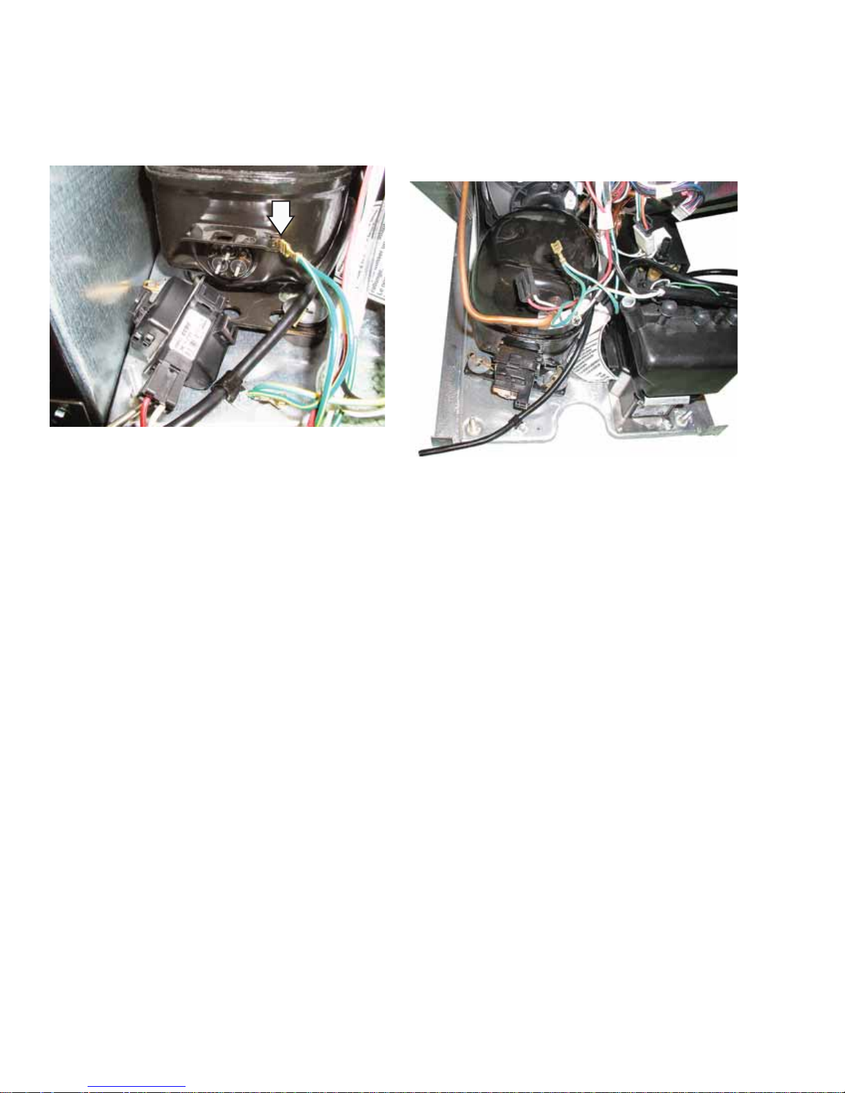
Remove the wires from the ground terminal, 7.
the overload protector terminal, and the relay
terminal.
Pull the overload protector and relay from the 8.
compressor pins.
Pull the clips off the compressor mounting studs.15.
Lift the compressor off the 4 mounting studs 16.
and remove it from the unit.
Remove the 4 metal spacers and rubber 17.
isolators from the compressor stud locations.
Pull the 2 clips off the rear studs of the 9.
compressor.
Tip the front of the cabinet back and prop it up.10.
Access the sealed system and discharge the 11.
refrigerant into an approved recovery system.
Cut the suction and discharge lines from the 12.
compressor.
Caution: Do not use a torch to remove the drier
fi lter.
Cut the drier fi lter from the system. 13.
Unbraze the compressor suction and discharge 14.
joints from the tubing.
– 28 –
Page 29
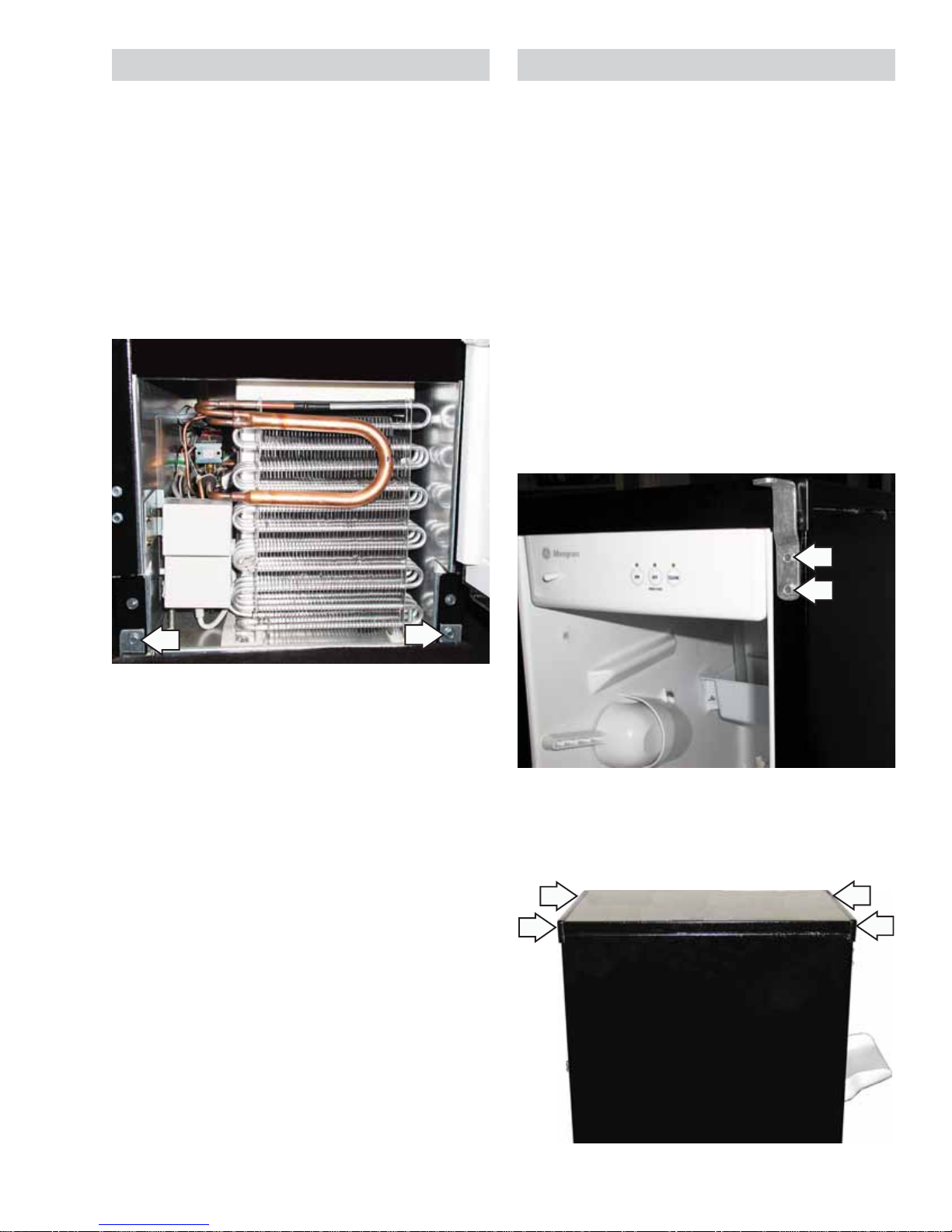
Condenser
Evaporator
To remove the condenser:
Unplug ice maker or disconnect power.1.
Tip the front of the cabinet back and prop it up.2.
Remove the 4 condenser fan motor screws from 3.
the fan motor shroud. Pull the motor assembly
back away from the condenser as far as
possible, but do not remove it.
Remove the 2 mounting screws from the 4.
condenser bracket fl anges.
To remove the condenser:
Unplug the ice maker or disconnect the power.1.
Note: If unit has handle attached to top of door it
must be removed to access hinge screw.
Remove the top door screw from the icemaker 2.
door, and pull the door off the bottom hinge.
Remove the ice from the storage bin.3.
Remove the cutter grid and the evaporator 4.
thermistor from the unit. (See
Cutter Grid and
Evaporator Thermistor.)
Disconnect the bin thermistor connector from 5.
the bottom of the control housing.
Remove the two 5/16-in. hex-head screws from 6.
the top hinge and remove the hinge.
Access the sealed system and discharge the 5.
refrigerant into an approved recovery system.
Unbraze the 2 condenser joints from the tubing.6.
Remove the 2 front and 2 rear screws from the 7.
cabinet top.
– 29 –
(Continued next page)
Page 30
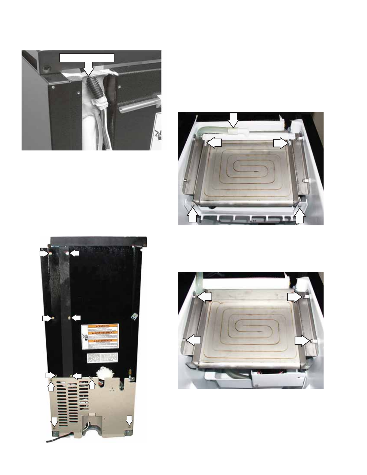
Lift the cabinet top and position it forward on 8.
top of the unit, and then remove the permagum
from around the electrical throughput.
Remove Permagum
Note: In the photo above, the rear channel cover has
been removed for clarity.
From the rear of the unit, remove the 6 hex-9.
head screws from the channel cover and
remove the cover.
Lift the cabinet top off the unit and stand it on 11.
the fl oor near the rear of the unit.
Remove the hex-head screw from the water 12.
recirculation pump shield and remove the shield.
Pull out on the left and right water distributor 13.
retainers and remove the tabs from the slots in
the evaporator.
Disconnect the hose from the water distributor 14.
and remove the water distributor.
Remove the 4 hex-head screws from the unit 10.
compartment cover and remove that cover.
Remove the 4 Phillips-head screws from the 14.
evaporator, and then carefully lift the evaporator
just high enough to remove the 2 right spacers.
– 30 –
(Continued next page)
Page 31
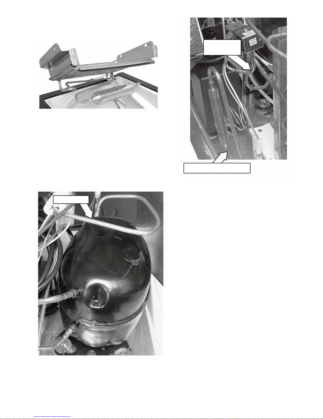
Lift the evaporator and its connecting tubing 15.
high enough from the unit to access the tubing
underneath.
Access the sealed system and discharge the 16.
refrigerant into an approved recovery system.
Unbraze (or cut) the evaporator from the tubing 17.
at the following locations:
Suction line at the compressor•
Hot Gas
Joint Valve
Hot gas line at the hot gas valve•
Cut the capillary tube at the drier fi lter•
Suction Line
Drier Filter Capillary Tube
– 31 –
Page 32

Component Testing
Before testing any of the components, perform the
following checks:
Control failure can be the result of corrosion •
on connectors. Therefore, disconnecting and
reconnecting wires will be necessary throughout
test procedures.
All tests/checks should be made with a VOM or •
DVM having a sensitivity of 20,000 Ω per volt DC,
or greater.
Check all connections before replacing •
components. Look for broken or loose wires,
failed terminals, or wires not pressed into
connectors far enough.
Resistance checks must be made with power •
cord unplugged from outlet, and with wiring
harness or connectors disconnected.
Bin and Evaporator Thermistors
Note: For the most accurate measurement,
immerse the thermistor in ice water for 5 minutes
and then use the 32°F/0°C reading in the chart
below.
Water Recirculation Pump and
Reservoir Drain Pump
Leads are 3.6 Ω at 12 VAC.
Condenser Fan Motor
Run the service mode. Check for the proper operation
of the condenser fan motor, 185 Ω at 120 VAC.
Water Level Sensor
Run the service mode. Check for the proper
operation of the water level sensor. The Service LED
should stay on solid when the water level sensor is
immersed in water. When the water level sensor is
out of the water, the Service LED should blink.
Hot Gas Valve Solenoid
Leads are 365 Ω to 390 Ω at 120 VAC.
Measured Fill Water Valve
Run the service mode. The connector with black and
white wires should read 120 VAC. The orange/white
wire to the black/red wire should read 14 VDC.
Compressor, Overload Protector, and Relay
°F °C Thermistor Resistance
0 -18 81,715 - 99,874 Ω
10 -12 59,422 - 72,627 Ω
32 0 30,266 - 36,992 Ω
50 10 18,219 - 22,267 Ω
70 21 10,280 - 12,564 Ω
90 32 6,387 - 7,807 Ω
Cutter Grid
Leads are 4 Ω to 5 Ω at 8.4 VAC
Dual Transformer
Primary black and white leads are 3.5 • Ω to 4.5 Ω
at 120 VAC.
Secondary yellow and yellow leads are 0.11 • Ω
to 0.14 Ω at 8.4 VAC.
Secondary red and red leads are 0.14 • Ω to 0.18
Ω at 12 VAC.
To test the compressor windings:
Common (C) pin to the Start (S) pin should read •
8 to 11 Ω.
Common (C) pin to the Run (M) pin should read 2 •
to 3 Ω.
To test the relay:
Position the relay with the coil facing down.1.
Insert the tip on one of the ohmmeter test leads 2.
into the Run (M) pin socket, and touch the other
ohmmeter lead to the spade terminal. The meter
should indicate a closed circuit (0 Ω).
Move the tip of the ohmmeter test lead from 3.
the spade terminal into the Start (S) pin socket.
Leave the other ohmmeter lead at the Run (M)
location. The meter should indicate an open
circuit (infi nite).
Turn the relay over so that the coil faces up.4.
With the tip of the ohmmeter test leads at the 5.
Start (S) and Run (M) pin sockets, the meter
should indicate a closed circuit (0 Ω).
– 32 –
(Continued next page)
Page 33
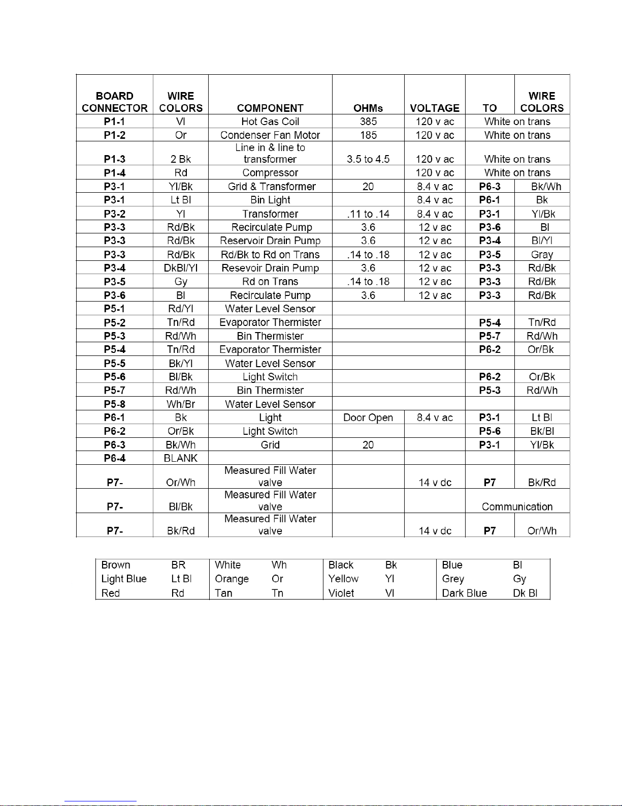
Board Connectors
See Page 40
See Page 32
See Page 32
See Page 32
See Page 40
See Page 32
See Page 40
– 33 –
(Continued next page)
Page 34

Component Connectors
See Page 32
See Page 32
See Page 40
See Page 40
See Page 40
– 34 –
Page 35

Control Board Diagnostics
Flush Mode: (Start-up Cycle) (6 minutes maximum)
The Flush Mode begins:
Every time the user plugs the icemaker in.•
The interface is changed from • OFF to ON.
When the icemaker is turned on after the •
completion of the CLEAN cycle, or
On auxiliary drain pump models only, power •
cycled off due to water touching the overfi ll
contact. This is often due to slow or blocked
drain, or a blocked vent hose.
When the power is applied or the icemaker is turned
ON at the user interface:
Water valve fi lls 45 oz. Maximum fi ll time is 2 •
minutes.
Recirculation pump runs for 1 minute.•
Reservoir drain pump is on for 20 sec., off for 20 •
sec., then on for 20 sec.
Water valve fi lls to the selected volume. •
Maximum fi ll time is 2 minutes.
Enter freeze mode•
Freeze Mode: (Ice-Making)
Note: If the water level drops below the sensor
before 5 minutes, the control counts a Hung Slab.
If the water level sensor is not detected, the control
sets a 25-minute freeze time.
Time in this mode is dependent on the water
level in the reservoir. There is no minimum time.
The maximum time is 25 minutes. Compressor,
condenser fan, and recirculation pump are all
energized.
Water continues to recirculate until the water level
in the reservoir drops below a level determined by
the water level sensor. At this point, the control
terminates the freeze mode and initiates the
Harvest Mode.
Harvest Mode
The time in this mode will be 2 to 17 minutes,
dependent on the condition of the evaporator
thermistor.
The compressor and hot gas valve is on for a
minimum of 1 minute.
Note: There is a 4-min. fi xed cycle time if the
evaporator thermistor is disconnected or open.
Harvest Mode: Bin Not Full
When the bin thermistor reads greater than 36°F:
Reservoir drain pump is on for 20 sec., off 20 •
sec., then back on for 20 sec.
Measured water fi ll is requested. Compressor •
and hot gas valve are on until: evaporator
thermistor reads greater than 52°F and more
than 1 minute, but less than 16 minutes have
passed; or after 4 minutes if the evaporator
thermistor is unplugged or open.
Harvest Mode: Bin Full
The time in this mode with the bin full will be a
minimum of 5 minutes. The mode continues as long
as the bin is full and the bin thermistor remains less
than 36°F.
Compressor and hot gas valve are on until the
evaporator thermistor is greater than 52°F and more
than 1 minute but less 16 minutes have passed;
or after 4 minutes if the evaporator thermistor is
unplugged or open.
Idle Mode:
Time in this mode is dependent on the temperature
at the bin thermistor.
Bin Not Full (Bin Thermistor Greater than 36°F)
The control sends a reservoir fi ll request and Freeze
Mode begins.
– 35 –
(Continued next page)
Page 36

Harvest Failure Mode:
If while in Harvest Mode, the evaporator thermistor
is less than 52°F and more than 16 minutes have
passed, Harvest Failure Mode will occur and the OFF
LED will fl ash 3 blinks. This mode will continue until
the failure is corrected.
OFF1. LED is fl ashing 3 blinks: Look for an
evaporator thermistor that has not reached
52°F. This may be due to an evaporator
thermistor being unplugged or open, a loose
or improperly positioned thermistor, a hot gas
failure, a sealed-system leak, or a restriction.
OFF2. LED is fl ashing 2 blinks: Look for a
disconnected or open bin thermistor.
Note: The bin thermistor is constantly checked
during the Flush Mode, the end of each Freeze
Mode, Harvest Modes, and Idle Mode.
Clean Mode:
Note: The customer instructions for clean cycle is on
the inside of door.
The Clean Mode may only be selected while the
icemaker is turned off (OFF pad held 3 sec.) at the
user interface.
Clean Mode is a 70-minute cycle:
When Clean Mode begins, The • CLEAN light
fl ashes 1 sec. on, 1 sec. off.
The circulation pump, compressor, and hot gas •
valve are energized for 40 minutes.
The water valve is energized for 3 minutes, and •
then the recirculation pump for 3 minutes. This
is repeated 5 times for total of 30 minutes.
All components off, • CLEAN LED remains on with
reservoir full.
Note: At the end of the Clean Mode, the icemaker
will stay off. CLEAN LED will be on green and OFF
LED on red. The reservoir is to be drained by the
consumer prior to restarting the icemaker. The
consumer must press OFF for 3 sec. before selecting
ON.
– 36 –
Page 37
Troubleshooting
,
oo
.
.
– 37 –
(Continued next page)
Page 38
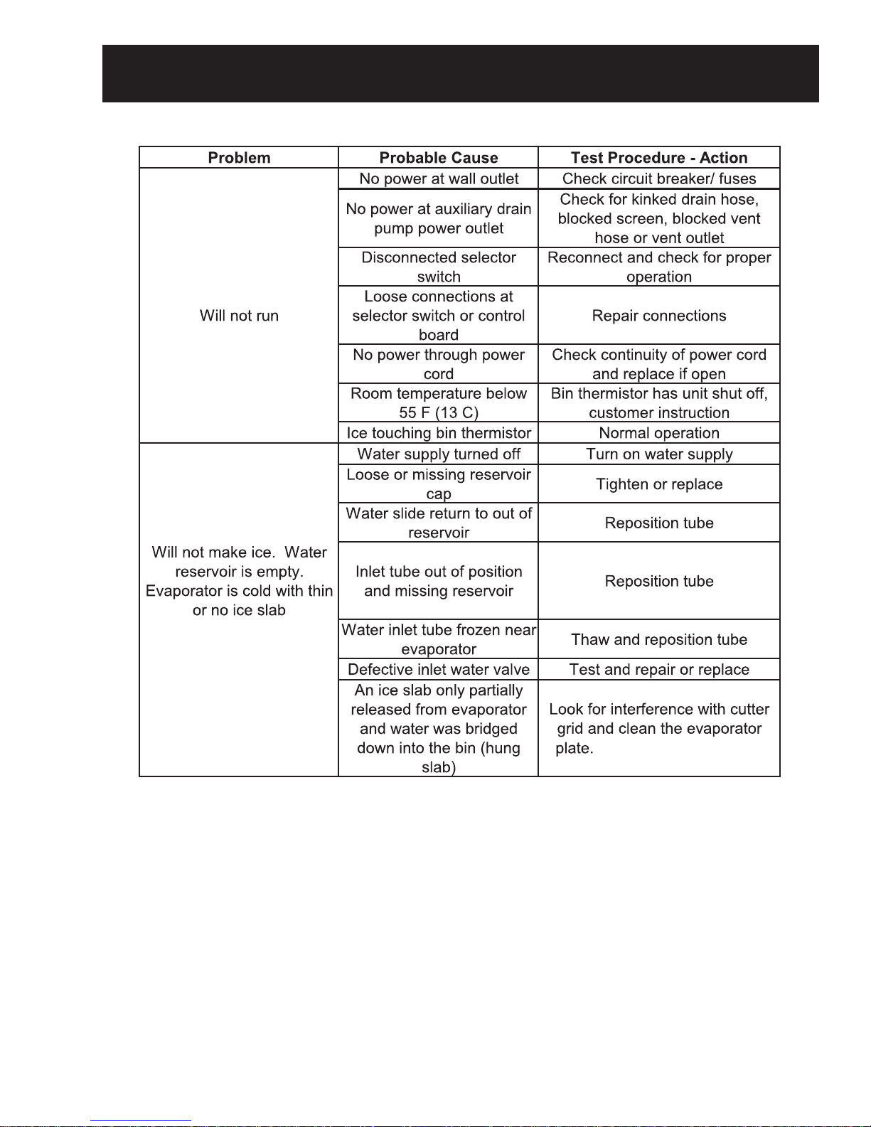
Problem Probable Cause Test Procedure - Action
Will not make ice. Water
reservoir is empty. Evaporator
is cold with 3/4 inch thick or
-
larger ice slab.
Will not make ice. Water
reservoir is full. Evaporator is
cold with thin, partial, irregular
or no ice slab.
Will not make ice. Water
reservoir is full. Evaporator is
warm.
Poor ice production.
Slab will not release during
harvest due to scale buildup
Defective or disconnected hot
gas valve
Clean evaporator plate; See
procedure on 4-21
Test and repair or replace
Defective hot gas valve Test and repair or replace
Room temperature over 100 F
o
(38 C)
Seeping water valve
condenser is hot
Partial refrigerant leak or
restriction (u-shaped slab)
Blocked condenser or stalled
fan motor
Tube not attached to outlet of
recirculating pump
Defective recirculating pump
Partially blocked water
distributor
Compressor is not running
Blocked condenser or stalled
fan motor
o
Customer instruction
Replace water valve
Check for leak/restriction and
repair or replace defective
component
Clean condenser, repair or replace
motor
Re-attach tube
Repair or replace the pump motor
assembly
Clean distributor and evaporator
Test compressor, relay and
overload
Clean condenser, repair or replace
motor
Unit is in the start-up mode Wait 5 minutes and re-check
Room temperature below 55 F
o
(13 C)
Seeping water valve
condenser is hot
Slow or defective drain or drain
pump causing water to back up
into the bin
o
Bin thermistor has unit shut off,
customer instruction
Replace water valve
Repair or replace drain or drain
pump
– 38 –
(Continued next page)
Page 39
Problem Probable Cause Test Procedure - Action
Too much ice in bin Defective bin thermistor Replace
The slab dropping off the plate
Banging sound
and ice dropping from the cutter
grid into an empty bin are normal
The reservoir is empty. Look for a
partially released slab,
Noisy Grinding, cavitating sound
interference with cutter grid, etc.,
and clean the evaporator plate.
See procedure on
Grinding, cavitating sound
If the reservoir is full, replace the
from recirculation pump
Noisy drain pump Repair or replace
Ice freezing together in the
bin
Normal
This is normal with low customer
sounds
4-21
pump
usage
Cloudy, poor tasting ice Poor water quality
Off LED flashing 2 blinks
-
Open or disconnected bin
thermistor or thermistor wiring
Defective, loose, or mis-
Off LED flashing 3 blinks
positioned evaporator
thermistor
See chart on
4-2 & 4-3
Test thermistor and wiring harness
or reconnect
Test thermistor and wiring harness
or reconnect
– 39 –
Page 40

Service Test Mode (Diagnostic Mode)
Note: Drain the reservoir before entering service
diagnostics, press the ON pad.
test mode.
Note: If no pad is pressed within 5 sec., the product
Turn the icemaker 1. ON.
goes into the automatic diagnostic mode used at
the assembly plant. Each component is cycled
Within 10 sec. of power on, press and hold the 2.
for 5 sec.
ON and the CLEAN pads. (Release both pads
when all user interface LEDs begin to fl ash.)
Within 5 sec. of all LEDs fl ashing, press and 3.
release the OFF pad.
Service Test Mode Chart
After pressing the OFF pad to enter manual
diagnostics, all LEDs will illuminate for 5 sec. The
controls will then automatically move to the Bin
This begins manual diagnostics. The OFF pad is used
Thermistor test. Use the OFF pad to advance.
to advance through each step. To exit the manual
ORDER COMPONENT ON LED OFF LED CLEAN LED
1
Off pad to
advance
2
Off pad to
advance
3
Off pad to
advance
3
Continued
sensor check
4
Off pad to
advance
5
Off pad to
advance
6
Off pad to
advance
7
Off pad to
advance
8
Off pad to
advance
9
Off pad to
advance
Entry Into Test
Mode
Bin Thermistor On Solid OK
Evaporator
Thermistor
Water Valve 4
Minute Timeout
Clean Button
Press Will
Advance to Step 6
Water Level
Sensor
Recirculation
Pump
Reservoir Drain
Pump
Compressor and
Condenser Fan
Compressor and
Hot Gas Valve
Twice Ice Off Off On Solid – No Delay
Ice Thickness Off 2 Blinks – Thin
On On On
Off Off
2 Blinks Open
4 Blinks Short
Off Off On Solid OK
2 Blinks – Open
4 Blinks – Short
Off Blinking Reservoir Empty On
Off
(confirms sensor operation)
On On On
On Off Off
On Solid
While Cooling
On Solid
While Heating
Blinking When Evap.
Thermistor Reaches 4.5 °F;
Full Frost Pattern Should be
On Solid While Heating
Blinking When Evap.
Thermistor Reaches 52° F
4 Blinks – Normal
Press Clean Button to
Cycle Between Settings
On
Visible
6 Blinks – Thick
On Solid While Heating
Blinking – 10 Min. Delay
Between Cycles
Press
Clean Button to
Cycle Between Settings
On
On
Off
– 40 –
(Continued next page)
Page 41

Thermistor Error Displays (OFF LED 2 or 3 Blinks
During Normal Operation)
When the OFF LED blinks 2 or 3 times, an error is
indicated. These errors will occur at any time during
normal operation if a thermistor fails.
2 Blinks ― OFF LED is blinking twice in repeating
intervals. This signifi es a bin thermistor failure.
Check that the bin thermistor is plugged in to •
the control box.
Check that the bin thermistor is not open or •
shorted. Replace the thermistor if it is open or
shorted.
3 Blinks ― OFF LED is blinking three times in
repeating intervals. This signifi es a harvest failure.
Check that the evaporator thermistor is •
connected to the sealed-system tubing.
If the thermistor is plugged in, ensure that it is •
fully connected to the control box. (The icemaker
will operate on a timed cycle if the evaporator
thermistor is unplugged.)
Check the resistance of the thermistor. If the •
thermistor checks good, look for a hot gas
failure, a sealed system leak, or a restriction.
Models with Internal Drain Pumps (ZPK1)
The power cord on the internal drain pump is
connected to a 120 VAC wall outlet. The icemaker
is then connected to the 120 VAC outlet on the
drain pump. If the drain pump fails, or if the drain
becomes blocked, power is shut off to the 120 VAC
outlet on the drain pump.
When the unit is fi rst plugged in, the drain pump will
run for 20 sec. The power can be disconnected and
reconnected to verify that the pump is operating
properly.
Water from the icemaker reservoir, or melting ice
from the bin, drains down the bin drain tube into the
pump inlet, and then into the drain pump chamber.
As the water level rises, it bridges the Full contacts,
and the pump starts to run.
The pump discharges the water through the outlet
and the check valve. When the Full connection is
removed, the pump runs for an additional 12 sec. to
empty the tank.
If the water level in the drain pump continues to
rise, due to a slow or blocked drain or a blocked
vent hose, and touches the Overfi ll contact, power
will be turned off to the drain pump 120 VAC outlet,
causing the icemaker to turn off.
Pump Inlet
Overfi ll Contacts
Internal Drain Pump
Contacts sense continually
through the water
Full Contacts
Screen Washer
Vent Outlet
Pump Outlet &
Check Valve
White
Black
Green
Connector Hose (Contains
Screen Washer)
– 41 –
Page 42
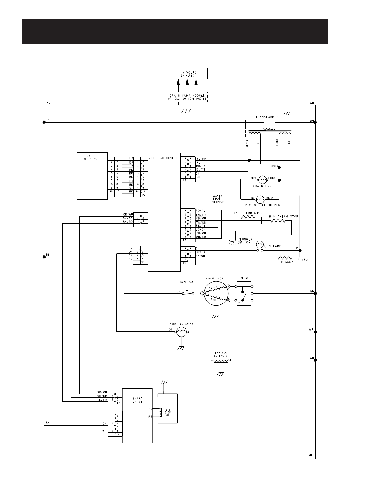
Schematics and Strip Circuits
Refer to the mini-manual attached to the unit.
– 42 –
(Continued next page)
Page 43

Clean Mode Strip Circuit
Bk
Electronic Control
Rd
Water Recirculation Pump
Rd/BkBu
Timing
Time = 20 Min
Wh
Transformer
Flush Mode Strip Circuit
Transformer
Bk
Wh
Bk
Bk
BK
Rd
Vi
Rd
Electronic Smart Valve
Electronic
Control
GY
Electronic Smart Valve
Bu
Bu/Yl
Hot Gas Solenoid
Overload
Water Valve
Water Recirculation Pump
Water Valve
Compressor
Reserve Drain Pump
Relay
Rd/Bk
Rd/Bk
Wh
Wh
Timing
Fill Reservoir
or
Wh
Time = 2 Min
Time = 1 Min
Time = 30 Sec
Fill Reservoir
Volume to Matching
Wh
Thickness Setting
Ice Making Mode Strip Circuit
Transformer
Bk
Wh
Harvest Mode Strip Circuit
Transformer
Bk
Wh
Rd
Bk
Bk
Electronic
Control
Rd
Bk
Bu/Yl
Vi
Rd
Electronic Smart Valve
Electronic
Control
GY
Reserve Drain Pump
Overload
Water Valve
Bu
Water Recirculation Pump
Or
Hot Gas Solinoid
Compressor
Condenser Fan
Relay
Rd/Bk
Wh
Wh
Wh
Timing
Time = 30 Sec
Fill Reservoir
Volume to Matching
Thickness Setting
Rd/Bk
Wh
Rd
– 43 –
Overload
Compressor
Wh
Relay
Page 44

Warranty
What Is Covered:
From the Date of the Original Purchase
Limited One-Year Warranty:
For one year from date of original purchase, we will provide, free of charge, parts and service labor in
your home to repair or replace any part of the icemaker that fails because of a manufacturing defect.
Limited Five-Year Warranty:
For fi ve years from date of original purchase, we will provide, free of charge, parts and service labor in
your home to repair or replace any part of the sealed icemaking system (the compressor, condenser,
evaporator and all connecting tubing) that fails because of a manufacturing defect.
This warranty is extended to the original purchaser and any succeeding owner for products purchased
for ordinary home use in the 48 mainland states, Hawaii, Washington, D.C. or Canada. If the product is
located in an area where service by a GE Authorized Servicer is not available, you may be responsible for
a trip charge or you may be required to bring the product to an Authorized GE Service location for service.
In Alaska the warranty is the same except that it is LIMITED because you must pay to ship the product to
the service shop or for the service technician’s travel costs to your home.
icemaker
icemaker.
– 44 –
 Loading...