

Page 1

Installation
Instructions
31-30246
10-08 JR
Built-In Dishwashers
*Custom front panel models include a kit that
contains a template, hardware and panel
installation instructions. Refer to the kit
instructions when installing the custom panel.
Page 2

Safety Information
2
CONTENTS
Installation Preparation
Parts Supplied......................................................................................3
Materials You Will Need ..................................................................3
Tools You Will Need ..........................................................................3
Advance Planning..............................................................................4
Prepare Dishwasher Enclosure....................................................4
Prepare Drain Plumbing..................................................................5
Prepare Electrical Wiring................................................................6
Prepare Hot Water Line ..................................................................7
Installation Instructions
Step 1, Locate Installation Items ................................................7
Step 2, Install Trim Pieces ..............................................................7
Step 3, Check Door Balance..........................................................8
Step 4, Remove Wood Base, Install Leveling Legs ............8
Step 5, Remove ToeKick..................................................................8
Step 6, Remove ToeKick Brace ....................................................8
Step 7, Install Power Cord..............................................................9
Step 8, Install 90° Elbow..................................................................9
Step 9, Position Water Line and Housing Wiring................9
Step 10, Install Drain Hose to Dishwasher Drain Port......9
Step 11, Insert Drain Hose Through Cabinet......................10
Step 12, Slide Dishwasher
Three-Fourths of the Way Into Cabinet................................10
Step 13, Slide Dishwasher Into Final Position ............10, 11
Step 14, Level Dishwasher ..........................................................11
Step 15, Secure Dishwasher
to Countertop or Cabinet ............................................................12
Step 16, Connect Water Supply ..............................................12
Step 17, Connect Drain Line ......................................................13
Step 18, Connect Power Supply ..............................................14
Step 19, Pretest Checklist ............................................................14
Step 20, Dishwasher Wet Test ..................................................15
Step 21, Set Water Hardness ....................................................15
Step 22, Install Sound Upgrade Kit if Equipped ................15
Step 23, Install ToeKick ..............................................Back Cover
Step 24, Literature........................................................Back Cover
BEFORE YOU BEGIN
Read these instructions completely and carefully.
•
IMPORTANT— Save these instructions for
local inspector’s use. Observe all governing codes and
ordinances.
• Note to Installer — Be sure to leave these
instructions with the Consumer.
• Note to Consumer — Keep these instructions
with your Owner’s Manual for future reference.
• Skill Level — Installation of this dishwasher requires
basic mechanical and electrical skills. Proper
installation is the responsibility of the installer.
Product failure due to improper installation is not
covered under the GE Appliance Warranty.
• Completion Time — 1 to 3 Hours.
New installations require more time than replacement
installations.
•
IMPORTANT— The dishwasher MUST
be installed to allow for future removal from
the enclosure if service is required.
• If you received a damaged dishwasher, you should
immediately contact your dealer or builder.
READ CAREFULLY.
KEEP THESE INSTRUCTIONS.
FOR YOUR SAFETY
Read and observe all CAUTION and WARNINGS shown
throughout these instructions.
While performing installations described in this booklet,
gloves, safety glasses or goggles should be worn.
For Monogram local service in your area, 1.800.444.1845.
For Monogram parts and accessories, call 1.800.626.2002.
For Monogram parts and accessories in Canada,
call 1.800.561.3344.
Page 3
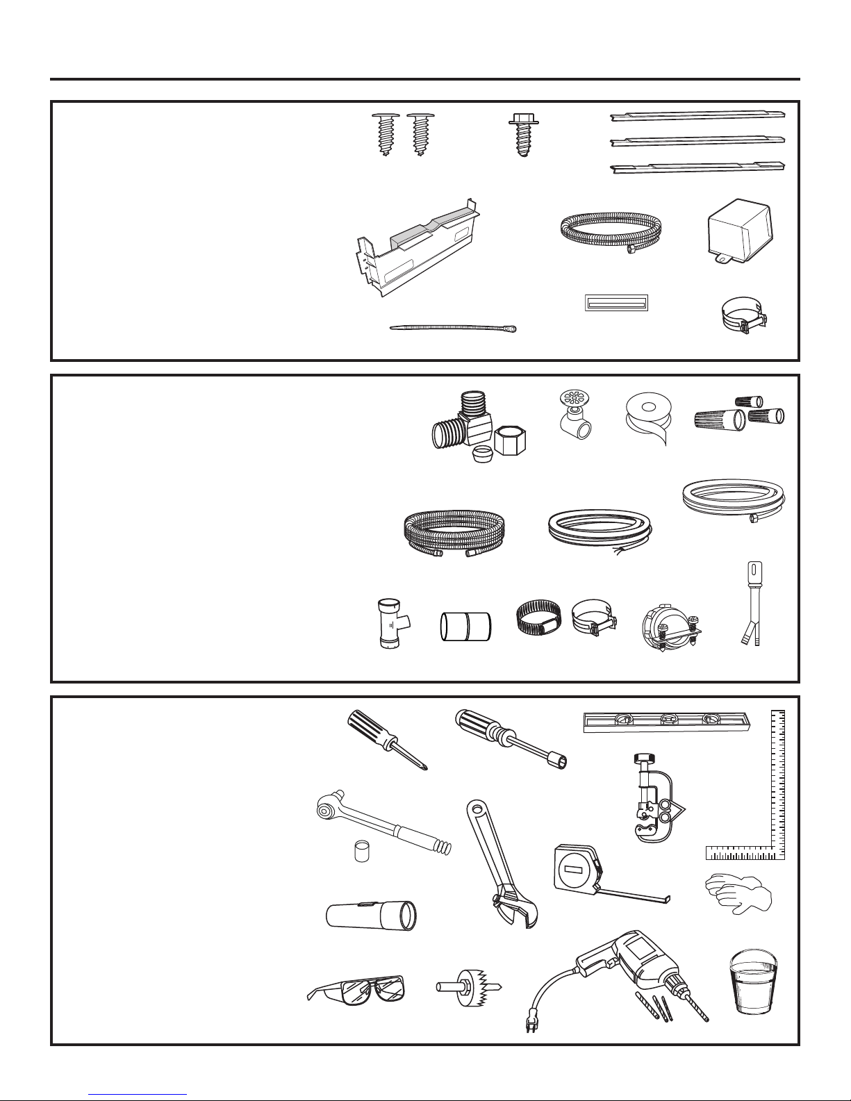
TOOLS YOU WILL NEED:
• Phillips-head screwdriver
• 5/16" and 1/4" nutdriver
• 6" Adjustable wrench
• Level
• Carpenter's square
• Measuring tape
• Safety glasses
• Flashlight
• Bucket to catch water when flushing the line
• 15/16" socket (optional for skid removal)
• Gloves
For New Installations Only:
• Tubing cutter
• Drill and appropriate bits
• Hole saw set
MATERIALS YOU WILL NEED:
• Ferrule, compression nut and 90° Elbow (3/8" NPT
external thread on one end, opposite end sized to fit
water supply)
• Thread seal tape
• UL-Listed wire nuts (3)
Materials For New Installations Only:
• Air gap for drain hose, if required
• Waste tee for house plumbing, if applicable
• Electrical cable or power cord, if applicable
• Screw-type hose clamps
• Strain relief for electrical connection
• Hand shut-off valve
• Water line 3/8" min. copper
• Coupler for extending drain line, if applicable
• GPF10L 10' drain hose, if needed
PARTS SUPPLIED:
• Two #8-18 x 5/8" Phillips special-head
screws, to secure dishwasher to underside
of countertop or sides of cabinets.
• Junction box cover and #10-1/2" hex
head screw
• Side and top trim
• Sound upgrade kit (some models)
• Drain hose (78"), drain hose hanger
and hose clamp
• Literature, Product Samples
and/or coupons
• Hard water test strip
(Models with Bulk Dispenser)
Installation Preparation
3
Wire Nuts (3)
Hot Water Line
Screw-Type
Hose Clamps
Coupler
Hand
Shut-Off
Valve
#8 Phillips Special-Head
Screws 5/8" Long
Hole Saw Set
Measuring Tape
Tubing Cutter
Drill and Bits
Phillips-Head
Screwdriver
15/16" Socket
1/4" and 5/16"
Nutdriver
Safety Glasses
6" Adjustable
Wrench
Bucket
Flashlight
Gloves
Carpenter's
Square
Level
Thread
Seal Tape
GPF10L
10' Drain Hose
Air Gap
Strain Relief
Drain Hose (78")
Hose Clamp
90° Elbow, Ferrule and
Compression Nut
Electrical Cable
(or Power Cord, if applicable)
Waste Tee
Trim Pieces
#10 Hex Head
J-Box Screw
1/2" Long
Drain Hose Hanger
Hard Water Test Strip
(Models with Bulk Dispenser)
Sound Upgrade
Kit (Some Models)
Side Trim
Top Trim
Side Trim
Junction Box Cover
Page 4

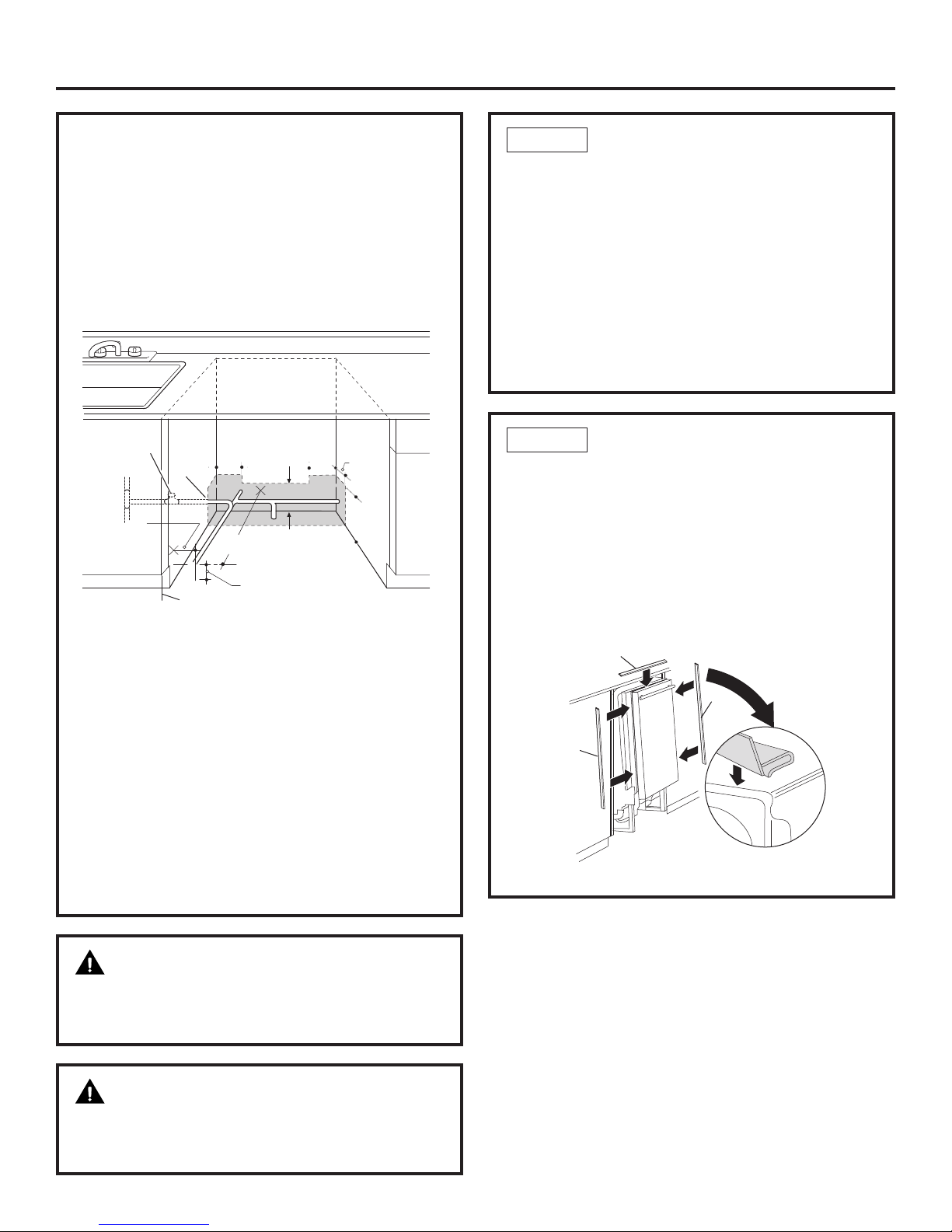
PREPARE DISHWASHER ENCLOSURE
*Dishwasher models ZBD6900PII and ZBD8900PII require a 3/4" thick
custom panel and will be 24-3/4" deep.
• The rough cabinet opening must be at least 24"
deep, 24" wide and approximately 34-1/2" high
from floor to underside of the countertop.
• The back wall should be free of pipes or wires.
• Adjacent cabinets should be square and plumb
to ensure a good fit (Figure A).
• For a corner installation, allow 2" minimum
clearance between the dishwasher and the
adjacent wall.
• Plumbing and electrical service must enter
the shaded area.
• The dishwasher must be installed so that the drain
hose is no more than 10 feet in length for proper
drainage.
• Provide at least 28-3/8" in front of the dishwasher to
allow the dishwasher door to open fully (Figure B).
• Make sure the floor is level inside the opening and
even with the finished floor of the kitchen. This will
facilitate removal of the dishwasher at a later date
for service, if needed.
WARNING
To reduce the risk of electric shock, fire,
or injury to persons, the installer must
ensure that the dishwasher is completely
enclosed at the time of installation.
Special consideration for a dishwasher
installed on a elevated platform
The elevated platform must be flat
and level.
• The dishwasher must be installed no
more than 10 feet from a sink for proper
drainage.
• The dishwasher must be fully enclosed
on the top, sides and back.
• The dishwasher must not support any
part of the enclosure.
Installation Preparation
CLEARANCES: In a corner
installation, provide at least
2" clearance between the
dishwasher and the adjacent
cabinet, wall or other
appliance.
Provide at least 28-3/8" of
clearance in front of the
dishwasher (Figure B).
4
ADVANCE PLANNING
• These dishwashers are designed for versatility,
adaptable to virtually any installation.
• All models have a full-length door without
the traditional access panel.
• These dishwashers may be installed beneath
countertops of stone or other materials that will
not accept screws. No trim kit required.
Figure A
Figure B
Floor MUST
be Even with
Room Floor
34-1/2" ± 1/4"
Underside of
Countertop
to Floor
This Wall Area
must be Free of
Pipes or wires
Cabinets
Square
and
Plumb
24"Min.
24"
24"
34"
Adjustable
to 35"
24"Min.
Countertop
Dishwasher
5" 5"
4"
4"
6"
2" Minimum
28-3/8"Min.
Page 5
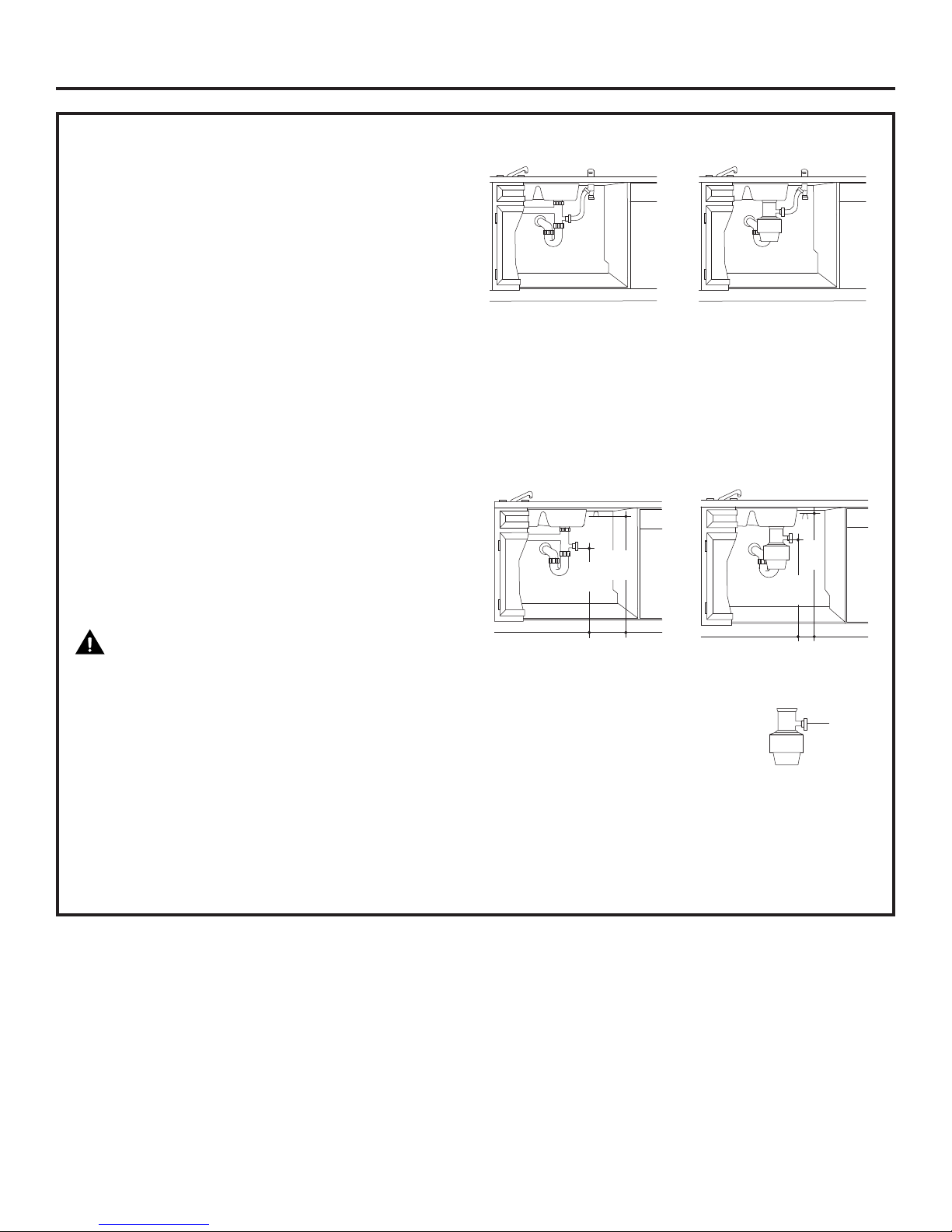
PREPARE DRAIN PLUMBING
Drain Requirements
• Drain hose must not exceed 10 feet in length.
• A high drain loop or air gap is required. See below.
Drain Method
The type of drain installation depends on the
following:
• Do local codes or ordinances require an air gap?
• Is waste tee less than 18" above the floor?
If the answer to either question is yes, an air gap
must be used. Refer to Method 1 (Figure C) in the
adjacent illustrations.
If both answers are no, either an air gap or high drain
loop may be used. Refer to Method 1 (Figure C) or
Method 2 (Figure D) in the adjacent illustrations.
NOTE: Drain hose elevation must not exceed 48".
Special consideration for a dishwasher installed
on a elevated platform
lf the dishwasher is installed on an elevated platform,
a high drain loop of at least 32" above the platform
must be provided in addition to the air gap or drain
loop requirement determined above. This is
necessary for proper drain performance.
CAUTION:An air gap MUST BE USED if
the drain hose is connected to waste tee or disposer
lower than 18" above the floor level. Failure to provide
the proper drain connection height with an air gap or
32" minimum high drain loop will result in improper
draining of the dishwasher, which may cause
damage.
Cabinet Preparation for drain line
Drill a 1-1/2" dia. hole in the cabinet wall within the
shaded areas shown in Figure A for the drain hose.
Make sure there are no sharp edges. The drain hose
will be passed through this hole and connected to
the drain in a later step.
Method 1—Air Gap with Waste Tee or Disposer
Method 2—“High Drain Loop” with Waste Tee or
Disposer
Use the drain hose hanger included in the installation
kit to attach the drain hose to the underside of the
countertop. Attachment will be made in a later step.
Install waste tee or disposer and the air gap according
to the manufacturer’s instructions.
Figure C
Figure D
IMPORTANT— When
connecting drain line to disposer,
check to be sure that drain plug has
been removed. DISHWASHER WILL
NOT DRAIN IF PLUG IS LEFT IN PLACE.
5
Installation Preparation
Disposer Installation
Waste Tee Installation
Disposer Installation
Waste Tee Installation
18"
Min.
18"
Min.
Remove
Hopper
Plug
32"
Min.
32"
Min.
Page 6

6
Installation Preparation
PREPARE ELECTRICAL WIRING
WARNING
FOR PERSONAL SAFETY: Remove house fuse
or open circuit breaker before beginning
installation. Do not use an extension cord
or adapter plug with this appliance.
Electrical Requirements
• This appliance must be supplied with 120V, 60 Hz. and
connected to an individual properly grounded branch
circuit, protected by a 15- or 20-ampere circuit breaker
or time-delay fuse.
• Wiring must be 2-wire with ground and rated for
75°C (176°F).
• If the electrical supply does not meet the above
requirements, call a licensed electrician before
proceeding.
Grounding Instructions—Permanent Connection
This appliance must be connected to a grounded metal,
permanent wiring system, or an equipment-grounding
conductor must be run with the circuit conductors and be
connected to the equipment-grounding terminal or lead on
the appliance.
Grounding Instructions—Power Cord Models
This appliance must be grounded. In the event of a
malfunction or breakdown, grounding will reduce the risk
of electric shock by providing a path of least resistance for
electric current. This appliance is equipped with a cord
having an equipment-grounding conductor and a
grounding plug. The plug must be plugged into an
appropriate outlet that is installed and grounded in
accordance with all local codes and ordinances.
WARNING
The improper connection of the equipmentgrounding conductor can result in a risk
of electric shock. Check with a qualified
electrician or service representative if you
are in doubt that the appliance is properly
grounded.
For models equipped with power cord: Do not modify the
plug provided with the appliance; if it will not fit the outlet,
have a proper outlet installed by a qualified technician.
Cabinet Preparation and Wire Routing
• The wiring may enter the opening from either
side, rear or the floor within the shaded area
dimensioned in Figure A and illustrated above.
• Cut a 1-1/2" max. dia. hole to admit the electrical
cable. Cable direct connections may pass through
the same hole as the drain hose and hot water line,
if convenient. If cabinet wall is metal, the hole edge
must be covered with a bushing.
• NOTE: Power cords with plug must pass through
a separate hole.
Electrical Connection to Dishwasher
Electrical connection is on the right front of dishwasher.
• For cable direct connections the cable must be routed
as shown in Figure E. Cable must extend a minimum
of 24" from the rear wall.
• For power cord connections, install a 3-prong
grounding-type receptacle in the sink cabinet
rear wall, 6" min. or 18" max. from the opening,
6" to 18" above the floor. The receptacle must be
accessible and therefore cannot be installed in
the back wall of the dishwasher enclosure.
Figure E
Alternate
Receptacle
Location
1-1/2" Dia.
Hole (Max.)
Receptacle
Location Area
3" from
Cabinet
24" from
Wall
Ground
Black
White
18"
18"
6"
6"
Page 7
PREPARE HOT WATER SUPPLY
Hot Water Line
• The line may enter from either side, rear or floor within
the shaded area shown in Figure F.
• The line may pass through the same hole as the
electrical cable and drain hose, or an additional
1-1/2" diameter hole may be cut to accommodate
the water line. If a power cord with plug is used, the
water line must not pass through the power cord hole.
Water Line Connection
• Turn off the water supply.
• Install a hand shut-off valve in an accessible location,
such as under the sink. (Optional, but strongly
recommended and may be required by local codes.)
• The water connection is on the bottom left side
of the dishwasher. Install the hot water inlet line, using
3/8" or larger copper tubing. Route the line as shown in
Figure F and extend forward at least 19" from rear wall.
• Adjust the water heater to deliver water between 120°F
and 150°F.
• Flush water line to clean out debris. Use a bucket to
catch water and debris.
• The hot water supply line pressure must be between
20 and 120 PSI.
Installation Instructions
7
CAUTION
The hot water supply line pressure must be at least
20 PSI. Lower pressures could cause the water valve
to leak and cause water damage.
CAUTION
Do not remove wood base until you are ready to install
the dishwasher. The dishwasher will tip over when the
door is opened if the wood base is removed.
Figure F
INSTALL TRIM PIECES
In this step, you will need the trim pieces set aside
in Step 1.
• Press top trim piece onto top of tub flange. Start with
the right edge and work your way to the left.
• Repeat process with the left and right trim pieces
working from the top down.
• Open and close the door to check that trim does not
bind and does not interfere with door latch or door
hinges.
STEP 2
LOCATE INSTALLATION ITEMS
• Locate the items in the installation package and set
aside for use in the listed steps.
• Trim pieces – Step 2
• Junction box cover – Step 7 or Step 18
• Drain hose and clamp – Step 10
• Screw kit – Step 15
• Drain hose hanger – Step 17
• Owner’s Manual – Step 19 and Step 24
• Hard water test strip – Step 21
• Sound upgrade kit (selected models) – Step 22
• Product samples and/or coupons – Step 24
STEP 1
Figure G
2" From Floor
Shut-off
Valv e
Hot
5"
5"
4"
4"
6"
19" From Wall
2"
From
Cabinet
1-1/2"
Dia.
Hole
Cabinet Face
Trim
Strip
Trim
Strip
Trim
Strip
Page 8
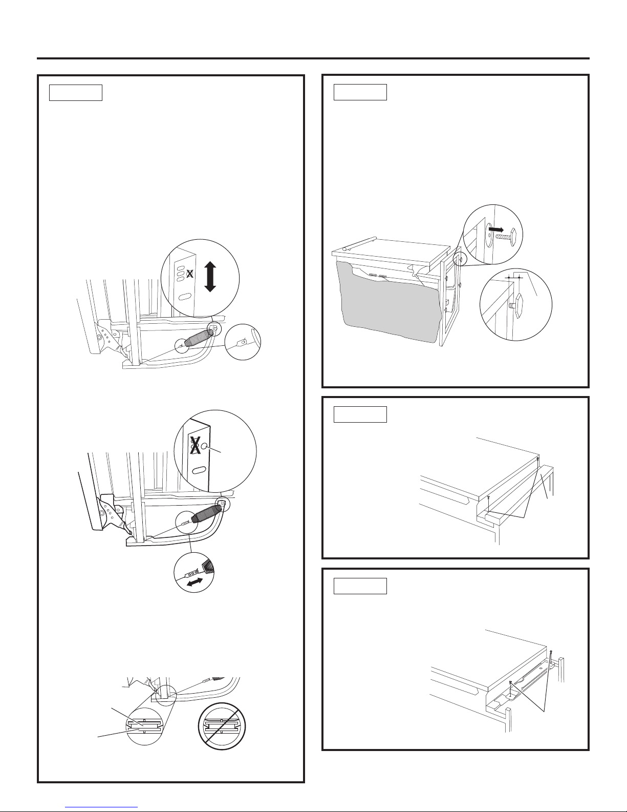
REMOVE WOOD BASE, INSTALL
LEVELING LEGS
IMPORTANT — Do not kick off wood base!
Damage will occur.
• Move the dishwasher close to the installation location and lay
it on its back.
• Remove the four leveling legs on the underside of the wood base
with an adjustable wrench or 15/16" socket.
• Discard base.
• Screw leveling legs back into the dishwasher frame approximately
1/8" from frame as shown.
STEP 4
REMOVE TOEKICK
• Remove the 2 toekick
screws and toekick.
Set aside for use
in Step 23.
STEP 5
Installation Instructions
Figure K
Figure L
CHECK DOOR BALANCE
• With dishwasher on the wood skid, check the door
balance by opening and closing the door.
• If the door drops when released, increase the spring tension.
If the door rises when released, decrease the tension.
• There are two types of counter balance and therefore two
methods of adjustment. Identify which counter balance is
present and adjust tension accordingly. Please note: if
there are 3 holes on the cable, use the cable to adjust;
if there is one hole on cable use the tub leg to adjust.
Type 1 – One-hole cable
Adjust tension by moving spring hook to one of the three
holes on the tub leg.
Type 2 – Three-hole cable
Adjust tension by moving spring hook to one of the three
holes on the pulley cable.
After adjusting spring tension, open and close the door to
make sure the door operates smoothly. If the door is hard
to move or if the spring cable binds, check the routing of
the spring cable. The cable should be routed between the
shoulders of the pulley cable roller. If the cable is off the
roller: latch door, remove spring tension and route the
cable between the shoulders of the roller. See Figure J.
STEP 3
Figure H
Figure I
Figure J
Correct Spring
Cable Routing
Pulley
Shoulder
Incorrect Spring
Cable Routing
REMOVE TOEKICK BRACE
Skip this step if your model does not have a sound upgrade kit.
If your model does have a sound upgrade kit, this brace must
be removed.
• Remove the 2 toekick
brace screws and
toekick brace.
Discard brace
and set screws
aside for use in
Step 22.
STEP 6
Figure M
INCREASE
DECREASE
One Hole
Approx.
1/8"
Remove 2
Toekick Screws
Toekick
Use This
Mounting
Hole
Decrease
Tension
Increase
Tension
8
Remove 2
Toekick Screws
Page 9

INSTALL DRAIN HOSE TO
DISHWASHER DRAIN PORT
In this step you will need the drain hose and clamp set
aside in Step 1.
• Stand the dishwasher upright.
• Place drain hose clamp over 1-3/16" inside diameter
end of drain hose with the clamp screw positioned
on the bottom of the hose.
IMPORTANT — Prevent drain hose damage and
possible leaks. Be careful not to nick or cut the drain hose.
• Push the end of the drain hose over the drain pump
outlet being careful not to disturb the check valve.
Refer to Figure Q.
• Seat the drain hose end against the hose stops on
the pump outlet.
• Position hose clamp against the front lip of the drain
hose and tighten clamp.
NOTE: Drain hose
supplied with
dishwasher is
approximately 78"
long. If a longer hose
is needed, a 120"
long hose (10 feet)
may be purchased
from an authorized
GE appliance dealer.
The 10' long hose is
part number GPF10L.
Tip for leak-free
connections:
• Insert hose against stop on pump.
• Position clamp against front lip of drain hose.
• Tighten clamp to at least 15 inch-pounds of torque.
Tip for quiet drain pump operation:
Position hose clamp with clamp screw on the bottom side
of the hose. This will prevent the clamp from coming in
contact with the rear brace. Clamp contact with the rear
brace could create noise when the drain pump is running.
STEP 10
POSITION WATER LINE AND
HOUSING WIRING
• Position water supply line and house wiring on the floor
of the enclosure to avoid interference with base of
dishwasher and components under dishwasher.
STEP 9
9
Installation Instructions
Figure P
INSTALL POWER CORD
Skip this step if dishwasher will be permanently connected to
the house electrical system.
In this step you will need the junction box cover and the #10 x 1/2"
hex head screw from the screw kit set aside in Step 1.
The power cord and connections must comply with the National
Electrical Code, Section 422 and/or local codes and ordinances.
Maximum power cord length is 6 feet. Power Cord Kit WX09X70910,
available for purchase from an authorized GE Appliance Dealer,
meets these requirements.
• Install strain relief in junction box bracket.
• Insert power cord through strain relief and tighten.
• Make sure black, white and green dishwasher wires are threaded
through small hole in junction box bracket.
• Connect like-colored dishwasher and power cord wires. If power
cord wires are not color coded, connect the ribbed power cord
wire to the white dishwasher wire, the smooth power cord wire
to the black dishwasher wire and the ground to the green
dishwasher wire. Use UL-listed wire nuts of appropriate size.
• Install junction box cover set aside in Step 1, using #10 hex head
screw. Be sure wires are not pinched under the cover.
STEP 7
Figure N
INSTALL 90° ELBOW
• Wrap 90° elbow with thread seal tape.
• Install a 90° elbow onto the water valve.
• Do not overtighten 90° elbow, water valve bracket could bend
or water valve fitting could break.
• Position the end of the elbow to face the rear of the dishwasher
.
STEP 8
Figure O
Figure Q
Pump
Outlet
Hose Clamp
Hose Stops
Hose Clamp
Check Valve
Do Not Remove
Front of Dishwasher
Water Valve
Bracket
Water
Line
House
Wiring
5"
5"
4"
4"
6"
Fill Hose
Thread Seal Tape
90˚ Elbow
Ground
Black
White
Page 10

SLIDE DISHWASHER INTO
FINAL POSITION
STEP 13
10
• Push the dishwasher the rest of the way into
the cabinet.
• Push the sides with your hands. Do not push the
dishwasher with your knee, as this will damage
the door.
• Check that the tub insulation blanket does not get
“bunched-up” or interfere with the springs as you
slide it into the cabinet.
• Center the dishwasher in the opening.
• Front of door panel should be flush with face of
cabinet.
• Carefully open and close the door to ensure that
the door panel does not catch or rub on the cabinet
frame. Refer to Figure T below.
• If the door catches or rubs on the frame, reposition
and/or level the unit (see Step 14) until the door moves
freely and does not contact the cabinet frame.
Installation Instructions
Figure T
INSERT DRAIN HOSE
THROUGH CABINET
• Position dishwasher in front of cabinet opening. Insert
drain hose into the hole in cabinet side. If a power cord is
used, guide the end through a separate hole.
TIP: Position water line and house wiring on the floor
to avoid interference with base of dishwasher.
STEP 11
SLIDE DISHWASHER THREEFOURTHS OF THE
WAY INTO CABINET
IMPORTANT — DO NOT PUSH AGAINST
FRONT PANEL WITH KNEES. DAMAGE WILL OCCUR.
• Grasp the dishwasher by its sides and slide it into
the opening a few inches at a time.
• As you proceed, pull the drain hose through the opening
under the sink. Stop pushing when the front of the
dishwasher is a few inches forward of adjacent cabinets.
• Make sure drain hose is not kinked under the
dishwasher and there is no interference with
the water line, wiring or any other component.
TIP: Make sure the dishwasher will fit in the cabinet.
Check to be sure the power cable, drain hose, and hot
water line are not trapped behind the dishwasher. Utility
lines trapped behind the dishwasher prevent the
dishwasher from being pushed fully into the enclosure.
STEP 12
Figure S
Do not push against front door
panel with knee. Damage to
the door panel will occur.
Figure R
Power Cord
(If Used)
Drain
Hose
Water
Line
Insulation
Blanket
House Wiring
(If Power Cord
is NOT Used)
Door Fits and
Swings Back
Behind Cabinet
Frame
Door Catches on
Cabinet Frame
Incorrect
Alignment
Correct
Alignment
Maximum
Drain Hose
Length 10'
Page 11

LEVEL DISHWASHER
IMPORTANT — Dishwasher must be level for
proper dish rack operation and wash performance.
• Make sure 1/2" minimum gap is maintained.
• Place level on door
to check that the
dishwasher is level
side to side.
Remove lower
rack, place
level on lower
rack track inside
tub to check that
the dishwasher is
level front to back.
• If the dishwasher is not level, adjust the four leveling
legs as illustrated in Figure X.
• If adjustment to the right rear leveling leg is required,
access it by loosening the junction box bracket screw
(through the access hole) and rotate bracket clockwise.
• The dishwasher is properly leveled when the level
indicator is centered left to right and front to back.
The dishwasher door should close without hitting
the sides of the tub.
• Replace the lower rack when leveling is complete.
TIP: Avoid unnecessary service charges for poor wash
performance and rack operation.
Pull the dish racks halfway out. They should remain
stationary. Open and close the door. The door should fit
in the tub opening without hitting the side of the tub. If
the racks roll on their own, or the door hits the side of
the tub, relevel the dishwasher.
IMPORTANT — After leveling, verify that
the dishwasher is centered in the enclosure and the
door does not hit adjacent cabinets.
STEP 14
11
Installation Instructions
Figure W
Figure X
SLIDE DISHWASHER INTO
FINAL POSITION (cont.)
STEP 13
Special Considerations for Positioning
The controls on these models are designed to be hidden
by your countertop. Align the dishwasher as shown in
Figure U. Leave a 1/2" minimum gap between the
underside of the countertop and the top of the
dishwasher door as shown in Figure V.
Use the leveling legs to increase or decrease the amount
of gap between the controls and the countertop.
IMPORTANT — Leave a 1/2" minimum
gap between the controls and the underside of the
countertop to prevent condensation and damage
to the control panel from screw heads.
Figure V
Figure U
Controls Hidden by
Countertop
Countertop
Countertop
Junction Box
Access Hole
Turn legs
to adjust
Dishwasher Door
1/2"
Min.
Use Level
to Check
Front to
Back
Use Level
to Check
Side to Side
Page 12

CONNECT WATER SUPPLY
Connect water supply line to 90° elbow.
• Slide compression nut, then ferrule over end of
water line.
• Insert water line into 90° elbow.
• Slide ferrule against elbow and secure with
compression nut.
IMPORTANT — Check to be sure that
door spring does not rub or contact the fill hose
or water supply line. Test by opening and closing
the door. Reroute the lines if a rubbing noise or
interference occurs.
STEP 16
12
Installation Instructions
Figure CC
SECURE DISHWASHER TO
COUNTERTOP OR CABINET
STEP 15
In this step you will need
the 2 Phillips specialhead screws set aside
in Step 1.
The dishwasher must be
secured to the
countertop or the
cabinet sides. When
countertops are made of
wood, use Method 1. When countertops are granite
or other materials that will not accept screws, use
Method 2 to secure dishwasher at the sides.
IMPORTANT — Avoid unnecessary service
charges. Drive screws straight and flush.
Protruding
screw heads
will scratch the
top or sides of
the control
panel and can
interfere with
door closing.
Method 1—Secure dishwasher to wood
countertop
• Fasten the dishwasher to the underside of the
countertop with 2 Phillips special-head screws
provided.
Method 2—Secure dishwasher with side-mounting
brackets
• Remove plug buttons (one on each side).
• Install screws through the dishwasher side mount
bracket and
into the
adjacent
cabinet on
each side.
Reinstall plug
buttons.
Either Method—Make certain 1/2" gap minimum
is maintained.
• When step is complete, close dishwasher door
and verify that gap between countertop and top
of dishwasher door is at least 1/2".
Figure Y
Figure Z
Figure BB
Figure AA
Screws
Side Mounting
Brackets
Tub
Frame
Countertop
Mounting
Brackets
Compression Nut
Ferrule
90˚ Elbow
90˚ Elbow
Hot Water
Supply Line
Door Spring
Brackets
Wood Countertop
Stone Countertop
Side Mounting Brackets
Plug Buttons
Screws
Countertop
Dishwasher Door
1/2"
Min.
Page 13

13
Installation Instructions
CONNECT DRAIN LINE
The molded end of the drain hose will fit 5/8" through
1" diameter inlet ports on the air gap, waste tee or
disposer.
• Determine size of inlet port.
• Cut drain hose connector on the marked line,
if required, to fit the inlet port.
• If a longer drain hose is required, and you did not
purchase 10' long GPF10L drain hose, add up to
3-1/2' of length for a total of 10' to the factory
installed hose. Use 5/8" or 7/8" inside diameter
hose and a coupler to connect the two hose ends.
Secure the connection with hose clamps.
NOTE: TOTAL DRAIN HOSE LENGTH MUST NOT EXCEED
10' FOR PROPER DRAIN OPERATION.
DRAIN LINE INSTALLATION
• Connect drain line to air gap, waste tee or disposer
using the previously determined method.
• Secure the drain hose to the air gap, waste tee or
disposer with clamps.
Method 1—Air gap with waste tee or disposer
Insert the drain hose into the air gap as shown.
Method 2—High Drain Loop with the Waste Tee
or Disposer
Route the drain hose of the dishwasher to a
minimum height of 32" from the floor with the
supplied hanger as shown.
IMPORTANT — One of the above methods
must be used or dishwasher will not operate
properly.
IMPORTANT — When
connecting drain line to disposer,
check to be sure that drain plug
has been removed. DISHWASHER
WILL NOT DRAIN IF PLUG IS LEFT IN PLACE.
TIP: Avoid unnecessary service call charges. Always
be sure disposer drain plug has been removed before
attaching dishwasher drain hose to the disposer.
STEP 17
Figure DD
Figure EE
Figure FF
Waste Tee Installation Disposer Installation
Figure GG
Disposer InstallationWaste Tee Installation
Cutting Line
Hose Clamp
Hose Clamp
Fasten to underside
of countertop
18"
Min.
18"
Min.
32"
Min.
32"
Min.
Fasten to underside
of countertop
Coupler
IMPORTANT: Do not cut corrugated
portion of hose
1"
5/8"
Remove
Hopper
Plug
Page 14

14
Installation Instructions
PRETEST CHECK LIST
Review this list after installing your dishwasher
to avoid charges for a service call that is not
covered by your warranty.
• Check to be sure power is OFF.
• Open door and remove all foam and paper
packaging.
• Locate the Owner’s Manual set aside in Step 1.
• Read the Owner’s Manual for operating instructions.
• Check door opening and closing. If door does not
open and close freely, check for proper routing of
spring cable over pulley. If door drops or closes
when released, adjust spring tension. See Step 3,
Figure J.
• Check to be sure that wiring is secure under the
dishwasher, not pinched or in contact with door
springs or other components. See Step 9.
• Check door alignment with tub. If door hits tub,
level dishwasher. See Step 14.
• Pull lower rack out about halfway. Check to be
sure it does not roll back or forward on the door.
If the rack moves, adjust leveling legs. See Step 14.
• Check door alignment with cabinet. If door hits
cabinet, reposition or relevel dishwasher. See
Steps 13, 14 and 15.
• Check that door spring does not contact water line,
fill hose, wiring or other components. See Step 16.
• Verify water supply and drain lines are not kinked
or in contact with other components. Contact with
motor or dishwasher frame could cause noise.
See Steps 9 and 11.
• Turn on the sink hot water faucet and verify water
temperature. Incoming water temperature must
be between 120°F and 150°F. A minimum of 120°F
temperature is required for best wash performance.
See “Prepare Hot Water Line,” page 7.
• Add 2 quarts of water to the bottom of the
dishwasher to lubricate the pump seal.
• Turn on water supply. Check for leaks. Tighten
connections if needed.
• Remove protective film if present from the control
panel and door.
• Avoid service call charges by ensuring there is
an air gap or drain hose routed through the
required 32" minimum height.
STEP 19
CONNECT POWER SUPPLY
Skip this step if dishwasher is equipped with
power cord.
Verify that power is turned off at the source.
• Locate junction box cover set aside in Step 1.
• Secure house wiring to the back of the junction
box with a strain relief.
• Locate the three dishwasher wires, (white, black
and green) with stripped ends. Insert dishwasher
wires through the small hole in the junction box.
Connect like-colored dishwasher and power cable
wires using UL-listed wire nuts of appropiate size.
• Install the junction box cover. Check to be sure
that wires are not pinched under the cover.
WARNING
If house wiring is not 2-wire with
ground, a ground must be provided
by the installer. When house wiring
is aluminum, be sure to use UL-listed
anti-oxidant compound and
aluminum-to-copper connectors.
STEP 18
Ground
Black
White
Figure HH
Page 15

15
SET WATER HARDNESS
Models with bulk dispenser only. Skip this step if your
dishwasher does not have the bulk dispense feature.
• Locate the hard water test strip set aside in Step 1.
• Remove strip from package.
• Turn on the hot water and hold the strip under the stream,
following the directions on the package.
• Use the value on the test strip to calibrate your dishwasher
for water hardness. Refer to the section titled "Water
Hardness Calibration" in your Owner's Manual for
information on how to calibrate your dishwasher.
STEP 21
Installation Instructions/Custom Panel Dimensions
DISHWASHER WET TEST
• Turn on power supply (or plug power cord into outlet,
if equipped).
• Start the unit to check for leaks.
– Push RINSE ONLY pad.
– Push START/RESET pad one time.
– Close door.
• Check to be sure that water enters the dishwasher. If water
does not enter the dishwasher, check to be sure that water
and power are turned on.
• Check for leaks under the dishwasher. If a leak is found,
turn power supply off, then tighten connections. Restore
power after leak is corrected.
• Check for leaks around the door. A leak around the door
could be caused by door rubbing or hitting against
adjacent cabinetry. Reposition the dishwasher if
necessary. See Step 13, 14 and 15.
• The dishwasher will drain and turn off about 5 minutes after
it was started. Check drain lines. If leaks are found, turn off
power supply and correct plumbing as necessary. Restore
power after corrections are made. See Step 10 and 17.
• Open dishwasher door and make sure most of the water
has drained. If not, check that disposer plug has been
removed and/or air gap is clear. See Step 17. Also check
drain line to be sure it is not kinked.
• Run the dishwasher through another “Rinse Only” cycle.
Check for leaks and correct if required.
STEP 20
INSTALL SOUND UPGRADE KIT
IF EQUIPPED
Skip this step if your model does not have the Sound
Upgrade Kit.
• Locate sound upgrade kit set aside in Step 1 and the two
screws set aside in Step 6.
• Attach the plastic Sound Panel as shown in Figure II
using the two screws. The lower set of mounting holes
should be used.
• Be sure the sound panel is seated in the notches on frame
as shown in Figure II.
STEP 22
Sound panel is located
under door panel.
Plastic Sound
Panel with Foam
Attachment
Screws
Be sure that the sound panel is seated
in the notch in the frame. (Both sides)
Figure II
Page 16

Pub. No. 31-30246
Part No. 206C1559P184
10-08 JR
NOTE: While performing installations described in this book,
safety glasses or goggles should be worn.
For Monogram®local service in your area, call
1.800.444.1845.
NOTE: Product improvement is a continuing endeavor at
General Electric. Therefore, materials, appearance and
specifications are subject to change without notice.
GE Consumer & Industrial
Appliances
General Electric Company
Louisville, KY 40225
ge.com
LITERATURE
• Be sure to leave complete literature package, Installation
Instructions and product samples with the consumer.
STEP 24
INSTALL TOEKICK
• Locate toekick and screws set aside in step 5.
• Replace the toekick and make sure it is against the floor.
• Insert and tighten the 2 toekick attachment screws. The
toekick should stay in contact with the floor to ensure quiet
dishwasher operation.
STEP 23
Figure JJ
Attachment
Screws
Toekick
Page 17

Instructions
d’installation
31-30246
10-08 JR
Lave-vaisselle encastré
*Les modèles avec panneau frontal sur
commande viennent avec une trousse
comprenant un gabarit, la quincaillerie et les
instructions d'installation du panneau. Se
reporter aux instructions de la trousse pour
installer le panneau sur commande.
Page 18

Information de sécurité
2
CONTENU
Préparation pour l’installation
Pièces fournies ....................................................................................3
Matériaux nécessaires ....................................................................3
Outils nécessaires..............................................................................3
Planification préalable ....................................................................4
Préparation de l’enceinte du lave-vaisselle ..........................4
Préparation de la plomberie de vidange................................5
Préparation pour le branchement électrique ......................6
Préparation du tuyau d’eau chaude ........................................7
Instructions d’installation
Étape 1, Repérage des articles à installer..............................7
Étape 2, Installation des pièces de finition ............................7
Étape 3, Vérification de l’équilibre de la porte......................8
Étape 4, Retrait de la base en bois,
installation des pattes de nivellement ....................................8
Étape 5, Retrait de la plinthe ........................................................8
Étape 6, Retrait du renfort de plinthe ......................................8
Étape 7, Installation du cordon
d’alimentation électrique................................................................9
Étape 8, Installation du coude à angle droit ........................9
Étape 9, Mise en place du tuyau
d’eau et des fils de la maison ......................................................9
Étape 10, Raccordement du tuyau
de vidange à l’orifice de vidange du lave-vaisselle ..........9
Étape 11, Insertion du tuyau
de vidange à travers l’armoire..................................................10
Étape 12, Glissement du lave-vaisselle
au 3/4 de la distance dans l’armoire ....................................10
Étape 13, Glissement du lave-vaisselle
à sa position finale..................................................................10, 11
Étape 14, Mise à niveau du lave-vaisselle ..........................11
Étape 15, Fixation du lave-vaisselle
au plan de travail ou à l’armoire..............................................12
Étape 16, Raccordement à l’alimentation d’eau..............12
Étape 17, Raccordement du tuyau de vidange................13
Étape 18, Branchement à l’alimentation électrique ......14
Étape 19, Liste de vérification
avant de faire les essais ..............................................................14
Étape 20, Essai du lave-vaisselle avec de l’eau................15
Étape 21, Détermination de la dureté de l’eau ................15
Étape 22, Installation de la trousse d’amélioration
de l’insonorisation (certains modèles)………………………………15
Étape 23, Installation de la plinthe........Couverture arrière
Étape 24, Documentation..........................Couverture arrière
AVANT DE COMMENCER
Il faut lire soigneusement toutes ces instructions.
•
IMPORTANT — Conserver ces instructions afin
que l’inspecteur local s’en serve. Il faut respecter tous
les codes et règlements.
• Remarque pour l’installateur — Ne pas oublier
de remettre ces instructions au consommateur.
• Remarque pour le consommateur — Il faut
garder ces instructions avec le manuel d’utilisation,
pour consultation ultérieure.
• Niveau de compétence — L’installation de ce
lave-vaisselle demande des talents mécaniques et
électriques de base. L’installateur est responsable de
l’installation appropriée. La garantie des appareils
ménagers de GE ne couvre pas les défaillances du
produit causées par une mauvaise installation.
• Durée d’installation — 1 à 3 heures.
Les installations initiales demandent plus de temps que
les installations de remplacement.
•
IMPORTANT — Le lave-vaisselle DOIT être
installé de manière à permettre la dépose ultérieure
de l’enceinte afin de permettre toute intervention.
• Si le lave-vaisselle livré est endommagé, il faut
contacter immédiatement le concessionnaire ou
l’entrepreneur de construction.
LIRE ATTENTIVEMENT.
IL FAUT GARDER CES INSTRUCTIONS.
SÉCURITÉ
Il faut lire et observer tous les avertissements
(PRUDENCE et ATTENTION) montrés dans ces
instructions.
Pendant l’installation décrite dans ce livret, il faut porter
des gants et des lunettes de sécurité.
Pour le service local Monogram dans votre région :
1.800.444.1845.
Pièces et accessoires Monogram, appeler le :
1.800.626.2002.
Pièces et accessoires Monogram au Canada,
appeler le : 1.800.561.3344.
Page 19

OUTILS NÉCESSAIRES :
• Tournevis cruciforme
• Tournevis à douille de 5/16 po et 1/4 po
• Clé à molette de 15 cm (6 po)
• Niveau
• Équerre de menuisier
• Ruban à mesurer
• Lunettes de sécurité
• Lampe de poche
• Seau pour attraper l’eau lors de la purge
du tuyau
• Douille de 15/16 po (optionnelle pour
la dépose de la palette)
• Gants
Pour les installations initiales seulement :
• Coupe-tube
• Perceuse et mèches appropriées
• Scie-cloche
MATÉRIAUX NÉCESSAIRES :
• Bague, écrou de compression et coude à angle droit
(filetage externe de 3/8 po à une extrémité, l’autre
extrémité correspondant à l’alimentation d’eau)
• Ruban d’étanchéité de filetage
• Serre-fils sur la liste UL (3)
Matériaux pour une installation initiale seulement :
• Dispositif anti-siphon pour le tuyau de vidange, si nécessaire
• Raccord en té pour la plomberie d’égout, si nécessaire
• Câble électrique ou cordon d’alimentation, si nécessaire
• Colliers de tuyau à vis
• Dispositif de réduction de tension pour les branchements
électriques
• Robinet de sectionnement
• Tuyau d’eau en cuivre de 3/8 po minimum
• Manchon pour allonger le tuyau de vidange, si nécessaire
• Tuyau de vidange GPF10L de 10 pi, si nécessaire
PIÈCES FOURNIES :
• Deux vis cruciformes spéciales #8-18 x 5/8 po
pour fixer le lave-vaisselle au dessous du plan
de travail ou aux côtés des armoires.
• Couvercle de boîte de jonction et vis
hexagonale #10-1/2 po
• Pièces de finition latérales et supérieure
• Trousse d’amélioration de l’insonorisation
(certains modèles)
• Tuyau de vidange (78 po) avec support
et collier
• Documentation, échantillons de produit
et/ou coupons
• Bande d’analyse de la dureté de l’eau (Modèles
équipés d’un distributeur en vrac)
Préparation pour l’installation
3
Serre-fils (3)
Tuyau d’eau chaude
Colliers de
tuyau à vis
Manchon
Robinet de
sectionnem
ent
Vis cruciformes spéciales
#8, longueur de 5/8 po
Scie-cloche
Ruban à mesurer
Coupe-tube
Perceuse et
mèches
Tournevis
cruciforme
Douille de 15/16
Tournevis à douille
de 5/16 po et 1/4 po
Lunettes de sécurité
Clé à molette
de 15 cm (6 po)
Seau
Lampe de poche
Gants
Équerre de
menuisier
Niveau
Ruban
d’étanchéité
de filetage
Tuyau de vidange
GPF10L de 10 pi
Dispositif de
réduction de tension
Tuyau de vidange (78 po)
Collier de tuyau de vidange
Coude à angle droit, bague
et écrou de compression
Câble électrique (ou cordon
d’alimentation, si nécessaire)
Raccord en té, égout
Pièces des finition
Vis hexagonale #10
pour boîte de jonction,
longueur de 1/2 po
Support de tuyau de vidange
Bande d’analyse de la dureté
de l’eau (Modèles équipés
d’un distributeur en vrac)
Trousse d’amélioration
de l’insonorisation
(certains modèles)
Pièce de finition latérale
Pièce de finition supérieure
Pièce de finition latérale
Couvercle de boîte
de jonction
Dispositif anti-
siphon
Page 20

*Les lave-vaisselle modèles ZBD6900PII et ZBD8900PII nécessitent
un panneau sur commande de 1,9 cm (3/4 po) d’épaisseur et aura
62,9 cm (24-3/4 po) de profondeur.
• L’ouverture de l’armoire doit avoir une profondeur d’au
moins 61 cm (24 po), une largeur d’au moins 61 cm
(24 po) et une hauteur d’environ 88 cm (34-1/2 po),
du sol au dessous du plan de travail.
• Le mur arrière doit être exempt de tuyaux et de fils.
• Les armoires adjacentes doivent être à l’équerre et
d’aplomb pour un ajustement adéquat (Figure A).
• Dans une installation de coin, laissez un dégagement
minimal de 5,1 cm (2 po) entre le lave-vaisselle et
le mur adjacent.
• La plomberie et l’électricité doivent entrer dans la zone
ombrée.
• Le lave-vaisselle doit être installé de manière que le
tuyau de vidange n’ait pas une longueur supérieure
à 3 m (10 pi) afin d’obtenir un bon écoulement.
• Laissez au moins 72 cm (28-3/8 po) à l’avant du lave-
vaisselle pour permettre l’ouverture complète de sa
porte (Figure B).
• Veillez à ce que le plancher soit de niveau à l’intérieur
de l’ouverture et au même niveau que le plancher fini
de la cuisine. Cela facilitera le retrait du lave-vaisselle
dans l’éventualité d’une réparation dans le futur.
AVERTISSEMENT
Pour réduire le risque de choc électrique,
d’incendie ou de blessures, l’installateur
doit s’assurer, au moment de l’installation,
que le lave-vaisselle est complètement
enclos.
Considérations spéciales dans le cas
d’un lave-vaisselle installé sur une
plateforme surélevée
La plateforme surélevée doit être plane
et de niveau.
• Le lave-vaisselle doit être installé à moins
de 3 mètres (10 pieds) d’un évier pour
obtenir une vidange correcte.
• Le lave-vaisselle doit être totalement
cloisonné dans le haut, les côtés et
à l’arrière.
• Le lave-vaisselle ne doit supporter
aucune partie de l'enceinte.
Préparation pour l’installation
ESPACES : En cas d’installation
dans un coin, laisser un espace de
5 cm (2 po) minimum entre le lavevaisselle et l’armoire, le mur ou un
autre appareil adjacent.
Il doit y avoir un espace d’au mois
72 cm (28-3/8 po) devant le lavevaisselle pour permettre
l’ouverture la porte (Figure B).
4
PLANIFICATION PRÉALABLE
• Ces lave-vaisselle sont conçus afin d’être
polyvalents et de pouvoir s’adapter à pour ainsi dire
n’importe quelle installation.
• Tous les modèles ont une porte pleine longueur
sans le panneau d’accès traditionnel.
• Ces lave-vaisselle peuvent être installés
au-dessous des plans de travail faits de pierre ou
d’autres matériaux dans lesquels on ne peut pas
placer de vis. Il n’y a pas besoin de trousse de
garniture.
Figure A
Figure B
Le sol DOIT
être au même
niveau que le
sol de la pièce
88 cm
(34-1/2 po)
min. dessous
du plan de
travail au sol
Cette portion du
mur ne doit pas
avoir de tuyaux
ni de fils
Armoire à
l’équerre et
d’aplomb
61 cm
(24 po) min.
61 cm
(24 po)
61 cm
(24 po)
86,4 cm
(34 po)
ajustable
à 88,9 cm
(35 po)
61 cm
(24 po) min.
Plan de travail
Lave-
vaisselle
12,7 cm
(5 po)
10,2 cm (4 po)
10,2 cm (4 po)
15,3 cm
(6 po)
5,1 cm
(2 po) min.
72 cm (28-3/8 po) min.
12,7 cm
(5 po)
PRÉPARATION DE L’ENCEINTE DU LAVE-VAISSELLE
Page 21

PRÉPARATION DE LA PLOMBERIE
DE VIDANGE
Exigences relatives au circuit de vidange
• Le tuyau de vidange ne doit pas dépasser 3 m
(10 pi) de longueur.
• Une boucle de vidange élevée ou un dispositif
anti-siphon sont nécessaires. Voir ci-dessous.
Détermination de la méthode de vidange
Le type d’installation de la vidange dépend de la
réponse aux questions suivantes :
• Est-ce que les codes ou règlements locaux exigent
un dispositif anti-siphon ?
• Est-ce que le raccord en té est à moins de 46 cm
(18 po) du sol ?
Si la réponse est OUI à une de ces questions, il FAUT
utiliser un dispositif anti-siphon. Se reporter à la
méthode nº 1 (Figure C) illustrée ci-contre.
Si les réponses sont NON, il est possible d’utiliser soit
un dispositif anti-siphon, soit une boucle de vidange
élevée. Se reporter à la méthode nº 1 (Figure C) ou à
la méthode nº 2 (Figure D) illustrées ci-contre.
NOTE : L’élévation du tuyau de vidange ne doit pas
dépasser 122 cm (48 po).
Considérations spéciales dans le cas d’un lavevaisselle installé sur une plateforme surélevée
Si le lave-vaisselle est installé sur une plateforme
surélevée, il faut placer une boucle de vidange élevée
à une distance minimale de 81,3 cm (32 po) audessus de la plateforme, en plus du dispositif antisiphon ou de la boucle de vidange déterminés d’après
les méthodes ci-dessus. Cela est nécessaire pour
assurer une vidange adéquate.
ATTENTION :Un dispositif anti-siphon
DOIT ÊTRE UTILISÉ si le tuyau de vidange est
connecté au raccord en té ou au broyeur à déchets
situé à moins de 45,7 cm (18 po) au-dessus du niveau
du plancher. L'omission de procurer une hauteur
adéquate au raccord de drain du dispositif antisiphon ou une hauteur minimale de 81,3 cm (32 po) à
la boucle de vidange élevée entraînera un drainage
incorrect du lave-vaisselle et de possibles dommages.
Préparation de l’armoire pour le tuyau de vidange
Percer un trou de 38 mm (1-1/2 po) de diamètre dans
la paroi de l’armoire, à l’intérieur des zones hachurées
montrées à la figure A, pour le passage du tuyau de
vidange. Le trou doit être lisse, sans bords aigus. Le
tuyau de vidange passera par ce trou et sera
raccordé au drain lors d’une étape ultérieure.
Méthode 1—Dispositif anti-siphon avec raccord en té
d’égout ou broyeur à déchets
Méthode 2—« Boucle de vidange élevée » avec raccord
en té d’égout ou broyeur à déchets
Utilisez le tuyau de vidange inclus dans le nécessaire
d’installation pour le fixer en dessous du plan de travail.
La fixation sera effectuée plus tard.
Installez le raccord en té d’égout ou le broyeur à déchets
et le dispositif anti-siphon selon les instructions du
fabricant.
Figure C
Figure D
IMPORTANT — Au moment
de raccorder le tuyau de vidange au
broyeur à déchets, assurez-vous que
le bouchon de vidange a été retiré.
LE LAVE-VAISSELLE NE SE VIDANGERA
PAS SI LE BOUCHON EST LAISSÉ EN PLACE.
5
Préparation pour l’installation
Installation avec broyeur
à déchets
Installation avec raccord
en té d’égout
Installation avec broyeur
à déchets
Installation avec raccord
en té d’égout
45,7 cm
(18 po)
min.
45,7 cm
(18 po) min.
Retirer
le bouchon
de vidange
81,3 cm
(32 po) min.
81,3 cm
(32 po) min.
Page 22

6
Préparation pour l’installation
PRÉPARATION POUR LE BRANCHEMENT
ÉLECTRIQUE
AVERTISSEMENT
SÉCURITÉ : Enlever le fusible du circuit ou
déclencher le disjoncteur avant de
commencer l’installation. Avec cet appareil,
ne pas utiliser une rallonge ou un
adaptateur de prise.
Alimentation électrique
• Cet appareil doit avoir une alimentation en 120 V, 60 Hz,
et être branché à un circuit indépendant correctement
mis à la terre, protégé par un disjoncteur de 15 ou 20 A
ou un fusible temporisé.
• Le branchement doit être fait avec deux fils plus un fil
de terre, homologués pour une température de 80 ºC
(176 ºF).
• Si l’alimentation électrique n’est pas conforme à ces
conditions, appeler un électricien agréé avant de
continuer.
Mise à la terre—Branchement direct
Cet appareil doit être branché de façon permanente à un
circuit à la terre avec un morceau de métal, ou il faut
installer un fil de mise à la terre avec les fils d’alimentation.
Ce fil doit être branché à la borne de terre de l’équipement
ou à un fil sur l’appareil.
Instructions de mise à la terre—Modèles avec un cordon
d’alimentation
Cet appareil doit être mis à la terre. En cas de mauvais
fonctionnement ou de panne, la mise à la terre réduit le
risque de choc électrique en fournissant un passage de
moindre résistance au courant électrique. Cet appareil est
équipé d’un cordon d’alimentation avec un conducteur
de mise à la terre et une fiche de terre. Il faut brancher
la fiche dans une prise appropriée, installée et mise à
la terre conformément aux codes et règlements locaux.
AVERTISSEMENT
Le mauvais branchement du conducteur de
mise à la terre peut causer des risques de
choc électrique. En cas de doute sur la mise
à la terre de l’appareil, consulter un
électricien agrée ou un technicien de
réparation.
Modèles équipés d’un cordon d’alimentation : Ne pas
modifier la fiche fournie avec l’appareil. Si la fiche ne
correspond pas à la prise, faire installer une prise
appropriée par un électricien qualifié.
Préparation de l’armoire et du passage des fils
• Les fils doivent entrer dans la cavité d’un côté ou de
l’autre, de l’arrière ou du sol, dans la zone hachurée.
• Couper un trou de 38 mm (1-1/2 po) de diamètre
maximum pour permettre le passage des fils
d’alimentation électrique. Le câble de branchement
direct peut passer dans le même trou que le tuyau de
vidange et le tuyau d’eau chaude, si c’est plus pratique.
Si le mur de l’armoire est métallique, le bord du trou doit
être protégé par un oeillet.
• NOTE : Le cordon d’alimentation avec une fiche doit
passer dans un trou séparé.
Branchement électrique du lave-vaisselle
Le branchement électrique se fait sur le côté droit du
lave-vaisselle.
• Pour les branchements directs, le câble doit passer
comme illustré à la Figure E. Il doit y avoir une longueur
de câble d’au moins 61 cm (24 po) dépassant du mur
arrière.
• Pour le branchement avec un cordon d’alimentation,
installer une prise à la terre à trois broches sur le mur
arrière de l’armoire d’évier, de 15 cm (6 po) minimum
ou 46 cm (18 po) maximum de l’ouverture, de 15 cm à
46 cm (6 à 18 po) au-dessus du sol. La prise doit être
accessible et ne peut donc pas être installée sur le mur
arrière dans l’enceinte du lave-vaisselle.
Figure E
Autre position
possible de la
prise de courant
Trou de 38 mm (1-1/2 po)
de diamètre, max.
Zone
d’emplacement
de la prise
de courant
7,5 cm (3 po)
de l’armoire
61 cm (24 po)
du mur
Terre
Noir
Blanc
46 cm (18 po)
46 cm (18 po)
15,3 cm (6 po) 15,3 cm
(6 po)
Page 23

PREPARATION DU TUYAU D’EAU
CHAUDE
Tuyau d'eau chaude
• Le tuyau peut entrer d’un côté ou de l’autre, de l’arrière
ou du sol, dans la zone hachurée montrée à la Figure F.
• Le tuyau peut passer dans le même trou que le câble
électrique et le tuyau de vidange. Il est aussi possible
de couper un trou supplémentaire de 38 mm (1-1/2 po)
de diamètre uniquement pour le tuyau d’eau. En cas
d’utilisation d’un cordon d’alimentation avec fiche, le
tuyau d’eau ne doit pas passer dans le trou du cordon.
Branchement du tuyau d’eau
• Couper l’alimentation d’eau.
• Installer un robinet de sectionnement dans un endroit
accessible, sous l’évier par exemple (optionnel, mais
fortement recommandé et peut être exigé par les
codes locaux).
• Le branchement d’eau est sur la gauche inférieure du
lave-vaisselle. Installer le tuyau d’alimentation d’eau
chaude avec un tuyau en cuivre d’au moins 3/8 po de
diamètre externe. Faire passer le tuyau comme montré
à la figure F et l’amener à 48 cm (19 po) du mur arrière.
• Régler le chauffe-eau à une température entre 49 °C et
65 ºC (120 °F et 150 ºF).
• Purger le tuyau d’eau pour éliminer tous les débris.
Utiliser un seau pour recueillir l’eau et les débris.
• Le tuyau d’alimentation d’eau chaude doit avoir une
pression entre 1,4 et 8,3 bar (20 et 120 psi).
Instructions d’installation
7
ATTENTION
La pression dans le tuyau d’eau chaude doit être d’un
minimum de 20 psi. Des pressions inférieures peuvent
causer des fuites à la vanne d’eau et des dommages
connexes.
ATTENTION
Il ne faut pas enlever la base de bois avant d’être prêt
à installer le lave-vaisselle. Quand la base de bois est
enlevée et la porte ouverte, le lave-vaisselle bascule.
Figure F
INSTALLATION DES PIÈCES
DE FINITION
Dans cette étape, vous aurez besoin des pièces de
finition mise de côté à l’étape 1.
• Enfoncer la pièce de finition supérieure sur le rebord
de la cuve. Commencer par le bord droit et procéder
vers la gauche.
• Répéter la manoeuvre avec les pièces de finition
gauche et droite, en procédant de haut en bas.
• Open and close the door to check that trim does not
bind and does not interfere with door latch or door
hinges.
ÉTAPE 2
REPÉRAGE DES ARTICLES
À INSTALLER
• Repérer les articles dans l'emballage d'installation et
les mettre de côté en vue de leur utilisation dans les
étapes énumérées.
• Pièces de finition – Étape 2
• Couvercle de boîte de jonction – Étape 7 ou étape 18
• Tuyau de vidange et collier – Étape 10
• Trousse de quincaillerie – Étape 15
• Support de tuyau de vidange – Étape 17
• Manuel d’utilisation – Étape 19 et étape 24
• Bande d’analyse de la dureté de l’eau – Étape 21
• Trousse d’amélioration de l’insonorisation (certains
modèles) – Étape 22
• Échantillons de produits et/ou coupons – Étape 24
Figure G
5 cm (2 po) du mur
Robinet de
sectionnement
Eau
chaude
12,7 cm
(5 po)
12,7 cm
(5 po)
10,2 cm
(4 po)
10,2 cm
(4 po)
15,2 cm
(6 po)
48 cm (19 po) du mur
5 cm (2 po)
de l’armoire
Trou de
38 mm
(1-1/2 po) de
diamètre
Face de l’armoire
Pièce de
finition
Pièce de
finition
Pièce
de finition
ÉTAPE 1
Page 24

RETRAIT DE LA BASE EN BOIS,
INSTALLATION DES PATTES
DE NIVELLEMENT
IMPORTANT — Il ne faut pas frapper la base en
bois pour l’enlever ! Ceci endommage le lave-vaisselle.
• Amener le lave-vaisselle à proximité de l’emplacement définitif
et le basculer sur le dos.
• Avec une clé à molette ou une douille de 15/16 po, enlever les
quatre pattes de nivellement du dessous de la base en bois.
• Jeter la base.
• Visser les pattes de nivellement dans le cadre du lave-vaisselle,
jusqu’à environ 3 mm (1/8 po) du cadre, comme montré.
ÉTAPE 4
RETRAIT DE LA PLINTHE
• Enlever les deux vis de
la plinthe et la plinthe.
Mettez-les de côté
pour l’étape 23.
ÉTAPE 5
Instructions d’installation
Figure K
Figure L
VÉRIFICATION DE L’ÉQUILIBRE
DE LA PORTE
• Avec le lave-vaisselle sur la palette de bois, ouvrir et fermer
la porte pour vérifier son équilibre.
• Si la porte tombe quand elle est relâchée, augmenter la
tension du ressort. Si la porte monte quand elle est relâchée,
diminuer la tension du ressort.
• Il existe deux types de contrepoids et donc deux méthodes
de réglage. Identifier lequel est présent et régler la tension
en conséquence. Prendre note que : s’il y a 3 trous sur le
câble, utiliser celui-ci pour le réglage; si un seul trou est
présent, utiliser la patte de la cuve.
Type 1 – Câble à un trou
Régler la tension en déplaçant le crochet de ressort sur l’un
des trois trous de la patte de cuve.
Type 2 – Câble à trois trous
Régler la tension en déplaçant le crochet de ressort sur l’un
des trois trous du câble de poulie.
Une fois réglée la tension du ressort, ouvrir et fermer la
porte pour s’assurer qu’elle fonctionne en douceur. Si la
porte est difficile à bouger ou si le câble se prend, vérifier le
passage du câble de ressort. Le câble doit passer entre les
épaules de la roulette de poulie. Si le câble est à l’extérieur
de la roulette :
verrouiller la porte,
relâcher la tension
du ressort et faire
passer le câble
entre les épaules
de la roulette.
Voir la
Figure J.
ÉTAPE 3
Figure H
Figure I
Figure J
Passage correct
du câble de ressort
Poulie
Épaule
Passage incorrect
du câble de ressort
RETRAIT DU RENFORT DE
PLINTHE
Sauter cette étape si votre modèle n’est pas doté d’une trousse
d’amélioration de l’insonorisation. Si votre modèle en est doté,
ce renfort doit être retiré.
• Enlever les 2 vis
du renfort de plinthe
et le renfort. Jeter
le renfort et conserver
les vis pour l’étape 22.
ÉTAPE 6
Figure M
AUGMENTER
DIMINUER
Un trou
Env. 3 mm
(1/8 po)
Enlever deux vis
de la plinthe
Plinthe
Utiliser ce trou
de montage
Diminue
la tension
Augmente
la tension
8
Enlever deux vis du
renfort de plinthe
Page 25

RACCORDEMENT DU TUYAU
DE VIDANGE À L’ORIFICE DE
VIDANGE DU LAVE-VAISSELLE
Dans cette étape, vous aurez besoin du tuyau de vidange et de
son collier mis de côté à l’étape 1.
• Placer le lave-vaisselle en position droite.
• Placer le collier du tuyau de vidange sur l’extrémité du tuyau
dont le diamètre intérieur fait 3 mm (1-3/16 po), vis de collier
du côté inférieur du tuyau.
IMPORTANT — Prévenir les dommages au tuyau de
vidange et d’éventuelles fuites. Veiller à ne pas ébrécher ni
couper le tuyau.
• Pousser l’extrémité du tuyau sur l’orifice de sortie de la pompe
de vidange en faisant attention de ne pas nuire au clapet de
non-retour. Se reporter à la Figure Q.
• Appuyer l’extrémité du tuyau contre les butées de tuyau
situées sur l'orifice de sortie de la pompe.
• Placer le collier de
tuyau contre la lèvre
frontale du tuyau et
serrer le collier.
NOTE : Le tuyau de
vidange fourni avec le
lave-vaisselle mesure
environ 2 m (78 po) de
long. Si cela ne suffit
pas, on peut se procurer
un tuyau d’une longueur
de 3 mètres (120 po/
10 pieds) auprès
d’un revendeur
d’électroménagers
GE autorisé, numéro
de pièce GPF10L.
Conseils pour un raccordement exempt de fuites :
• Insérer le tuyau contre la butée sur la pompe.
• Placer le collier contre la lèvre frontale du tuyau de vidange.
• Serrer le collier à un couple d’au moins 15 lb-po.
Conseils pour un fonctionnement de pompe silencieux :
Installer le collier de tuyau en plaçant la vis de collier du côté
inférieur du tuyau. Cela empêchera le collier d’entrer en contact
avec le renfort arrière. Le contact entre le collier et le renfort
arrière peut être bruyant lorsque la pompe
fonctionne.
ÉTAPE 10
MISE EN PLACE DU TUYAU D’EAU
ET DES FILS DE LA MAISON
•
Mettre en place le tuyau d’eau et les fils de la maison sur
le sol de l’ouverture, afin d’éviter toute interférence avec la
base du lave-vaisselle et des divers éléments sous celui-ci.
ÉTAPE 9
9
Instructions d'installation
Figure P
INSTALLATION DU CORDON
D’ALIMENTATION ÉLECTRIQUE
Sauter cette étape si le lave-vaisselle est raccordé directement
au réseau électrique de la maison.
Dans cette étape, vous aurez besoin du couvercle de boîte de
jonction et d’une vis hexagonale #10 x 1/2 po de la trousse de
quincaillerie mise de côté à l’étape 1.
Le cordon d’alimentation et les connexions doivent satisfaire au
Code national de l’électricité Section 422 et aux codes et règlements
locaux. La longueur maximale du cordon est de 1,8 mètre (6 pieds).
La trousse de cordon d’alimentation No WX09X70910, disponible
pour l’achat chez votre revendeur d’appareil électroménagers GE
autorisé, répond à ces exigences.
• Installer le dispositif de réduction de tension
dans le support de la boîte de jonction.
• Insérer le cordon d’alimentation à travers le dispositif de réduction
de tension et serrer.
• S'assurer que les fils noir, blanc et vert du lave-vaisselle sont
passés par le petit trou du support de boîte de jonction.
• Raccorder les fils de même couleur, ceux du lave-vaisselle et du
cordon d’alimentation. Si les fils du cordon ne sont pas identifiés
par la couleur, raccorder le fil à nervures du cordon au fil blanc du
lave-vaisselle, le fil lisse du cordon au fil noir du lave-vaisselle, et le
fil de terre au fil vert du lave-vaisselle. Utiliser des serre-fils
homologués UL du calibre approprié.
• À l’aide d’une vis hexagonale #10, installer le couvercle de boîte de
jonction mis de côté à l’étape 1. S’assurer que les fils ne sont pas
coincés sous le couvercle.
ÉTAPE 7
Figure N
INSTALLATION DU COUDE
À ANGLE DROIT
• Mettre du ruban d’étanchéité de filet sur le coude à angle droit.
• Installer le coude à angle droit sur la vanne.
• Ne pas serrer en excès le coude à angle droit, ceci pourrait tordre
la patte de la vanne ou briser le raccord de la vanne.
• Tourner le coude pour qu’il pointe vers l’arrière du lave-vaisselle.
ÉTAPE 8
Figure O
Figure Q
Orifice de sortie
de la pompe
Collier de tuyau
Butées
de tuyau
Collier de tuyau
Avant du lave-vaisselle
Patte de la
vanne
Tuyau
d’eau
Fils de la
maison
Tuyau de remplissage
Ruban d’étanchéité de filet
Coude à
angle droit
Terre
Noir
Blanc
10,2 cm (4 po)
10,2 cm
(4 po)
15,2 cm
(6 po)
12,7 cm
(5 po)
12,7 cm
(5 po)
Clapet de non-retour.
Ne pas enlever
Page 26

GLISSEMENT DU LAVEVAISSELLE À SA POSITION
FINALE
ÉTAPE 13
10
• Pousser le lave-vaisselle dans l’armoire.
• Pousser sur les bords, avec les mains. Ne pas utiliser
un genou contre la porte, car ceci endommage la
porte.
• Pendant la mise en place dans l’armoire, vérifier que
la couverture isolante sur la cuve ne « retrousse »
pas et qu’elle n’interfère pas avec les ressorts.
• Centrer le lave-vaisselle dans l’ouverture.
• Le devant du panneau frontal doit être au même
niveau que la face avant de l’armoire.
• Ouvrir et fermer la porte avec précaution pour vérifier
que le panneau de la porte n’accroche pas ou ne
frotte pas sur le cadre de l’armoire. Se reporter à la
Figure T ci-dessous.
• Si la porte accroche ou frotte sur le cadre, changer
a position ou mettre l’appareil de niveau (Étape 14)
jusqu’à ce que la porte se déplace librement et n’est
pas en contact avec le cadre de l’armoire.
Instructions d'installation
Figure T
INSERTION DU TUYAU DE
VIDANGE À TRAVERS L’ARMOIRE
• Placer le lave-vaisselle devant l’ouverture d’armoire.
Insérer le tuyau de vidange dans le trou sur le côté de
l’armoire. Si un cordon d’alimentation est utilisé, en faire
passer l’extrémité par un autre trou.
CONSEIL : Placer le tuyau d’eau et le filage de maison sur le
plancher pour éviter d’interférer avec la base du lave-vaisselle.
ÉTAPE 11
GLISSEMENT DU LAVEVAISSELLE AU 3/4 DE LA
DISTANCE DANS L’ARMOIRE
IMPORTANT — NE PAS POUSSEZ AVEC LES
GENOUX CONTRE LE PANNEAU FRONTAL. CELA
RISQUE DE L’ABÎMER.
• Agripper le lave-vaisselle par ses côtés et le glisser dans
l’ouverture une dizaine de centimètres à la fois.
• Tout en progressant, tirer sur le tuyau de vidange à
travers l’ouverture, du côté de l’évier. Cesser de pousser
le lave-vaisselle lorsque celui-ci ne dépasse l’avant des
armoires adjacentes que d’une dizaine de centimètres.
• S’assurer que le tuyau de vidange n’est pas coincé
sous le lave-vaisselle et qu’il n’y a pas d’interférence
avec le tuyau d’eau, le filage ou d’autres composants.
CONSEIL : S’assurer que le lave-vaisselle se placera
correctement dans l’armoire. Veiller à que le cordon
d'alimentation, le tuyau de vidange et le tuyau d'eau
chaude ne soient pas coincés derrière le lave-vaisselle.
Le coincement de ces conduites empêchera de pousser
complètement le lave-vaisselle au fond de l’enceinte.
ÉTAPE 12
Figure S
Ne pas poussez le panneau
frontal avec les genoux. Cela
risque de l’abîmer.
Figure R
Cordon
d'alimentation
(s’il est utilisé)
Tuyau de
vidange
Tuyau
d'eau
Couverture
isolante
Fils de maison
(si le cordon
d’alimentation
n’est PAS
utilisé)
La porte rentre
bien et se
referme derrière
le cadre de
l’armoire
La porte s’accroche
sur le cadre de
l’armoire
Alignement
incorrect
Alignement
correct
Longueur
maximale de
tuyau de 3 m
(10 pi)
Page 27

MISE À NIVEAU DU
LAVE-VAISSELLE
IMPORTANT — Le lave-vaisselle doit être de
niveau pour assurer le bon fonctionnement de l’égouttoir
et un lavage performant.
• S’assurer qu’un espace minimum de 1,3 cm (1/2 po) est
maintenu.
• Placer un niveau
sur la porte pour
vérifier si le lavevaisselle est de
niveau d’un côté
à l’autre. Retirer
l’égouttoir inférieur,
placer le niveau
sur la glissière de
l’égouttoir inférieur
à l’intérieur de la
cuve pour vérifier si
le lave-vaisselle est
de niveau d’avant
en arrière.
• Si le lave-vaisselle n’est pas de niveau, régler les quatre
pattes de nivellement comme illustré à la Figure X.
• Si le réglage de la patte de nivellement arrière droite est
nécessaire, y accéder en dévissant la vis du support de
boîte de jonction (à travers le trou d’accès) puis tourner
le support dans le sens des aiguilles d’une montre.
• Le lave-vaisselle est de niveau lorsque l’indicateur du
niveau est centré de gauche à droite et d’avant en
arrière. La porte du lave-vaisselle doit fermer sans
heurter les côtés de la cuve.
• Replacer l’égouttoir inférieur une fois le nivellement
terminé.
CONSEIL : Un bon nivellement évitera des frais de service
superflus en raison d’un lavage non performant ou du
mauvais fonctionnement d’un égouttoir.
Sortir les égouttoirs de moitié. Ils devraient rester
stationnaires. Ouvrir et fermer la porte. La porte devrait
tenir dans l’ouverture de la cuve sans heurter les côtés
de la cuve. Si les égouttoirs roulent par eux-mêmes ou si
la porte heurte les côtés de la cuve, refaire le nivellement.
IMPORTANT — Après le nivellement, s’assurer
que le lave-vaisselle est centré dans l’enceinte et que
la porte ne heurte pas les armoires adjacentes.
ÉTAPE 14
11
Instructions d'installation
Figure W
Figure X
GLISSEMENT DU LAVEVAISSELLE À SA POSITION
FINALE (suite)
ÉTAPE 13
Considérations spéciales concernant la mise
en place
Les commandes sur ces modèles sont conçues pour être
dissimulés sous le plan de travail. Aligner le lave-vaisselle
comme illustré à la Figure U. Laisser un espace minimum
de 1,3 cm (1/2 po) entre le dessous du plan de travail et
le dessus de la porte du lave-vaisselle comme illustré à
la Figure V.
Utiliser les pattes de nivellement pour augmenter ou
diminuer l’espace entre les commandes et le plan de
travail.
IMPORTANT — Laisser un espace minimum de
1,3 cm (1/2 po) entre les commandes et le dessous du
plan de travail pour prévenir la condensation et les
dommages au panneau de commande par les têtes
de vis.
Figure V
Figure U
Commandes dissimulées
sous le plan de travail
Plan de travail
Plan de travail
Boîte de jonction
Trou d’accès
Tourner les pattes
pour ajuster.
Porte du lave-vaisselle
1,3 cm
(1/2 po) min.
Vérifier le
nivellement
d’avant en
arrière
Vérifier le
nivellement
d’un côté à
l’autre
Page 28

RACCORDEMENT À
L’ALIMENTATION D’EAU
Raccorder le tuyau d’alimentation d’eau au coude
à angle droit.
• Glisser l’écrou à compression, puis la bague sur
l’extrémité du tuyau d’eau.
• Insérer le tuyau d’eau dans le coude à angle droit.
• Glisser la bague contre le coude et fixer à l’aide de
l’écrou à compression.
IMPORTANT — Veiller à ce que le ressort de
porte ne frotte ni ne heurte le tuyau de remplissage
ou le tuyau d’alimentation d’eau. Faire un essai en
ouvrant et fermant la porte. Placer les tuyaux
autrement si un bruit ou une interférence sont
décelés.
ÉTAPE 16
12
Instructions d’installation
Figure CC
FIXATION DU LAVE-VAISSELLE
AU AU PLAN DE TRAVAIL OU
À L’ARMOIRE
ÉTAPE 15
Dans cette étape, vous
aurez besoin de 2 vis à
tête cruciforme spéciale
mises de côté à l’étape 1.
Le lave-vaisselle doit être
fixé au plan de travail ou
aux côtés de l’armoire.
Si le plan de travail est en
bois, utiliser la Méthode 1.
S’il est fait de granite ou
d’un autre matériau qui n’acceptera pas de vis, utiliser
la Méthode 2 pour fixer le lave-vaisselle aux côtés.
IMPORTANT — Pour éviter les frais de service
superflus, visser les vis en ligne droite, tête rentrée au
niveau de la surface. Les têtes de vis qui dépassent
vont égratigner le
dessus ou les côtés
du panneau de
commande et
peuvent gêner
la fermeture
de la porte.
Méthode 1—Fixation du lave-vaisselle au plan
de travail
• Fixer le lave-vaisselle au dessous du plan de travail à
l’aide de 2 vis à tête cruciforme spéciale fournies.
Méthode 2—Fixation du lave-vaisselle à l’aide
de supports de montage latéraux
• Retirer les bouchons (un de chaque côté).
• Visser les vis (une de chaque côté) à travers les
supports
latéraux du
lave-vaisselle
puis dans les
armoires
adjacentes.
Réinstaller les
bouchons.
Pour les deux méthodes — Veiller à maintenir un
espace minimum de 1,3 cm (1/2 po).
• Une fois l’étape terminée, fermer la porte du lavevaisselle et vérifier que l’espace entre le plan de
travail et le dessus du lave-vaisselle est d’au moins
1,3 cm (1/2 po).
Figure Y
Figure Z
Figure BB
Figure AA
Vis
Supports de
montage latéraux
Cadre
de la
cuve
Supports de
montage
sur plan de
travail
Écrou à compression
Bague
Coude à angle droit
Coude à
angle droit
Tuyau d’eau
chaude
Ressort de porte
Supports
Plan de travail en bois
Plan de travail minéral
Supports de montage latéraux
Bouchons
Vis
Plan de travail
Porte du lave-vaisselle
1,3 cm
(1/2 po)
min.
Page 29

13
Instructions d’installation
RACCORDEMENT DU TUYAU
DE VIDANGE
L'extrémité moulée du tuyau de vidange s’adapte aux
orifices d’entrée de 1,6 cm (5/8 po) à 2,5 cm (1 po) de
diamètre sur un dispositif anti-siphon, un raccord en
té d’égout ou un broyeur à déchets.
• Déterminer le diamètre de l’orifice d’entrée.
• Couper le raccord de tuyau de vidange sur la ligne
marquée, si nécessaire, pour l’adaptation à l’orifice
d’entrée.
• Si un tuyau plus long est nécessaire et que vous
n’avez pas acheté le tuyau GPF10L de 3 m (10 pi)
de long, ajouter une longueur de 1 m (3-1/2 pi) au
tuyau installé à l’usine, pour un total de 3 m (10 pi).
Utiliser un tuyau de diamètre intérieur de 1,6 cm
(5/8 po) ou de 2,2 cm (7/8 po) et un coupleur pour
raccorder les deux extrémités du tuyau. Fixer le
raccordement à l’aide de colliers pour tuyau.
NOTE : LA LONGUEUR TOTALE DU TUYAU DE VIDANGE
NE DOIT PAS DÉPASSER 3 M (10 PI) POUR OBTENIR UNE
VIDANGE ADÉQUATE.
INSTALLATION DU TUYAU DE VIDANGE
• Raccorder le tuyau de vidange au dispositif antisiphon, au raccord en té d’égout ou au broyeur à
déchets à l’aide de la méthode précédemment
déterminée.
• Fixer le tuyau de vidange au dispositif anti-siphon,
au raccord en té d’égout ou au broyeur à déchets
à l’aide de colliers.
Méthode 1—Dispositif anti-siphon avec raccord en té
ou broyeur à déchets
Insérer le tuyau de vidange dans le dispositif antisiphon comme illustré.
Méthode 2—Boucle de vidange élevée avec raccord
en té d’égout ou broyeur à déchets
Acheminer le tuyau de vidange du lave-vaisselle
jusqu’à une hauteur minimale de 81 cm (32 po) du
plancher à l’aide du support fourni, comme illustré.
IMPORTANT — Une des méthodes ci-dessus
doit être utilisée sinon le lave-vaisselle ne
fonctionnera pas correctement.
IMPORTANT — Lors du
raccordement du tuyau de
vidange au broyeur à déchets,
s'assurer que le bouchon de
vidange a été enlevé. LE LAVE-VAISSELLE NE SE
VIDANGERA PAS SI LE BOUCHON EST LAISSÉ EN
PLACE.
CONSEIL : Pour éviter des frais de service superflus,
toujours s’assurer que le bouchon de vidange a été
enlevé avant de raccorder le tuyau de vidange du
lave-vaisselle au broyeur à déchets.
ÉTAPE 17
Figure DD
Figure EE
Figure FF
Installation avec raccord
en té d’égout
Installation avec broyeur
à déchets
Figure GG
Installation avec broyeur
à déchets
Installation avec raccord
en té d’égout
Ligne de coupe
Collier de tuyau
Collier de tuyau
Fixer sur le dessous
du plan de travail
Fixer sur le dessous
du plan de travail
Coupleur
IMPORTANT: Ne pas couper la partie
ondulée du tuyau.
2,5 cm (1 po)
1,6 cm (5/8 po)
Retirer
le bouchon
de vidange
45,7 cm
(18 po)
min.
45,7 cm
(18 po) min.
81,3 cm
(32 po) min.
81,3 cm
(32 po) min.
Page 30

14
Instructions d'installation
LISTE DE VÉRIFICATION
AVANT DE FAIRE LES ESSAIS
Examiner cette liste après l’installation du lave-
vaisselle pour éviter les frais d’intervention qui ne sont
pas couverts par la garantie.
• Vérifier que le système est hors tension Arrêt (Off).
• Ouvrir la porte et enlever tout emballage en mousse
et papier.
• Trouver le Manuel d’utilisation mis de côté à l’étape 1.
• Lire les instructions d’utilisation dans le Manuel
d’utilisation.
• Vérifier l’ouverture et la fermeture de la porte. Si la
porte ne s’ouvre pas ou ne se ferme pas librement,
vérifier le passage du câble de ressort sur la poulie. Si
la porte tombe ou se ferme lorsque relâchée, régler la
tension des ressorts. Consulter l’étape 3 et la Figure J.
• Vérifier que les fils sont bien en place sous le lavevaisselle, qu’ils ne sont pas pincés ni en contact avec
les ressorts de porte ni autres éléments. Consulter
l’étape 9.
• Vérifier l’alignement de la porte par rapport à la cuve.
Si la porte heurte la cuve, mettre le lave-vaisselle de
niveau. Consulter l’étape 14.
• Sortir l’égouttoir de moitié. Vérifier qu’il ne recule ni
n’avance. Si l’égouttoir se déplace, régler les pattes de
nivellement. Consulter l’étape 14.
• Vérifier l’alignement de la porte par rapport à l’armoire.
Si la porte touche l’armoire, repositionner le lavevaisselle ou le remettre à niveau. Consulter les étapes
13, 14 et 15.
• Vérifier que le ressort de la porte n’est pas en contact
avec le tuyau d’eau, le tuyau de remplissage, les fils et
autres éléments. Consulter l’étape 16.
• Vérifier que le tuyau d’alimentation d’eau et le tuyau
de vidange ne sont pas pincés ni en contact avec
d’autres éléments. Le contact avec le moteur ou le
châssis du lave-vaisselle peut causer des bruits.
Consulter les étapes 9 et 11.
• Ouvrir le robinet d’eau chaude d’évier et vérifier la
température de l’eau. L’eau d’alimentation doit avoir une
température entre 49 °C et 65 ºC (120 °F et 150 ºF). Il faut
une température d’au mois 49 ºC (120 ºF) pour obtenir
le meilleur rendement du lave-vaisselle. Consulter
« Préparation du tuyau d’eau chaude », page 7.
• Ajouter deux litres d’eau au fond du lave-vaisselle pour
lubrifier le joint de la pompe.
• Ouvrir le robinet d’eau. Vérifier qu’il n’y a pas de fuites.
Serrer les connexions au besoin.
• Si elle est présente, enlever la pellicule de protection
qui recouvre le panneau de commande et la porte.
• Pour éviter des frais de service superflus, s’assurer
de la présence d’un dispositif anti-siphon ou d’un tuyau
de vidange raccordé à une hauteur minimale de 81 cm
(32 po).
ÉTAPE 19
BRANCHEMENT À
L’ALIMENTATION ÉLECTRIQUE
Sauter cette étape si le lave-vaisselle est équipé
d’un cordon électrique.
S’assurer que l’alimentation électrique est
allumée à la source.
• Repérer le couvercle de boîte de jonction mis de
côté à l'étape 1.
• Fixer les fils de la maison à l’arrière de la boîte de
jonction à l’aide d’un dispositif de réduction de
tension.
• Repérer les trois fils du lave-vaisselle (blanc, noir
et vert) aux bouts dénudés. Insérer les fils du lavevaisselle à travers le petit trou de la boîte de
jonction. À l’aide de serre-fils homologués UL
de la taille appropriée, raccorder les fils du lavevaisselle à ceux de la maison, par paires de
même couleur.
• Installer le couvercle de boîte de jonction.
S’assurer que les fils ne sont pas coincés sous
le couvercle.
AVERTISSEMENT
Si le filage de la maison ne comporte
pas 2 fils plus un fil de terre, la mise
à la terre doit être effectuée par un
installateur. Lorsque le filage de la
maison est en aluminium, veiller à
utiliser un composé anti-oxydant et
des connecteurs « aluminium à
cuivre » homologués UL.
ÉTAPE 18
Terre
Noir
Blanc
Figure HH
Page 31

15
DÉTERMINATION DE LA
DURETÉ DE L'EAU
Modèles dotés d’un distributeur en vrac seulement. Sauter
cette étape si votre lave-vaisselle n’est pas équipé de la
fonction de distribution en vrac.
• Repérer la bande d’analyse de la dureté de l’eau mise
de côté à l’étape 1.
• Retirer la bande de l’emballage.
• Ouvrir le robinet d’eau chaude et tenir la bande sous le jet
d’eau en suivant les directives sur l’emballage.
• Utiliser la valeur apparaissant sur la bande d’analyse pour
calibrer le lave-vaisselle en fonction de la dureté de l’eau.
Se reporter à la section « Calibrage de la dureté de l’eau »
du Manuel d’utilisation pour de l’information sur la manière
de calibrer le lave-vaisselle.
ÉTAPE 21
Instructions d’installation/Dimensions du panneau sur commande
ESSAI DU LAVE-VAISSELLE
AVEC DE L’EAU
• Mettre le circuit sous tension (ou brancher le cordon d’alimentation
dans la prise de courant, si installée).
• Mettre le lave-vaisselle en marche pour vérifier qu’il n’y a pas de
fuites.
– Appuyer sur la touche RINSE ONLY (Rinçage seulement)
– Appuyer une fois sur la touche START/RESET
(Démarrage/Remise à zéro)
– Fermer la porte
• Vérifier que l’eau entre dans le lave-vaisselle. Si l’eau n’entre pas
dans le lave-vaisselle, vérifier que le robinet d’alimentation est
ouvert et que le circuit est sous tension.
• Vérifier qu’il n’y a pas de fuites sous le lave-vaisselle. S’il y a une
fuite, couper l’alimentation électrique et serrer les raccordements.
Remettre le lave-vaisselle sous tension après avoir éliminé
les fuites.
• Vérifier qu’il n’y aucune fuite autour de la porte. Une fuite autour
de la porte peut être causée par un frottement de la porte ou un
impact avec l’armoire adjacente. Repositionner le lave-vaisselle si
nécessaire. Consulter les étapes 13, 14 et 15.
• Le lave-vaisselle se vidange et s’arrête environ 5 minutes après la
mise en marche. Inspecter le tuyau de vidange. S’il y a des fuites,
mettre le circuit hors tension au coupe-circuit et corriger la
plomberie selon le besoin. Remettre sous tension après avoir
corrigé les problèmes. Consulter les étapes 10 et 17.
• Ouvrir la porte du lave-vaisselle et vérifier que la plus grande
partie de l’eau est évacuée. Dans le cas contraire, vérifier que le
bouchon du broyeur à ordures a été enlevé et que le dispositif
anti-siphon n’est pas bouché. Consulter l’étape 17. Vérifier aussi
que le tuyau n’est pas pincé.
• Faire fonctionner le lave-vaisselle pendant un autre cycle de
« Rinse Only » (Rinçage seulement). Vérifier qu’il n’y a pas de fuite
et corriger selon le besoin.
ÉTAPE 20
INSTALLATION DE LA TROUSSE
D’AMÉLIORATION DE
L’INSONORISATION (CERTAINS
MODÈLES)
Sauter cette étape si votre modèle n’est pas équipé d’une
trousse d’amélioration de l’insonorisation.
• Repérer la trousse d’amélioration de l’insonorisation mise
de côté à l’étape 1 et les deux vis mises de côté à l’étape 6.
• À l’aide des deux vis, fixer le panneau d’insonorisation en
plastique comme illustré à la Figure II. Le groupe de trous
de montage inférieur doit être utilisé.
• S’assurer que le panneau d’insonorisation est bien engagé
dans les encoches sur le cadre, comme illustré à la Figure II.
ÉTAPE 22
Le panneau d’insonorisation est
situé sous le panneau de porte.
Panneau
d’insonorisation en
plastique avec
mousse
Vis de fixation
S’assurer que le panneau d’insonorisation est bien
engagé dans les encoches sur le cadre (deux côtés).
Figure II
Page 32

Pub. Nº . 31-30246
Pièce Nº 206C1559P184
10-08 JR
NOTE : En exécutant les installations décrites dans ce livret,
il faut porter des lunettes de sécurité.
Pour un service local Monogram®ldans votre région,
appeler le 1.800.444.1845.
NOTE : Chez General Electric, nous nous efforçons
continuellement d’améliorer les produits. Par conséquent,
les matériaux, l’aspect et les caractéristiques sont assujettis
à des changements sans préavis.
GE Consumer & Industrial
Appliances
General Electric Company
Louisville, KY 40225
ge.com
DOCUMENTATION
• S’assurer de laisser l’emballage complet de documentation,
les instructions d’installation et les échantillons de produit
au consommateur.
ÉTAPE 24
INSTALLATION DE LA
PLINTHE
• Repérer la plinthe et les vis mises de côté à l’étape 5.
• Replacer la plinthe et s’assurer qu’elle s’appuie contre
le plancher.
• Insérer et serrer les deux vis de fixation de la plinthe. La
plinthe doit rester en contact avec le plancher pour assurer
le fonctionnement silencieux du lave-vaisselle.
ÉTAPE 23
Figure JJ
Vis de fixation
Plinthe
 Loading...