

GE Monogram ZBD5600, Monogram ZBD5700, Monogram ZBD5900 Installation Instructions Manual

GE Monogram
®
Installation
Instructions
with
Optional Trim Kit
Installation Instructions
Built-In
Dishwashers
Models
ZBD5600
ZBD5700
ZBD5900

Before you begin - Read these instructions completely and carefully.
CAUTION
CAUTION
IMPORTANT - Save these instructions for local inspector’s use.
IMPORTANT - OBSERVE ALL GOVERNING CODES AND ORDINANCES.
Note to Installer - Be sure to leave these instructions with the Consumer.
Note to Consumer - Keep these instructions with your Use and Care Book for future
reference.
WARNING
This appliance must be properly grounded. See “Power Supply”, page 8.
AVERTISSEMENT
If the dishwasher is a new installation, most of
the work must be done before the dishwasher
is moved into place. If this dishwasher is
replacing another dishwasher, the connections
must be checked for compatibility and replaced as necessary.
If you have a question concerning the installation of this product, call the GE Answer
Center® Consumer Information Service at
800.626.2000, 24 hours a day, 7 days a week.
If you received a damaged dishwasher, you
should immediately contact your dealer or
builder.
For Monogram local service in your area,
1-800-444-1845.
For Monogram service in Canada,
1-888-880-3030.
For Monogram Parts and Accessories, call
1-800-626-2002.
Cet appareil doit être correctement mis à la terre.
Consulter « Alimentation électrique » page 8.
Installation of this dishwasher requires basic
mechanical and electrical skills. Proper
installation is the responsibility of the installer. Product failure due to improper
installation is not covered under the GE
Appliance Warranty. See the Use & Care
Guide for warranty information.
CAUTION
CAUTION
• This dishwasher must be installed to allow
for future removal from the enclosure if
service is required.
• Use this appliance only for its intended
purpose.
CAUTION
ATTENTION
•Ce lave-vaisselle doit être installé de façon
à permettre la sortie ultérieure de
l’enceinte en cas d’intervention.
•Il ne faut utiliser cet appareil que pour
l’usage pour lequel il a été construit.
Contents
Design Information
Models Available............................................. 3
Product Dimensions....................................... 3
Advance Planning .......................................... 3
Standard Installation in 24" Deep Cabinets . 4
Optional Trim Kits ......................................... 4
Corner Installation......................................... 4
Installation Preparation
Parts Supplied................................................. 5
Materials You Will Need ................................ 6
Tools You Will Need ....................................... 6
Prepare the Opening ..................................... 7
Water Supply................................................... 7
Power Supply .................................................. 8
Prepare Drain Plumbing ............................... 9
Installation
Step 1 Remove Wood Base .......................... 10
Step 2 Install Leveling Legs
and Toekick Brackets ................................. 10
Step 3 Install Water Inlet Fittings................ 11
Step 4 Install Power Cord ............................ 11
Step 5 Level the Dishwasher........................ 12
Step 6 Slide Dishwasher into Opening ....... 12
Step 7 Connect Water Line ......................... 12
Step 8 Install Drain Line.............................. 13
Step 9 Connect Electrical ............................ 13
Step 10 Secure Dishwasher to
Countertop or Cabinetry ........................... 14
Step 11 Install Toekick Assembly ................ 15
Step 12 Install Side Filler Strips .................. 15
Panel Kits
ZPF25 Door Panel Kit .................................. 16
1/4" Thick Custom Door Panel
ZPF75 Door Panel Kit .................................. 19
3/4" Thick Custom Door Panel
2
Design Information
G
C
B
E
A
D
F
Toekick
Stainless Steel Interior Dishwashers
Models
Available
Product
Dimensions
ZBD5600 WW, ZBD5700 WW
White Dishwashers
ZBD5600 BB, ZBD5700 BB
Black Dishwashers
ZBD5900 SS
Stainless Steel Dishwasher
These dishwashers are designed for versatility,
adaptable to virtually any installation.
These models have a full length trimless door
without the traditional access panel. The
black and white models can be customized
with decorative panels of wood or other
material.
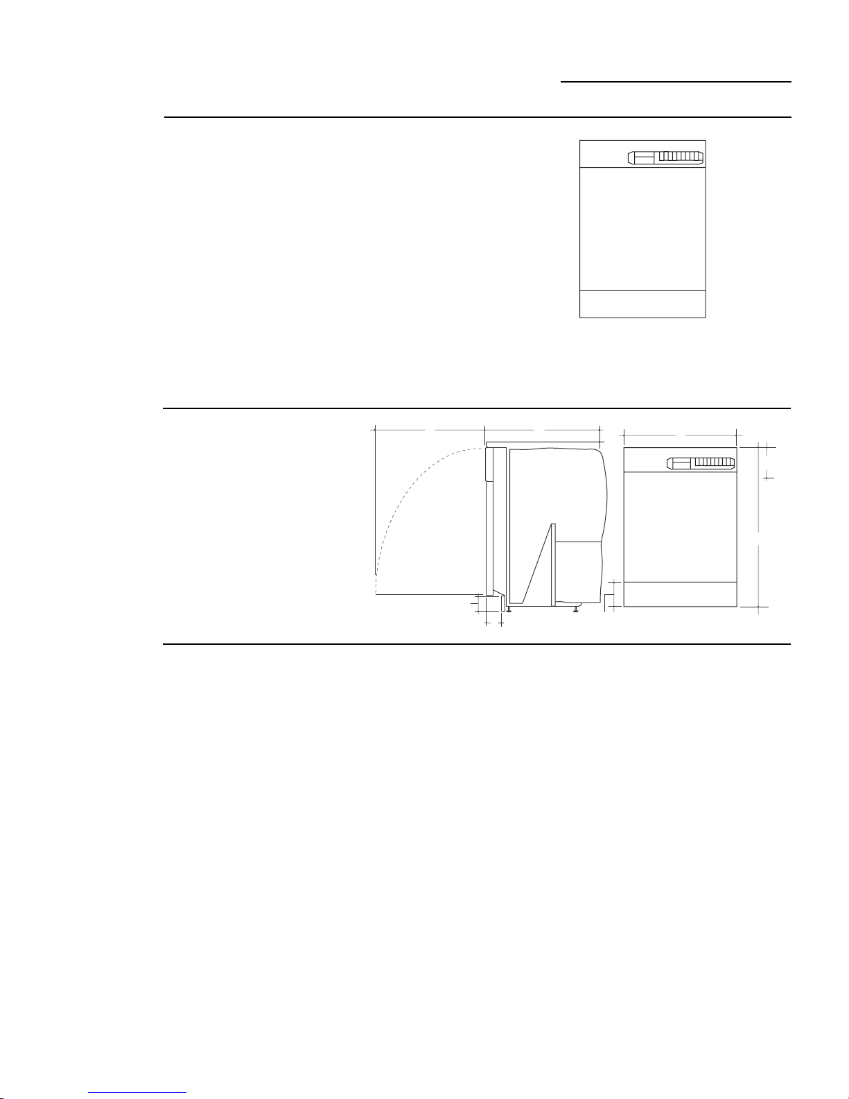
A – 34” Min. adjustable
to 35” max.
B – 23-5/8”
C – 23-1/2” total depth
D – 4” max., 2-7/8” min.
E – 5” escutcheon height
F – Adjustable, to 3-1/4”
G – 25-1/4” from cabinets
face (depending on depth
of cabinets)
Advance
Planning
• The black and white models may be covered
with custom decorative door panels of wood
or other materials to match cabinetry. See
“Optional Trim Kits,” page 4.
• The stainless steel model does not accept
custom panels.
• A custom toekick can be installed to match
cabinet toekick material. A continuous
toekick may be installed to form an
unbroken line at floor level.
– A continuous toekick should be installed
in such a manner that it can be removed if
service is required.
• Tub flange trim is supplied to conceal any
slight gap between the dishwasher and
adjacent cabinetry.
• These dishwashers may be installed beneath
countertops of stone or other materials that
will not accept screws. No trim kit required.
See “Secure dishwasher to countertop or
adjacent cabinetry”, page 14.
3
Design Information
Stainless Steel Interior Dishwashers
Standard
installation
in 24” deep
cabinets
Optional
Trim Kits
• Install in standard 24” deep cabinets:
– The dishwasher door will be flush with the
front face of adjacent cabinetry.
• With a 3/4” thick custom door panel in
place, the exterior is trimless and fits flush
to adjacent cabinetry.
• ZPF25W, white or ZPF25B, black custom
panel kit – Provides for the installation of a
1/4” thick custom door panel. See page 16
for installation instructions.
• ZPF75W, white or ZPF75B, black custom
panel kit – Provides for a trimless appearance using a 3/4” thick custom door panel.
See page 19 for installation instructions.
Cabinet
Depth
24"
Cabinet
Resting
Against Wall
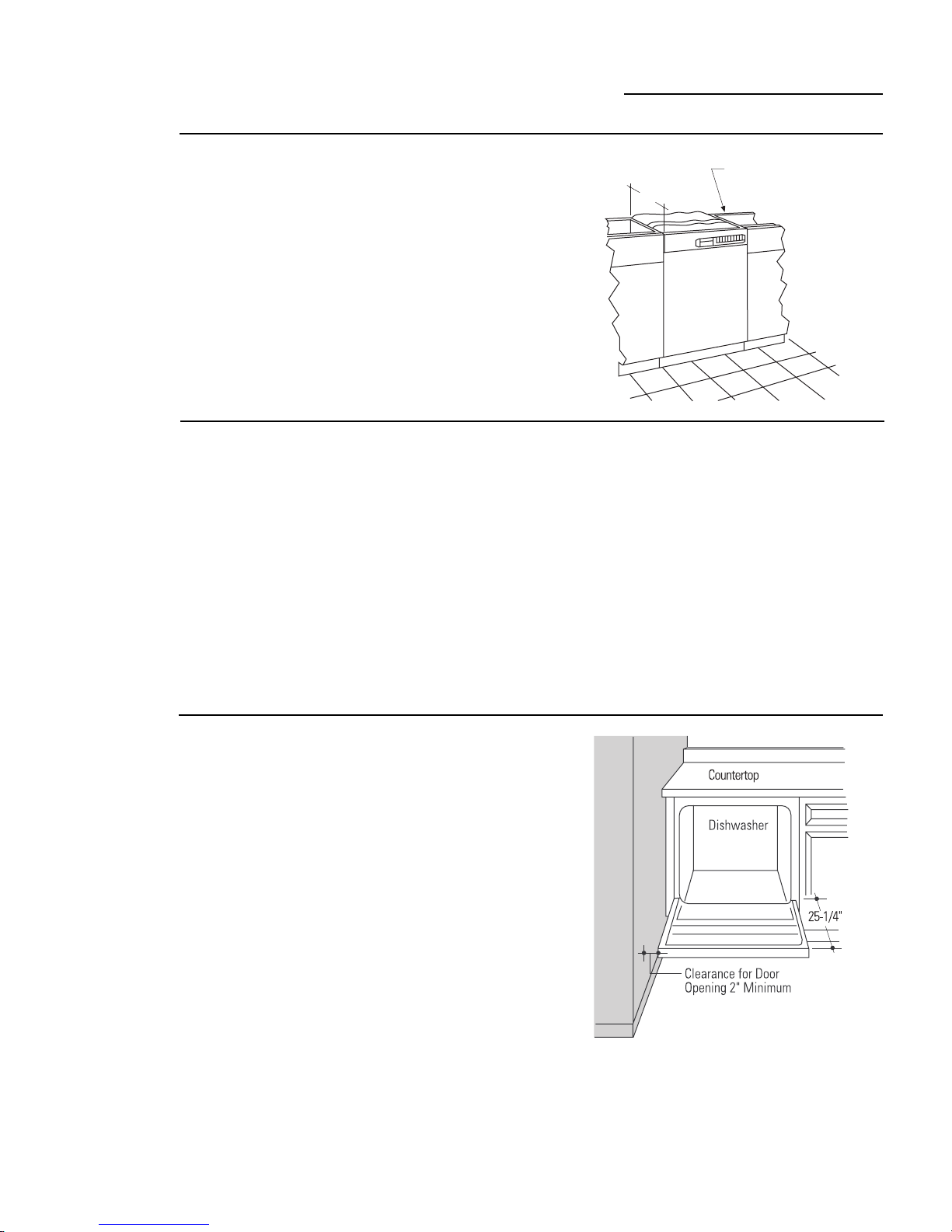
Corner
installation
• For a corner installation, allow 2” clearance
between dishwasher and adjacent cabinet
or wall.
• Dishwasher must be placed no more than
10 feet from sink for proper drainage.
4
Installation Information
Stainless Steel Interior Dishwashers
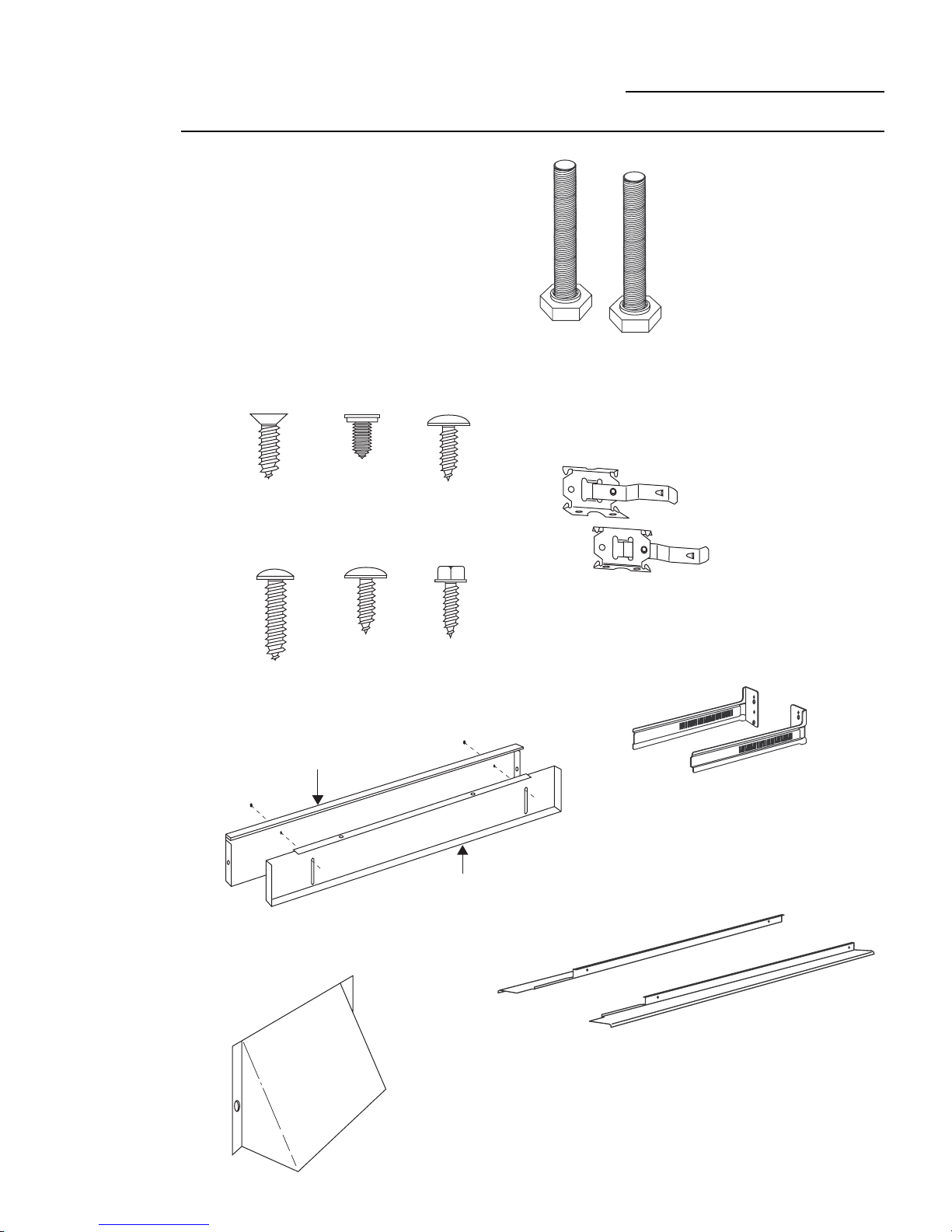
Parts
Supplied
Remove the hardware accessory bag and
other parts from inside or taped to the
outside of the dishwasher. Check contents
against drawings to insure that all parts are
included.
■■ 2 toekick slides
■■ 2 toekick support brackets
■■ 2 side trim pieces
■■ 2-piece toekick
■■ 16 Screws (see illustration)
■■ 2 leveling legs
■■ Junction box
Screw B
Screw A
(2) Countertop
Mounting
Screws
(4) Side Trim
Screws
Screw C
(4) Toekick
Bracket
Screws
2 Leveling Legs
Left and Right Side
Toekick Support Brackets
Screw D
(2) Cabinet
Mounting
Screws
Front Toekick Panel
Screw E
(2) Toekick
Slide Screws-
Color Matched
2 Piece Toekick
Screw F
(2) Junction Box
Screws
Inner Toekick Panel
Junction Box
Left and Right Side
Toekick Slides
2 Side Trim Pieces
5
Installation Preparation
Stainless Steel Interior Dishwasher
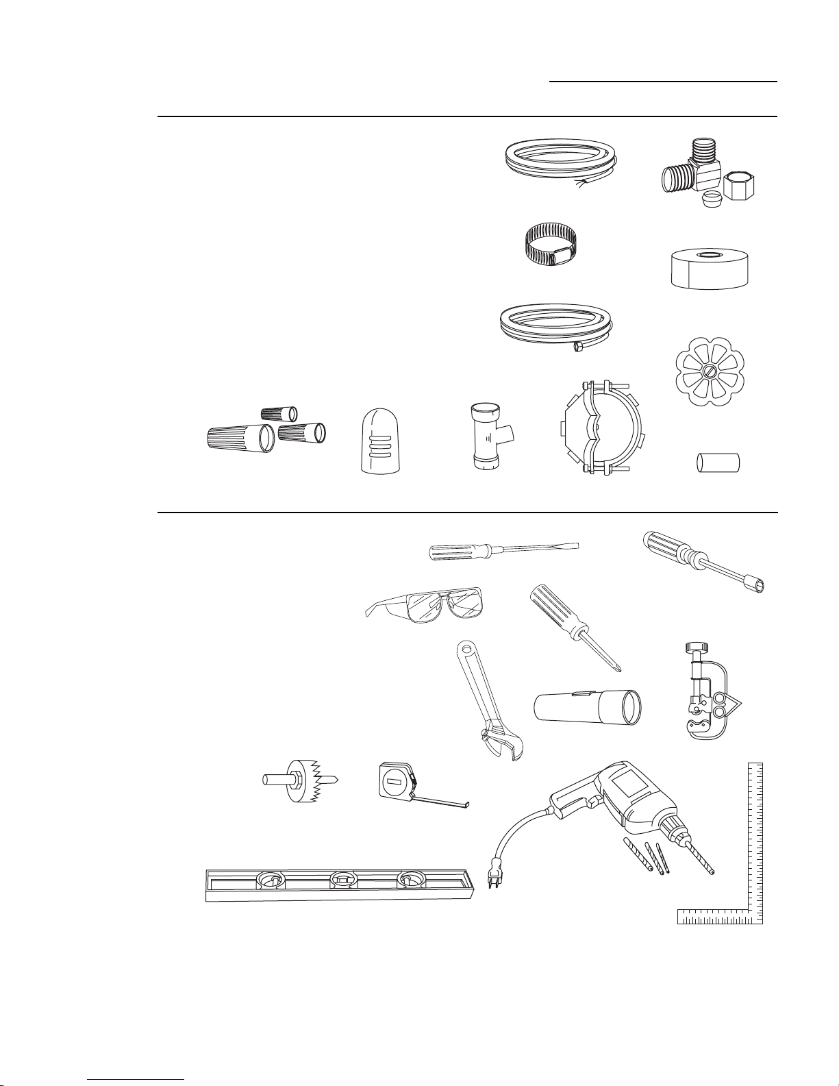
Materials You
Will Need:
(not supplied)
Tools you
Will Need:
(Not Supplied)
■■ 90° elbow (3/8" NPT external thread on one end and opposite
end to fit hot water supply line)
■■ Thread seal tape
■■ UL listed wire nuts (3)
For new installations only:
■■ Air gap for drain hose, if required
■■ Waste tee for house plumbing, if applicable
■■ Electrical cable or power cord, if applicable
■■ Screw type hose clamps
■■ Strain relief for electrical connection
■■ Hand shut-off valve (recommended)
■■ Water line 3/8" O.D. min. copper or 1/2" O.D. min plastic.
Air
Gap
Wire Nuts
■■ Phillips head and flat blade screwdrivers
■■ Adjustable wrench (6")
■■ 3/8", 5/16" and 1/4" nut drivers
■■ Level
■■ Carpenter’s square
■■ Measuring tape
■■ Safety glasses
■■ Flashlight
Safety Glasses
Electrical Cable
or Power Cord
Screw Type Clamps
Hot Water Line
Waste
Tee
Flat Blade Screwdriver
Strain Relief
Phillips Head
Screwdriver
90° Elbow
Thread Seal
Tape
Shut-Off
Valve
Coupler
Nut Driver
For new installation only:
■■ Tubing cutter
■■ Drill and appropriate bits
■■ Hole saw set
Level
Hole
Saw Set
Adjustable
Wrench
Measuring Tape
Tubing
Cutter
Flashlight
Drill
and Bits
Square
6

Installation Preparation
34" to 35"
Underside
of Countertop
to Floor
This Wall Area
must be Free of
Pipes or Wires
23-5/8" Min.
24" Max
1-3/4"
24"
Min.
6"
6"
1-1/2"
Dia.
Hole
1-3/4"
2" from Floor
Cabinet Face
Hot
Shut-off Valve
Left
Side Entry
Approx. 30"
from Wall
Right Side Entry
Approx. 40"
from Wall
Stainless Steel Interior Dishwasher
Prepare
the
Opening
Water
Supply
• The rough cabinet opening must be 24”
min. deep, 23-5/8” min. to 24” max. wide.
The opening height should be 34” min.
and 35” max.
• The opening should be free of extraneous
pipes and wires.
• Hot water line may enter from either side,
from the rear, or from the floor within the
shaded area shown.
• Turn off water supply.
• Cut a hole approximately 1-1/2” in diameter to admit water line. Access hole must
be round and smooth.
• Install a hand shut-off valve in the supply
line in an accessible location, such as under
the sink. (The shut-off valve is optional, but
recommended and may be required by
local codes.)
• Install the hot water line, using no less than
3/8” O.D. copper tubing or 1/2” O.D.
plastic tubing.
• The water line must be long enough to
form a smooth natural loop with no sharp
bends or kinks between the cutout entry
and fill valve location, centered at the front
of the dishwasher.
• Adjust the water heater to deliver 120°F
min. water temperature.
• The water pressure of the hot water supply
line must be 20 to 120 psi.
• Before connecting, flush water line to clean
out debris.
7
Installation Preparation
Stainless Steel Interior Dishwashers
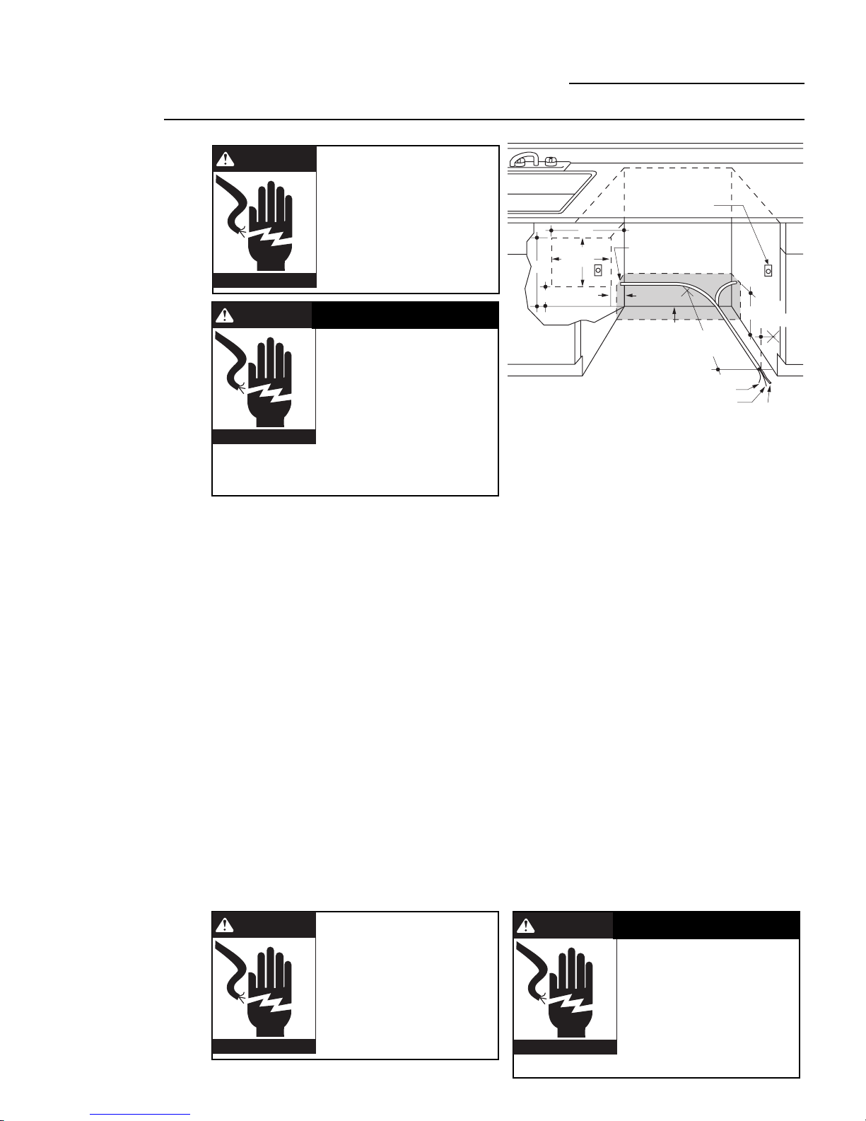
Power
Supply
WARNING
FOR PERSONAL SAFETY:
REMOVE HOUSE FUSE OR OPEN
CIRCUIT BREAKER BEFORE BEGINNING
INSTALLATION.
DO NOT USE AN EXTENSION CORD OR
ADAPTER PLUG WITH THIS APPLIANCE.
FOLLOW NATIONAL ELECTRICAL
CODES OR PREVAILING LOCAL CODES
AND ORDINANCES.
AVERTISSEMENT
SÉCURITÉ
IL FAUT ENLEVER LE FUSIBLE DE LA
MAISON OU OUVRIR LE DISJONCTEUR
AVANT DE COMMENCER
L’INSTALLATION.
IL NE FAUT PAS UTILISER DE
RALLONGE NI D’ADAPTATEUR DE
FICHE AVEC CET APPAREIL. IL FAUT RESPECTER TOUS LES
CODES D’ÉLECTRICITÉ NATIONAUX OU LES CODES ET
RÈGLEMENTS LOCAUX EN VIGUEUR.
Electrical Requirements:
These dishwashers must be supplied with a
120 volt, 60 Hz power supply with an individual, properly grounded branch circuit,
protected by a 15 or 20 amp fuse or circuit
breaker or time delay fuse.
• Wiring must be 2 wire with ground.
• If electrical supply does not meet the above
requirements, call a licensed electrician
before proceeding.
Grounding Instructions:
This appliance must be either connected to a
grounded-metal permanent wiring system, or
an equipment-grounding conductor must be
run with the circuit conductors and be
connected to the equipment-grounding
terminal or lead on the appliance.
Alternate
Receptacle
Location
18"
1-1/2" Dia. Hole (Max.)
6"
2"
from Wall
24"
Ground
Black
2"
Cabinet
White
3"
from
18"
6"
Receptacle
Location
Area
Cabinet Preparation & Wiring:
• Wiring may enter from either side, the rear,
or from the floor within the shaded area
shown.
• Cut hole 1-1/2” max. diameter within the
shaded area to admit the electrical cable or
power cord. The hole must be free of sharp
edges. If the cabinet wall partition is metal,
the edge of the hole must be covered with a
rubber protector.
Electrical Connections:
The electrical connection is on the right side
of the dishwasher.
• For cable direct connections, the cable must
be routed as illustrated. The cable must
extend forward a minimum of 24” from the
rear wall.
• For power cord connections, install a
3-prong type receptacle in the rear wall of
sink cabinet next to the dishwasher. Install
the receptable at least 6” and not more than
18” from the dishwasher opening. The
receptacle should be at least 6” and not
more than 18” off the floor.
• Allow approximately 3” between cable and
adjacent cabinetry.
WARNING
THE IMPROPER CONNECTION OF THE
EQUIPMENT - GROUNDING
CONDUCTOR CAN RESULT IN A RISK
OF ELECTRIC SHOCK. CHECK WITH A
QUALIFIED ELECTRICIAN OR SERVICE
REPRESENTATIVE IF YOU ARE IN
DOUBT WHETHER THE APPLIANCE IS
PROPERLY GROUNDED.
AVERTISSEMENT
LE MAUVAIS BRANCHEMENT DU
CONNECTEUR DE MISE À LA TERRE DE
L’ÉQUIPEMENT PEUT CAUSER UN
RISQUE D’ÉLECTROCUTION. EN CAS DE
DOUTE SUR LA MISE À LA TERRE DE
L’APPAREIL, CONSULTER UN
ÉLECTRICIEN QUALIFIÉ OU UN
PRÉPOSÉ DE SERVICE.
8
 Loading...