

GE MONOGRAM ZBD0700, Monogram ZBD0710, Monogram ZBD6880, Monogram ZBD6890, Monogram ZBD6800 Installation Instructions Manual
Page 1

If you have questions, call 800.626.2000 or visit our website at: www.monogram.com
Monogram.
®
Installation
Instructions
Built-In Dishwashers
ZBD6800
ZBD6880
ZBD6890*
ZBD0700*
ZBD0710
Design Guide with
Installation Instructions
*For ZBD6890 and ZBD0700 also refer
to the instructions provided on the
template packed with that model.
Page 2

Safety Information
2
CONTENTS
Installation Preparation
Parts Supplied..............................................................................3
Materials You Will Need ............................................................3
Tools You Will Need ....................................................................3
Models Available ........................................................................4
Advance Planning ......................................................................4
Prepare Dishwasher Enclosure ................................................4
Drain Requirements ....................................................................5
Prepare Electrical Wiring ..........................................................6
Prepare Hot Water Line..............................................................7
Installation Instructions
Step 1, Check Door Balance......................................................7
Step 2, Remove Wood Base, Install Leveling Legs ..............8
Step 3, Remove ToeKick ............................................................8
Step 4, Install Power Cord ........................................................8
Step 5, Install 90° Elbow ............................................................8
Step 6, Position Water Line and House Wiring......................9
Step 7, Install Drain Hose, Guide Through Cabinet ..............9
Step 8, Slide Dishwasher Partially Into Cabinet ....................9
Step 9, Install Trim Pieces..........................................................9
Step 10, Position Dishwasher Under Countertop ................10
Step 11, Level Dishwasher ......................................................11
Step 12, Secure Dishwasher To Cabinet ..............................12
Step 13, Connect Water Supply ..............................................13
Step 14, Connect Drain Line ....................................................13
Step 15, Connect Power Supply..............................................14
Step 16, Pre-Test Check List....................................................14
Step 17, Dishwasher Wet Test ................................................15
Step 18, Replace Toekick ........................................................15
Step 19, Literature ....................................................................15
Custom Panel Dimensions
Custom Panel for Models ZBD6890, ZBD0700......................15
BEFORE YOU BEGIN
Read these instructions completely and carefully.
•
IMPORTANT — Save these instructions for
local inspector’s use. Observe all governing codes and
ordinances.
• Note to Installer — Be sure to leave these
instructions with the Consumer.
• Note to Consumer — Keep these instructions
with your Owner’s Manual for future reference.
• Skill Level — Installation of this dishwasher requires
basic mechanical and electrical skills. Proper installation
is the responsibility of the installer. Product failure due
to improper installation is not covered under the GE
Appliance Warranty.
• Completion Time — 1 to 3 Hours.
New installations require more time than replacement
installations.
•
IMPORTANT — The dishwasher MUST
be installed to allow for future removal from the
enclosure if service is required.
• If you received a damaged dishwasher, you should
immediately contact your dealer or builder.
READ CAREFULLY.
KEEP THESE INSTRUCTIONS.
FOR YOUR SAFETY
Read and observe all CAUTION and WARNINGS shown
throughout these instructions.
While performing installations described in this booklet,
gloves, safety glasses or goggles should be worn.
For Monogram local service in your area, 1.800.444.1845.
For Monogram service in Canada 1.888.880.3030
For Monogram Parts and Accessories, call 1.800.626.2002.
Page 3
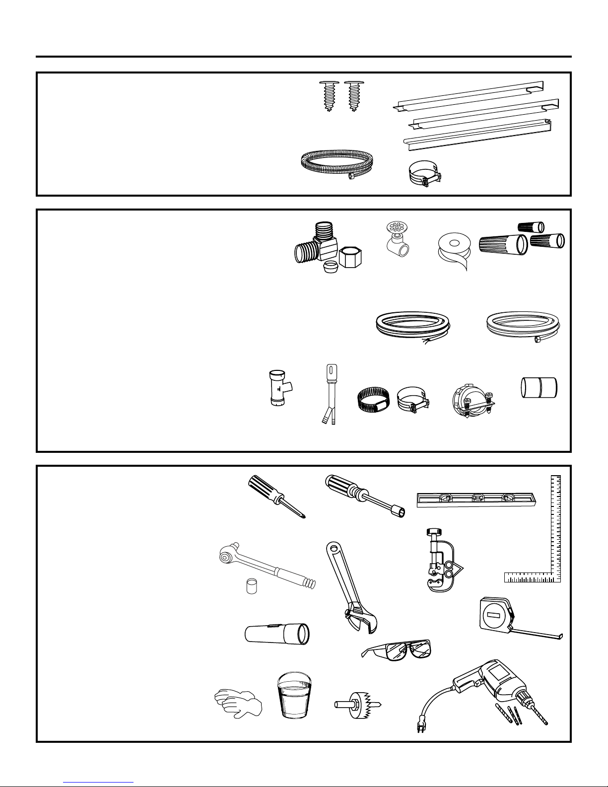
TOOLS YOU WILL NEED:
Phillips head screwdriver
5/16" and 1/4" nutdriver
6" Adjustable wrench
Level
Carpenters square
Measuring tape
Safety glasses
Flashlight
Bucket to catch water when flushing the line
15/16" socket (optional for skid removal)
Gloves
For New Installations Only:
Tubing cutter
Drill and appropriate bits
Hole saw set
MATERIALS YOU WILL NEED:
Ferrule, compression nut and 90° Elbow (3/8" NPT
external thread on one end, opposite end sized to fit
water supply)
Thread seal tape
UL Listed wire nuts (3)
Materials For New Installations Only:
Air gap for drain hose, if required
Waste tee for house plumbing, if applicable
Electrical cable or power cord, if applicable
Screw type hose clamps
Strain relief for electrical connection
Hand shut-off valve
Water line 3/8" min. copper
Coupler for extending drain line, if applicable
PARTS SUPPLIED:
Two #8-18 x 5/8" Phillips special head screws, to secure
dishwasher to underside of countertop or sides of
cabinets. (Taped to top side of dishwasher.)
Side and top trim pieces (on some models)
Template with mounting hardware (not shown)
for Model ZBD6890 Only
Drain Hose and Hose Clamp
Installation Preparation
3
Wire Nuts (3)
Hot Water line
Screw Type
Hose Clamps
Coupler
Hand
Shut-Off
Valve
#8 Phillips Special Head
Screws 5/8" Long
Hole Saw Set
Measuring Tape
Tubing Cutter
Drill and Bits
Phillips
Head
Screwdriver
15/16" Socket
1/4"
and 5/16"
Nutdriver
Safety Glasses
6" Adjustable
Wrench
Bucket
Flashlight
Gloves
Carpenters
Square
Level
Thread
Seal Tape
Air Gap
Strain Relief
Drain Hose
Hose Clamp
90° Elbow,
Ferrule and
Compression Nut
Electrical Cable
(or Power Cord, if applicable)
Waste Tee
Trim Pieces
(on some models)
Page 4
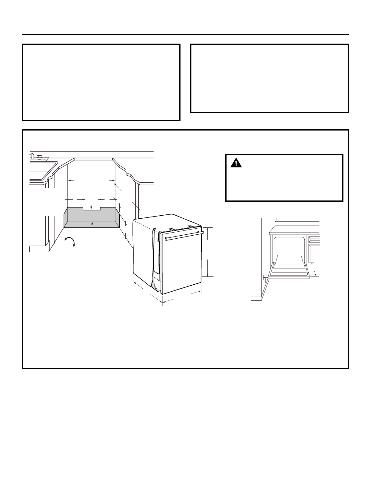
PREPARE DISHWASHER ENCLOSURE
• The rough cabinet opening must be at least 24" deep,
24" wide and approximately 34-1/2" high from floor to
underside of the countertop.
• Plumbing and electrical service must enter the shaded
area.
• The dishwasher must be installed so that drain hose is
no more than 10 feet in length for proper drainage.
WARNING
To reduce the risk of electric shock, fire,
or injury to persons, the installer must
ensure that the dishwasher is completely
enclosed at the time of installation.
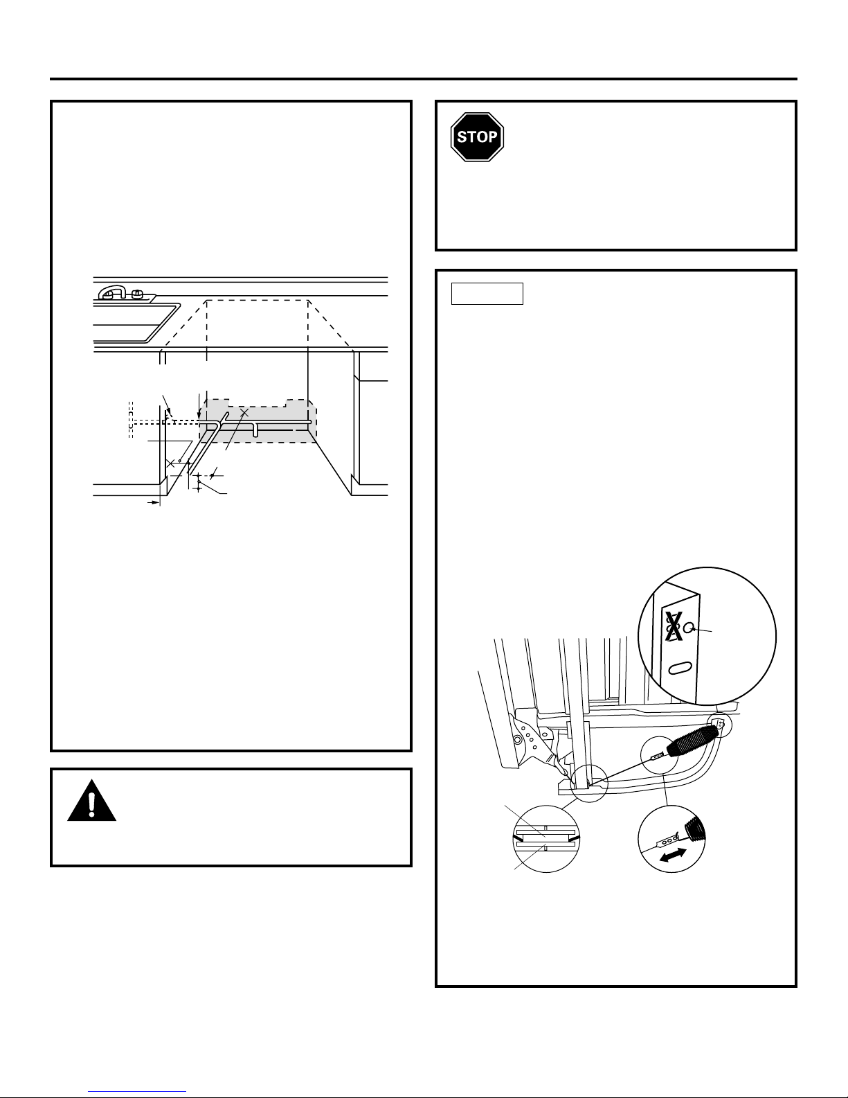
Clearance for Door
Opening 2" Minimum
Countertop
Dishwasher
28-3/8"
Figure B
Installation Preparation
CLEARANCES: When installed
into a corner, allow 2" min.
clearance between dishwasher
and adjacent cabinet, wall or
other appliances. Allow 28-3/8"
min. clearance from the front of
the dishwasher for door
opening (Figure B).
4
DISHWASHER MODELS
ZBD0710 SS, Stainless Steel
ZBD6880 SS, Stainless Steel
ZBD6800 BB, Black
ZBD6800 WW, White
ZBD6890 Requires a 3/4" custom panel and handle
ZBD0700 Requires a 3/4" custom panel and handle
ADVANCE PLANNING
• These dishwashers are designed for versatility,
adaptable to virtually any installation.
• All models have a full length door without the
traditional access panel.
• These dishwashers may be installed beneath
countertops of stone or other materials that will not
accept screws. No trim kit required.
*Dishwasher models ZBD6890
and ZBD0700 require a 3/4”
thick custom panel and will be
24-3/4” deep.
Figure A
This Wall Area
must be Free of
34-1/2" Min.
Underside of
Countertop
to Floor
Pipes or wires
5" 5"
4"
4"
24"
Min.
6"
Cabinets
Square
and
Plumb
24" Min.
Floor MUST
be Even with
Room Floor
*24"
24"
34"
Adjustable
to 35"
Page 5
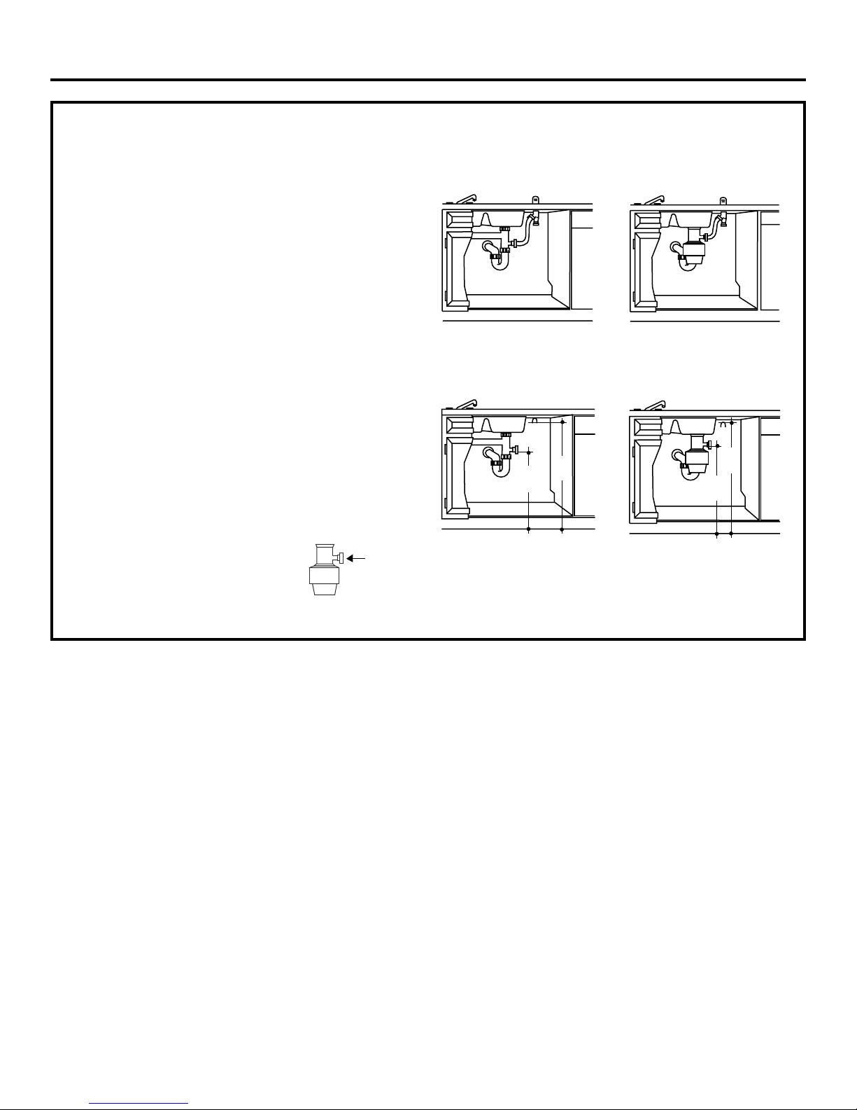
DRAIN REQUIREMENTS
• Follow local codes and ordinances.
• Do not exceed 10 feet distance to drain.
• Do not connect drain lines from other devices to the
dishwasher drain hose.
NOTE: An air gap must be used, if waste tee or disposer
connection is less than 18" above floor to prevent
siphoning.
DETERMINE DRAIN METHOD
The type of drain installation depends on the following
question.
Do local codes or ordinances require an air gap?
Is waste tee less than 18" above floor?
If the answer to either question is YES, Method 1 MUST
be used.
• If the answers are NO, either method may be used.
CABINET PREPARATION
• Drill a 1-1/2" dia. hole in the cabinet wall within the
shaded areas shown in Figure A for the drain hose
connection. The hole should be smooth with no
sharp edges.
Method 1—Air Gap with Waste Tee or Disposer
An air gap must be used when required by local codes and
ordinances. The air gap must be installed according to
manufacturers instructions.
Method 2—“High Drain Loop” with Waste Tee or
Disposer
Figure C
Figure D
32"
Min.
18"
Min.
32"
Min.
18"
Min.
IMPORTANT — When
connecting drain line to disposer,
check to be sure that drain plug has
been removed. DISHWASHER WILL
NOT DRAIN IF PLUG IS LEFT IN PLACE.
5
Installation Preparation
Remove
Hopper
Plug
Page 6
6
Installation Preparation
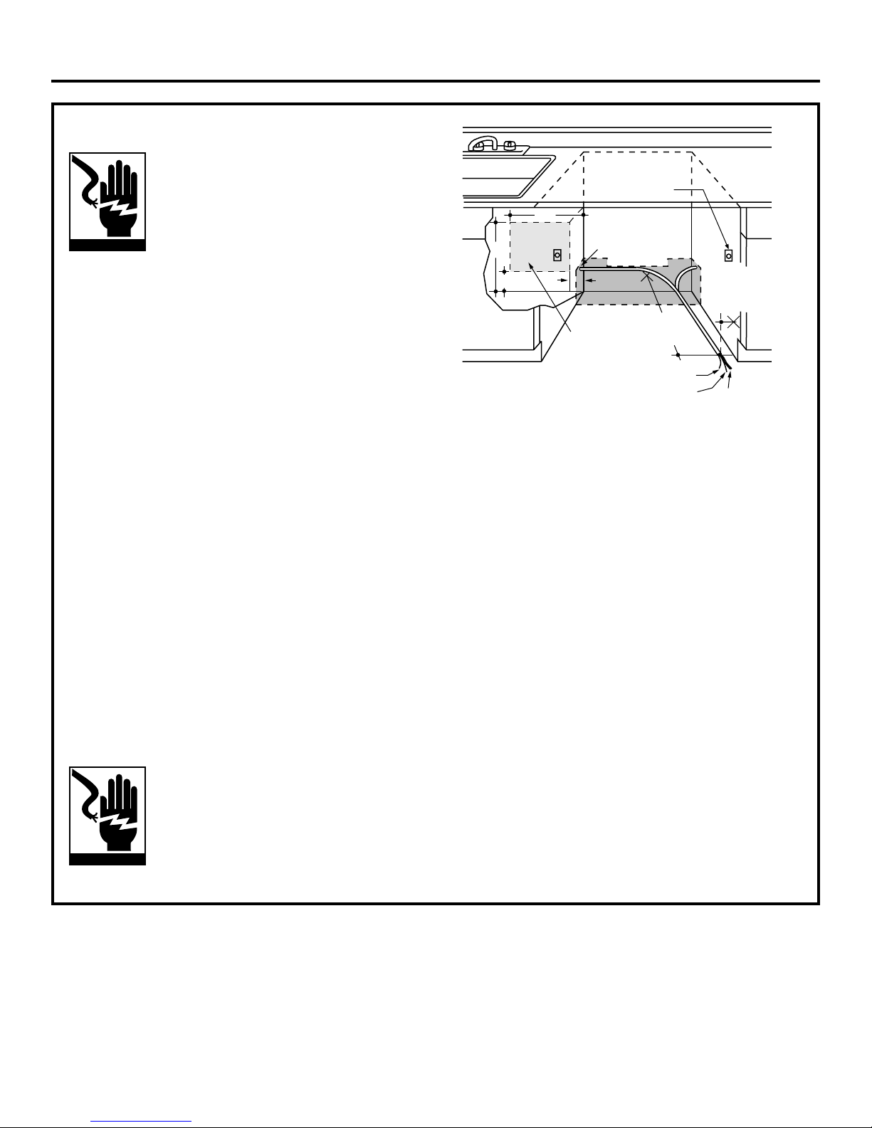
PREPARE ELECTRICAL WIRING
WARNING
FOR PERSONAL SAFETY: Remove house
fuse or open circuit breaker before
beginning installation. Do not use an
extension cord or adapter plug with this
appliance.
Electrical Requirements
• This appliance must be supplied with 120V, 60 Hz., and
connected to an individual properly grounded branch
circuit, protected by a 15 or 20 ampere circuit breaker
or time delay fuse.
• Wiring must be 2-wire with ground and rated for
75°C (176°F).
• If the electrical supply does not meet the above
requirements, call a licensed electrician before
proceeding.
Grounding Instructions—Cable Direct
This appliance must be connected to a grounded metal,
permanent wiring system, or an equipment grounding
conductor must be run with the circuit conductors and
be connected to the equipment grounding terminal or
lead on the appliance.
Grounding Instructions—Power Cord Models
This appliance must be grounded. In the event of a
malfunction or breakdown, grounding will reduce the
risk of electric shock by providing a path of least
resistance for electric current. This appliance is
equipped with a cord having an equipment grounding
conductor and a grounding plug. The plug must be
plugged into an appropriate outlet that is installed and
grounded in accordance with all local codes and
ordinances.
WARNING
The improper connection of the equipment
grounding conductor can result in a risk
of electric shock. Check with a qualified
electrician or service representative if you
are in doubt that the appliance is properly
grounded.
For models equipped with power cord: Do not modify
the plug provided with the appliance; if it will not fit the
outlet, have a proper outlet installed by a qualified
technician.
Cabinet Preparation and Wire Routing
• The wiring may enter the opening from either side,
rear or the floor within the shaded area.
• Cut a 1-1/2" max. dia. hole to admit the electrical
cable. Cable direct connections may pass through
the same hole as the drain hose and hot water line,
if convenient. If cabinet wall is metal, the hole edge
must be covered with a bushing.
• NOTE: Power cords with plug must pass through a
separate hole.
Electrical Connection to Dishwasher
Electrical connection is on the right front of
dishwasher.
• For cable direct connections the cable must be
routed as shown in Figure E. Cable must extend
a minimum of 24" from the rear wall.
• For power cord connections, install a 3-prong
grounding type receptacle in the sink cabinet rear
wall, 6" min. or 18" max. from the opening, 6" to 18"
above the floor.
Figure E
Alternate
Receptacle
Location
18"
18"
6"
6"
1-1/2" Dia.
Hole (Max.)
Receptacle
Location
Area
24"
from Wall
Ground
Black
3"
from
Cabinet
White
Page 7
PREPARE HOT WATER LINE
• The line may enter from either side, rear or floor
within the shaded area shown in Figure F.
• The line may pass through the same hole as the
electrical cable and drain hose. Or, cut an additional
1-1/2" dia. hole to accommodate the water line.
If power cord with plug is used, water line must
not pass through power cord hole.
Water Line Connection
• Turn off the water supply.
• Install a hand shut-off valve in an accessible location,
such as under the sink. (Optional, but strongly
recommended and may be required by local codes.)
• Water connection is on the left side of the dishwasher.
Install the hot water inlet line, using no less than 3/8"
O.D. copper tubing. Route the line as shown in Figure F
and extend forward at least 19" from rear wall.
• Adjust water heater for 120°F to 150°F temperature.
• Flush water line to clean out debris.
• The hot water supply line pressure must be 20-120 PSI.
Installation Instructions
7
CAUTION
Do not remove wood base until you are ready
to install the dishwasher. The dishwasher will tip over
when the door is opened if the wood base is removed.
BEFORE YOU BEGIN
Locate and set aside (for use in Step 12) the
2 Phillips special head screws wrapped with
yellow tape and stuck to the top or side of the
dishwasher. Remove drain hose from upper rack, if
it has not been pre-installed, and set aside for use in
Step 7.
Figure F
CHECK DOOR BALANCE
• With dishwasher on the wood skid, check the door
balance by opening and closing the door.
• If the door drops when released, increase the spring
tension. If the door rises when released, decrease
the tension.
NOTE: The addition of the custom panel on model
ZBD6890 will require exchange of the factory installed
springs. Use the heavy-duty springs provided. See the
custom panel template for additional instructions.
• Position the spring for increased or decreased
tension as required.
NOTE: Adjust both balance springs to the same
amount of tension to prevent excessive door
twisting during use.
TIP: If door does not open easily or falls too quickly,
check the spring cable routing. Check that the cable
is properly aligned on the pulley (as shown).
STEP 1
Figure G
Shut-off
Valve
Hot
2"
From
Cabinet
Cabinet Face
1-1/2" Dia.
Hole
19" From Wall
2" From Floor
Use This
Mounting
Hole
Pulley
Shoulder
Correct Spring
Cable Routing
Increase
Tension
Decrease
Tension
Page 8

REMOVE WOOD BASE,
INSTALL LEVELING LEGS
IMPORTANT — Do not kick off wood base! Damage
will occur.
• Move the dishwasher close to the installation location and lay it
on its back.
• Remove the four leveling legs on the underside of the
wood base with an adjustable wrench or 15/16" socket.
• Discard base.
• Screw leveling legs back into the dishwasher frame,
approximately 1/4" from frame as shown.
STEP 2
REMOVE TOEKICK
• Remove the two toekick screws.
STEP 3
8
T
oekick
Remove 2
Toekick Screws
Installation Instructions
Figure H
Approx.
1/4"
Figure J
INSTALL POWER CORD
Use Power Cord Kit WX09X70910 available for purchase from an
authorized GE Appliances dealer.
Skip this step if dishwasher will be direct wired or has a
factory installed power cord.
The power cord and connections must comply with the National
Electrical Code, Section 422 and/or local codes and ordinances.
• Maximum power cord length is 4 feet beyond the back of the
dishwasher.
• Connect incoming power cord white (or ribbed) to dishwasher
white, black (or smooth) to black and ground to dishwasher
green wire. Use UL listed wire nuts of appropriate size.
• Replace junction box cover. Be sure wires are not pinched
under the cover.
STEP 4
Figure K
INSTALL 90° ELBOW
• Wrap 90° elbow with thread seal tape.
• Install a 90° elbow onto the water valve.
• Do not overtighten 90° elbow, water valve bracket could bend
or water valve fitting could break.
• Position the end of the elbow to face the rear of the dishwasher
.
STEP 5
Figure L
Remove
Junction Box
Cover
C
Check That White, Black and
Green Dishwasher Wires Are Threaded
Thru Small Hole in Bracket
A
B
Insert Power
Cord Wires Thru
Strain Relief
and Tighten
Ground
Use UL Listed
Wire Nuts
White
Black
D
Front of Dishwasher
Water Valve
Bracket
90°
Elbow
Fill
Hose
Thread
Seal Tape
Page 9
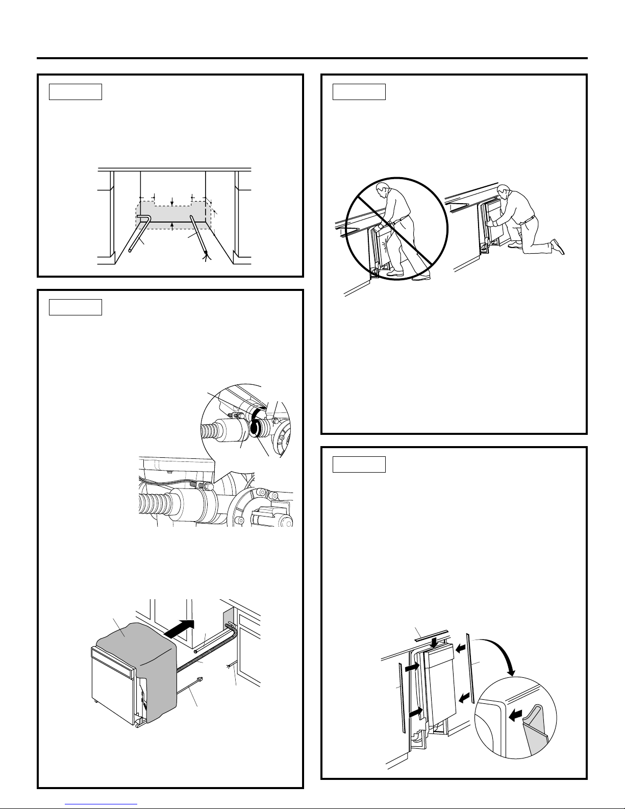
INSTALL DRAIN HOSE,
GUIDE THROUGH CABINET
• Remove tape and wire tie holding the clamp to the
drain hose. Be careful not to damage the drain hose.
• Stand the dishwasher upright.
• Slip the supplied
hose clamp over
the large end of
the hose. Do not
tighten.
• Push hose over the drain outlet on the back side of
the dishwasher. See illustration. Push the hose over
the outlet and against the shoulder stop.
• Tighten the hose clamp with a 1/4" nut driver.
• Position the dishwasher in front of the opening.
Insert drain hose into the cabinet side. If power cord
is used, guide the end through a separate hole.
STEP 7
INSTALL TRIM PIECES
Skip this step if trim is not supplied with the
dishwasher.
• Locate trim strips inside dishwasher.
• Press trim onto the tub flange on each side. Start
with the top edge, pressing on as you move towards
the bottom.
• Press the two top trim pieces on each side of
the latch.
• Open and close the door to check that trim does not
bind and does not interfere with door latch.
STEP 9
POSITION WATER LINE
AND HOUSING WIRING
• Position water supply line and house wiring on the
floor of the opening to avoid interference with base
of dishwasher and components under dishwasher.
STEP 6
9
Figure Q
Trim Strip
Trim
Strip
Trim
Strip
Water
Line
House
Wiring
5"
5"
4"
6"
4"
Installation Instructions
Figure M
SLIDE DISHWASHER
PARTIALLY INTO CABINET
DO NOT PUSH AGAINST FRONT PANEL WITH KNEES.
DAMAGE WILL OCCUR.
• Slide dishwasher into the opening a few inches
at a time.
• As you proceed, pull the drain hose through the
opening under the sink. Stop pushing when the
dishwasher is a few inches forward of adjacent
cabinetry.
• Make sure drain hose is not kinked under the
dishwasher and there is no interference with the
water line and wiring or any other component.
STEP 8
Figure P
Figure O
Figure N
Drain
Outlet
Hose
Clamp
Shoulder
Stop
Flapper
Valve—Do
Not Remove
Reposition Dishwasher
by Grasping Both
Do Not Push Against
Front Door Panel With
Knee. Damage to The
Door Panel Will Occur.
Sides With Hands
Insulation
Blanket
Water
Line
Drain
Hose
Power Cord
(If Used)
House
Wiring
Page 10
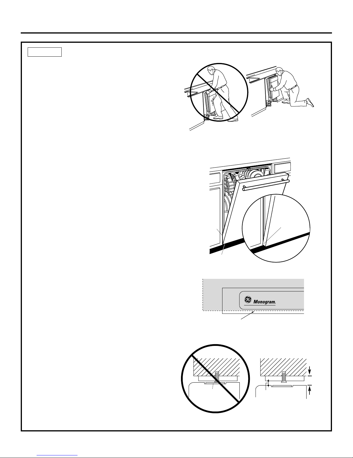
POSITION DISHWASHER UNDER COUNTERTOP
STEP 10
10
• Push the dishwasher into the cabinet.
• Push at the sides with your hands. Do not use your
knee against the door since door damage will occur.
• Check that the tub insulation blanket does not get
“bunched-up” or interfere with the springs as you
slide it into the cabinet.
• Center the dishwasher in the opening.
• Check that the edges of the dishwasher door are
behind the cabinet frame and aligned with the front
face of the cabinet as shown.
• Carefully open and close the door to ensure that the
door panel does not catch or rub on the cabinet frame.
• If the door catches or rubs on the frame, reposition
and/or level the unit (see Step 11) until the door moves
freely and does not contact the cabinet frame.
The controls are designed to be hidden by your
countertop. Align the dishwasher as shown in Figure T.
NOTE: If the drain hose gets trapped between the wall
and the back side of the dishwasher, it can prevent the
dishwasher from sliding all the way back into the
cabinet opening, and thus preventing a flush fit with
the kitchen cabinet panels.
TIP: For best appearance installations of custom panel
models, it may be necessary to cut off the back panel
of the tub insulation blanket so that the dishwasher
door panel can be aligned flush with the kitchen
cabinet panels.
The leveling legs can be used to increase or decrease
the amount of gap between the controls and the
countertop affecting the visibility of the controls.
Leave a 1/2" minimum gap between the underside
of the countertop and the top of the dishwasher
door (see Figure V).
IMPORTANT — Leave a 1/2" minimum
gap between the controls and the underside of the
countertop to prevent condensation and damage to the
control panel from screwheads.
NOTE: If this dishwasher is replacing an existing
dishwasher, the old countertop bracket screw holes
may not be in the correct position to accept a top
control model. New holes may be required.
Control Panel
Countertop
Minimum 1/2" Gap
for Clearance
Countertop
1/2" min.
Figure U
Figure V
Top View
Controls Hidden
by Countertop
Installation Instructions
Figure S
Figure T
Figure R
Do Not Push Against
Front Door Panel With
Knee. Damage to The
Door Panel Will Occur.
Door
Fits and
Swings
Back
Behind
Cabinet
Frame
Correct
Alignment
Reposition Dishwasher
by Grasping Both
Sides With Hands
Door Catches
on Cabinet Frame
Incorrect
Alignment
Page 11

LEVEL DISHWASHER
IMPORTANT — Dishwasher must be level
for proper dish rack operation and wash performance.
• Place level on door
and rack track inside
the tub as shown to
check that the
dishwasher is level.
• Level the
dishwasher by
adjusting the
four leveling legs
individually.
• Make sure 1/2"
minimum gap is
maintained (see
Figure V).
• If adjustment to the right rear leveling leg is required,
gain access by loosening junction box bracket screw
(through the access hole) and rotate bracket
clockwise.
TIP: Pull lower rack out, about halfway. Check to
be sure the rack does not roll forward or back into
dishwasher. If the rack rolls in either direction, the
dishwasher must be leveled again.
• If the door hits the tub, the dishwasher is not installed
correctly. Adjust leveling legs to align door to tub.
STEP 11
11
Installation Instructions
Figure W
Figure X
Check
Level
Front
to Back
Check
Level
Side
To Side
Access Hole
Turn Legs
to Adjust
Page 12

12
Installation Instructions
SECURE DISHWASHER TO CABINET
STEP 12
The dishwasher must be secured to the countertop or
the cabinet sides. When countertops are made of wood,
use Method 1. When countertops are granite or other
materials that will not accept screws, use Method 2 to
secure dishwasher at the sides.
IMPORTANT — After leveling, verify that
the dishwasher is still in the correct position shown in
Step 10.
IMPORTANT — Drive screws straight and
flush. Protruding screw heads will scratch the top or
sides of the control panel and can interfere with door
closing.
Method 1—Secure dishwasher to wood
countertop
• Fasten the dishwasher to the underside of the
countertop with 2 Phillips screws provided.
Method 2—Secure dishwasher with side
mounting brackets
• Remove plug buttons (one on each side).
• Install screw through the hole in the side of the
dishwasher and into the adjacent cabinet.
Reinstall plug buttons.
Both Methods—Maintain 1/2" Gap
Figure Y
Figure AA
Figure Z
Figure Y
1/2” Min.
Gap
Figure BB
Side Mounting
Brackets
Countertop
Mounting
Tub
Frame
Brackets
Brackets
Stone Countertop
Side Mounting Brackets
Wood Countertop
Plug Buttons
Screws
Page 13

13
Installation Instructions
CONNECT DRAIN LINE
FOLLOW ALL LOCAL CODES AND ORDINANCES.
The drain hose molded end will fit 5/8" or 1" diameter
connections on the air gap, waste tee or disposer. Cut
on the marked line as required for your installation.
• If a longer drain hose is required, add up to 42" of
length for a total of 10 ft. to the factory installed hose.
Use 5/8" or 7/8" inside diameter hose and a coupler to
connect the two hose ends. Secure the connection
with hose clamps.
• Secure the drain hose to the air gap, waste tee or
disposer with clamps.
NOTE: TOTAL DRAIN HOSE LENGTH MUST NOT EXCEED
10 FEET FOR PROPER DRAIN OPERATION.
DRAIN LINE INSTALLATION
• Connect drain line to air gap, waste tee or disposer
using either previously determined method.
Method 1—Air gap with waste tee or disposer
Method 2—“High drain loop” with waste tee or
disposer
IMPORTANT — When
connecting drain line to disposer,
check to be sure that drain plug has
been removed. DISHWASHER WILL
NOT DRAIN IF PLUG IS LEFT IN PLACE.
TIP: Avoid unnecessary service call charges. Always
be sure disposer drain plug has been removed before
attaching dishwasher drain hose to the disposer.
STEP 14
CONNECT WATER SUPPLY
Connect water supply line to 90° elbow.
• Slide compression nut, then ferrule over end of
water line.
• Insert water line into 90° elbow.
• Slide ferrule against elbow and secure with
compression nut.
IMPORTANT — Check to be sure that door
spring does not rub or contact the fill hose or water supply
line. Test by opening and closing the door. Re-route the
lines if a rubbing noise or interference occurs.
STEP 13
90° Elbow
Ferrule
90° Elbow
Compression Nut
Door Spring
Hot Water
Supply Line
Figure CC
Figure DD
Figure EE
Figure FF
Waste Tee Installation Disposer Installation
Figure GG
Fasten to underside
of countertop
32"
Min.
18"
Min.
Fasten to underside
of countertop
32"
Min.
18"
Min.
Disposer InstallationWaste Tee Installation
Remove
Hopper
Plug
Cutting Line
1"
5/8"
IMPORTANT: Do not cut corrugated
portion of hose
Coupler
Hose Clamp
Hose Clamp
Page 14

14
Installation Instructions
PRE-TEST CHECK LIST
Review this list after installing your dishwasher to
avoid charges for a service call that is not covered
by your warranty.
Check to be sure power is OFF.
Open door and remove all foam and paper
packaging.
Locate the Owner’s Manual in the literature
package.
Read the Owner’s Manual for operating instructions.
Check door opening and closing. If door does not
open and close freely or tends to fall, check spring
cable routing and spring adjustments. See Step 1.
Check to be sure that wiring is secure under the
dishwasher, not pinched or in contact with door
springs or other components. See Steps 8 and 10.
Check door alignment with tub. If door hits tub,
level dishwasher. See Step 11.
Pull lower rack out, about half way. Check to be
sure it does not roll back or forward on the door.
If the rack moves, adjust leveling legs. See Step 11.
Check door alignment with cabinet. If door hits
cabinet, reposition or relevel dishwasher. See
Steps 10, 11 and 12.
Check that door spring does not contact water line,
fill hose, wiring or other components. See Step 13.
Verify water supply and drain lines are not kinked
or in contact with other components. Contact with
motor or dishwasher frame could cause noise.
See Steps 6 and 8.
Turn on the sink hot water faucet and verify water
temperature. Incoming water temperature must
be between 120°F and 150°F. A minimum of 120°F
temperature is required for best wash performance.
See “Prepare Hot Water Line,” page 7.
Add 2 quarts of water to the bottom of the
dishwasher to lubricate the pump seal.
Turn on water supply. Check for leaks. Tighten
connections if needed.
Remove protective film if present from the control
panel and door.
STEP 16
CONNECT POWER SUPPLY
Skip this step if equipped with power cord.
Go to step 16.
Verify that power is turned off at the source.
• Remove junction box cover “A”.
• Secure house wiring to the back of the junction box
with a strain relief “B”.
• Locate the three dishwasher wires, (white, black
and green) with stripped ends. Insert dishwasher
wires through the small hole in the junction box “C”.
Use wire nuts to connect incoming ground to green,
white to white and black to black “D”.
• Replace junction box cover “E”. Check to be sure
that wires are not pinched under the cover.
WARNING
If house wiring is not 2-wire with ground,
a ground must be provided by the
installer. When house wiring is aluminum,
be sure to use UL Listed anti-oxidant
compound and aluminum-to-copper
connectors.
STEP 15
Figure HH
A
Remove
Junction Box
Cover
Check That White, Black and
C
Green Dishwasher Wires Are Threaded
Thru Small Hole in Bracket
B
Insert Power
Cord Wires Thru
Strain Relief
and Tighten
Ground
Replace Junction Box Cover
E
White
D
Use UL Listed
Wire Nuts
Black
Page 15

15
REPLACE TOEKICK
• Place toekick against the legs of the dishwasher.
• Align the toekick with the bottom edge and make sure it is
against the floor.
• Insert and tighten the two toekick attachment screws. The
toekick should stay in contact with the floor.
TIP: Make sure toekick is against floor to minimize noise.
STEP 18
Installation Instructions/Custom Panel Dimensions
LITERATURE
• Be sure to leave complete literature package and installation
instructions with the consumer.
STEP 19
Figure II
DISHWASHER WET TEST
Turn on power supply (or plug power cord into outlet, if
equipped).
Start the unit to check for leaks.
– Push RINSE ONLY pad.
– Push START/RESET pad one time.
– Close door.
Check to be sure that water enters the dishwasher. If water
does not enter the dishwasher, check to be sure that water
and power are turned on.
Check for leaks under the dishwasher. If a leak is found, turn
power supply off, then tighten connections. Restore power
after leak is corrected.
Check for leaks around the door. A leak around the door
could be caused by door rubbing or hitting against adjacent
cabinetry. Reposition the dishwasher if necessary. See Step 12.
The dishwasher will drain and turn off about 5 minutes after it
was started. Check drain lines. If leaks are found, turn power
off at the breaker and correct plumbing as necessary. Restore
power after corrections are made. See Step 15.
Open dishwasher door and make sure most of the water has
drained. If not, check that disposer plug has been removed
and/or air gap is not plugged. See Step 14. Also check drain
line for kinking.
Run the dishwasher through another “Rinse Only” cycle.
Check for leaks and correct if required.
STEP 17
CUSTOM PANEL FOR MODEL
ZBD6890, ZBD0700
These dishwashers require a field installed 3/4" thick custom
panel and custom handle. An installation template is packed
with these models and may be obtained in advance. Order
Pub. No. 31-30569-1. Complete panel installation instructions
are included on the template.
CUSTOM PANEL SIZE REQUIREMENTS
HEIGHT
Panel height must be between 30-1/16" and 30-1/4".
• If the panel height is more than 30-1/4" it will prevent the door
from swinging open.
• If the panel height is less than 30-1/16" it will not cover the
dishwasher door frame.
• The top of the custom panel must be flush with the top of the
door. The 1/2" minimum gap between the top of the door and
the bottom of the countertop must be maintained.
WIDTH
Panel width must be 23-3/4".
• If the panel width is less than 23-3/4" it will not cover the
dishwasher frame.
IMPORTANT: To ensure optimum door balance performance,
the custom panel must not weigh more than 14 lbs
.
30-1/16" Min.
30-1/4" Max.
T
o
e
k
ic
k
Attachment Screws
23-3/4"
Countertop
1/2" min.
Minimum 1/2" Gap
for Clearance
Page 16

Pub. No. 31-30586
Part No. 206C1559P126
11-04 JR
NOTE: While performing installations described in this book,
safety glasses or goggles should be worn.
For Monogram®local service in your area, call
1.800.444.1845.
NOTE: Product improvement is a continuing endeavor at
General Electric. Therefore, materials, appearance and
specifications are subject to change without notice.
Page 17

En cas de question, appeler 800.626.2000 ou rendre visite à notre site web : www.monogram.com
Monogram.
®
Instructions
d’installation
Lave-vaisselle encastré
ZBD6800
ZBD6880
ZBD6890*
ZBD0700*
ZBD0710
Guide de conception
Instructions d’installation
*Pour ZBD6890 et ZBD0700, consulter
aussi les instructions imprimées sur
le gabarit fourni avec ce modèle.
Page 18

Information de sécurité
2
CONTENU
Préparation pour l’installation
Pièces fournies ............................................................................3
Matériaux nécessaires ..............................................................3
Outils nécessaires ......................................................................3
Modèles disponibles ..................................................................4
Planification préalable................................................................4
Préparation de l’enceinte du lave-vaisselle ..........................4
Égout..............................................................................................5
Préparation pour le branchement électrique ........................6
Préparation du tuyau d’eau chaude ........................................7
Instructions d’installation
Étape 1, Vérifier l’équilibre de la porte....................................7
Étape 2, Dépose de la base en bois, installation
des pattes de mise à niveau ......................................8
Étape 3, Dépose de la plinthe....................................................8
Étape 4, Installation du cordon d’alimentation ......................8
Étape 5, Installation du coude à angle droit ..........................8
Étape 6, Mise en place du tuyau d’eau et
des fils de la maison....................................................9
Étape 7, Installation du tuyau de vidange,
guidage dans l’armoire ..............................................9
Étape 8, Glisser le lave-vaisselle partiellement dans
l’ouverture de l’armoire ..............................................9
Étape 9, Installation des pièces de finition ............................9
Étape 10, Mise en position du lave-vaisselle
sous le plan de travail ............................................10
Étape 11, Mise à niveau du lave-vaisselle............................11
Étape 12, Fixation du lave-vaisselle à l’armoire ..................12
Étape 13, Branchement de l’alimentation d’eau ..................13
Étape 14, Branchement du tuyau de vidange ......................13
Étape 15, Branchement de l’alimentation électrique..........14
Étape 16, Liste de vérification avant de faire les essais ....14
Étape 17, Essai du lave-vaisselle avec de l’eau ..................15
Étape 18, Repose de la plinthe................................................15
Étape 19, Documentation ........................................................15
Dimensions du panneau sur commande
Panneau sur commande pour modèles
ZBD6890, ZBD0700 ....................................................................15
AVANT DE COMMENCER
Il faut lire soigneusement toutes ces instructions.
•
IMPORTANT — Conserver ces instructions
afin que l’inspecteur local s’en serve. Il faut respecter tous
les codes et règlements.
•
Remarque pour l’installateur
— Ne pas oublier
de remettre ces instructions au consommateur.
•
Remarque pour le consommateur
—
Il faut garder ces instructions avec le manuel d’utilisation,
pour consultation ultérieure.
•
Niveau de compétence
— L’installation de ce
lave-vaisselle demande des talents mécaniques et
électriques de base. L’installateur est responsable de
l’installation appropriée. La garantie des appareils
ménagers de GE ne couvre pas les défaillances du
produit causées par une mauvaise installation.
•
Durée d’installation — 1 à 3 heures.
Les installations initiales demandent plus de temps que
les installations de remplacement.
•
IMPORTANT — Le lave-vaisselle DOIT être
installé de manière à permettre la dépose ultérieure de
l’enceinte afin de permettre toute intervention.
• Si le lave-vaisselle livré est endommagé, il faut contacter
immédiatement le concessionnaire ou l’entrepreneur de
construction.
LIRE ATTENTIVEMENT.
IL FAUT GARDER CES
INSTRUCTIONS.
SÉCURITÉ
Il faut lire et observer tous les avertissements (PRUDENCE
et ATTENTION) montrés dans ces instructions.
Pendant l’installation décrite dans ce livret, il faut porter
des gants et des lunettes de sécurité.
Pour le service local Monogram dans votre région :
1.800.444.1845.
Pour le service Monogram au Canada : 1.888.880.3030
Pièces et accessoires Monogram, appeler le :
1.800.626.2002.
Page 19

OUTILS NÉCESSAIRES :
Tournevis cruciforme
Tournevis à douille de 5/16 po et 1/4 po
Clé à molette de 15 cm (6 po)
Niveau
Equerre de menuisier
Mètre ruban
Lunettes de sécurité
Lampe de poche
Seau pour attraper l’eau lors de la purge
du tuyau
Douille de 15/16 po (optionnelle pour
la dépose de la palette)
Gants
Pour les installations initiales
seulement :
Coupe-tube
Perceuse et mèches appropriées
Scie-cloche
MATÉRIAUX NÉCESSAIRES :
Bague, écrou de compression et coude à angle droit
(filetage externe de 3/8 po à une extrémité, l’autre
extrémité correspondant à l’alimentation d’eau)
Ruban d’étanchéité de filetage
Serre-fils sur la liste UL (3)
Matériaux pour une installation initiale
seulement :
Dispositif anti-siphon pour le tuyau de vidange, si nécessaire
Raccord en té pour la plomberie d’égout, si nécessaire
Câble électrique ou cordon d’alimentation,
si nécessaire
Colliers de tuyau à vis
Dispositif de réduction de tension pour les
branchements électriques
Robinet
Conduite d’eau en cuivre de 3/8 po minimum
Manchon pour allonger le tuyau de vidange, si nécessaire
PIÈCES FOURNIES :
Deux vis cruciformes spéciales #8-18 x 5/8 po (enveloppées
dans du ruban adhésif sur le côté supérieur du lave-vaisselle)
pour fixer le lave-vaisselle au dessous du plan de travail ou
aux côtés des armoires
Pièces de finition latérales et supérieure (sur certains modèles)
Gabarit avec quincaillerie de montage (non illustré)
Modèle ZBD6890 seulement
Tuyau de vidange et collier de tuyau
Préparation pour l’installation
3
Serre-fils (3)
Tuyau d’eau
chaude
Colliers de
tuyau à vis
Manchon
Robinet
Vis cruciformes
spéciales #8 de 5/8
po de long
Scie-cloche
Mètre ruban
Coupe-tube
Perceuse et
mèches
appropriées
Tournevis
cruciforme
Douille de
15/16 po
Tournevis à douille
de 5/16 po et 1/4 po
Lunettes de sécurité
Clé à molette
de 15 cm (6 po)
Seau
Lampe de poche
Gants
Equerre de
menuisier
Niveau
Ruban
d’étanchéité
de filetage
Dispositif
anti-siphon
Dispositif de
réduction de
tension
Tuyau de vidange
Collier
de tuyau
Coude à angle droit,
bague et écrou de
compression
Câble électrique (ou cordon
d’alimentation, si nécessaire)
Raccord en té
Pièces de finition
(sur certains
modèles)
Page 20

Espace pour l’ouverture
de la porte, au mois 5 cm (2 po)
Plan de travail
Lave-vaisselle
72 cm
Figure B
Préparation pour l’installation
ESPACES : En cas d’installation
dans un coin, laisser un espace de
5 cm (2 po) minimum entre le lavevaisselle et l’armoire, le mur ou un
autre appareil adjacent. Il doit y
avoir un espace d’au mois 72 cm
(28-3/8 po) devant le lavevaisselle
pour permettre l’ouverture la porte
(Figure B).
4
MODÈLES DE LAVE-VAISSELLE
ZBD0710 SS, Acier inoxydable
ZBD6880 SS, Acier inoxydable
ZBD6800 BB, Noir
ZBD6800 WW, Blanc
ZBD6890 Nécessite un panneau de 1,9 cm (3/4 po) et
une poignée sur commande
ZBD0700 Nécessite un panneau de 1,9 cm (3/4 po) et
une poignée sur commande
PLANIFICATION PRÉALABLE
• Ces lave-vaisselle sont conçus afin d’être polyvalents
et de pouvoir s’adapter à pour ainsi dire n’importe
quelle installation.
• Tous les modèles ont une porte pleine longueur sans
le panneau d’accès traditionnel.
• Ces lave-vaisselle peuvent être installés au-dessous
des plans de travail faits de pierre ou d’autres
matériaux dans lesquels on ne peut pas placer de vis.
Il n’y a pas besoin de trousse de garniture.
*Les lave-vaisselles modèles ZBD6890
et ZBD0700 nécessitent un panneau
sur commande de 1,9 cm (3/4 po)
d’épaisseur et aura 62,9 cm (24-3/4 po)
de profondeur.
Figure A
ATTENTION
Pour réduire le risque de choc
électrique, d’incendie ou de blessures,
l’installateur doit s’assurer, au moment
de l’installation, que le lave-vaisselle
est complètement enclos.
• L’ouverture de l’armoire doit avoir une profondeur d’au
moins 61 cm (24 po), une largeur d’au moins 61 cm
(24 po) et une hauteur d’environ 88 cm (34-1/2 po),
du sol au-dessous du plan de travail.
• La plomberie et l’électricité doivent entrer dans la zone
ombrée.
• Le lave-vaisselle doit être installé de manière que le
tuyau de vidange n’ait pas une longueur supérieure
à 3 m (10 pi) afin d’obtenir un bon écoulement.
PRÉPARATION DE L’ENCEINTE DU LAVE-VAISSELLE
88 cm
(34-1/2 po) Min.
dessous du plan
de travail au sol
Cette portion du mur
ne doit pas avoir
de tuyaux ni de fils
12,5
cm
10 cm
12,5
cm
61 cm
(24 po)
Min.
10 cm
Armoire
à l’équerre
et d’aplomb
15 cm
61 cm
Le sol DOIT
être au même
niveau que le sol
de la pièce
(24 po) Min.
*61 cm
(24 po)
61 cm
(24 po)
86,4 cm (34 po)
ajustable à
88,9 cm (35 po)
Page 21

ÉGOUT
• Respecter les codes et règlements locaux.
• Ne pas dépasser 3 m (10 pi) jusqu’à l’égout.
• Ne pas brancher les tuyaux de vidange d’autres
appareils dans le tuyau de vidange du lave-vaisselle.
REMARQUE : Si le raccord en té de l’égout ou la
connexion du broyeur à déchets est moins que 46 cm
(18 po) du sol pour empêcher siphonnage, un écart d’air
doit être utilisé.
DÉTERMINATION DE LA MÉTHODE
DE VIDANGE
Le type d’installation de la vidange dépend de la
question suivante.
Est-ce que les codes ou règlements locaux exigent
un dispositif anti-siphon ?
Est-ce que le raccord en té est à moins de 46 cm
(18 po) du sol ?
Si la réponse est OUI à une de ces questions, il FAUT
utiliser la méthode nº 1.
• Si les réponses sont NON, il est possible d’utiliser
n’importe laquelle des deux méthodes.
PRÉPARATION DE L’ARMOIRE
• Percer un trou de 38 mm (1-1/2 po) de diamètre dans
le mur de l’armoire, dans les zones hachurées
montrées à la figure A, pour le passage du tuyau de
vidange. Le trou doit être lisse, sans bords aigus.
IMPORTANT — Pendant
le branchement du tuyau de vidange
au broyeur à déchets, vérifier que
le bouchon de vidange a été enlevé.
LE LAVE-VAISSELLE NE PEUT PAS SE
VIDER SI LE BOUCHON EST EN PLACE.
Méthode 1—Dispositif anti-siphon avec raccord
en té d’égout ou de broyeur à déchets
Il faut utiliser un dispositif anti-siphon quand exigé par les
codes et règlements locaux. Il faut installer le dispositif
antisiphon conformément aux instructions du constructeur.
Méthode 2—« Boucle de vidange élevée »
incorporée avec un raccord en té d’égout ou
un broyeur à déchets
Figure C
Figure D
45.7 cm
(18 po)
Min.
81.3 cm
(32 po)
Min.
45.7 cm
(18 po)
Min.
81.3 cm
(32 po)
Min.
5
Préparation pour l’installation
Enlever
le bouchon
Page 22

6
Préparation pour l’installation
PRÉPARATION POUR LE
BRANCHEMENT ÉLECTRIQUE
ATTENTION
SÉCURITÉ : Enlever le fusible du circuit
ou déclencher le disjoncteur avant de
commencer l’installation. Avec cet
appareil, ne pas utiliser une rallonge
ou un adaptateur de prise.
Alimentation électrique
• Cet appareil doit avoir une alimentation en 120 V, 60 Hz,
et être branché à un circuit indépendant correctement
mis à la terre, protégé par un disjoncteur de 15 ou 20 A
ou un fusible temporisé.
• Le branchement doit être fait avec deux fils plus un fil
de terre, homologués pour une température de 80 ºC
(176 ºF).
• Si l’alimentation électrique n’est pas conforme à ces
conditions, appeler un électricien agréé avant de
continuer.
Mise à la terre—Branchement direct
Cet appareil doit être branché de façon permanente
à un circuit à la terre avec un morceau de métal, ou
il faut installer un fil de mise à la terre avec les fils
d’alimentation. Ce fil doit être branché à la borne de
terre de l’équipement ou à un fil sur l’appareil.
Instructions de mise à la terre—Modèles avec un
cordon d’alimentation
Cet appareil doit être mis à la terre. En cas de mauvais
fonctionnement ou de panne, la mise à la terre réduit le
risque de choc électrique en fournissant un passage de
moindre résistance au courant électrique. Cet appareil
est équipé d’un cordon d’alimentation avec un
conducteur de mise à la terre et une fiche de terre.
Il faut brancher la fiche dans une prise appropriée,
installée et mise à la terre conformément aux codes
et règlements locaux.
ATTENTION
Le mauvais branchement du conducteur
de mise à la terre peut causer des risques
de choc électrique. En cas de doute sur la
mise à la terre de l’appareil, consulter un
électricien agrée ou un technicien de
réparation.
Modèles équipés d’un cordon d’alimentation : Ne pas
modifier la fiche fournie avec l’appareil. Si la fiche ne
correspond pas à la prise, faire installer une prise
appropriée par un électricien qualifié.
Préparation de l’armoire et du passage des fils
• Les fils doivent entrer dans la cavité d’un côté ou de
l’autre, de l’arrière ou du sol, dans la zone hachurée.
• Couper un trou de 38 mm (1-1/2 po) de diamètre
maximum pour permettre le passage des fils
d’alimentation électrique. Le câble de branchement
direct peut passer dans le même trou que le tuyau
de vidange et le tuyau d’eau chaude, si c’est plus
pratique. Si le mur de l’armoire est métallique,
le bord du trou doit être protégé par un œillet.
• REMARQUE : Le cordon d’alimentation avec une
fiche doit passer dans un trou séparé.
Branchement électrique du lave-vaisselle
Le branchement électrique se fait sur le côté droit du
lavevaisselle.
• Pour les branchements directs, le câble doit passer
comme montré à la Figure E. Il doit y avoir une
longueur de câble d’au moins 61 cm (24 po)
dépassant du mur arrière.
• Pour le branchement avec un cordon d’alimentation,
installer une prise à trois broches sur le mur arrière
de l’armoire d’évier, de 15 cm (6 po) minimum ou
46 cm (18 po) maximum de l’ouverture, de 15 cm à
46 cm (6 à 18 po) au-dessus du sol.
Figure E
Autre position
possible de la prise
de courant
46 cm
46 cm
15 cm
Zone d’emplacement
de la prise de courant
Trou de 38 mm
(1-1/2 po)
de diamètre, max.
15 cm
61 cm
(24 po) du mur
Terre
Noir
7,5 cm (3 po)
de l’armoire
Blanc
Page 23

PRÉPARATION DU TUYAU D’EAU
CHAUDE
• Le tuyau peut entrer d’un côté ou de l’autre, de
l’arrière ou du sol, dans la zone hachurée montrée
à la Figure F.
• Le tuyau peut passer dans le même trou que le câble
électrique et le tuyau de vidange. Il est aussi possible
de couper un trou supplémentaire de 38 mm (1-1/2 po)
de diamètre uniquement pour le tuyau d’eau. En cas
d’utilisation d’un cordon d’alimentation avec une
fiche, celui-ci doit passer dans le trou d’alimentation
électrique.
Branchement du tuyau d’eau
• Couper l’alimentation d’eau.
• Installer un robinet dans un endroit accessible,
sous l’évier par exemple (optionnel, mais fortement
recommandé et peut être exigé par les codes locaux).
• Le branchement d’eau est sur la gauche du lavevaisselle. Installer la conduite d’alimentation d’eau
chaude avec un tuyau en cuivre d’au moins 3/8 po de
diamètre externe. Faire passer la conduite comme
montré à la figure F et l’amener à 48 cm (19 po) du
mur arrière.
• Régler le chauffe-eau à une température entre 49° et
65ºC (120° et 150ºF).
• Purger la conduite d’eau pour éliminer tous les débris.
• La conduite d’alimentation d’eau chaude doit avoir
une pression entre 1,4 et 8,3 bar (20 et 120 psi).
Instructions d’installation
7
PRUDENCE
Il ne faut pas enlever la base de bois avant
d’être prêt à installer le lave-vaisselle. Quand la
base de bois est enlevée et la porte ouverte, le lavevaisselle bascule.
AVANT DE
COMMENCER
Repérer et mettre de côté (pour l’étape 12) les 2 vis
spéciales cruciformes enveloppées dans du ruban
jaune collé dans le haut ou le côté du lave-vaisselle. S’il
n’est pas pré-installé, retirer le tuyau d’évacuation de
l’égouttoir supérieur et le mettre de côté pour l’étape 7.
Figure F
VÉRIFIER L’ÉQUILIBRE DE
LA PORTE
• Avec le lave-vaisselle sur la palette de bois, ouvrir et
fermer la porte pour vérifier son équilibre.
• Si la porte tombe quand elle est relâchée, augmenter
la tension du ressort. Si la porte monte quand elle
est relâchée, diminuer la tension du ressort.
NOTE : L’addition du panneau sur commande sur le
modèle ZBD6890 nécessite le changement des ressorts
installés à l’usine. Utiliser les ressorts ultrarobustes
fournis. Voir le gabarit du panneau sur commande pour
des instructions supplémentaires.
• Régler le ressort pour augmenter ou diminuer la
tension selon le besoin.
NOTE : Régler les deux ressorts d’équilibre au même
degré de tension afin d’éviter une torsion excessive
de la porte pendant l’emploi.
CONSEIL : Si la porte ne s’ouvre pas facilement ou
si elle tombe trop rapidement, vérifier le passage
du câble du ressort. Vérifier que le câble passe
correctement sur la poulie, comme montré.
ÉTAPE 1
Figure G
Trou de 38 mm
(1-1/2 po) de diamètre
Robinet
Eau
chaude
5 cm (2 po)
de l’armoire
Devant
de l’armoire
48 cm (19 po) du mur
5 cm (2 po) du sol
Poulie
Épaulement
Passage correct
du câble de ressort
Augmentation
de la tension
Utiliser
ce trou
de montage
Diminution
de la tension
Page 24

DÉPOSE DE LA BASE EN
BOIS, INSTALLATION DES PATTES
DE MISE À NIVEAU
IMPORTANT
—
ll ne faut pas frapper la
base en bois pour l’enlever ! Ceci endommage le
lave-vaisselle.
• Amener le lave-vaisselle à proximité de
l’emplacement définitif et le basculer sur le dos.
• Avec une clé à molette ou une douille de 15/16 po,
enlever les quatre pieds de mise à niveau du dessous
de la base en bois.
• Jeter la base.
• Visser les pieds de mise à niveau dans le cadre du
lavevaisselle, jusqu’à environ 6 mm (1/4 po) du cadre,
comme montré.
ÉTAPE 2
DÉPOSE DE LA PLINTHE
• Enlever les deux vis de la plinthe.
ÉTAPE 3
Enlever les deux
vis de la plinthe
Instructions d’installation
Figure H
Environ
6 mm
(1/4 po)
Figure J
INSTALLATION DU
CORDON D’ALIMENTATION
Utilisez la trousse de cordon d’alimentation No WX09X70910
disponibles pour l’achat chez votre revendeur d’appareil
électroménagers GE autorisé.
Ignorer cette étape si le lave-vaisselle est branché
directement ou si le cordon d’alimentation a été
installé en usine.
Le cordon d’alimentation et les branchements doivent
être conformes au code national d’électricité et aux
codes et règlements actuelles locaux.
• La longueur du cordon d’alimentation ne doit pas
dépasser 1,2 m (4 pi) à l’arrière du lave-vaisselle.
• Brancher le fil d’alimentation blanc (ou à nervures)
au fil blanc du lave-vaisselle, le fil noir (ou lisse) au
fil noir et la vis de masse au fil vert du lave-vaisselle.
Utiliser des serre-fils sur la liste UL de taille appropriée.
• Reposer le couvercle du boîtier de branchement.
Vérifier que les fils ne sont pas pincés sous le couvercle.
ÉTAPE 4
Figure K
INSTALLATION DU COUDE
À ANGLE DROIT
• Mettre du ruban
d’étanchéité de
filet sur le coude
à angle droit.
• Installer le coude
à angle droit sur
la vanne.
• Ne pas serrer en
excès le coude
à angle droit,
ceci pourrait tordre
la patte de la vanne
ou briser le raccord
de la vanne.
• Tourner le coude pour qu’il pointe vers l’arrière du
lavevaisselle.
ÉTAPE 5
Avant du lave-vaisselle
Coude
à angle droit
Ruban d’étanchéité de filet
Tuyau de
remplissage
Patte
de la vanne
Figure L
8
A
Déposer
le couvercle
du boîtier
de branchement
passent dans le petit trou de la patte
des contraintes et serrer
C
Vérifier que les fils blanc,
noir et vert du lave-vaisselle
B
Passer les
fils d’alimentation
à travers le dispositif
d’élimination
Terre
Blanc
Noir
D
Utiliser des
serre-fils
sur la liste UL
Page 25

INSTALLATION DU TUYAU
DE VIDANGE, GUIDAGE DANS
L’ARMOIRE
• Enlever le ruban et les attaches métalliques maintenant
le collier sur le tuyau de vidange. Il faut prendre soin
de ne pas endommager le tuyau de vidange.
• Mettre le lave-vaisselle à la verticale.
• Glisser le collier de
tuyau fourni sur la
grande extrémité
du tuyau. Ne pas
serrer.
• Pousser le tuyau sur le raccord de vidange à l’arrière
du lave-vaisselle. Consulter l’illustration. Pousser le
tuyau sur le raccord et contre la butée à épaulement.
• Serrer le collier de tuyau avec un tournevis à douille
de 1/4 po.
• Mettre le
lavevaisselle en
position devant
l’ouverture.
Insérer le tuyau
de vidange
dans le côté
de l’armoire.
Si un cordon
d’alimentation est
utilisé, guider son
extrémité dans un trou séparé.
ÉTAPE 7
INSTALLATION DES
PIÈCES DE FINITION
Ignorer cette étape si les panneaux de finition ne sont
pas fournis avec le lave-vaisselle.
• Prendre les bandes de finition à l’intérieur du lavevaisselle.
• Appuyer la bande de finition sur le bord du bac, de
chaque côté. Commencer avec le bord supérieur et
appuyer tout en descendant.
• Appuyer les deux bandes de finition de chaque côté
du verrou.
• Ouvrir et fermer
la porte pour
vérifier que
les bandes
de finition ne
coincent pas
et n’interfèrent
pas avec le
verrouillage
de la porte.
ÉTAPE 9
MISE EN PLACE DU TUYAU
D’EAU ET DES FILS DE LA MAISON
• Mettre en place le tuyau d’eau et les fils de la maison
sur le sol de l’ouverture, afin d’éviter toute interférence
avec la base du lave-vaisselle et des divers éléments
sous celui-ci.
ÉTAPE 6
9
Bande de finition
Bande
de finition
Bande
de finition
Tuyau
d’eau
Fils de la
maison
12,5 cm
10 cm
15 cm
10 cm
Instructions d’installation
Figure M
GLISSER LE LAVEVAISSELLE PARTIELLEMENT DANS
L’OUVERTURE DE L’ARMOIRE
NE PAS POUSSER CONTRE LE PANNEAU AVANT AVEC
LE GENOU. CECI CAUSE DES DOMMAGES.
• Glisser le lave-vaisselle dans l’ouverture, une dizaine
de centimètres à la fois.
• Au fur et à mesure du progrès, tirer le tuyau de
vidange dans l’ouverture sous l’évier. Arrêter de
pousser quand le lave-vaisselle dépasse d’une
dizaine de centimètres devant l’armoire avoisinante.
• Vérifier que le tuyau de vidange n’est pas pincé sous
le lave-vaisselle et qu’il n’y a aucune interférence
entre le tuyau d’eau et les fils et tout autre élément.
ÉTAPE 8
Figure P
Figure O
Figure N
Figure Q
Sortie de
vidange
Collier de
tuyau
Butée à
épaulement
Robinet à
clapet—
n’enlevez pas
Couverture
isolante
d’alimentation
Cordon
(si utilisé)
Tuyau
d’eau
Tuyau de
vidange
Fils
de la
maison
Pour changer la position du
lave-vaisselle, prendre les
Ne pas pousser contre le
panneau de la porte avec
le genou. Ceci endommage
le panneau de la porte.
deux côtés avec les mains
Page 26

MISE EN POSITION DU LAVE-VAISSELLE SOUS LE PLAN DE TRAVAIL
ÉTAPE 10
10
• Pousser le lave-vaisselle dans l’armoire.
• Pousser sur les bords, avec les mains. Ne pas utiliser
un genou contre la porte, car ceci endommage la
porte.
• Pendant la mise en place dans l’armoire, vérifier que la
couverture isolante du bac n’est pas « rebroussée » et
qu’elle n’interfère pas avec les ressorts.
• Centrer le lave-vaisselle dans l’ouverture.
• Vérifier que les bords de la porte du lave-vaisselle sont
derrière le cadre de l’armoire et alignés sur la face
avant de l’armoire, comme montré.
• Ouvrir et fermer avec soin la porte pour vérifier que le
panneau de la porte n’accroche pas ou ne frotte pas
sur le cadre de l’armoire.
• Si la porte accroche ou frotte sur le cadre, changer
la position ou mettre l’appareil de niveau (Étape 11)
jusqu’à ce que la porte se déplace librement et n’est
pas en contact avec le cadre de l’armoire.
Les commandes sont conçues de façon à être cachées
par votre plan de travail. Aligner le lave-vaisselle comme
illustré à la figure T.
REMARQUE : Si le tuyau du vidange se coince entre
le mur et le côté arrière du lave-vaisselle, cela peut
empêcher celui-ci de glisser vers l’arrière tout à fait
contre l’ouverture de l’armoire, empêchant ainsi un
ajustement à fleur des panneaux de l’armoire de cuisine.
CONSEIL : Pour obtenir le meilleur aspect possible,
l’installation des modèles du panneau sur commande
peut nécessiter le découpage du panneau arrière de la
couverture d’isolant afin que le panneau de la porte du
lave-vaisselle puisse s’aligner à fleur des panneaux de
l’armoire.
Il est possible de régler les pieds de mise de niveau
pour augmenter ou diminuer l’espace entre les
commandes et le plan de travail, affectant la visibilité
des commandes. Laisser un jeu minimum de 1/2 po
entre le dessous du plan de travail et le haut de la
porte du lave-vaisselle (voir Figure V).
IMPORTANT — Laisser un jeu minimum
de 1/2 po entre les commandes et le dessous du
plan de travail pour prévenir la condensation et les
dommages causés au panneau de commande par les
têtes de vis.
REMARQUE : Si ce lave-vaisselle remplace un lave-
vaisselle existant, il est possible que les trous de vis de
l’ancienne patte du plan de travail ne soient pas au bon
endroit pour accepter un modèle à commandes en haut.
Il peut être nécessaire de faire de nouveaux trous.
Figure U Figure V
Vue supérieure
Commandes cachées
par le plan de travail
Instructions d’installation
Figure S
Figure T
Figure R
Ne pas pousser contre le
panneau de la porte avec
le genou. Ceci endommage
le panneau de la porte.
La porte
est placée
et bascule
derrière
le cadre
de l’armoire
Alignement
correct
Pour changer la position du
lave-vaisselle, prendre les
deux côtés avec les mains
La porte accroche
sur le cadre
de l’armoire
Mauvais
alignement
Plan de travail
Panneau de
commande
Plan de travail
Jeu minimum de 1/2 po
pour le dégagement
Min. 1/2 po
Page 27

MISE À NIVEAU DU LAVE-VAISSELLE
ÉTAPE 11
11
Instructions d’installation
IMPORTANT — Le lave-vaisselle doit être de
niveau pour obtenir un bon déplacement de l’égouttoir
et du lave-vaisselle.
• Mettre un niveau
sur la porte et sur la
glissière de l’égouttoir
à l’intérieur du bac,
comme montré,
pour vérifier que le
lave-vaisselle est
de niveau.
• Pour mettre le
lave-vaisselle de
niveau, régler
individuellement
les pieds de mise
à niveau.
• S’assurer qu’un
jeu de 1/2 po est
maintenu (voir Figure V).
• S’il faut régler le pied arrière droit de mise à niveau,
obtenir accès en desserrant la vis
de la patte de boîtier de branchement (à travers le
trou d’accès) et tourner la patte dans le sens des
aiguilles d’une montre.
CONSEIL : Sortir l’égouttoir inférieur, à moitié environ.
Vérifier que l’égouttoir ne roule pas en avant ou en
arrière dans le lave-vaisselle. Si l’égouttoir roule, il faut
mettre de niveau le lave-vaisselle une nouvelle fois.
• Si la porte butte contre le bac, le lave-vaisselle n’est
pas installé correctement. Régler les pieds de mise à
niveau pour aligner la porte par rapport au bac.
Figure W
Figure X
Vérifier
le niveau
de l’avant
à l’arrière
Vérifier
le niveau
d’un côté
à l’autre
Trou d’accès
Tourner les
pieds pour
régler
Page 28

12
FIXATION DU LAVE-VAISSELLE À L’ARMOIRE
ÉTAPE 12
Le lave-vaisselle doit être fixé au plan de travail ou aux
côtés de l’armoire. Utiliser la méthode nº 1 quand le plan
de travail est en bois. Quand le plan de travail est en
granite ou autre matériau qui n’accepte pas les vis,
utiliser la méthode nº 2 pour fixer le lave-vaisselle sur
les côtés.
IMPORTANT — Après avoir fait la mise à
niveau, vérifier que le lave-vaisselle est toujours en
bonne position, comme montré à l’étape 10.
IMPORTANT — Enfoncer les vis tout droit
et de niveau. Des têtes de vis qui dépassent rayent le
dessus ou les côtés du panneau de commande et
peuvent interférer avec la fermeture de la porte.
Méthode 1—Fixation du lave-vaisselle au plan de
travail en bois
• Avec les deux vis Phillips fournies, visser le lavevaisselle sur le dessous du plan de travail.
Méthode 2—Fixation du lave-vaisselle avec les
pattes de montage latérales
• Enlever les bouchons (un de chaque côté).
• Poser la vis à travers le trou sur le côté du lave-
vaisselle et dans l’armoire adjacente. Reposer les
bouchons.
Pour les deux méthodes : maintenir un jeu de
1/2 po
Figure Y
Figure AA
Figure Z
Figure Y
Figure BB
Jeu de
1/2 po
Instructions d’installation
Pattes de
montage
latéral
Pattes de
montage
sur le plan
Cadre
du bac
de travail
Pattes
Plan de travail en bois
Plan de travail en pierre
Pattes de montage latérales
Bouchons
Vis
Page 29

13
BRANCHEMENT DU
TUYAU DE VIDANGE
IL FAUT RESPECTER TOUS LES CODES ET
RÉGLEMENTS LOCAUX.
L’extrémité moulée du tuyau de vidange se branche sur
des raccords de 5/8 po ou 1 po de diamètre de dispositif
anti-siphon, du raccord en té d’égout ou du broyeur à
déchets. Couper à la ligne marquée, selon le besoin de
l’installation.
• S’il faut un tuyau de vidange plus long, ajouter au
tuyau installé en usine une longueur de 1,1 m (42 po)
pour obtenir une longueur totale de 3 m (10 pi). Utiliser
un tuyau de 5/8 ou 7/8 po de diamètre interne et un
manchon pour brancher les deux extrémités de tuyaux.
Maintenir le manchon en place avec des colliers.
• Monter avec des colliers le tuyau de vidange sur le
dispositif anti-siphon, le raccord en té d’égout ou le
broyeur à déchets.
REMARQUE : POUR OBTENIR UNE BONNE VIDANGE,
LA LONGUEUR TOTALE DU TUYAU DE VIDANGE NE
DOIT PAS DÉPASSER 3 m (10 pi).
INSTALLATION DU TUYAU DE VIDANGE
• Brancher le tuyau de vidange au dispositif anti-siphon,
au raccord en té d’égout ou au broyeur à déchets
selon l’une des méthodes déterminées au préalable.
Méthode 1—Dispositif anti-siphon avec raccord
en té d’égout ou broyeur à déchets
Méthode 2—« Boucle d’égout élevée » intégrée
avec raccord en té d’égout ou broyeur à ordures
IMPORTANT — En cas
de branchement du tuyau d’égout
au broyeur à ordures, vérifier que le
bouchon de vidange a été enlevé. LE LAVEVAISSELLE
NE SE VIDE PAS SI LE BOUCHON EST EN PLACE.
CONSEIL : Il faut éviter les frais d’intervention inutiles.
Il faut toujours s’assurer que le bouchon de vidange a
été enlevé avant de brancher le tuyau de vidange du
lave-vaisselle au broyeur à déchets.
ÉTAPE 14
BRANCHEMENT DE L’ALIMENTATION D’EAU
ÉTAPE 13
Instructions d’installation
1 po
5/8 po
Lignes de coupe
IMPORTANT: Il ne faut pas couper la portion
ondulée du tuyau.
Figure DD
Collier
Manchon
Collier
Figure EE
Figure FF
Installation avec un raccord
en té d’égout
Installation avec un broyeur
à déchets
Figure GG
Visser sur le dessous
du plan de travail
45.7 cm
(18 po)
Min.
81.3 cm
(32 po)
Min.
45.7 cm
(18 po)
Min.
Visser sur le dessous
du plan de travail
81.3 cm
(32 po)
Min.
Installation avec un broyeur
à déchets
Installation avec un raccord
en té d’égout
Enlever
le bouchon
Brancher le tuyau d’alimentation d’eau au coude à
angle droit.
• Glisser l’écrou de compression et ensuite la bague sur
l’extrémité du tuyau d’eau.
• Insérer le tuyau d’eau dans le coude à angle droit.
• Glisser la bague contre le coude et serrer l’écrou de
compression.
IMPORTANT — Ouvrir et fermer la porte pour
vérifier que le ressort de la porte ne frotte pas ou n’est
pas en contact avec le tuyau de remplissage ni le tuyau
d’alimentation d’eau. Changer le passage des tuyaux s’il y
a un bruit de frottement ou une interférence.
Coude à angle droit
Bague
Ecrou de compression
Ressort de porte
Tuyau d’alimentation
d’eau chaude
Coude
à angle droit
Figure CC
Page 30

14
Instructions d’installation
LISTE DE VÉRIFICATION
AVANT DE FAIRE LES ESSAIS
Examiner cette liste après l’installation du lavevaisselle pour éviter les frais d’intervention qui ne
sont pas couverts par la garantie.
Vérifier que le système est hors tension.
Ouvrir la porte et enlever tout le conditionnement
en mousse et papier.
Trouver le Manuel d’utilisation dans l’enveloppe de
documentation.
Lire les instructions d’utilisation dans le Manuel
d’utilisation.
Vérifier l’ouverture et la fermeture de la porte. Si la
porte ne s’ouvre pas ou ne se ferme pas librement
ou si elle a tendance à tomber, vérifier le passage
du câble de ressort et le réglage des ressorts.
Consulter l’étape 1.
Vérifier que les fils sont bien en place sous le lave-
vaisselle, qu’ils ne sont pas pincés ni en contact
avec les ressorts de porte ni autres éléments.
Consulter les étapes 8 et 10.
Vérifier l’alignement de la porte par rapport au bac,
et que le lave-vaisselle est de niveau. Consulter
l’étape 11.
Sortir l’égouttoir, à moitié chemin. Vérifier qu’il ne
recule ni n’avance. Si l’égouttoir se déplace, régler
les pieds de mise à niveau. Consulter l’étape 11.
Vérifier l’alignement de la porte par rapport à
l’armoire. Si la porte touche l’armoire, repositionner
le lave-vaisselle ou le remettre à niveau. Consulter
les étapes 10, 11 et 12.
Vérifier que le ressort de la porte n’est pas en
contact avec le tuyau d’eau, le tuyau de remplissage,
les fils et autres éléments. Consulter l’étape 13.
Vérifier que le tuyau d’alimentation d’eau et le tuyau
de vidange ne sont pas pincés ni en contact avec
d’autres éléments. Le contact avec le moteur ou le
lave-vaisselle peut causer des bruits. Consulter les
étapes 6 et 8.
Ouvrir le robinet d’eau chaude d’évier et vérifier la
température de l’eau. L’eau d’alimentation doit avoir
une température entre 49°et 65ºC (120°et 150ºF). Il
faut une température d’au mois 49ºC (120ºF) pour
obtenir le meilleur rendement du lave-vaisselle.
Consulter « Préparation du tuyau d’eau chaude »,
page 7.
Ajouter deux litres d’eau au fond du lave-vaisselle
pour lubrifier le joint de la pompe.
Ouvrir le robinet d’eau. Vérifier qu’il n’y a pas de
fuites. Serrer les branchements selon le besoin.
Enlever, du panneau de commande et de la porte,
la pellicule de protection, si elle est présente.
ÉTAPE 16
BRANCHEMENT DE
L’ALIMENTATION ÉLECTRIQUE
Ignorer cette étape si le lave-vaisselle est équipé d’un
cordon d’alimentation. Aller à l’étape 16.
Vérifier que le circuit est hors tension.
• Déposer le couvercle du boîtier de branchement « A ».
• Attacher les fils de la maison au dos du boîtier de
branchement à l’aide du dispositif d’élimination des
contraintes « B ».
• Identifier les trois fils du lave-vaisselle avec les
extrémités dénudées (blanc, noir et vert). Insérer les
fils du lavevaisselle dans le petit trou du boîtier de
branchement « C ». Utiliser des serre-fils pour
brancher la terre du circuit au fil vert, le fil blanc
au fil blanc et le fil noir au fil noir, « D ».
• Reposer le couvercle « E » du boîtier de branchement.
Vérifier que les fils ne sont pas pincés sous le
couvercle.
WARNING
Si le circuit de la maison n’est pas un
circuit à deux fils plus fil de terre,
l’installateur doit installer un fil de terre.
Quand le circuit de la maison est en
aluminium, il faut prendre soin d’utiliser
une pâte antioxydante et des connecteurs
aluminium à cuivre sur la liste UL.
ÉTAPE 15
Figure HH
A
Déposer le
couvercle
du boîtier de
branchement
Vérifier que les fils blanc,
C
noir et vert du lave-vaisselle passent
dans le petit trou de la patte
Reposer le couvercle du
E
boîtier de branchement
à travers le dispositif
des contraintes et serrer
B
Passer les fils
d’alimentation
d’élimination
Terre
Blanc
Noir
D
Utiliser des serre-fils
sur la liste UL
Page 31

15
REPOSE DE LA PLINTHE
• Mettre la plinthe contre les pieds du lave-vaisselle.
• Aligner la plinthe sur le bord inférieur et vérifier qu’elle est
contre le sol.
• Insérer et serrer les deux vis de montage de la plinthe. La
plinthe doit rester en contact avec le sol.
CONSEIL : Vérifier que la plinthe est contre le sol, afin de
minimiser le bruit.
ÉTAPE 18
Instructions d’installation/Dimensions du panneau sur commande
DOCUMENTATION
• Prendre soin de laisser au consommateur l’enveloppe complète
de documentation et d’instructions d’installation
.
ÉTAPE 19
Figure II
ESSAI DU LAVE-
VAISSELLE AVEC DE L’EAU
Mettre le circuit sous tension (ou brancher le cordon
d’alimentation dans la prise de courant, si installée).
Mettre le lave-vaisselle en marche pour vérifier qu’il n’y a pas
de fuites.
– Appuyer sur la touche RINSE ONLY (RINÇAGE SEULEMENT)
– Appuyer une fois sur la touche START/RESET
(DÉMARRAGE/REMISE) à zéro
– Fermer la porte
Vérifier que l’eau entre dans le lave-vaisselle. Si l’eau n’entre
pas dans le lave-vaisselle, vérifier que le robinet d’alimentation
est ouvert et que le circuit est sous tension.
Vérifier qu’il n’y a pas de fuites sous le lave-vaisselle.
S’il y a une fuite, couper l’alimentation électrique et serrer les
branchements. Remettre le lave-vaisselle sous tension après
avoir éliminé les fuites.
Vérifier qu’il n’y aucune fuite autour de la porte. Une fuite
autour de la porte peut être causée par un frottement de la
porte ou un impact avec l’armoire adjacente. Repositionner le
lave-vaisselle si nécessaire. Consulter l’étape 12.
Le lave-vaisselle se vidange et s’arrête environ 5 minutes
après la mise en marche. Inspecter le tuyau de vidange.
S’il y a des fuites, mettre le circuit hors tension au coupecircuit
et corriger la plomberie selon le besoin. Remettre sous tension
après avoir corrigé les problèmes. Consulter l’étape 15.
Ouvrir la porte du lave-vaisselle et vérifier que la plus
grande partie de l’eau est évacuée. Dans le cas contraire,
vérifier que le bouchon du broyeur à ordures a été enlevé et
que le dispositif anti-siphon n’est pas bouché. Consulter
l’étape 14. Vérifier aussi que le tuyau n’est pas pincé.
Faire fonctionner le lave-vaisselle pendant un autre cycle de «
Rinse Only » (Rinçage seulement). Vérifier qu’il n’y a pas de
fuite et corriger selon le besoin.
ÉTAPE 17
PANNEAU SUR COMMANDE POUR
LE MODÈLE ZBD6890, ZBD0700
Ces lave-vaisselles nécessitent une installation, à pied d’oeuvre,
d’un panneau sur commande de 1,9 cm (3/4 po) d’épaisseur muni
d’une poignée également sur commande. Un gabarit est fourni
avec ces modèles et peut être obtenu à l’avance. Commander la
Pub. Nº 31-30569-1. Des instructions complètes d’installation
du panneau sont incluses sur le gabarit.
TAILLE NÉCESSAIRE POUR LE PANNEAU SUR
MESURE
HAUTEUR
Le panneau doit avoir entre au moins 30 1/16 po et 30 1/4 po de
hauteur.
• Si le panneau a plus de 30 1/4 po de hauteur, il empêche la
porte de s’ouvrir complètement.
• Si le panneau a moins de 30 1/16 po de hauteur, il ne couvre
pas le châssis de porte du lave-vaisselle.
• Le haut du panneau sur mesure doit affleurer le haut de la porte.
Il doit y avoir un espace libre d’au moins 1/2 po entre le haut de
la porte et le bas du revêtement de comptoir.
LARGEUR
Le panneau doit avoir au moins 23 3/4 de largeur.
• Si le panneau a moins de 23 3/4 po de largeur, il ne couvre pas
le châssis de porte du lave-vaisselle.
IMPORTANT : Pour que la porte fonctionne bien, le panneau sur
mesure ne doit pas peser plus de 14 livres.
Min. 30-1/16 po
Max. 30-1/4 po
Plinthe
Vis de montage
23-3/4 po
Plan de travail
Min. 1/2 po
Jeu minimum de 1/2 po
pour le dégagement
Page 32

Pub. Nº 31-30586
Pièce Nº 206C1559P126
11-04 JR
NOTE : En exécutant les installations décrites dans ce livret,
il faut porter des lunettes de sécurité.
Pour un service local Monogram®dans votre région,
appeler le 1.800.444.1845.
NOTE : Chez General Electric, nous nous efforçons
continuellement d’améliorer les produits. Par conséquent,
les matériaux, l’aspect et les caractéristiques sont assujettis
à des changements sans préavis.
 Loading...