

Page 1

vvww.GEAppliances.com
°_
oq
°_
oq
Safety Instructions ........... 2-4
Operating Instructions
Automatic Icemaker ........... ] 0
Care and Cleaning .......... ] 9, ] 3
Drawers and Baskets ............ 9
Ice and _'ater Dispenser ..... 10, 11
Refligerator Doors ............. 8
Replacing the Light Bulbs ....... 14
Shelves and Bins ............... 7
Temperature Controls ........... 5
_4'ate r Fil te r ................... 6
Installation Instructions
Anti-Tip Brackets .............. 30
Dimensions, Clearances ........ 17
Door, Grille Panels ......... 39, 33
Installation Space ............. 17
Leveling ..................... 31
Panel Dimensions .......... 91-26
Water Line ................ 99, 30
VCater Supply ................. 34
Troubleshooting Tips ....... 37-39
Normal Operating Sounds ...... 36
Consumer Support
Consumer Support ..... Back Cover
Performance Data Sheet ........ 42
Product Registration ........ 45, 46
State of Calitbrnia ¼'ater
Treatment Device Certificate ..... 43
_'arranty (Canadian) ........... 40
_'arrantv (U.S.) ............... 41
Model4Z 48
Profile C6te _ C6te
R Sfrig rateurs
La section frangaise commence a la page 47
Write the model and serial numbers here:
Model #
Serial #
Find these numbers on a label inside
the refl'igerator compartment at the
top on the right side.
49-60341-1 !1-04Jfl
Page 2

IMPORTANTSAFETYINFORMATION.
READALLINSTRUCTIONSBEFOREUSING.
WARNING!
Use this appliance only for its intended purpose as described in this Owner's Manual.
SAFETYPRECAUTIONS
When using electrical appliances, basic safety precautions should be followed, including the following:
This refrigerator must be properl)installed
and located in accordance with the Installation
Instructions befin'e it is used.
Do not allow children to climb, st;rod or hang
on the shelves in the refiJgerato_: They could
damage the refrigerator and seriously iqim'e
themselves.
Do not touch the cold surfi_ces in the fl'eezer
compartment when hands are damp or wet. Skin
mm stick to these extremeh cold stmfhces.
Do not store or use gasoline or other flammable
\_q_o_ and liqtfids in the vicinity of this or any
other appliance.
In refl-igerato_s with automatic icemake_s,
avoid coma ct with the moving parts of the
ejector mechanism, or with the heating element
located on the bottom _ff the icemake_: Do not
place finge_ or hands on the aUtolnatic
icemaking mechanism while the reii_igerator
is plugged in.
Keep finge_s out of the "pinch point" areas;
clearances between the doo_s and between
the doo_s and cabinet are necessarily small.
Be careful closing (loo_s when children are
in the area.
Set the master power switch m the 0 (Off}position
before cleaning or inaking repaii_.
NOTE'.We stronglyrecommendthatanyservicing be
performedby a qualified individual
Do not reti'eeze fl'ozen foods that have
thawed completely:
Page 3

GEAppliances.com
DANGER!RISKOFCHILDENTRAPMENT
PROPERDISPOSALOFTHEREFRIGERATOR
Child entrapment and suffocation are not i)rol)lems
of the past.Junked or abandoned refl_igeratm_ are
still dangerotls.. ,even if they will sit for "just a few
days." If you are getting rid of yore" old refrigerator,
please follow the instructions below to help prevent
accidents.
Before YouThrowAway YourOldRefrigerator
or Freezer:
Take off the dome.
I,eave the shelxes in place so that children ma)
not easilx climb inside.
Refrigerants
M1 refl_igeration prodtu'ts contnin refl'igerants,
which trader federal law must be removed prior
to product disposal. If wm are getting rid of an
old refrigeration product, check with the
company handling the disposal about what
1() do.
3
Page 4

IMPORTANTSAFETYINFORMATION.
READALLINSTRUCTIONSBEFOREUSING.
WARNING!
HOWTOCONNECTELECTRICITY
Do not, under any circumstances, cut or remove the third (ground) prong from the power cord. For
personal safe_ this appfiance must be properly grounded.
The power cord of this appliance is equipped
with a 3-prong (gromMing) plug, which mates
with a stnndard 3-prong (gromMing) wall outlet
to minimize the possibili_' of electric shock hazard
from this appliance.
Have the wall outlet and circuit checked by a
qualNed electridan to make sure the outlet is
propedy gromMed.
If the outlet is a standard 2-prong outlet, it is gmr
personal responsibili F and obligation to have it
replaced with a propedy grotmded ?,-prong wall
outlet.
The refl-igerator, should always, be I_lugged,, into its
own indixidual electrical outlet which has a xoltage
rating that matches the rating plate.
This provides the best pedimnance and also
I_rexents oxerloading, house wiring circuits, which
could cause a fire hazard fl'om oxerheated wires.
Never tmplug your, refl_igerator, bx, I)tilling, on the
I)°wer cord. Mwavs,, II,gli ) )lug firefly, and pull straight
out fl'om the outlet.
Repair or replace immediately all power cords that
have become fl'ayed or otherwise damaged. Do not
use a cord that sho_:s cracks or abrasion damage
along its length or at either end.
\,_]_en m_Mng the refiigerato_; be careflfl not to roll
over or dalllage the power cord.
DONOTUSEANADAPTERPLUGOREXTENSIONCORD
(Adapterplugs notpermitted in Canada)
Do not use an adapter plug to connect the refrigerator to a 2-prong outleL
Do not use an extension cord with this appfiance.
READANDFOLLOWTHISSAFETYINFORMATIONCAREFULLY.
SAVETHESEINSTRUCTIONS
4
Page 5
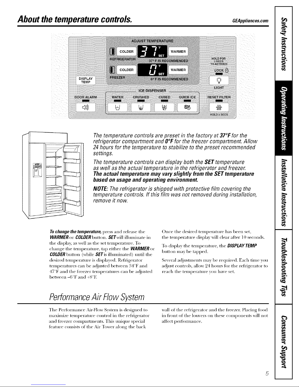
Aboutthe temperaturecontrols. GEAppliances.com
@
--/
The temperature controls are preset in the factory at 37°t: for the
refrigerator compartment and O°Ffor the freezer compartment. Allow
24 hours for the temperature to stabilize to the preset recommended
settings.
The temperature controls can display both the SET temperature
as well as the actual temperature in the refrigerator and freezer.
The actual temperature may vary slightly from the SET temperature
based on usage and operating environment.
NOTE:The refrigerator is shipped with protective film covering the
temperature controls. If this film was not removed during installation,
remove it now.
Tochange the temperature, press and release the
WARMER or COLDERbutton. SETwill ilhmfinate in
tile display, as well as the set wmi_erature. To
change the temperature, tap either the WARMER or
COLDERbutton (while SETis illmninated) tmfil the
desired telnl)erattu'e is displayed. Refl'igerator
temperatures can be ac!iusted between 34°F and
47°F and tile fl'eezer teini)eratures can be ac!iusted
between -6°F and +8°E
Once the desired temperatm'e has been set,
the temperatm'e display will clear after 10 seconds.
To display the temperatm'e, the DISPLAYTEMP
button may be tapped,
Several a(!jusunents may be required, Each time you
ac!iust (_)ntrols, allow 24 horns fin" the refl_igerator to
reach the temperatm'e you have set.
PerformanceAk FlowSystem
The Perfi)mlance _M_=Flow System is designed to
maximize teml)eratm'e control in the refligerator
and fl'eezer compartments. This tmique special
teanu'e consists of the :Mr Tower along the back
wall of the refligerator and the fl'eezei; Placing fi_od
in fl'ont of tile lou',e_ on these components will not
affect pe_tomlance,
Page 6

Aboutthe water filter.(onsomemodels)
Place the top of the cartridge up
inside the cartridge holder and
slowly turn it clockwise.
Water Filter Cartridge
The water filter cartridge is located in the
top grille c()ml)artnmnt. Flip up the panel
top grille to access the water filte_;
When to Replace the Filter
There is a replacement indicator light tot
the water filter cartridge on the dispense_;
This light will mrn orange to tell you that
you need to replace tile filter soon.
Tile filter cartridge should be replaced
when tile replacement indicator light turns
red or if the flow of water to the dispenser
or icemaker decreases.
Installing the Filter Cartridge
Tile filter cartridge is designed to filter
500 gallons ot water (lasting al)l)rOxilnately
12 months).
O If you, are rei)lacin(*_ tile cartridoe_, first
remoxe the old one b_ slowly tin'him*
it counterclockwise. Do not pull down
on the cartridge. A small amo/mt of
water may drip d(>wn.
0 Fill the replacement cartridge with
water from tile tap to alh)w for better
flow fl'om the dispenser immediately
after installation.
RESETWATERFILTER
HOL03SECS 0
Lining up tile arrow on tile cartridge
and tile cartridge holder, place tile
top ot tile new cartridge up inside
tile h(>lde_: Do not push it up into
the holder:
Slowly mrn it clockwise tmtil tile filter
cartridge stops. DO NOTOVERTIGHTEN.
_s you mrn tile cartridge, it will
automatically raise itself int(> position.
Cartridge will rotate about l/4 ttlril.
O Run water fl'om tile dispenser tot
3 mimKes (about 1½ gallons) to clear
tile s_stem and prevent sputtering.
0 Press and hold tile RESETWATERFILTER
button on tile dispenser for 3 seconds.
NOTE:A newly-installed water filter
cartridge may cause water to spurt fl'om
the dispense_:
Filter Bypass Plug
Y)u must use tile filter b)pass plug
when a replacement filter cartridge is not
available. The bypass i)lug will be taped to
the door bin in the new trait.
NOTE:The dispenser and tile icemaker
will not operate without the filter or filter
bypass ph N.
Replacement Filters:
Toorder additional filter cartridges
in the United States, visit our Webs#e,
GEAppliances.com, or call
GEParts and Accessories, 800.626.2002.
GWF
Suggested Retail ,$34.95 USD
(]ustomet_ in (hnada should consult
tile xellow pages tot tile nearest Camco
Serx ice Center:
Page 7
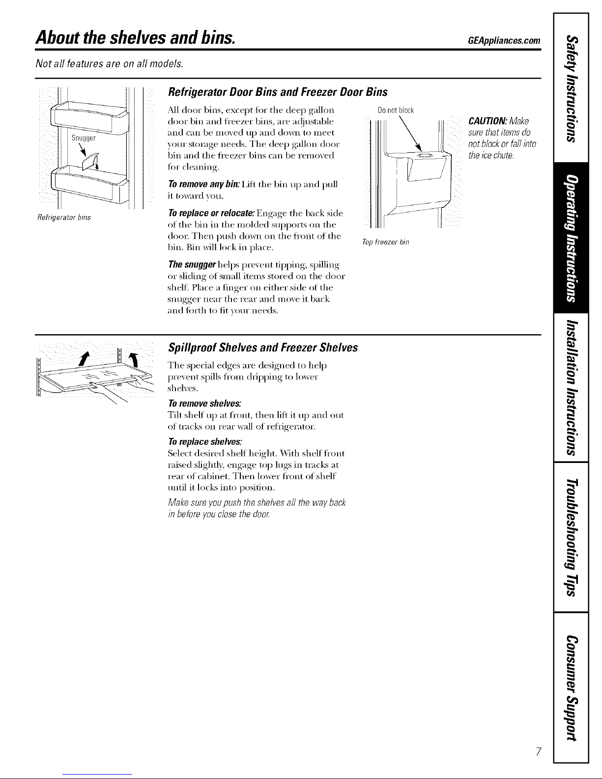
Abouttheshelvesandbins. GEAppliances.com
Not all features are on all models.
Refrigerator bins
Refrigerator Door Bins and Freezer Door Bins
?dl door bins, except for the deep gallon Donot block
door bin and fl'eezer bins, are ac!justnble
and can be moved tlI) and down to nleet
your storage needs. The deep gallon door
bin and the fl'eezer bins can be removed
for cleaning.
Toremove any bin:I,ifi the bin up and pull
it t()l_lrd VOtl.
Toreplace or relocate: Engage the back side
of the bin in the molded sui)ports on the
do(n: Then push down on the ti'ont of the
bin. Bin will lock in place.
The snugger helps prevent tii)ping, spilling
or sliding of small items stored on the door
shell Place a finger on either side of the
snugger near the rear and move it back
and torth to fit vom" needs.
Topfreezer bin
CAUTION:Make
surethatitemsdo
notblockorfail into
theicechute.
Spillproof Shelves and Freezer Shelves
The special edges are designed to help
prevent spills ti'om dripping to lower
shelves.
Toremove shelves:
Tilt shelf up at front, then lift it up and out
of tracks on rear wall of refrigerator.
Toreplace shelves:
Select desired shelf height. _\]th shelf fl'ont
raised slightly; engage top lugs in tracks at
rear of cabinet. Then lower ti'ont of shelf
tmtil it locks into position.
Make sure you push the shelves all the way back
in before you close the doo_
Page 8
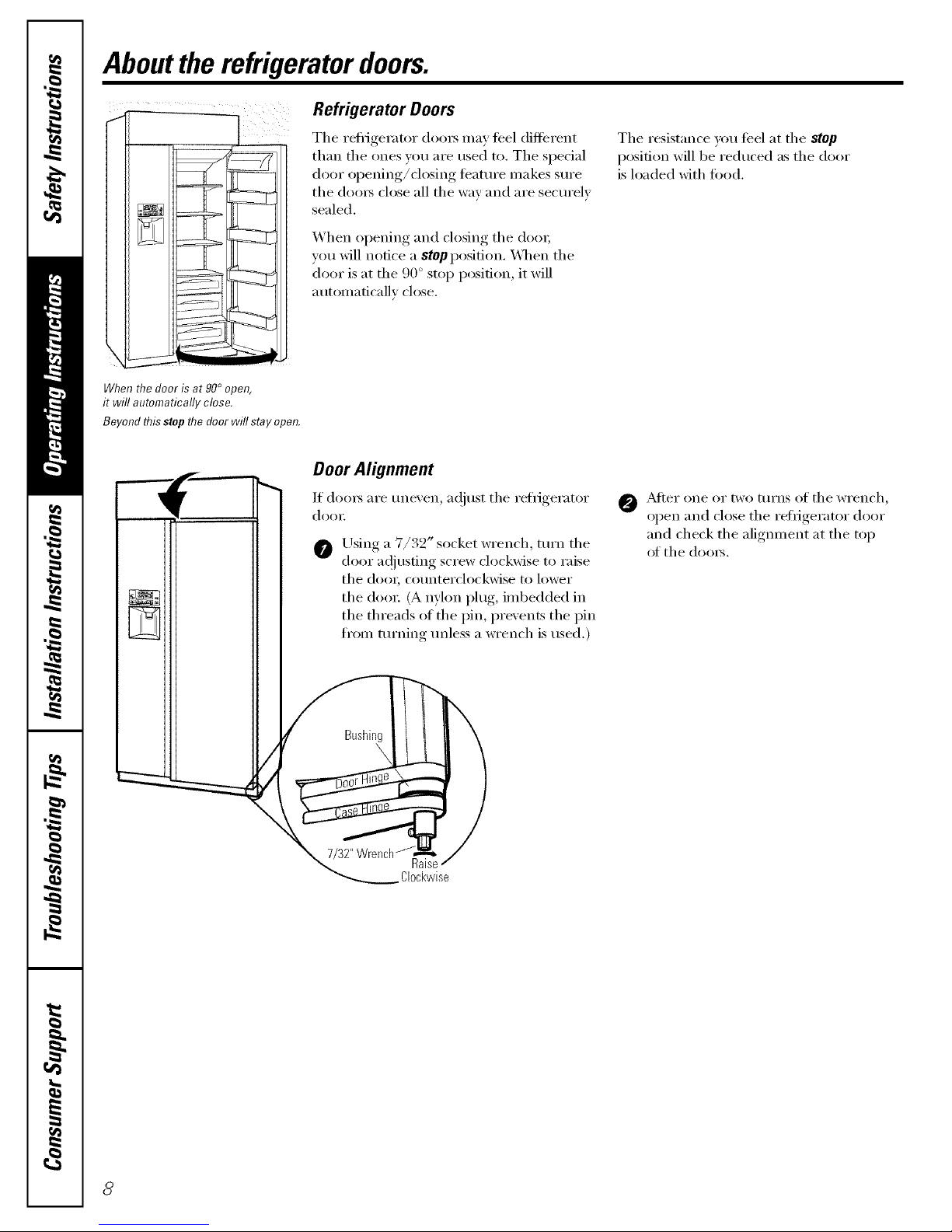
Abouttherefrigeratordoors.
Refrigerator Doors
Tile reti_igerator (loo_ may teel different
than the ones you are used to. The special
door oi)ening/closing feature Inakes sure
tile (loox_ close all tile way and are securely
sealed.
When opening and closing tile doo_;
you will notice a stopposition. _]/en tile
door is at the 90 ° stop position, it will
automaticallv close.
Tile resistance you ti_el at tile stop
position will be reduced as tile door
is loaded with fi)od.
When flTedoor is at 90° open,
it will automatically close.
Beyond flTisstop flTedoor will stay open.
Door Alignment
1t (loo_ are unexen, a(!iust tile retrigerator
doo_:
Using a 7/32" socket wrench, turn tile
door a(!jusdng screw clockwise to raise
the doo_; counterclockwise to lower
tile doo_: (A nyhm I)lug, imbedded in
the threads of the pin, prevents the pin
fi'om turning unless a wrench is used.)
/
O AJ[er ()lie or two ttlrns of tile wI'ench,
oI)en.....and close the refrigerator, door
and check the alignment at the top
of the (loo_s.
Page 9
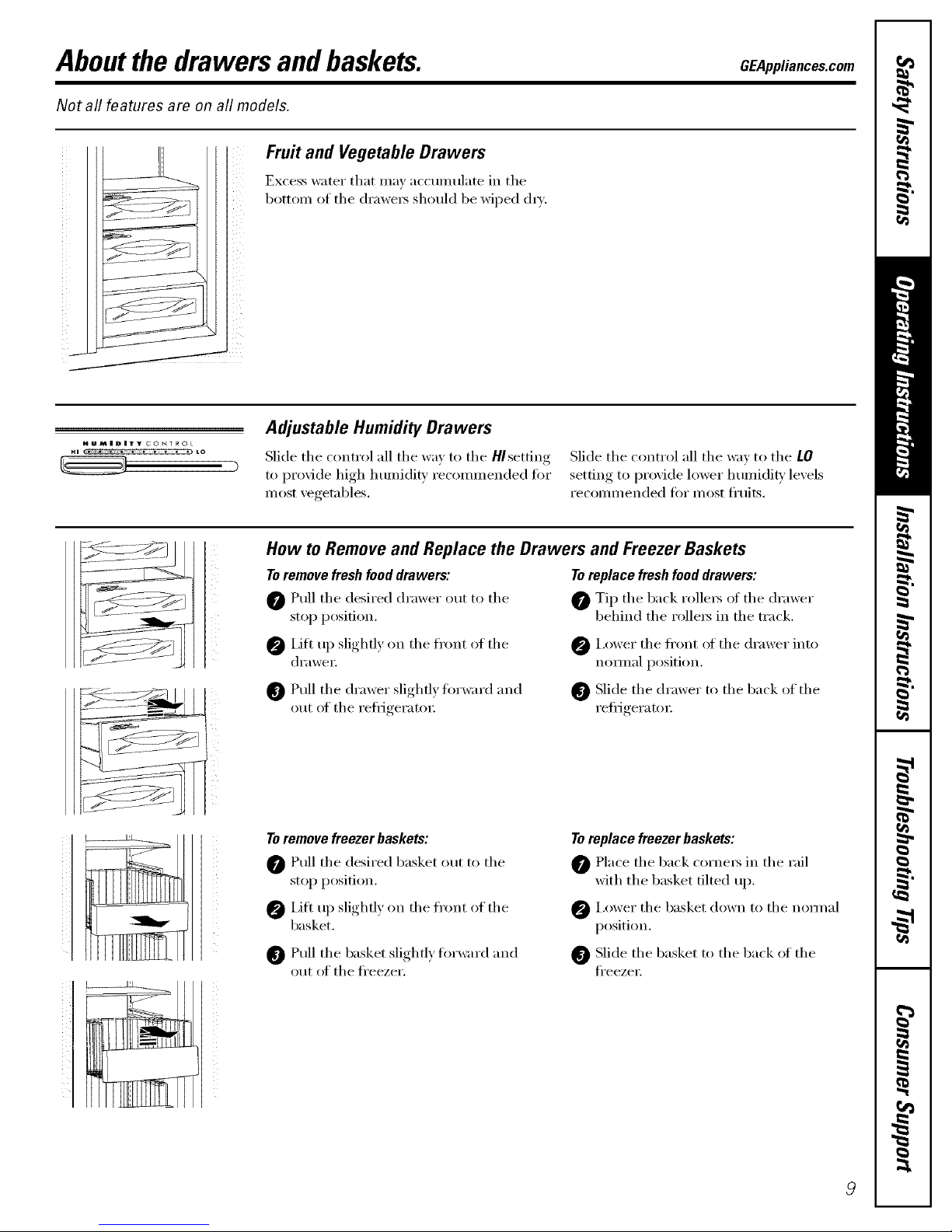
Aboutthe drawers andbaskets. GEAppliances.com
Not all features are on all models.
Fruit and Vegetable Drawers
Excess water that may ac('mnulate in the
bottom of the (h'awe_ should be wiped (h'_.
HUMIDITY CONTROL
HI • • • ,_ to
Adjustable Humidity Drawers
Slide the control all the way to the HIsetting
to provide high humidi_' recommended fin.
most vegetables.
Slide the control all the way to the lO
.settin,*_ to proxide lower h umidi_' lexels
recolnlnended fi)r most fl'uits.
(
_7
How to Remove and Replace the Drawers and Freezer Baskets
To remove fresh food drawers: To replace fresh food drawers:
0 Pull the desired drawer out to the 0 Tip the back rolle_ ot the drawer
stop position, behind the rollers in the track.
IJtt up slightly on the front of the
drawei:
@I,ower the fl'ont of the drawer into
nOlIll}ll position.
Pull the drawer slightly forward and
()tit of the refl_Jgeratoi:
Slide the drmver to the back of the
Fefl_geratoi:
To remove freezer baskets:
Pull the desired basket out to the
stop position.
@ i,ifl up slightly on the fl'ont of the
basket.
0 Pull the basket slightly forward and
out of the fl'eezer.
Toreplace freezer baskets:
Place the back corne_ in the rail
with the basket tilted up.
@ i,ower the basket down to the nom/al
position.
Slide the basket to the back of the
fl'eezei:
Page 10

Aboutthe ice and water dispenserandautomaticicemaker.
A newly installed refrigerator may take 12to 24 hours to begin making ice.
AcgessDo0r _
IceStorageBin j/t /f
Mechanism
Ice Storage Bin
To remove:
I,ift u I) the access door to reach the
icelnaker. Set the icelnaker power switch
to the 0 (off) position. _,_ ith the access
door closed, sui)port the storage bin at
the bottom while slightly lifting. Pull bin
straight out.
Toreplace:
Slide the bin back tmtil the tab on
the bin locks into the slot on the shelf.
If the bin does not go all the way back,
relnove it and rotate the dlive n_echai_ism
l/4 turn. Then push the bin back again.
Important facts about your
ice and water dispenser
Do not add ice fi'om trays or 1)ags to the
storage bin. It inay not crush or dispense
well.
Avoid ovedilling glass with ice and use of
narrow or extramdl glasses. Backed-up ice
canjaln the chute or cause the door in
the chute to fl'eeze shut. If ice is blocking
the chute, poke it through with a wooden
spoon.
Beverages and fi)ods should not be
quick-chilled in the ice storage bin.
Cans, bottles or food packages in the
storage bin inav cause the icelnaker
oi" auger to jam.
To kee I) dispensed ice fl'om nfissing
the glass, put the glass close to, but not
touching, the dispenser oi)ening.
Solne crushed ice inay be dispensed
even though you selected CUBED. This
hai)i)ens occasionally when a ti_w cubes
accidentally get directed to the crushei:
_M*eI"crushed ice is dispensed, some
water inay dri I) fl'Oln the chute.
The first glass of water dispensed may
be wanner than the tollowing ones.
This is nomml.
10
Automatic Icemaker
A newly-installedrefrigeratormaytake12-24 Power
hourstobeginmakingice. Switch
The icelnaker will produce seven cubes per
c)'cle---aI)I)roMmately 15 cycles or inore in
a 24-hour peliod, dei)ei_ding on fi'eezei"
COI]/l)_lI'[lIlent [eii/l)ei'il[lli'e _i'ooii/
teml)erature, imlnber (ff door oi)enings
and other use conditions.
If the retiigerator is operated befiwe the
water cotmectiot_ is inade to the icelnaket;
set the power switch to 0 (off}.
When the reli-igerator has been cotmected
to the water suppl); set the power switch to
I (on}. The green light will come on.
Throw away the fii_t flfll bucket of ice.
Be sure i_othing interteres with the sweep
of the feeler aim.
When the bin fills to the level ot the teeler
aim, the icelnaker will stop I)rodudng ice.
It is nolmal fi)I" several cubes to be joined
togethei;
Icemake[
Green
PowerLight FeelerArm
If ice is not used fl'equenfly, old ice cubes
will becolne cloudy, taste st;de and shrii_k.
_Mtei" the icelnaker has been turned on
again, there will be a delay of about 45
inilmtes bet0re the icelnaker resulnes
ol)erations.
NOtE:Inhomes with lowe>than-average
water pressure, you Inay hear the icenlaker
water \;dve cycle on several tilnes when
inakii_g one batch of ice. Recommended
water pressure is 60 psi.
Page 11
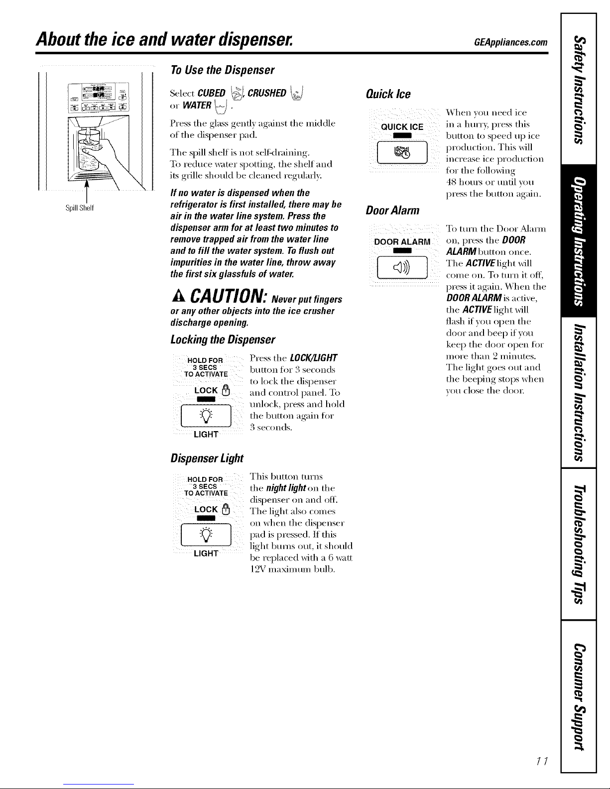
Aboutthe ice and water dispenser. GEAppliances.com
SpillShelf
ToUsetheDispenser
SelectCUBEDI_]; CRUSHEDi_]
or WATERt('j
x
Press the glass gently against the middle
of the dispenser pad.
The spill shelf is not selfkh'aining.
To reduce water spotting, the shelf and
its grille shoukl be cleaned regularl}:
If no water isdispensedwhen the
refrigerator is first installed, there may be
air in the water line system. Press the
dispenser arm for at least two minutes to
remove trapped air from the water line
and to fill the water system.To flush out
impuritiesin the water line, throw away
the first six glassfulsof water.
_k CAUTION: Never putflngers
or anyother objects intotheice crusher
dischargeopening.
Lockingthe Dispenser
HOLD FOR Press the LOCK/LIGHT
3 SECS b/ltton ]'or .'4 seconds
TOACTIVATE
to lock the dispenser
LOCK _ and control panel. To
unlock, press and hold
"0:" the button again fl)r
LIGHT 3 seconds,
Quick Ice
When you need ice
QUICK ICE in a hmTy, press this
m button to speed up ice
[ ) produc0OlL This will
_{_ increase ice produc0on
fl)r tile fi)llowing
48 hom_ or tin01 wm
press the button again.
OoorAlarm
DOOR ALARM
ram=
<,))
To tm'n the Door _Mam_
on, press the DOOR
ALARMbumm once,
The ACTIVElightwill
(oi/le on. To ttlI'n it off,
press it again. _'hen the
DOOR ALARM is a cove,
the AC771/Elight will
flash if you open the
door and beep if you
kee I) the door open fi)r
more than 2 minutes.
The light goes out and
the beeping stops when
vo//close the dooi;
Dispenser Light
HOLDFOR
3 SECS
TOACTIVATE
Lock
This button tm'ns
the night light on the
dispenser on and off.
The light also comes
on when the dispenser
"_:" pad is pressed. If this
I
light b/llIlS ()tit, it should
LIGHT be replaced with a 6 watt
12Vmaximum bulb.
11
Page 12

Careand cleaningofthe refrigerator.
Dispenserdriparea.
Cleaning the Outside
Thespill shelf and the area beneath it shc,tdd
be cleaned periodicall_ with a mild liquid dish
detergent.
Dispenser pad. Before cleaning, lock
the dispenser by pressing the LOCK/LIGHT
button tot 3 seconds to prevent activating
the dispense_; Clean with warn/water
and a mild liquid dish detergent, Rinse
thoroughly and wipe dry, Unlock the
dispenser by pressing the LOCK/LIGHT
button fin" 3 seconds.
Doorhandles. Clean with a cloth dampened
with soapy water: Dry with a soft cloth.
Keep the outside clean. Wipe with a clean
cloth lightly dampened with mild liquid
dish detergent. Dry with a clean, soft cloth.
Do not Mpe the refl_igerator with a soiled
dish cloth or wet towel. These may leave a
residue that can damage the finish. Do not
use scotwing pads, powdered cleaners,
bleach or cleaners containing bleach
because these products can scratch and
damage the finish.
Stainless steel. Regularly clean and
polish the Stainless Steel L)_:,_:,_with a
commercially available stainless steel
cleaner such as Stainless Steel MagiU"
to preserve and protect the fine finish.
Stainless Steel Magic is a\:filable through
GE Parts and Accessories, 800.626.2002,
or GEAppliances.com. Order part ntllllbeI"
_TX10X15.
Do not use appliance wax or polish
on the stainless steel,
Cleaning the Inside
Turnoffpower at the circuit breaker or fuse
box before cleaning. If this is not pra(tical,
wIJng excess illoisttlre o/It oil sponge or
cloth when cleaning around switches, lights
or controls.
Use warn/ water and baking soda solution--
about a tablespoon (15 ml) of baking soda
to a quart (1 liter) of watex: This both
cleans and neutralizes odoxs. Thoroughly
rinse and wipe dry.
Other parts of the refrigerator, including door
gaskets, snack pan and vegetable (h'awe_,
ice storage bin and all plastic parts, can be
cleaned the same way.
Do not wash the tray or any plastic
reli_igerator parts in the dishwasher:
Avoid cleaning cold glass shelves with hot
water because the extreme temperature
difference may cause them tobreak. Handle
glass shelves carefully. Bumping tempered
glass can cause itto shatter.
/2
Page 13
GEAppliances.com
Preparing for Vacation
FOI" long \_('atlOiiS oi" absences, Feillove
food and unplug the refl_igerator. Clean the
interior with a baking soda solution of one
tablespoon (15 ml) of baking soda to one
quart (1 liter) ot water: I,eave the doo_
open.
Set the icemaker power switch to the 0 (off)
position and shut off the water supply to
the refl_igeratm:
If the temperatm'e can drop below fl'eezing,
have a qualified se_Mcer drain the water
supply system to prevelK serious properQ,
damage due to flooding.
Preparing to Move
Secure all loose items such as shelves and
(h'awe_ by taping them secm'ely in place
to prevent damage.
CAUTION:Duetetheweight
and size of this refrigerator, and to reduce the
risk ofpersonal injury or damage to the
product, A MINIMUM OF4 PEOPLEARE
REQUIREDTO BRING THEUNIT INTO THE
HOME AND 2 PEOPLEAREREQUIREDFOR
PROPERINSTALLATION.
Besurethe refrigeratorstaysin anupright
positionduringmoving
13
Page 14
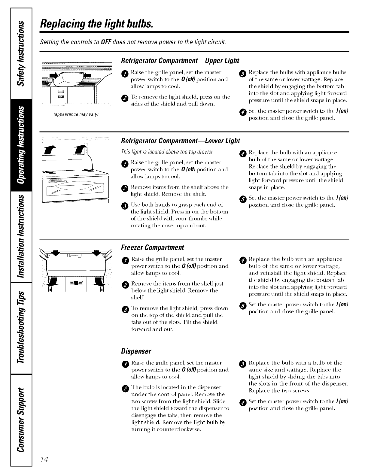
Replacingthe lightbulbs.
Setting the controls to OFFdoes not remove power to the light circuit.
.......................................................................................Refrigerator Compartment--Upper Light
(appearance may vary)
@ Raise tile gl_ille panel, set tile master
power switch to tile 0 (off)position and
allow lamps to cool.
@ To x'emove the light shield, press on the
sides of tile shield and pull down.
@ Replace tile bulbs with appliance bulbs
of the same or lower wattage. Replace
the shield by engaging the bottom tab
into tile slot and aI)plying light torward
pressure/mtil tile shield snaps in place.
@ Set tile master power switch h) tile I (On)
position and close tile grille panel.
Refrigerator Compartment--Lower Light
Thishght is located above the top drawe_
@ Raise tile gl_ille panel, set tile master
power switch to tile 0 (Off)position and
allow lamps to cool.
Remove items flxm_ tile shelf above tile
light shield. Remove the shel£
Use both hands to grasp each end of
the light shield. Press in on the bottom
of the shield with your thumbs while
rotating tile cover up and out.
Replace tile bull) with an appliance
bulb of tile same or lower wattage.
Replace tile shield by engaging tile
bottoln tab into tile slot and appl)ing
light forward pressm'e tmtil tile shield
snaps in place.
O Set tile inaster power switch to tile I(Oil)
position and close tile grille panel.
Freezer Compartment
@ Raise tile grille panel, set tile master
power switch to tile 0 (Of) position and
allow lamps to cool.
@ Reinoxe tile items ti'()m tile shelf just
below the light shield. Remoxe the
shel£
@
To remoxe tile light shield, press down
on the top of the shield and pull the
tabs out of the slots. Tilt the shield
fi)rward and out.
Replace tile bull) with an appliance
bulb of the same or lower wattage,
and reinstall the light shield. Replace
the shield by engaging the bottom tab
into tile slot and apI)lying light forward
pressm'e tmtil tile shield snaps in place.
O Set tile master power switch to tile I(on]
position and close tile grille panel.
Dispenser
@ Raise tile grille panel, set tile master
power switch to the 0 (off} position and
allow lamps to cool.
@ Tile bulb is located in tile dispenser
trader the control panel. Remove the
two screws fl'om the light shield. Slide
the light shield toward the dispenser to
disengage the tabs, then remove the
light shield. Remove the light bulb b v
turning it co/mterclockwise.
Replace tile bulb with a bulb of tile
same size and wattage. Replace the
light shield by sliding the tabs into
the slots in the fl'ont of the dispenser.
Replace the two screws.
@ Set tile master power switch to tile I (0/1)
position and dose tile grille panel.
14
Page 15
Installation
Instructions
Built-InSide-By-Side
Refrigerators
PSB42LGRWV,PSB42LGRBV,PSB42LSRBV,
PSB48LGRWV,PSB48LGRBV,PSB48LSRBV
l If you have questions, call 800.GE.CARES (800.432.2737) or visit our website at: www.GEAppliances.com I
BEFORE YOU BEGIN
Read these instructions completely
and carefully.
• IMPORTANT - Observeall
governing codes and ordinances.
• Note to Installer - Be sure to leave these
instructions for the consumer's and local
inspector's use.
• Note to Consumer - Keep these instructions
with your Owner's Manual for future reference.
• Skill Level - Installation of this refrigerator
requires basic mechanical, carpentry and
plumbing skills. Proper installation is the
responsibility of the installer. Product failure
due to improper installation is not covered
under the GE Appliance Warranty. See
warranty information.
• Completion Time - 90 minutes (new
installations require more time than
replacement installations).
,_ CAUTION:
Due to the weight and size of this refrigerator,
and to reduce the risk of personal injury or
damage to the product, A MINIMUM OF 4
PEOPLE ARE REQUIRED TO BRING THE UNIT
INTO THE HOME AND 2 PEOPLE ARE
REQUIRED FOR PROPER INSTALLATION.
,A WARNING:
• These refrigerators are top-heavy and must
be secured to prevent the possibility of
tipping forward. Anti-Tip protection is
required. See Step 4 on page 30 for details.
• Use this appliance only for its intended purpose.
• Immediately repair or replace electric power
supply cords that become frayed or damaged.
• Set the Master Power switch to the
O (OFF) position before cleaning or making
repairs.
• Repairs should be made by a qualified
service technician.
For Profile TM local service in your area,
call 1.800.432.2737.
For Profile TM service in Canada,
call 1.888.880.3030.
For Profile TM Parts and Accessories,
call 1.800.626.2002.
www.GEAppliances.com
READ CAREFULLY.
KEEP THESE INSTRUCTIONS.
15
Page 16
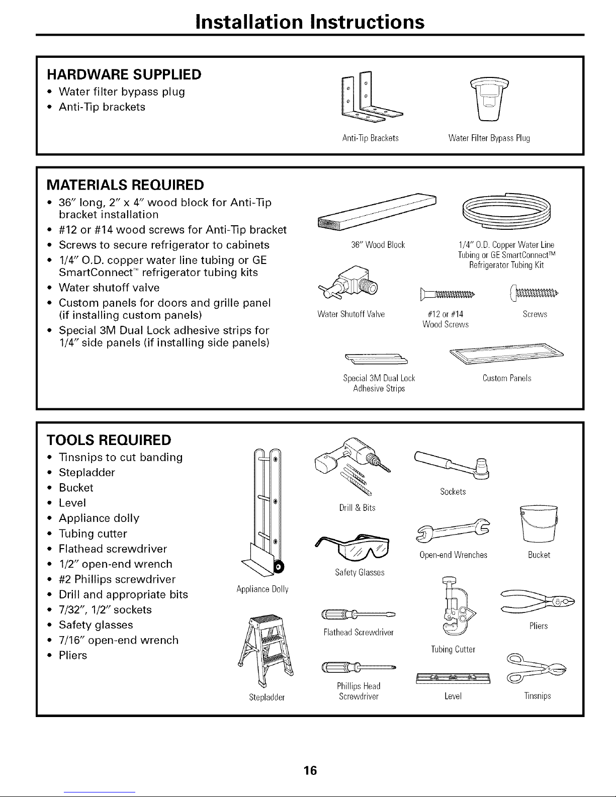
Installation Instructions
HARDWARE SUPPLIED
• Water filter bypass plug
• Anti-Tip brackets
Anti-TipBrackets Water Filter Bypass Plug
MATERIALS REQUIRED
• 36" long, 2" x 4" wood block for Anti-Tip
bracket installation
• #12 or #14 wood screws for Anti-Tip bracket
• Screws to secure refrigerator to cabinets
• 1/4" O.D. copper water line tubing or GE
SmartConnect T'_refrigerator tubing kits
• Water shutoff valve
• Custom panels for doors and grille panel
(if installing custom panels)
• Special 3M Dual Lock adhesive strips for
1/4" side panels (if installing side panels)
36"WoodBlock
Water Shutoff Valve
#12or#14
WoodScrews
1/4" O.D.CopperWater Line
TubingorGESmartConnectTM
RefrigeratorTubingKit
Screws
Special3MDualLock
AdhesiveStrips
Custom Panels
TOOLS REQUIRED
• Tinsnipsto cut banding
• Stepladder
• Bucket
• Level
• Appliance dolly
• Tubing cutter
• Flathead screwdriver
• 1/2" open-end wrench
• #2 Phillips screwdriver
• Drill and appropriate bits
• 7/32", 1/2" sockets
• Safety glasses
• 7/16" open-end wrench
• Pliers
ApplianceDolly
Stepladder
Drill& Bits
Safety Glasses
FlatheadScrewdriver
PhillipsHead
Screwdriver
Sockets
Open-endWrenches
TubingButter
Level
Bucket
Pliers
Tinsnips
16
Page 17

Installation Instructions
THE INSTALLATION SPACE
I_*Finished Width
3"
74"
FromFloor
to Bottom
of Electrical
*The finished cutout width must be:
41-1/2" for 42" models and 47-1/2"
for 48" models
Water and Electrical Locations
The opening must be prepared with the
electrical and water supply located as shown.
The cutout depth must be 24"
The refrigerator will project forward, slightly
beyond adjacent cabinets, depending on
your installation.
Additional Specifications
• A 120 volt, 60Hz, 15 or 20 amp power
supply is required. An individual properly
grounded branch circuit or circuit breaker
is recommended. Install a properly
grounded 3-prong electrical receptacle
recessed into the back wall. Electrical must
be located on rear wall as shown.
Note: GFI (ground fault interrupter) is not
recommended.
• Water line can enter the opening through
the floor or rear wall. The water line
installed should be 1/4" O.D. copper tubing
or GE SmartConnect T"tubing between the
cold water line and water connection
location. The line should be long enough
to extend to the front of the refrigerator.
Installation of an easily accessible shutoff
valve in the water line is required.
DIMENSIONS AND CLEARANCES
25-3/8" CaseDepth
_Shipping height
_Case Width_ _ _ The front height
_-[_ T may be adjusted
|1--_ II _ | from 83-1/2"to 84-1/2"
/I _ _'- / by adjusting front and
/I II III / rear leveling legs a
II II Ill I maximum of 1".
'81-3/4"1 ]1-_ % _84"From
at mearl I] _ I Ill Floorto
T° Fr m
DepthIncluding
Handles26-7/8"
**The case width must be: 41" for
42" models and 47" for 48" models
Product Clearances
These refrigerators are equipped with a 2
position door stop. The factory set 130 ° door
swing can be adjusted to 90 ° if clearance to
adjacent cabinets or walls is restricted.
130 ° Door Swing 90 ° Door Swing
I*D*l
F_ame
I-D4
Models A B C D
42" 12-3/16" 16" 24" 4"
48" 13-7/16" 18-9/16" 28" 4"
Allow minimum clearances for Freezer
door (Dimension A) and Fresh Food door
(Dimension B) for a full 130 ° door swing
and to allow for drawer removal.
Four inch (4") minimum clearance is required
when door swing is adjusted to 90 °. If the 90 °
door stop position is used, drawer access is
maintained, but drawer removal is restricted.
See illustrations, pages 18 and 19, to
determine door swing interaction with
adjacent cabinets or countertops.
17
Page 18

Installation Instructions
Refrigerator
23-7/8"From
Rearof
Refrigerator
3/4"
3/4" CustomPanel
(NominalSize)
FreshFood
Door
BackerPanel
\
\
\
Top View
130 ° Door Swing
(factory setting)
Scale 1:1
18
Page 19
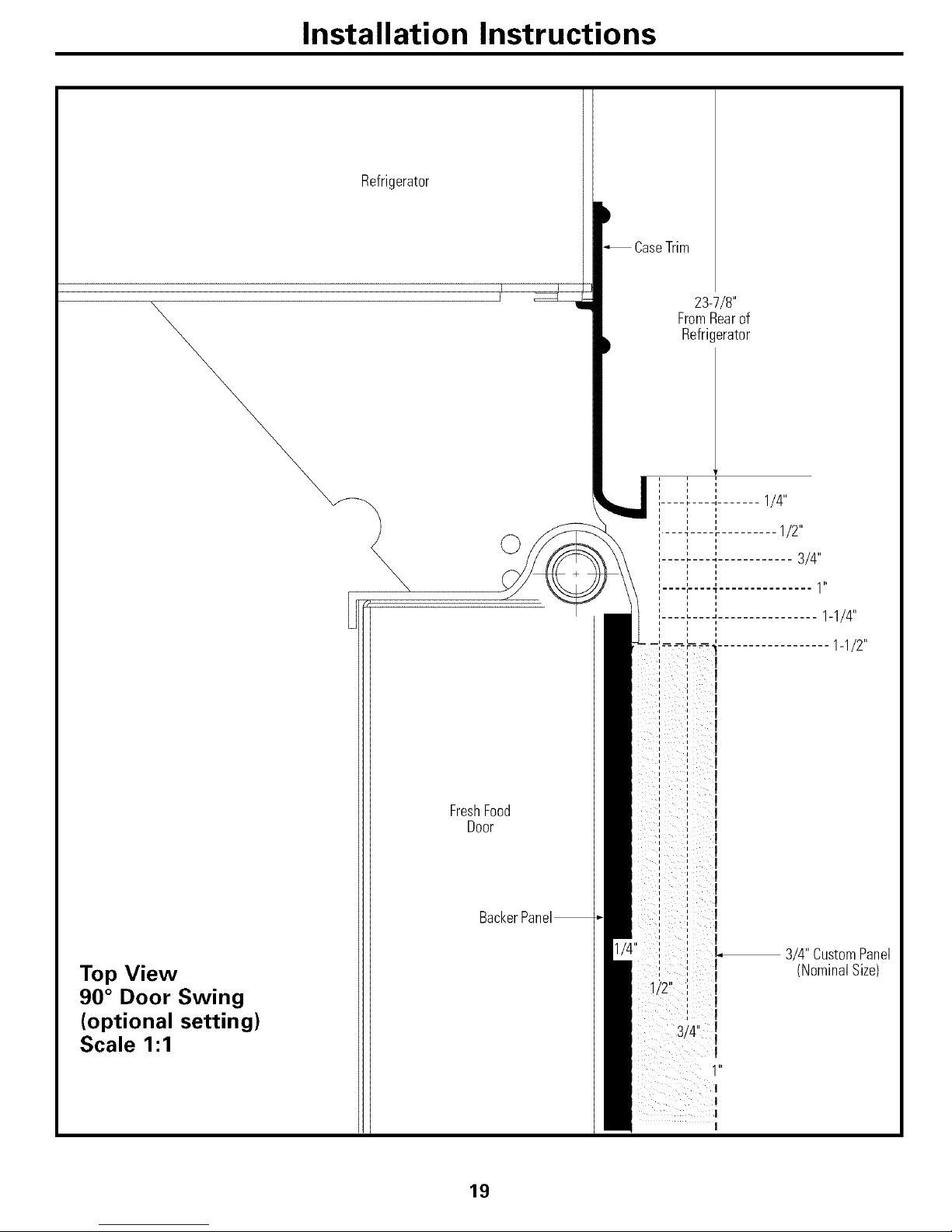
Installation Instructions
Refrigerator
©
Top View
90 ° Door Swing
(optional setting)
Scale 1:1
FreshFood
Door
CaseTrim
23-7/8"
FromRearof
Refrigerator
......... :....... 1/4"
,,
..... 1/2"
......... 3/4"
.... ,.... ff............... I l'
1-1/4"
1-1/2"
3/4" CustomPanel
(NominalSize)
19
Page 20
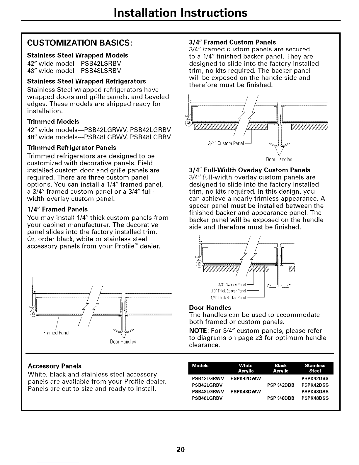
Installation Instructions
CUSTOMIZATION BASICS:
Stainless Steel Wrapped Models
42" wide modeliPSB42LSRBV
48" wide modeliPSB48LSRBV
Stainless Steel Wrapped Refrigerators
Stainless Steel wrapped refrigerators have
wrapped doors and grille panels, and beveled
edges. These models are shipped ready for
installation.
Trimmed Models
42" wide modelsipSB42LGRWV, PSB42LGRBV
48" wide modelsipSB48LGRWV, PSB48LGRBV
Trimmed Refrigerator Panels
Trimmed refrigerators are designed to be
customized with decorative panels. Field
installed custom door and grille panels are
required. There are three custom panel
options. You can install a 1/4" framed panel,
a 3/4" framed custom panel or a 3/4" full-
width overlay custom panel.
114" Framed Panels
You may install 1/4" thick custom panels from
your cabinet manufacturer. The decorative
panel slides into the factory installed trim.
Or, order black, white or stainless steel
accessory panels from your Profile *'_dealer.
3/4" Framed Custom Panels
3/4" framed custom panels are secured
to a 1/4" finished backer panel. They are
designed to slide into the factory installed
trim, no kits required. The backer panel
will be exposed on the handle side and
therefore must be finished.
][
DoorHandles
3/4" Full-Width Overlay Custom Panels
3/4" full-width overlay custom panels are
designed to slide into the factory installed
trim, no kits required. In this design, you
can achieve a nearly trimless appearance, A
spacer panel must be installed between the
finished backer and appearance panel. The
backer panel will be exposed on the handle
side and therefore must be finished.
[]
Framed Panel
DoorHandles
1/4"ThickBackerPanel
Door Handles
The handles can be used to accommodate
both framed or custom panels.
NOTE: For 3/4" custom panels, please refer
to diagrams on page 23 for optimum handle
clearance.
Accessory Panels
White, black and stainless steel accessory
panels are available from your Profile dealer.
Panels are cut to size and ready to install.
PSB42LGRWV PSPK42DWW PSPK42DSS
PSB42LGRBV PSPK42DBB PSPK42DSS
PSB48LGRWV PSPK48DWW PSPK48DSS
PSB48LGRBV PSPK48DBB PSPK48DSS
2O
Page 21

Installation Instructions
1/4" FRAMED PANEL DIMENSIONS
If you choose to install framed panels, they
must be cut to the dimensions shown. The
panels will slide into the frame on the door
and grille.
Door
\
\
\
/ Reveal
IMPORTANT NOTE: Maximum weight
for Fresh Food panel is 70 pounds and
30 pounds total for Freezer panels.
A
[ GrillePanel ]_
F
Dispenser _
Cutout
C
Freezer Fresh Food
Panel Panel Front Panel Dimensions (in inches)
42" Models 39-15/16 10-3/4 67-7/8
48" Models 45-31/32 10-3/4 67-7/8
r.'l I:1 [7 Ira] I:I [tl
16-7/16 22-11/32 17-13/16 35-5/32
18-15/32 26-15/32 17-13/16 35-5/32
IMPORTANT NOTE: Dispenser Trim
The refrigerator is supplied with factory installed
dispenser trim.
• If panel is less than 1/4" thick, a noticeable gap will be
created around the dispenser trim. Foam tape may be
applied on the door to improve the fit.
• If panel is more than 1/4" thick, the panel will not fit
behind the trim,
21
Page 22

Installation Instructions
3/4" FRAMED CUSTOM PANEL OPTION
For a more custom appearance, 3/4" framed custom
panels may be installed on trimmed models. The overlay
panel is secured to a 1/4" finished backer panel. The
assembled custom panel then slides into the trim with
the same procedure described on page 33.
Door
1/4"
Backer f
Panel
.250 + .750 = 1.000 Maximum Total Panel Thickness
Overla
BackerPanel
NOTE: Left-to-right offset is not equal
to top-to-bottom offset.
3/4" FULL-WIDTH OVERLAY
CUSTOM PANEL OPTION
This design provides a nearly trimless appearance. The full
width overlay panel covers most of the door trim. In this design,
a spacer panel must be installed between the finished backer
and overlay panel,
OverlayPanel
Cust
I
, Overlay
',Door Panel_
'[ii4"er _, L.IO!ch
Panel Spacer
i
NOTE: Left-to-right offset is not equal
to top-to-bottom offset.
.250 + .10 + .750 = 1.100 Maximum Total Panel Thickness
IMPORTANT NOTE: Maximum total weight for any
assembled Fresh Food panel is 70 pounds and
30 pounds total for Freezer panels.
22
Page 23
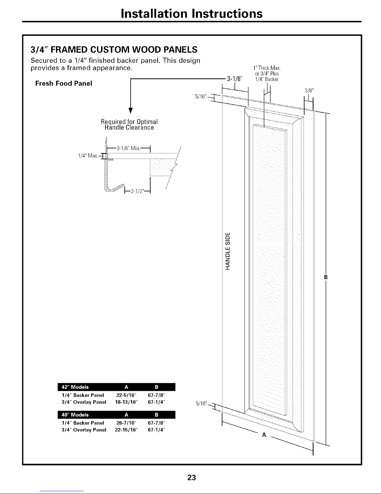
Installation Instructions
3/4" FRAMED CUSTOM WOOD PANELS
Secured to a 1/4" finished backer panel. This design
provides a framed appearance.
Fresh Food Panel
Required for Optimal
Handle Clearance
1/4" Max.--]"
--3-1/8" Min.'_
/
_'-- 2-1/2"J
Ir.,_ I:]
1/4" Backer Panel 22-5/16" 67-7/8"
3/4" Overlay Panel 18-13/16" 67-1/4"
Ir.,_ I:]
1/4" Backer Panel 26-7/16" 67-7/8"
3/4" Overlay Panel 22-15/16" 67-1/4"
3-1/8"
1"ThickMax.
or3/4" Plus
1/4" Backer
3/8"
A
23
Page 24

Installation Instructions
3/4" FRAMED CUSTOM WOOD PANELS
Secured to a 1/4" finished backer panel. This design provides a framed appearance.
1"ThickMax.
Grille Panel
F:I I:]
1/4" Backer Panel 39-15/16" 10-3/4" 5/16"_
3/4" Overlay Panel 39-7/16" 10-1/8"
F:I I:]
1/4" Backer Panel 45-15/16" 10-3/4"
3/4" Overlay Panel 45-7/16" 10-1/8"
Upper Freezer Panel
5/16"----_
1" ThickMax.
I
or 3/4" Plus I
1/4" Backer 3-1/8"
3/8"
Required for Optimal
Handle Clearance
I-'1 I:]
1/4" Backer Panel 16-7/16" 17-13/16"
3/4" Overlay Panel 12-15/16" 17-3/16"
I-'1 I:]
1/4" Backer Panel 18-7/16" 17-13/16"
3/4" Overlay Panel 14-15/16" 17-3/16"
1_3-1/8" IV]in_-
\k2-1z2q%
_--1/4"
Max.
Lower Freezer Panel
I-'1 I:]
1/4" Backer Panel 16-7/16" 35-1/8"
3/4" Overlay Panel 12-15/16" 34-1/2"
I-'1 I:]
1/4" Backer Panel 18-7/16" 35-1/8"
3/4" Overlay Panel 14-15/16" 34-1/2"
3/8"
3-1/8"
24
Page 25

Installation Instructions
3/4" FULL-WIDTH OVERLAY CUSTOM PANELS
This panel design provides a nearly trimless appearance.
Fresh Food Panel
Assemble the spacer
panel onto the finished
backer panel, Allow
1/2" clearance on the
top, bottom and hinge
side. Allow 3-5/8" on
the handle side. Secure
the panels with glue.
Be sure to observe
clearances shown on
all sides.
Secure the overlay
panel to the assembled
backer/spacer panel,
Use glue and screws,
Countersink screws
into the backer panel.
Finished
Backer
Panel
3-5/8"
Spacer
Required for Optimal
Nandle Clearance
3-1/8"
L--_1/2,,
_vM?_CT_L_I Ir.,_ I:]
1/4" Backer Panel 22-5/16" 67-7/8"
0.10" Spacer Panel 18-3/16" 66-7/8"
3/4" Overlay Panel 19-5/16" 68-1/8"
Ir.,_ I:]
1/4" Backer Panel 26-7/16" 67-7/8"
0.10" Spacer Panel 22-5/16" 66-7/8"
3/4" Overlay Panel 23-7/16" 68-1/8"
25
Page 26
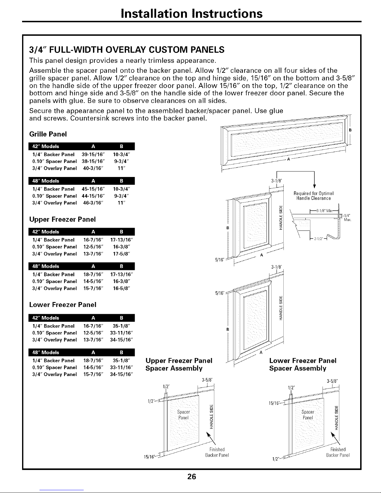
Installation Instructions
3/4" FULL-WIDTH OVERLAY CUSTOM PANELS
This panel design provides a nearly trimless appearance.
Assemble the spacer panel onto the backer panel. Allow 1/2" clearance on all four sides of the
grille spacer panel. Allow 1/2" clearance on the top and hinge side, 15/16" on the bottom and 3-5/8"
on the handle side of the upper freezer door panel. Allow 15/16" on the top, 1/2" clearance on the
bottom and hinge side and 3-5/8" on the handle side of the lower freezer door panel. Secure the
panels with glue. Be sure to observe clearances on all sides.
Secure the appearance panel to the assembled backer/spacer panel. Use glue
and screws. Countersink screws into the backer panel.
Grille Panel
F:I I:]
1/4" Backer Panel 39-15/16" 10-3/4"
0.10" Spacer Panel 38-15/16" 9-3/4"
3/4" Overlay Panel 40-3/16" 11"
3q/8"F:I I:]
1/4" Backer Panel 45-15/16" 10-3/4"
0.10" Spacer Panel 44-15/16" 9-3/4" Requiredfor Optimal
HandleClearance
3/4" Overlay Panel 46-3/16" 11"
Upper Freezer Panel
F:I I:]
1/4" Backer Panel 16-7/16" 17-13/16"
0.10" Spacer Panel 12-5/16" 16-3/8"
3/4" Overlay Panel 13-7/16" 17-5/8"
F:I I:]
1/4" Backer Panel 18-7/16" 17-13/16"
0.10" Spacer Panel 14-5/16" 16-3/8"
3/4" Overlay Panel 15-7/16" 16-5/8"
Lower Freezer Panel
5/16":
3q/8"
F:I I:]
1/4" Backer Panel 16-7/16" 35-1/8"
0.10" Spacer Panel 12-5/16" 33-11/16"
3/4" Overlay Panel 13-7/16" 34-15/16"
F:I I:]
1/4" Backer Panel 18-7/16" 35-1/8"
0.10" Spacer Panel 14-5/16" 33-11/16"
3/4" Overlay Panel 15-7/16" 34-15/16"
Upper Freezer Panel
Spacer Assembly
3-5/8"
15/161'_
Spacer
Panel
Z
I
Finished
BackerPallel
Lower Freezer Panel
Spacer Assembly
3-5/8"
15/16,,_1/2_
Spacer
Panel
1/2"_
Finished
BackerPallel
26
Page 27

Installation Instructions
SIDE PANELS
Side panels (not
supplied) must be
used whenever
the sides of the
refrigerator will be
exposed. The 1/4"
side panels will slip
into the side case
trim. Order side
panels from your
cabinet manufacturer.
*Depending on
installation height.
FLOORING
For proper installation, this refrigerator must
be placed on a level surface of hard material
that is at the same height as the rest of the
flooring. This surface should be strong
enough to support a fully loaded refrigerator,
or approximately 1500 lb.
NOTE: Protect the finish of the flooring. Cut a
large section of the cardboard carton and place
under the refrigerator where you are working.
GROUNDING THE REFRIGERATOR
IMPORTANT--Please read carefully
FOR PERSONAL SAFETY, THIS APPLIANCE
MUST BE PROPERLY GROUNDED.
The power supply cord of this appliance is
equipped with a three-prong (grounding)
plug which mates with a standard three-
prong (grounding) wall receptacle to
minimize the possibility of electric shock
hazard from this appliance.
Have the wall outlet and circuit checked by a
qualified electrician to make sure the outlet is
properly grounded.
OR REMOVE THE THIRD
(GROUND) PRONG
FROM THE POWER CORD.
Where a standard 2-prong wall outlet
is encountered, it is your personal
responsibility and obligation to have it
replaced with a properly grounded 3-prong
wall outlet.
DO NOT, UNDER ANY _
CIRCUMSTANCES, CUT
S
DO NOT USE AN ADAPTER PLUG TO
CONNECT THE REFRIGERATOR TO A
2-PRONG OUTLET.
DO NOT USE AN EXTENSION CORD
WITH THIS APPLIANCE.
27
Page 28
Installation Instructions
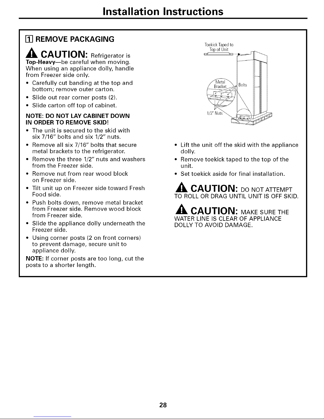
[] REMOVE PACKAGING
CAUTION: Refrigerator is
Top-Heavy--be careful when moving.
When using an appliance dolly, handle
from Freezer side only.
• Carefully cut banding at the top and
bottom; remove outer carton.
• Slide out rear corner posts (2).
• Slide carton off top of cabinet.
NOTE: DO NOT LAY CABINET DOWN
IN ORDER TO REMOVE SKID!
• The unit is secured to the skid with
six 7/16" bolts and six 1/2" nuts.
• Remove all six 7/16" bolts that secure
metal brackets to the refrigerator.
• Remove the three 1/2" nuts and washers
from the Freezer side,
• Remove nut from rear wood block
on Freezer side.
• Tilt unit up on Freezer side toward Fresh
Food side.
• Push bolts down, remove metal bracket
from Freezer side. Remove wood block
from Freezer side.
• Slide the appliance dolly underneath the
Freezer side.
• Using corner posts (2 on front corners)
to prevent damage, secure unit to
appliance dolly.
NOTE: If corner posts are too long, cut the
posts to a shorter length.
T0ekickTapedto
Topof Unit
[o "3_
1/2"Nut
• Lift the unit off the skid with the appliance
dolly.
• Remove toekick taped to the top of the
unit.
• Set toekick aside for final installation.
CAUTION: DO NOT ATTEMPT
TO ROLL OR DRAG UNTIL UNIT IS OFF SKID.
CAUTION: MAKE SURE THE
WATER LINE IS CLEAR OF APPLIANCE
DOLLY TO AVOID DAMAGE.
28
Page 29

Installation Instructions
[] INSTALL WATER LINE
• A cold water supply is required for
automatic icemaker operation, The water
pressure must be between 40 and 120 psi.
• Route 1/4" O.D. copper tubing or GE
SmartConnect TM tubing between cold water
line and the water connection location.
• Tubing should be long enough to extend
to the front of the refrigerator. Allow
enough tubing to accommodate bend
leading into the water line connection,
NOTE: The only GE approved plastic tubing
is supplied in the GE SmartConnect T'_
Refrigerator Tubing kits. Do not use any
other plastic water supply line; the line is
under pressure at all times. Certain types
of plastic may crack or rupture with age
and cause water damage to your home,
GE SmartConnect TM refrigerator tubing kits
are available in the following lengths:
2' (0,6m) WX08X10002
6' (1,8m) WX08X10006
15' (4.6m) WX08X10015
25' (7,6m) WX08X10025
Shut off the main water supply.
Turn on the nearest faucet long enough
to purge all the water from the line.
• Install a shutoff valve between the
icemaker water valve and cold water pipe
in a basement or cabinet. The shutoff
valve should be located where it will be
easily accessible.
NOTE: It is best to install the valve into a
vertical water pipe. If you install the valve into
a horizontal water pipe, make the connection
at the top or side to avoid drawing off any
sediment from the water pipe.
• Drill a 1/4" hole in the water pipe.
• Fasten the shutoff valve to the pipe with
pipe clamp.
• Tighten the clamp screws until the
sealing washer begins to swell. Do not
OVERTIGHTEN.
• Place a compression nut and ferrule
(sleeve) for copper tubing onto the end
of the tubing and connect it to the shutoff
valve. Make sure the tubing is fully inserted
into the valve and ferrule is tightened.
CopperTubing,j
or GESmartC0nnectTMTubing
SaddleType
Shut0ff_lve
Packin_
OutletValve
Compression Nut
\
Ferrule
(Sleeve)
• For plastic tubing from a GE SmartConnect T'_
refrigerator tubing kit, insert the molded
end of the tubing into the shutoff valve
and tighten the compression nut until it is
hand tight, and then tighten an additional
turn with a wrench.
• Turn on the main water supply and
flush debris. Run about a quart of water
through the tubing into a bucket. Shut
off water supply at the shutoff valve.
NOTE: Saddle type shutoff valves are
included in many water supply kits. Before
purchasing, make sure a saddle type valve
complies with your local plumbing codes.
NOTE: Commonwealth of Massachusetts
Plumbing Codes 248CMR must be adhered
to. Saddle valves are illegal and use is not
permitted in Massachusetts. Consult with
your licensed plumber.
29
Page 30

Installation Instructions
WATER LINE INSTALLATION
WITH A REVERSE OSMOSIS
SYSTEM
SKIP THIS STEP WHEN NOT USING AN
RO SYSTEM
NOTE: If the water supply to the refrigerator
is from a Reverse Osmosis Water System, use
the refrigerator's filter bypass plug. Using the
refrigerator's water filtration cartridge with
the RO filter can result in hollow ice cubes.
MasterPowerSwitch WaterFilter
Rotate Counterclockwise To Remove
• Open the top grille to view the filtration
cartridge. Rotate the filtration cartridge
counterclockwise until removed.
• Insert filter bypass plug. Rotate the filter
bypass plug clockwise until tightly secured
in place.
[] INSTALL SIDE PANELS
SKIP THIS STEP WHEN NOT USING SIDE PANELS
If you are using 1/4" side panels, they should be
inserted into the case trim. Fasten the panels to
the refrigerator with the 3M Dual Lock adhesive
strips before setting refrigerator in place.
[] INSTALL ANTI-TIP BRACKETS
ANTI-TIP
WARNING: PRECAUTIONS
The refrigerator is Top-Heavy and must be secured
to prevent the possibility of tipping forward.
• Cut a 2" x 4" wood block 36" long,
and secure the block to -I, i ,
the mounting 136"_
brackets __ -_
provided, _o_._
using #12 or J _<_-_-_ ,,"Positioned
#1 A ..... ,4.... \^1_ .... -_............. _ Anti-Tip
//'/=-P VVIJIJ'_.J O_/_:;VVO , -e i
WoodScrews i/ II , Bracket
• Secure the Mounted into i L_, ',
brackets with Vertical i',=' "
wood block to the WoodStuds& &i "_. WallStud
, i \ (Behind
back wall so that it is Drywall)
82" (or the rear installation height) from the
finished floor. Use #12 or #14 wood screws.
• Screws must penetrate at least 1" into vertical
wall studs.
30
ALTERNATE ANTI-TIP
PRECAUTIONS
SKIP THIS STEP WHEN USING ANTI-TIP
BRACKETS
All Profile built-in refrigerators are Top-Heavy.
They must be secured to prevent the possibility
of tipping forward. Use this alternative method
to secure the refrigerator whenever steel wall
studs are encountered.
TopCaseTrim
SideView
Install(4)1-1/2"DrywallScrews
ThroughTrimandIntoSoffit
or3/4" Min. WoodBrace
• Adjust height of refrigerator to match
installation cutout opening 83-1/2" to
84-1/2". The refrigerator must be level and
plumb with cabinets. The top case trim at
the front is 2-1/8" higher than the rear and
will overlap upper cabinets or cabinet trim.
• Open grille panel to access the top case trim.
• Use a 3/16" bit to drill 4 evenly spaced
clearance holes through the metal top
case trim.
• Use a 1/16" bit to drill pilot holes through
the metal clearance holes and into wood
soffit, The holes should be centered in the
soffit or a 3/4" minimum wood brace. The
brace spanning the enclosure must be
securely fastened to cabinets on both sides.
• Install four 1-1/2" drywall screws into the
pilot holes.
Page 31

Installation Instructions
[] CONNECT POWER
• Connect refrigerator power cord plug to
a properly grounded receptacle. Set the
Master Power switch to the I (ON) position.
o o o
_Raise _j_ [_
_Grillej/ I,_
EE_Panel _ _\\_
Master _[ Water
°wer witchIII/
%
Filter
• Check to make sure power to refrigerator
is on by opening refrigerator door to see if
interior lights are on.
CAUTION:
• After power has been established, turn the
Master Power switch to the O (OFF) position.
[] MOVE INTO
INSTALLATION SPACE
• Slide the unit into the installation space.
• Place excess slack in the power cord on top
of the refrigerator.
• Use care to ensure the power cord is not
pinched behind the unit.
Height
from
Floorto
Bottom
ofWood
Block
82"
[] LEVEL REFRIGERATOR
All models have 4-point leveling. The front and
back are supported by leveling legs. Both are
accessible from the front of the refrigerator.
• To level the back of the refrigerator, turn
the 1/2" hex nut located above the front
wheels. Turn clockwise to raise or
counterclockwise to lower the refrigerator.
• For front leveling, use a 7/16" open-end
wrench.
Adjust height of refrigerator to match
installation cutout opening 83-1/2" to
84-1/2". The refrigerator should be level
and plumb with cabinets.
Levelinq
/
HexNutAdjusts
RearLevelingLegs
IMPORTANT NOTE: The refrigerator must
be level. If it is not, the doors may not align
evenly at the top. See Step 16.
CAUTION:
The rear leveling legs and front leveling legs
are limited to a maximum height adjustment
of 1". If the installation requires more than
84-1/2" height, the installer should elevate the
refrigerator on a sheet of plywood or runners.
Cabinet trim could be added across the top
of the opening to shorten the opening. If you
attempt to raise the refrigerator more than
1", you will damage the front and rear
leveling legs.
31
Page 32

Installation Instructions
[] SECURE REFRIGERATOR
TO CABINETS
Whenever possible, perform this step for
anti-tip security.
The refrigerator must be secured to prevent
tipping.
• Raise the grille panel to access case trim.
• Drive a screw through the trim and into the
adjacent cabinet using holes provided.
• Follow the same procedure on the opposite
side.
Z
ThroughCaseTrimInto
Adjacent Cabinets
I-9-1ADJUST DOOR SWING
NOTE: This refrigerator has a 2-position door
stop. When space does not allow the door to
swing open fully to 130 °, you may change the
door swing to a 90 ° opening.
SKIP THIS STEP IF DOOR OPENING IS
SATISFACTORY FOR YOUR INSTALLATION
SITUATION.
• Open the door to view the bottom hinge.
Note the door stop pin location. The pin is
factory installed in the 130 ° position.
• Partially close the door. From above, use a
flat-head screwdriver to unscrew the door
stop pin and reinstall into the 90 ° position.
Interior
Hinge
INSTALL GRILLE PANEL
• Raise the grille panel to the stop position.
• Remove 4 screws on bottom trim; retain
all screws.
• Remove bottom trim.
• NOTE: Stainless steel and acrylic panels
are covered with a protective film. Remove
the film before installing the panel.
• Slide panel over the metal backer panel
and under the trim.
& & & &
• If necessary, tap with a wood block until
panel slips under the top trim piece.
• Reassemble bottom trim. Tighten screws.
32
Page 33

Installation Instructions
INSTALL DOOR PANELS
Handle_
FreshFood
Refrigerator
Door
i
3/4" CustomPanel
if Required
Install 1/4" Decorative Panels:
• Remove Handles
Open door to 90 °. Remove 5 Phillips head
screws from the Fresh Food and Freezer
door handles; retain all screws. Lift off
door handles.
• Install Door Panels
NOTE: Stainless steel and acrylic panels are
covered with a protective film. Remove the
film before installing the panel. Carefully
push the Fresh Food panel in until it slides
into the slot behind the trim. Gently push to
opposite side. Repeat procedure for upper
and lower Freezer panels.
• Reinstall Handles
Reinstall Fresh Food door handle with the
original 5 Phillips head screws. Tighten.
Repeat for Freezer door handle.
NOTE: Ensure that the edge of the handle
does not pinch the door gasket.
• 3/4" Custom Decorative Panels
If you choose to install custom wood
panels, they must be cut to dimensions
shown on pages 23-26. The panels will
slide into the frame on the doors
and grille.
IMPORTANT NOTE: Maximum custom panel
thickness must not exceed 1-1/8" thick and
70 Ib for Fresh Food door, 30 Ib total for
Freezer door and 15 Ib for Grille panel.
33
Page 34

Installation Instructions
CONNECT WATER SUPPLY
Check to make sure that Master Power
switch is in the O (OFF) position,
I
• Locate and bring GE SmartConnect T'_tubing
to the front of the cabinet.
• Turn the water on to flush debris from line.
Run about a quart of water through tubing
into a bucket, then shut off water.
Copper Tubing
• Slip a 1/4" nut and ferrule onto end of
copper tubing. Insert tube into the union
fitting on the unit and tighten nut to union.
• Turn on the water to check for leaks.
GE SmartConnect TM Tubing
• Insert the molded end of the tubing into
the refrigerator connection. Tighten the
compression nut until it is just hand tight.
• Tighten one additional turn with a wrench.
Overtightening can cause leaks.
• Turn on the water to check for leaks.
Note: Make sure excess tubing length does
not interfere with toekick installation.
TURN ON THE POWER
• Set the Master Power switch to the I (ON)
position.
• Check to make sure power to refrigerator is
on by opening refrigerator door to see if
interior lights are on.
Master
PowerSwitch
WaterFilter
• The temperature controls are preset at 37 °
for the Fresh Food section and 0° for the
Freezer section.
• Allow 24 hours to stabilize before making
adjustments.
34
Page 35

Installation Instructions
START ICEMAKER
_Power Switch
_GreenPowerLight
* Flip the switch to I (ON). The icemaker will
begin operation automatically.
• Make sure nothing interferes with the
sweep of the feeler arm.
• Discard the first full bucket of ice cubes.
• To turn the icemaker off, set the switch to
O (OFF).
INSTALL TOEKICK
• Locate the supplied toekick (shipped taped
to the top of the refrigerator). Install with
2 screws provided.
SuppliedToekick
%
• The vented toekick must remain unobstructed
for proper air flow.
DOOR ALIGNMENT
• Stand back from the refrigerator to inspect
the door alignment.
• Shipping or the addition of heavy door
panels may have caused the doors to move
slightly out of alignment.
Clockwise
• If necessary, the Fresh Food door may
be adjusted up or down to align with the
Freezer door.
• Loosen the leveling mechanism.
• Use a 7/32" wrench to adjust the hinge pin
as shown.
• Tighten the leveling mechanism.
IMPORTANT NOTE: After the unit has been
leveled, if the fresh food door is higher than
the freezer door, adjust the front right leveling
leg lower to align the doors and, if required,
raise the left leveling leg to level the unit side
to side.
35
Page 36

Normal operatingsounds.
Newer refrigerators sound different from older refrigerators.
Modem refrigerators have more features and use newer
technology.
Do you hear what I hear? These sounds are normal
HUMMM...
--WHOOSH...
• The new high efficiency compressor may Hm faster
and hmger than wmr old refl'igerator and wm may
hear a high-pitched hum or pulsating sotmd while
it is operating,
• You may hear a whooshing sotmd when the doors
close, This is due to pressure equalizing within
the refl'igera tot.
CLICKS, POPS,
CRACKS and CHIRPS
• You may hear cracking or poI)I)ing sotmds when the
refl'igerator is first i)lugged in. This hapi)ens as the
refl'igerator cools to the correct temperature.
• The compressor may cause a clicking or chirping
sound when attempting to restart (this could take
up to 5 minutes).
• Tile electronic control board may cause a clicking
sound when relays activate to control reti'igerator
COII/l)OllelltS,
• Expansion and contraction of cooling coils dm'ing
and after defrost can Catlse a cracking or i_oi_ping
sotlnd.
• After an icemaking cycle, you may hear the ice cubes
dropping into the ice bucket.
• You may hear tile gins spinning at high speeds.
This hai_pens when the refrigerator is first plugged
in, when the doors are opened ti'equently or when
a large amount of fl)od is added to the refl'igerator
or ti'eezer compartments. The tans are helping to
maintain tile correct temperatures.
• If either door is open fin" over 3 minutes, you may
hear tile rims come on in order to cool tile light
b/dbs.
• The rims change speeds in order to provide optimal
cooling and energy savings.
WATERSOUNDS
6
• Tile flow of refl'igerant through tile fl'eezer cooling
coils may make a gurgling noise like boiling water.
• _'ater dropping on tile defrost heater can Catlse a
sizzling, i}oi}ping or buzzing sound dm'ing the
deii'ost cycle.
• A water dripping noise may occur dm'ing tile (leti'()st
cycle as ice melts ti'om the evaporator and flows into
tile drain pan.
• Closing tile door mav cause a gm'gling so/md due to
pressure equalization.
3C
Page 37

Troubleshootingtips...
Troubleshooting -tips
Save time and money! Review the charts on the following
pages first and you may not need to call for service.
GEAppliances.com
Possible Causes What To Do
Refrigerator does not Refrigerator in defrost cycle. * _._fit al),>ut 30 minutes fin" (lefl'()st cycle to end.
operate Master power control set to OFF. * Set the control to an on setting,
Refrigerator is unplugged. * Push the I)lu"_ c()mpletelv, into the outlet,
The fuse is blown/cireult * Replace fllse or reset the breaker,
breaker is tripped.
The refrigerator is in * Unphlg the refrigerator and phlg it back in,
showrooln mode,
Vibration or rattling Re frigerator is not level. *See Levelrefrigerator
(slight vibration * See Door alignment.
is normal)
Motor operates for Normal when refrigerator * _._fit 24 h()Hx3 fi)r the refrigerator to completely
long periods or cycles is In'st plugged in. cool down.
on and off frequently.
(Modern refrigerators Often occurs when large * This is n(n_nal,
with more storage mnomlts of food are
space and a larger placed in refrigerator.
freezer require more Door left open. * Check to see if package is holding door open,
operating time. They
start andstop often Hot weather or frequent * This is n(nmal,
to maintain even door opelmlgs.
temperatures.) Temperature controls * See About the temperature controls.
set at the coldest
setting.
Refrigerator or freezer Temperature control not set * See About the temperature controls.
compartment too warm cold enough.
WaJcm weather or frequent * Set the temperatm'e control one step col(le_;
door opelfiugs. See About the temperature controls.
Door left open. * Check to see if [)a('kage, is holding door open.
Frost or ice cqlstals Door left open. * Check to see if I)ackage, is holding door open,
on frozen food
Too frequent or too long
(frost within package
is normal) door openhlgs.
Divider between Automatic energy saver * This helps prevent condensation on the outside.
refrigerator and freezer sTstem circulates warm
compartments liquid around front edge
feels warm of freezer compartment.
Automatic icemaker lcema_ker power switch * Set the power switch to the on position.
does not work is ha the off position.
Water supply tunaed off or * See Install water line.
not comaected.
Freezer compartment * _'_fit 24 horus fin" the refl_igerator to completel)
too warm. cool down.
Piled up cubes in the storage * I,e_el cubes 1)_ hand,
bin cause the icema, ker
to shut off.
i ii ii iii ii iii ii ii ii ii
iiiiiiiii
Ice cubes stuck in icemaker.
(Green power light on
icema_ker blinking).
• Turn off the icemaket, remove cubes and ttu'n the
icelnaker back on.
37
Page 38

Troubleshootingtips...
Frequent"buzzing"sound
PossibleCauses
Icemaker power szdtch is in the
I (on)position, but the water supply
to the refrigerator has not been
commcted.
What To Do
* _Setthe })ox_er....sx_itchto the 0 (off)I)°siti°u.... Keel)lug, it
in the I (on)position will damage the water x_dve.
Ice cubes have odor/taste Ice storage bin needs clemmlg. * Empl_, and \_ash bin. Discard old cubes.
Food lrmlsnfit_lg odor/taste * Vfi_apfoods \veil.
to ice cubes.
Interior of refrigerator * See Careandcleaning,
needs clemfing.
Smallorhollowcubes Water filter clogged. * Replace filter cartridge with l/e\v cartridge or \_ith plug.
Slowicecubefreezing Door left open. * Check to see if package is holding door ()})el/.
Temperature con(tel not set * See Aboutthe temperaturecontrols.
cold enough.
Cubedispenserdoesnetwork Icemaker tnmed off or * Turn on icemaker or \_ater su})pl_
water supply turned off.
An item is blocking or has fallen into * Remo_e am, item that might be blocking, or has f_dlen into,
the ice chute htside the top door the chttte.
bin of the freezer.
Ice cubes are frozen to * Remo_e cubes.
icemaker feeler arm.
Irregular ice clumps in * Break up with fingertip pressure and discard remaining clumps.
storage contahmr. * Freezer ma} be too \wren. Adjust the ti'eezer control to a
colder setting, oue l)ositi(m at a time, until cltunps do not fOl'l-n,
Dispe,tser is LOCKED. * Press and hold the LOCKbutton fi)r _4seconds.
Water has poor taste/odor Water dis'pe_tser has not been ') Dispeuse \_ater until all \_ater in system is replenished.
used for a long lime.
Water in firstglass is warm Normal when refrigerator ') Wait 24 houx_ fi)r the refl'igerator to completely, cool do\vn.
is first htstalled.
Water dispe_tser has not been ') Disl)euse \_ater until all \_ater in system is replenished.
used for a long time.
Water system has been drahmd. *A1]o\\ se\eral hours fi)r rel)lenished supply to chill.
Waterdispenserdoes Water supply line turned * See Install water line.
outwork off or not com_ected.
Water filter clogged. ') Replace filter cartridge or remove filter and install phtg.
Air may be trapped in the water system. * Press the dispenser ann fi)r at least two minutes.
Dispextser is LOCKED. * Press and hold the LOCKbutton for 3 seconds.
Refrigerator control setfi_tgis too cold. * Set toax_armersetdng.
Waterspurtingfrom Newly-htstalled filter car(ridge. * Run \rater ti'om the dispenser ii)r 3 minutes (about
dispenser one and a h_dfg_alhms).
Water is not dispensed Water in reservoir is frozen. * (bll fi)r sex_@e.
but icemaker is working Refrigerator control setfit_g is too cold. * Set to a \_armer settfllg,
No water orice cube production Supply line or shutoff valve is clogged. * (:all a phmzber.
Water filter clogged. * Replace filter cartridge or remove filter and install plug.
Dispextser is LOCKED. * Press and hold the LOCKbuttonfor 3 seconds.
• A fe\_ cubes \_ere left in the crasher ti'om the previous
settil/," T]/is is uorlnal.
CUBEDwasselectedbut Lastset_g wasCRUSHED.
CRUSHEDwasdispensed
38
Page 39

GEAppliances.com
Possible Causes What ToDo
Orange glow in Defrost heater is on. * This is hernial.
the freezer
Refrigerator has odor Foods trmasmitthag * Foods with strong odox_ should be tightly wrapped.
odor to refrigerator. * Keep an open box of baking soda in the refiJgerator;
replace every thl"ee 111froths.
Interior needs clemfing. * See Careandcleaning.
Door not closing properly Door gasket on hinge side * _11_) )Iv. });lI';If]]ll _V;IX to the tiwe of the ,gasket' .
sticking or folding over.
A door bin is hitting a shelf * Move the door bin up one position.
inside the refrigerator.
Refrigerator is not level. * See Levelrefrigerator.
• SeeDooralignment.
Moisture forms on Not unusual durh_g • Wipe surtil('e dU.
outside of refrigerator periods of high humidity.
Moisturecollectsinside Too frequent or too
(inhumidweather,air long door openings.
carriesmoisture into
refrigerator when doors
are opened)
Interiorlightdoes No power at outlet. • Replace 1use or reset the breakel:
not work
Light bulb burned out. • See Replacingthelight bulbs.
Wateron kitchen flooror Cubes ja_amed in chute. • Poke ice thl'ot/*_h with a wooden spoon,
on bottom of freezer
Hot air from top Normal air flow cooling motor.
of refrigerator In the refrigeration process, it is
normal that heat be expelled in
the area above the refrigerator.
Refrigerator never Adaptive defrost keeps • This is hernial. The refrigerator will cycle off after the
shuts off, bntthe compressor rmmhag during door remains closed for 2 boule.
temperaturesareOK door opmm_gs.
Refrigerator beeping Door open. • (3(_se (l(_(n:
Actualtemperature not Ulfit just plugged in. • _dlow 24 houl_ for system to stabilize.
equal to Set temperature
Door open for too long. • _Mlow 24 laotn_ fin" system to stabilize.
Warm food added to refrigerator. • _Mlow 24 h()tl_ tot system to stabilize.
Defrost cycle is in process. • _Mlow 24 hou_ for system to stabilize.
39
Page 40

CONSUMER WARRANTY
(for customers in Canada)
Your refrigerator is warranted to be free of defects in material and workmanship.
What is covered How Long Warranted Parts Labour
(From Date of Sale) Repair or Replace
;_ at Camco's Option
Compressor Twelve (12) Years Twelve (12) Years Five (5) Years
Sealed System (including Twelve (12) Years Twelve (12) Years Five (5) Years
evaporator, condenser
tubing and refrigerant)
All Other Parts One (1) Year One (1) Year One (1) Year
TERMS AND CONDITIONS:
This warranty applies only for single
family domestic use in Canada when the
Refrigerator has been properly installed
according to the instructions supplied by
Camco and is connected to an adequate
and proper utility service.
Damage due to abuse, accident, commercial
use, and alteration or defacing of the serial
plate cancels all obligations of this warranty.
Service during this warranty must be
performed by an Authorized Camco
Service Agent.
Neither Camco nor the Dealer is liable for
any claims or damages resulting from any
failure of the Refrigerator or from service
delays beyond their reasonable control.
To obtain warranty service, purchaser must
present the original bill of sale. Components
repaired or replaced are warranted through the
remainder of the original warranty period only.
This warranty is in addition to any statutory
warranty.
WHAT IS NOT COVERED:
• Owner is responsible to pay for service
calls related to product installation and/or
teaching how to use the product.
• Damage to finish must be reported within
48 hours following the delivery of the
appliance.
• Service trips to your home to teach you
how to use the product.
• Damage to finish after delivery.
• Improper installation--proper installation
includes adequate air circulation to the
refrigeration system, adequate electrical,
plumbing and other connecting facilities.
• Replacement of house fuses or resetting
of circuit breakers.
• Replacement of light bulbs.
• Damage to product caused by accident,
fire, floods or acts of God.
• Loss of food due to spoilage.
• Proper use and care of product as listed
in the owner's manual, proper setting of
controls.
• WARRANTOR IS NOT RESPONSIBLE
FOR CONSEQUENTIAL DAMAGES.
IMPORTANT
Keep this warranty and your bill of sale as proof of original purchase and purchase date.
Camco Service is available coast to coast.
If further help is needed concerning this warranty, contact:
Manager, Consumer Relations, Camco Inc.,
Suite 310, 1 Factory Lane, Moncton, N.B. ElC 9M3
Staple your receipt here.
Proofof the original purchase
date is needed to obtain service
under the warrant}4
40
Page 41

RefrigeratorWarranty.(ForcustomersintheUnitedStates)
Aft warranty service provided by our Factory Service Centers,
or an authorized Customer Care®technician. Toschedule service,
on-line, 24 hours a day, visit us at GEAppliances.com, or carl
800.GE.CARES (800.432.2737).
Staple your receipt here.
Proofof the original purchase
date is needed to obtain service
under the warrantg
TwoYears
Fromthedate of the
originalpurchase
Five Years
Fromthe date of the
originalpurchase
LimitedAdditional
SevenYears
Fromsixth to twelfth
year afterorigina!
purchase date
of the refrigerator
ThirtyDays
Fromtheoriginal
purchase dateof the
refrigerator
GEWill Replace:
Anypartot the reflJgerator which tifils due to a detect in materials or workmanshii).
During this full two-year warranty, GE will also provide, free of charge, all labor and in-home
service to replace the delbctive part,
Any part ofthe sealed refrigerating system (the compressor; condenser; evaporator
and all connecting ttfl)ing) which tifils due to a (letect in materials or _n'kmanship.
During this full five-year sealed refrigerating system warranty, GE will also provide, free of charge,
all lal)or and in-home se_','ice to replace the (lefe('ti\'e I)a_t in the sealed refi_igerating system.
Any part ofthe sealed refrigerating system (the compresso_; con(lense_; ex:q)orator and all
connecting tubing) which fails due to a (lefect in materials or workmanship. Dtwing this
limited additional seven-year sealed re#igerating system warranty, GE will I)rovide, free ofcharge,
rel)la cement I)arts.
Anypart at the water filter cartridge which tails due to a detect in materials or workmanship.
Dtwing this lim#ed thirty-daywarranty,(;E will also provide, free of charge,a replacement _lteI"
filter cartridge.
!!!!!!!!!!!!!!!!!!!!!!!!!!!!!!!!!!!!!!!!!!!!!!!!!!!!!!!!!!!!!!!!!!!!!!!!!!!!!!!!!!!!!!!!!!!!!!!!!!!!!!!!!!!!!!!!!!!!!....
Service trips to your home to teach you how to use
the product.
hnproper h_stadlation, delivery or maintenance.
Failure of the product if it is abused, misused, or used for
other than the intended purpose or used commerciaJly.
Loss of food due to spoilage.
Replacement of house fuses or resetting of circuit
breakers.
Dmnage caused after delivery.
Replacement of the water filter cartridge due to water
pressure that is outside the specified operating rmlge or
due to excessive sediment in the water supply.
Replacement of the light bulbs or water Filter cartridge
other than as noted above.
Dmnage to the product caused by accident, fire, floods
or acts of God.
Incidental or consequentiaJ dmnage caused by possible
defects with this applimlce.
This warranty is extended to the original purchaser and any succeeding owner for products purchased for home
use within the USA. In Alaska, the warranty excludes the cost of shipping or service calls to your home.
Some states do not allow the exclusion or limitation of incidental or consequential damages. This warranty gives
you specific legal rights, and you may also have other rights which vary from state to state. To know what your
legal rights are, consult your local or state consumer affairs office or your state's Attorney General
Warrantor: General Electric Company. Louisville, KY 40225
4/
Page 42

PerformanceData Sheet
SmartWaterFiltrationSystem
GWF/ HWF Cartridge
Thissystemhasbeen testedaccordingto NSF/ANS142/53forreductionofthe substanceslistedbelow.
Theconcentrationoftheindicated substancesinwater entering thesystemwas reducedtoa concentration
less thanorequal to thepermissible limit for water leavingthe system,asspecified in NSF/ANS142/53.*
(100%safety factors built in for unmetered usage)
Standard No. 42: Aesthetic Effects
Parameter
Chlorin(
T & ()
Particulalc ;"!:
Parameter
'Ihrbidity
Cx-,ts
Lead ai pII 6.5
Lead ai pII 8.5
Lindane
Atrazine
2,4-I)
,'£d)est( )_,
USEPA
MCL
]nfluent
Challenge Concentration
2.0 mg/I. + 10 '_:.
at leasl 10,0(X) pm-dcl(simL
Efiluent
Average Maxilllurn
0.05 ppm 0.05 ppm
3,978 7,800
StmMard No. 53: Health Effects
USEPA
MCL
l NTI 7"**
99.95!i Reduction
15 pph
15 pph
0.0002 ppm
0.007 ppm
0.100 ppln
995_
hflluent
ChMlel_e Concentration
11 + l NTU***
Minimum 50,0(,q) L
0.15 mgiL + 10!:i
0.15 mgiL + 10!:i
0.(_)2 mgiL + 10!:i
0.(_)9 mgiL + 10!:i
0.210 mgiL + 10!:i
107t_) 108tibel'_iL;
fibel'_ great( r tllan
10 micromet( 1"_ill length
Efiluent
Average Maximum
0.07 NTI 0.1 NT[
2(; 55
l ppb 1 ppb
1.8 ppb 4.3 pph
0.00005 ppm 0.00005 ppm
(}.(_02 ppm 0.003 ppm
0.042 ppm 0.090 ppm
0.."2 MFLiml 1.5 MH iml
* Tested using a flow rate of O.5 gpm; pressure of 60 psig; pH of 7.5 _+O.5; temp. of 20 ° _+2.5°C
** Measurement in Particles/ml. Particles used were 0.5-1 microns
_ NTU=Nephelometric Turbidity units
Operating Specifications
• Capacity: certified fi)r up to 500 galhms (1 135 l); up to twelve months fl)r all models
• Pressttre requirement: 40-120 psi (2.8-8.2 bar), non-shock
• Temperature: 33-100°F (0.6-38°C)
• Flow rate: 0.5 gpm (1.9 lpm)
General Installation/Operation/Maintenance Requirements
• Fhtsh new cartridoe_ at full flow fi)r 3 minutes to Imrge, ottt trapped air.
• Replace cartridge when flow becolnes too sh)w.
% Reduction
Average Mhmnum
98.90% 97.37!'_
98.00% 96.10!'_
Mill. Required
Reduction
> 50%
> 85!_
% Reduction
Average
99.71%
99.97%
99.37%
98.8%
91.93%
76.19 %
84.89%
99.9,';%
Min. Required
Mhfimum Reduction
99.59% 0.5 N'F[ 7
99.95% > 99.95%
99.37% 0.010 mgiL
97.13% 0.010 mgiL
91.93% 0.0(X)2 mgiL
64.28% 0.(_)3 mgiL
67.63% 0.07 mgiI.
99.82% 99%
Special Notices
• Installation insti uctions, parts and service availability; and standard warranty are inchtded with the product when shipped.
• This drinking water svsteln illtlSt be nlaintained according to illalltlfhcttlrer's instructions, ii_chtding replacenlent of filter
ca rtridges.
• Do not use with water that is microbiologically ttnsaie or of unknown tluality withottt adetluate disinfection bet)re or
alter the system. Svstelns certified for cyst reductioi_ mav be used on disinfected water that inav contain filterable cysts.
• The contanfilmi_ts or other sttbstances relnoved or redttced by this water treatlnei_t sx:steln are not necessarily in vottr
water.
• Check for compliance with the state and h)cal laws and regttlations.
• Note that while the testing was perfornled under standard laboratory conditions, actual pertorlnance nlav vary. Svstelns
Inust be installed and operated ill accordance with inanufacturer's reconllnended procedures and gttidelines.
Svsi(m Test( d and C( rtified hv NSF lmernafional against ANSI/NSF SlalldaFd 42 & :)o f
th( rcdu(lion of:
Standard No. 42: Aesthetic Effects
Chemical Unit
Taste and Odor Reduction
(]hlorine Reduction
Mechanical Filtration I nit
Particulate Reduction, Class I
Stml¢Lard No. 53: HeMth Effects
(ih( mical 1).eduction !nit
Ixad and Atrazin( Reduction
Lindane and 2,4-I) R(du(tion
Me(hani(al Fihration Lnit
Tm-bid itv R(du(tion
(_7,'st and[ Ash(stos l_.edu(tion
Mamd'a(mr( d f_)r: Gen(ral Ele(wi( Company, Louisvilh, KY 40225
42
Page 43

State of California
Department of Health Services
Water Treatment Device
Certfl'icate Number
00-1434
Date Issued: May 30, 2000
Date Revised: February 9, 2001
Trademark!Model Designation Replacement Elements
GE Smart Water Filtrafiou Systems - GWF06 GWF06
GE Smart Water Filtration Systems -GWF
GWF
Hotpoint Refi'igerator Systems - HWF
HWF
Manufacturer: Genei al Elecmc Appmmces
Tm'bidity
Organic Contaminants
Atrazine
Lindmle
2,4-D
Rated Service Capacity: 300 gallons ,_ Rated Service Flow: 0.5 gpm
Do not use where water is microbiologically unsafe or with water of unknown quality, except that systems
claiming cyst reduction may be used on water containing cysts.
* 500 gallons for models that include a replacement filter indicator light.
EorPurchases Made In Iowa: This form must be signed and dated by the bmer and seller prior to the consmmnation of
this sale. This form should be retained on file bv the seller ti)r a minimmn of two years.
BUYER: SELLER:
Name Name
Address Address
CiP< State Zip CiP< Stnte Zip
Signatm'e Date Signatm'e Date
4,_?
Page 44

m
_ Notes_
€_
r_
m
m
Q_
€_
44
Page 45

GE Service Protection Plus rM
GE, a name recognized worldwide for quality and dependability, of;_ers you
Service Protection Plus '"--comprehensive protection on all your appliances--
No Matter What Brand!
Benefits Include:
• Backed by GE
• All brands covered
• Unlimited service calls
• All parts and labor costs included
• No out-of-pocket expenses
• No hidden deductibles
• One 800 nmnber to call
We71CoverAny Appliance.
Anywhere. Anytime.*
You will be completely satisfied with our sexwice protection or you may request }our money back
on the remaining value of votu" contract. No questions asked. It's that simple.
Protect wmr refl'igerato_; dishwasher, washer and d_Ter, range, TV, VCR and much more--any brmad!
Plus there's no extra charge fi)r emergency service and low monthly financing is available. Even icemaker
coverage and fi_od spoilage protection is offered. You can rest easy, knowing that all wmr valuable
household products are protected against expensive repairs.
V_.,e.',.u",,,.fide., e i. G>..d ,.U._ i. theU.S.t,,U-f_'ee.t aUO.t_Zt_.ZZZ_
for uloi'e ilatk)i'ination,
*M1 b_ands o_x<_<d, tip m 20 y<al_ old, in Ih< omlinental U.S.
_(_t/I here
Please place in envelope and mail to:
General Electric Company
Warranty Registration Department
EO. Box 32150
Louisville, KY 40232-2150
45
Page 46

Consumer Product Ownership Registration
Dear Customer:
Thank you for purchasing our product and thank you for placing your confidence in us.
_A/eare proud to haxe you as a customer'.
Follow these three steps to protect your new appliance investment:
Complete and mail
your Consumer
Product Ownerslfip
Registration today.
Itave the peace ot
mind of knowing we
(an ('ollta(t voH ill
th( tmlik(ly evem of"
a satetv modifi(afion.
Alier mailing the
regislration t)elow,
store this doc/ll//enI
in a sat(' t)lace. It
COl/t aills inl()rl//atlon
you will need should
gO/l require service.
()ur service mmd)er
is 800.GE.CAI@IS
(800.432.2737).
Read yore: Owner's
Mmmal carefldlv.
It will hel t ) you
ot)eram your new
al)l)liance t)rol)erly.
Model Number Serial Number
I I
Important: If you did not get a registration card with your
product, detach and return the form below to
ensure that your product is registered, or register
online at GEAppliances.com.
,_,,-- Cut here
Consumer Product Ownership Registration
@
Model Number Serial Number
Ms. M*_. Mixs
Fir'q ] I Lasl]
Name I I I I I I I I I Nain(! I I I I I I I I I I I I
S11-( (!1 I
Addr(ss I I I I I I I I I I I I I I I I I I I I I I I I
, I
I
I
Apt. # I i i
City[ I I
l )ue Pla_ ed
In Use [ I [
Monlh
I I I I I I E-mail Address':
I I I I I I I I
1)_,yla I _,arl , I
, , I
Phon(
NI/III|)(!I" [
Zip I
I
I
GEAppliances
BE Consumer&/ndustrial
Louisville, Kentucky
www, GE@pliances, coin
* Please provide your e-mail address to receive, via emmil, discounts, special ottk,p, and other important
communications from GE Appliances (GEA).
Check here if you do not want to receive communications ti-om GEA's carefully selected partners.
FAII.I 7RE T() C()MPI.ETE AND RE'F[ RN Tt tIS CARD DOES NOT DIMINISII Y( )l JR
_,_L\RRAN'IX RI (;I ITS.
For intormation about GEA's prixacy and data usage poliQ; go to _avw.GEAppliances.com and click
on 'Pri_acy Policy" or call 800.626.2224.
46
Page 47

Mesuresdes&_,rit_ ............... 48, 49
Fon_tionnement
Clayettes et bacs ...................... 59
Entrefien et nettoyag_
du r_fcig_rateur. .................. 57, 58
Le distlibuteur d'eau et de g]aqons . . .55, 56
Le filtre 5 eau ....................... 51
Les commandes de temp&aun_e ........ 50
Les portes du r6flig_rateur ............. 53
Les tiroirs et les paniers ............... 54
Machine 5 glaqons automaOque ........ 55
Remplacement des ampoules .......... 59
Instru_tions d'imtallation ......... 6040
A]imentation d'eau ................... 79
Conduite d'eau ...................... 74
Dimensions des panneaux .......... 66-71
Dimensions et espaces libres ........... 69
Espace pour l'installafion .............. 62
Mise _ nix_au ........................ 76
Panneaux des portes et de la grille ...77, 78
Pattes anti-basculement ............... 75
Conseils de d_pannage ............ 82_5
Bruits nomlaux de fonctionnenlent ..... 81
Soutien au consommateur
Feuillet de donn_es relatives fila
perfommnce de la cartouche G¼]? . ..... 87
Garantie pour la client&le all Canada .... 86
Soutien au consommateur . ............ 91
Transcrivezlos numorosde modole et de sorie ici :
# demodole
# desorie
]Is figurent sur l'_tiquette qui se trouve a l'interieur
du colnpartilnent r_liJg_i'ateur ell haute _'ldroite.
m
gain
t'B
tta
t'B,
I
e_
m
e_
47
Page 48

MESURESDES[:CURIT[:IMPORTANTES.
LISEZD'ABORDTOUTESLESDIRECTIVES.
AVERTISSEMENT!
N'utilisez cet #lectrom#nager que pour I'usage auquel il est destin#, comme expliqu# clans le pr#sent manuel
MESURESDEScLCURITdL
Lorsque vous utilisez un appareil _lectrique, observez toujours les mesures de s_curit_ debase,
y compris les suivantes.
lnstallez le r_flJg_rateur confimn&nent aux
directixes d'installation axmt de l'utilise_:
Ne laissez pas les enflmts grimpe_; s'asseoi_; se
tenir debout ni se pendre aux clavettes du
r&fl_g&'atem: lls pomTaient endommager le
r6flJg_ratem" et se blesser gravement.
Ne touchez pas les sm_i_ces fl'oides du cong_latem"
si wins avez les mains humides ou mouill_es : la
peau risque d'adh&'er fi ces sm'li_ces tr_s fl'oides.
; N'entreposez et n'utilisez pas d'essence ou autres
\:_t)etu_ et liquides inflammables fiproMmit0 de cet
appareil ou de tout autre appareil _lectrom_nage_:
Si w)tre r_fl_ig&amur est dot_ d' une machine _'l
glaqons automatique, &'itez le contact avec les
pi_ces mobiles du m_canisme _jectem; ou avec
l'_l&nent chauflant situ_ _'lla pattie infcarieure de
la machine _'lglaoms. Ne posez pas les doigts ou
les mains sin" le m_canisme de la machine _'l
gkK'ons pendant que le rbliJg_rateur est branch,.
t_loignez les doigts des parties du r6flig&'atem" off
l'on peut fi_cilement se pincer: les espaces entre
les portes et entre les portes et les placards sont
toujoui_ _troits. S_vez prudent lmsque w)us tiq_n ez
les pm*es de l'appareil en presence des enfimts.
Mettez l'interrupmur g_n0ral d'alimentation en
position 0 (arr_t) avant de nettover ou de rbparer
votre r0flJg_ratem:
NOTE: Nousvousrecommandonswvementdeconfier
routerbparation_ un technMenqua/ifib.
Ne recongelez pas les aliments sm'gel_s qui ont
compli_tement d_gel_.
DANGER! RISQUES POUR LESENFANTS
COMMENTVOUSDdLBARRASSERCONVENABLEMENT
DEVOTREANCIENRCLFRIGdLRATEUR
I,es enfimts pris au pi&ge ou morts d'asph)=xie sont
toujom_ d'actualit_, i,es r6li-ig_ratem_ abandom_s
sont touiom_ aussi dangereux, re&me si on n'attend
que <<luelquesjom>, pour s'en d_barrasse_: Si wins
ne gardez pas votre anden r_flJg_ratem; veuillez
suiwe les directives ci-dessous afin de pr&enir les
accidents.
Avantde vousdebarrasserde votreancien
refrigerateur ou congelateur:
D_montez les portes.
I_fissez les clavettes en place afin d'emp_cher
les enfimts de grimper fi l'int0riem:
Refrigerants
Tousles appareils de r_fl{g&'ation contiennent
des r_fiig&'ants qui, conflmn&nent aux lois
fiXd&'ales, doivent _tre enlev0s avant toute
_limination de l'appareil. Si vous w)us d_barrassez
de \_eux appareils de r_fl_ig_rafion, v&_ifiez, aupr_s
de la soci_t_ qui s'occupe de lem" _limination,
ce que wins devez taire.
48
Page 49

electromenagersge.ca
AVERTISSEMENT!
RACCORDEMENTELECTRIQUE
Ne coupez ni retirez en aucun cas la troisiOme broche (mise _ la terre) de la fiche du cordon
d'alimentation. Pour votre s_curit#, cet appareil doit Otre correctement mis _ la terre.
I,e cordoi,_ d'alimentation de cet appareil est
muni d'une fiche 5 3 broches (raise 5 la terre)
qui se branche darts une prise murale ordinaire
5 3 alvgu)les (raise 5 la terse) pour r(_duire au
minimum les risques de chocs (_lectriques.
Faites examiner la prise de courant et le drcuit par
un (_lectricien qualifi(_ pour vous assurer que la prise
est correctement raise 5 la terre.
Si la prise murale est du _i)e standard 5 2 alv&_les,
il xous incombe de la fidre remplacer par une prise
5 3 alx&des correctement raise 5 la terre.
I,e rg_flig(qateur doit tot/joins &tre bmnch_ darts sa
prop_e prise de CO/li}lnt, dont la tension nominale est
identique 5 celle indiqu_e sur la plaque signalg_tique.
Cette precaution est reconlnland_e pour garanfir
un rendement optimum et &'iter une surcharge des
drcuits (dectriques de la rg_sidence, ce qui pourrait
crg_er un risque d'incendie par surchaufle des ills.
Ne d_bmnchezjamais le r6liig_rateur en timnt sur le
cordon d'alimentation. Saisissez t_'m_ement la fiche
du cordon et firez droit pour la refirer de la prise.
R_parez ou remplacez immg_diatement tout cordon
efliloch(_ ou endommag_. N'utilisez pas un cordon
tendill_ ou pr&entant des signes d'usure.
I,(n_que vous dg_placez votre r_qi'ig_mtetu; fidms
attention de ne pas le fifire fouler sur le cordon
d'alimentation afin de ne pas l'endommage_:
N'UTILISEZPASDEFICHED'ADAPTATION
OUDERALLONGEecI_£CT-RIQU£
(Fiches d'adaptation non permises au Canada)
N'utilisez jamais de fiche d'adaptation pour brancher votre r_frig_rateur _ une prise murale du type
standard _ 2 alveoles.
N'utilisez jamais de raflonge _lectrique pour cet appareil _lectrom_nager.
VEUILLEZLIREETSUIVREATTENTIVEMENTCES
MESURESDES@URITE.
CONSERVEZCESDIRECTIVES
49
Page 50

Lescommandesde temp&ature.
--/
La tempOrature est pr_-r#glOe _ I'usine au numOro 37°F pour le
compartiment r#frigOrateur et 0° Fpour le compartiment congOlateur.
Attendez 24 heures que la tempOrature se stabflise aux temperatures
recommand#es pr#-r_glOes.
Le r#glage de tempOrature peut indiquer la tempOrature SET (r_glOe)
ainsi que la tempOrature r#efle dans le compartiment r#frigOration et
dans le compartiment congOlation. La temperature SET(reglee) peut
varier legerement de la temperature reelle, selon I'utilisation et les
conditions de fonctionnement.
NOTE: LerOfrigOrateur est expOdiOavec une pellicule de protection
couvrant les commandes de tempOrature. Si cette pellicule n'a pas
OtOretirOe au cours de I'installation faites-le maintenant.
Pour changer la temperature, appuyez et relfichez le
bouton WARMER ou COLDER (Plus chaud ou Plus
ti'oid). SET (rg_glg_e)s'allumera sur le cadran
d'altichage, ainsi que la temperature choisie. Pour
changer la temp&'ature, appuyez bfi_vement sur le
botlton WARMERou COLDER(pendant qtle SETest
allum_) jusqu'_'_ ce que la temperature (l&ir_e
apparaisse. I,a temp0rature du r_q'rig0rateur peut
&tre ajust_e entre 34 et 47 ° F celle du cong_lateur
entre -6 et +8 ° E
Quand xous aurez r(_gl(_ la temp(_rature choisie,
l'aflichaoe_ de temp&'ature dispamitra apr_s
10 secondes.
Pour atticher la temperature, vous devez taper
sur le bouton DISPLAY TEMP (altichage de
la temperature).
Plusietus _)justements pet/vent _tre ng_cessaires.
Chaque lois que vous ;!j ustez les commandes, laissez
passer 94 heures pour que le r_qi_ig_ramur atteigne
la temperature que vous avez s_lectionn_e.
Syst medecirculationd'ak
Ce svstOme est con(u pour ma_miser le rendement
dans les compartiments du r_qi_ig&'ateur et du
cong_latetm Ce concept unique consiste en une
canalisation d'air fix6e au long des patois arri&res
du r6ti_ig(_rateur et du cong_latem: I,e rangement
d'aliments en a\m_t des peisiennes de ces
compartiments n'afl'ecte pas le rendement
de l'appareil.
5O
Page 51

Lefiltre a eau. (surcertains modOles) electromenagersge.ca
flTsfirezle dessus de la cartouche
dans le porte-cartouche et toume-la
lentement clansle sens des aiguilles
d'une montre.
O
Cartouche du filtre a eau
i,a cartouche du filtre 5 eau est situ_e darts
le compartin_ent de la grille du haut. Faites
basculer ve_ le haut la grille du haut pore"
avoir acc_s au filtre 5 eau.
Remplacement du filtre
Une lumi_re indique la n&'essit(_ de
remplacer la cartouche du filtre 5 eau sm _
le distrJbutem: Cette lumiOre devient orange
pore" vous avertir de remplacer bient6t
le filtre,
Vous devez remplacer la cartouche de filtre
quand la lmni_re de l'indicateur devient
rouge ou qttand le dg4)it de l'eau qtti \_l art
disfibuteur d'eau ou au distrJbutem" de
Elate diminue.
Installation do la cartouche du filtro
eau
I,a cartouche (lit filtre est con(ue pore"
filtrer 500 gallons d'eatt (soit tin usage
api)roximatif de 12 mois).
@
RESETWATERFILTER
HOLD3 SECS 0
S'il s'agit d'tltle cartouche de
remplacen/ent, enlevez d'abord
l'ancienne en la totwnant lentement
darts le sens oppos(_ 5 cehfi des aiguilles
d'tme montre. Ne tirezpas s/it
la cartouche. ILrn peu d'eau peut
s'_coulei:
]),emplissez la cartouche de
remplacen/ent d'eau (lit robinet
imm&liatenlent aprbs l'installation
afin de pemlettre tm meilleur d_bit
du distributem:
Mignez la fleche s/It" la cartouche et le
support de cartouche. Placez le haut
de la nouvelle cartouche 5 l'int&_iem"
(lit support. No I'enfoncezpasdarts le
porte-cartottche.
Tom'nez la cartouche lemement darts
le sens des aiguilles d'tme montre
jusqu'au point ot't la cartouche s'arr_te.
NE SERREZ PAS TROP FORT i,otsq tie \'ous
la tournez, elle se lbvera en posidon
atltOillatiqtleillent. I,a eat'touche t_I';I
at)l)mximativement title 1/ 4 rotation.
O
[_21ites colder l'eau du distrJbutem"
pendant 3 minutes (environ 6 litres)
afin de (l_gager le svst_me et emp_cher
le bredouillenlent.
O Pressez et maintenez appu) (_ele bouton
RESETWATERFILTER(re-r_glage du
filtre 5 eau) sur le distrJbuteur
pendant 3 secondes.
NOTE: Une cartouche de remplacen/ent
qui vient d'etre install_e peut Nire jaillir
l'eau (lit distrJbumm:
Bouchon de derivation du filtre
11filut utiliser le bouchon de d&_ivafion
du filtre lot3qu'une cartouche de
remplacenlent n'est pas disponible, i,e
bouchon de d(_ri\'ation est fixt: par (lit
ruban aclh_sif au bac de la porte clans
VOtl'e not/ve;:ltl i'efrigt)l'ate/li:
NOTE:I,e distributeur et la machine 5
glagons ne peuvent pas timcdonner sans
le filtre ou sans le bouchon de d&_iwldon
du filtre.
Filtres de remplacement :
Pour commanderdes cartouches
supplementaires aux Etats-Unis, visitez notre
site Web a I'adresse GEAppliances.com, ou
appelez le Service des pi_ces et accessoires
GEau 800.626.2002
GWF
Prix sugo_r0,_I)°m" la veme
au d_tail $34.95 USD
I,es clients au Canada dexmient consulter
les pagesjatmes pore" commitre la
succm_ale Camco la plus pr_s.
51
Page 52

Clayetteset bacs.
Toutes les caract_ristiques ne sont pas disponibles sur tous les modOles.
Bacs de porte derfifrig&ateur
Bacs de porte de refrigerateur et bacs de porte de congelateur
Vous pouvez ajuster tous les bacs de porte,
sa tlf le bac de porte protond d'un gallon
et les bacs du compartin_ent cong&lafion,
et VOtlS pouvez les bouger \'eISle hatlt et
ve_s le bas, pour remplir \_)s besoins de
rangement. Vous pouvez enleve_; pour
les netto)'et; le bac de porte profimd
d'un gallon et le bac du compartiment
congtqlation.
Pour enlever un bag: Soulevez le bac vex_
le haut et tirez-le vexs vous.
Remise en place ou relocalisation : Engagez
l'arri&re du bac darts les soudens moul_s
SIII" la porte. Ptlis potlssez vein le bas l'a;;Int
du bac. I,e bac se fixe en place.
t'ergotaide fi emp_cher que de petits
articles plac& sur la clavette de la porte se
renve_ent, coulent ou glissent. Mettez un
doigt de chaque cgt_ de l'e_got prbs de
l'arri&re et tidtes bouger la clavette ve_s
l'a\m_t ou ve_s l'arri&re selon vos besoins.
Nepas0bstruer
MISEENGARDE:
Assurez-vous
qu'aucunobjstne
bloqusoutombs
dansiachuts
gla_ons.
Bac sup&ieur de porte de cong#lateur
Clayettesanti-deversementset clayettes de congelateur
Ses bords spgx'iaux sont con(us pour
empg_cher tout (l&e_ement aux clavettes
inlcarieures.
Enlevementdesclayettes:
Faites basculer la clayette vexs le haut _'l
l'avant, puis soulevez-la et fidtes-la sortir
des rails situ_s sur la paroi artiste du
r_q'rig_rateu_:
RemNe en place ties clayettes :
Choisissez la hauteur de clayette d_sir_e.
Avec l'avant de la clavette soule\'(_
l(_gOrement, engagez les e_gots du haut
darts les rails _'ll'arri_re de l'mmoire.
Ensuite, abaissez l'avant de la clayette
jusqu'_'l ce qu'elle se fixe en place.
Prsnsz soin de, pousser la clayettsjusqu'aufond
pour refermer /a ports.
52
Page 53

Lesportesdu refrigerateur, electromenagersge.ca
_K
J_
Lorsque la porte est ouvene de 90°, elh
se ferme automatiquemen_
Au del_ de eette position d'arr#t la porte
restera ouverte,
Portes du refrigerateur
I,es portes de voti'e i'_:fl_ig_i'ateur ne sont
pas tout _'lfifit coinine celles dont vous
avez l'habitude. Un s\:st_ine spg_cial
d'ouverture/feI_neture assure que les
portes fi_imeilt conlpl_teinent et
hei_n _tiquenient.
I,oi_que vous ouvrez et terniez les portes,
V(I/IS i'ei/larqtleYez qu'elles SOIl[ Ill[lilies
d'une position d'arrOtI,III_que la porte
est en position d'arI'6t de 90 °, elle se temle
}1 {ItOI/I atiq/leI/I ent.
I?inlpression de i'_sistnnce que vous
ressentez _'lla position d'arrOt dinlinue
loi_que des alinlents sont i'ailg_s dans
la porte.
Alignement des portes
Si les portes ne soient pas align_es, i'_glez la
porte du conipartinient r_fl_ig_I'ateuI:
0 _ l'aide d'une cl_ _'ldouille de 7/32 po,
tournez la xis de i'_glage de la porte
dans le sens des aiguilles d'une inontre
p()ur relever la porte, dans le sens
oppos_ _'lcehIi des aiguilles d' une
inontre pour l'abaissei: (Une douille
de nylon, encastr_e dans les filets de
l'axe, einp_chera cehii-ci de tourner
si l'on ne se sert pas d'une cl_.)
ApI'6S avoir touril(_ la cl(_ une ou deux
lois, ouwez et temlez la porte du
conlpartinlent i'_fl_ig_i'ateur et x_fifiez
l'alignenlent des portes fi la partie
sup_iJeure.
des aiguilles
d'une montre
pour soulever
53
Page 54

Lestiroirset lespaniers.
Toutes les caract#risfiques ne sont pas disponibles sur tous les modOles.
J
Tiroirsg_fruits et legumes
Si une quantit_ d'eau excessixe s'accmnule
darts le fired des tiroi_s essmez-les.
HUMIDITY CON[ROt
HI .......... ) tO
Tiroirsavec humidite variable
R_glez la commande 5 HI pore _que le firoir
conserxe tm degr(_ d'humidit(_ (_le_,(_ pour la
conserxwfion des h_gumes.
R_glez la commande 5 LO p(>ur abaisser
le degr(_ d'humidit_ darts le firoir pore.
la conserxafion des fl'uits.
Commentenlever et remettre en place les tiroirs et les paniers
du compartiment congelation
Pour enlever les tiroirs a aliments frais :
Faites sortir le tiroir dg_sir(_ en le tirant
en deh(n_ de sa position d'arr_t.
0 Soulevez l_g&rement l'avant du tiroi_:
Tirez le tiroir l_gSrement ve_ l'a\m_t
et tidtes-le sortir du r6flig(_ratem:
Pour remettre en place les tiroirs
aliments frais :
Faites basculer les rouleaux artistes
du dr(fir 5 l'arri_re des rouleaux darts
le rail.
O Abaissez l'ax mt du tiroirjusqu'5 sa
position nommle.
Faites glisser le tiroirjusqu'5 l'arribre
du r_fl-ig_ratem:
Pour enlever les paniers
du compartiment congOlation :
Faites sortir le partier (l_sir_ en le tirant
en deho_ de sa position d'arr_t.
0 Soulevez l(_g-&rement l'avant du panie_:
Tirez le partier l_g_rement ve_ l'a\m_t
et fidte>le sortir du compartiment
cong_lation.
Pour remettre en place les paniers
du compartiment congOlation :
0 Placez les coins artiste darts le rail
avec le partier bascul(_ \'e_ le haut.
Abaissez le partier ve_ le basjusqu'5
sa position nOlillale,
0 Faites ,glisser le I)anier .jus(l u'fi l'arri_re
du coml)artiment cong_lation, .
54
Page 55

Ledistributeurd'eau et de gla ons
etla machinea gla onsautomatique, electremenage ge.ca
II faut pr_voir entre 12 et 24 heures avant qu'un r_frig_rateur nouvellement install_ commence _ produire des glagons.
P0rted'acce_1
Baca glag0ns _ //
tourrler ql
mecal/israe
de raise en place
Bac a glagons
Pour enlever :
Soulevez la porte d"acc_es pour
atteindre la machine 5 glaqons. Mettez
l'inter_ upteur d'alimentation (_lectrique
de la machine fi glacons en position
0 (arr#t). Avec la porte d'accOs tblIn_e,
soutenez le bac d'entreposage en bas
tout en soulewmt l_g&rement. Tirez
le bac droit pore" le taire sortir.
Pour romettre en place:
Faites glisser le bac vers l'arri_rejusqu'a
ce que l'ergot du bac se fixe darts la tente
de la clayette. Si le bac ne w_ pasjusqu'5
l'arri&re, enlevez-le et fifites tourner le
mg_canisme de raise en place d'un quart
de tour. Poussez alors le bac vers l'arri_re
_'1 notlvea tl.
Renseignmentsimportantsconcernant
votredistributeur d'eau et de glagons
N'ajoutez pas d:ms le bac 5 glaqons des
glaqons non thbfiqug_s par votre machine
5 glaoms. ]Is _isquent d'&tre difliciles 5
concasser ou fi distfibue_:
t_vitez de trop remplir les verres de
glacons et d' utiliser des verres (_troits ou
tr&s hauts, i,e conduit peut se bloquer et
le volet peut geler et coince_: S'il v a des
gla¢ons qui bloquent le conduit, thiteMes
passer au moven d'tme cuill&re en bois.
Ne placez pas de boissons ou d'aliments
darts le bac 5 glaqons pore" les rali'aichi_:
i,es boites, bouteilles et paquets
alimentaires peuvent coincer la machine
5 gla¢ons ou la vis sans fin.
_Min que la glace distribute ne puisse
nlanquer le yen'e, placer le verre 5
proximit_ mais sans toucher l'ouverttue
du distributeut:
M&me si vous avez s_lecdonn_ CUBED
(glaqons), il est possible que de la glace
concassg_e tombe darts votre verre. Cela
se prodtfit de temps 5 atm'e hn_que
phlsieurs glaqons sont achelninc)s vels
le bi'ove/li'.
Apr&s distribution de la glace concass_e,
de l'eau peut s'g_couler du conduit.
I,e premier verre d'eau distribu¢_ peut
6tre plus chaud que les verres suivants.
C'est nolI/lal.
Machine a glagons automatique
II faut prevoir entre 12 et 24 heures avant qu_n
refrigerateur nouvellement installe commence
produire des gla_ons.
ia machine 5 glaqons produira envh'on
7 glaqons par cycle---soit environ 15 cycles
toutes les 24 hem'es--selon la tempg_mttu'e
du conggMtem; la tempg_mmre ambiante, la
fl'<mnce d'ouverttu'e des portes et d'autres
conditions d'utilisation. V0yantt6m0ininvert
Si vous mettez votre rg_flJgg_ratem" en
marche avant que la machine 5 glaqons ne
soit alimentg_e en eau, mettez l'interruptem"
d'alimentation 5 la posidon 0 (arrOt).
Ixnsque la conduite d'eau est raccordt)e
au r_flJgg_ratem; mettez l'interrtlpteur
d'alimentafion 5 la position I (marche).
I,a lmni_re verte s'allume.
.]emz le premier bac de glaqons.
_ssurez-\'ous que fien ne g_ne le
mouvement du bras rg_gulatem:
Si le lx_c fi glaqons est pleinjt_sqt_'at_ niveau
du bras rg_gulatem; la machine 5 glaqons
s'arrbt de produire des glaqons.
ll est nomml que ph_siems glaqons soient
coll_s entre eux.
d'aiimentation
_,,,,_-\-,-_. Machineaglacons
I,olNqtle VOI.IS n'utilisez pas sotwent de
glaqons, les vieux glaqons perdent leur
transparence, prennent tm goflt
d&agr&d)le, et diminuent de taille.
Apr_s avoir remis en marche la machine 5
glaqons, il y atm dg_lai d'environ 45 minutes
avant que la machine 5 glaqons se remette
ell i//alT'he.
NOTE: Darts les maisons off la pression de
l'eau est plt_s taible que la normale, vous
entendrez la machine 5 gla(_on se remettre
en marche 5 plusieurs reprises pour
thbfiquer tm h)t de glaqons. Neus
recommandons line pressien d'eau de 80psi.
55
d'alimentation Brasr_gulateur
Page 56

Ledistributeurd'eau et deglagons.
Pour utiliser le distributeur
Clayettedetrop-plein
Selectlonnez CUBED I_ (glacons),
CRUSHED_:_l (glace concass_e) ou WATER
_] (eau).
App/gez doucement le verre Cllntre
le n/ilieu de la touche de distlibufion.
i,a clavette de troi>pleil_ n'est pas lmnfie
d'un syst&me d'_coulement. Pour r&hlire
les taches d'eau, vous devez nettoyer
l'_guli&l'elnel_t la clavette et sa grille.
871 n'y a pas d'eau distribuee Iorsque le
refrigerateur est initialement installe, il y
a peut4tre de Fair dans la conduite d'eau.
Appuyez sur la commande de distribution
pendant deux minutes au minimum pour
expulser Fair de la conduite d'eau et remplir
le systeme d'eau. Afin d_liminer les
_ventuelles impuretes provenant de la
conduite d'eau, jetez les six premiers
verres d'eau.
A MISE EN GARDE:
Ne mettez jamais les doigts ou d'autres
objets dans I'ouverture du distributeur.
Verrouillagedudistributeur
HOLD FOR App/lyez slit" le bouton
3 SECS
TO ACTIVATE
LOCK
LOCK/LIGHTpel_dant
:_ secondes po//I"
xerl'otfill el" le distfibuteur
Pllur dc)verrouillel,
appu)ez Sill"le bouton
LIGHT et tenez-la enfimc_e
pel_dant encore
3 secondes.
tumiere dudistributeur
HOLD FOR
3 SECS
TO ACTIVATE
LocK6
LIGHT
Ce bouton alhune
et _teint la lumiere du
distributeur.Vous
alhunez _galement la
hllni{el'e en appu,_alK Sill"
]a touche de distl_ibufion.
Si cette ampoule brt_de,
vous devez la relnplacer
par une alnpoule d'au
lna_lnUln 6 watts, 12V.
Glacerapide
QUICK ICE
mmmm
Alarme deporte
DOOR ALARM
mira
<,))
Si VO/lS a','ez besohl
de glace lapidelnelm
appwez Sill" ce bouton
pour acc61&'er la
productiol_ de glace.
Cela auglnente la
pl'oductiol_ de glace
pel_dant les 48 heules
stli\'antes oujusqu'5 ce
que vous apptgez 5
no/IVe_l tl Sill" ce go/Iron.
Pllur brancher l'alamle
de polte, appuyez une
Ibis Sill"le bouton DOOR
ALARM (alarm e de
porte), i,e signal
hlmil_eux ACTIVE
(activ_e) s'alhune. Pour
la d_blal_chel; appuyez
enl-oi'e une lois Sill" le
bouton. Quand l'alalme
de porte est activ_e,
le signal hllnineux
ACTIVE clignote quand
VII//S O//VI'eZ la poYte et
fidt un signal sonore si
\'OilS laissez la porte
ouverte pel_dant phls de
2 lnilmtes, i,a hllni&re
s'0teint et le signal
sonore s'arl'_te quand
vous telmez la porte.
56
Page 57

Entretienet nettoyagedurefrigerateur, electromenagersge.ca
Zone de ramasse-gouttes
du distributeu_
Nettoyage de I'exterieur
Vousdevez nettoyer p#riodiquement la
clayette de trop-plein et les surfaces situees
autour d'elle _ l'aide d'un d(_tergent liquide
doux 5 vaisselle.
La touche de distribution. Avant de nettoyex;
verrouillez le distributeur en appuyant
l)endant 3 secondes stli" le bouton
£OCK,/UGHT (verrouillage/lmni_re),
afin d'&'iter de mettre en marche le
distfibutem: Nettoyez 5 l'aide d'tm
dt)tergent liquide doux 5 wfisselle et d'eau
chaude, Rincez soigneusement et s_chez
bien. D&'errouillez le distributem" en
al)l)U}m_t sin" le bouton LOCK/LIGHT
pendant 3 secondes.
LospoignOesdeporte. Nettoyez-les au moyen
d'un linge hamect6 d'eau sawmneme. S&hez
avec un linge (lore(.
Gardez rextOrieur du refrigerateur propre.
Essuvez-le avec tm linge propre lOgOrement
htlIl/ecte d'tln dt)tergent liquide doux potlr
la \:fisselle. St)chez avec tm linge doux et
propre.
N'essuyez pas le r6liigtqateur avec tm linge
5 \:fisselle sale ou tree serviette lmmide :
ils pom'mient laisser tm rg_siclu qui i)OmTa
endommager le fini de sm'fl_ce, N'ufilisez
pas de tampons 5 rectlrei; de produits
nem)yants en poudre, dejavellisants ou
de produits nettoyants contenant un
javellisant, car ces produits i)euvent
_gratigner et endommager le fini
de st iil'il ce.
Acier inoxydable. Nettwez et polissez
rg_guli_rement les portes en acier
inoxydable 5 l'aide d'tm netto)m_t pour
ader inoxvdable vendu sur le inarch_,
comme le Stainless Steel Magic _'_pore"
conserver et prot6ger le fini de sm-[i_ce
d_licat. Vous pouvez _galement le
coil/iilandei" en VOtlS adi'essant atl Service
de pii_ces et accessoires GE par t_l_phone
au nmn&'o 800.696.2002 ou 5 notre site
_'eb GEAppliances.com.
Au Canada, appelez le 1.888.261.3055
ou visitez notre site _'eb,
electromenage_ge.ca. Commandez
la piece num&'o _._X10X15.
N'utilisez pas de tire pore" appareils
mg_nage_ sin" l'acier inoxydable.
Nettoyage de rinterieur
D#branchez le courant au niveau de la bo#e
fusible ou du disjoncteur avant de nettoyer
votrerefrigerateur. S'il est trop diflicile de
le fidre, essorez bien votre linge ou \_me
(_l)onge pore" enlever l'exc0s d'ea u lo_que
VOIIS nettovez _lutotlI" des iIltelTtll)tetllN _
des laI/lpes Oil des coii/iil_lndes.
Utilisez tree soludon d'eau ti&de et de
bicarbonam de soude--environ 15 ml
(tree cuill_re 5 SOUl)e) de bicarbonate
de soude par litre (tree pinte) d'eau--afin
de nettover tout en neutralisant les odems.
Rincez et essuvez bien.
Vouspouvez nettoyer de la mOmemaniOre les
autres parties rill refrigerateur, y compfis les
joints de porte, la clavette 5 amuse-gueules
et les tiroi_ 5 l(_gumes, le bac 5 glacons et
toutes les pi_ces en mati_re plasfique.
Ne lavezjamais au lave-vaisselle la clavette
ou tree l)i_ce en mati_re plastique de votre
rg_ti_ig&-atem:
Evitez denettoyer les clayettes en verre
encore froides darts de I'eau chaude car elles
risquent de se casser a cause de I_cart
excessif de temperature. Manipulez les
clayettes en verre avec prudence. Si vous
cognez le verre trempe, il pourra se briser.
57
Page 58

Entretienet nettoyagedurefrigerateur.
Depart en vacances
I,oiNqtle \,'OilS Vo/is absentez pendant fine
p&_iode prolong_e, videz et d_branchez le
r_aflJg_ratem: Nettovez l'intOrieur avec une
solution d'eau et de bicarbonate de soude,
a raison 15 ml (d'tme cuill&re a souI)e ) de
bicarbonam par litre (l pinte) d'eau.
IMssez les portes ouvertes.
Mettez l'interreptem" d'alimentation de
la machine fi glaoms fi la position 0 (arr_t)
et tbm_ez l'alimentation d'ea u a u
r6ti_ig6ratem:
Si la temp&'amre risque de descendre sous
le point de cong(dation, demandez ;'l tm
rg_paramm" de vidanger la conduim d'eau
afin d'&'iter les dg_gfits sg_rieux causg_s par
les inondafions.
Demenagement
]mmobilisez tousles (dg_ments amovibles,
tels que les davettes et les bats, _'ll'aide
de ruban gomm_ pore" _viter de les
endolillilagei:
MISEENGARDE:
Ce refrigerateur est Iourd et degrande taille.
Aussi,pour reduire le risque de blessure
corporelle ou de dommage a ce produit
IL FAUTAU MOINS 4 PERSONNES POUR
DEMENAOER LEREFRIOERATEUR/I VOTRE
MAISON ET IL FAUT 2 PERSONNES POUR
BIEN L'INSTALLER.
Assurez-vousque/erOfrlgOrateurdemeuredebout
pendantsondOmOnagemen_
58
Page 59

Remplacementdesampoules, electromenagersge.ca
Lorsque vous r@lez les commandes sur OFF (Arr#t), I'alimentation _lectrique de I'ampoule n'est pas couple.
.......................................................................................Compartiment refrigerateur--lampe superieure
(l'apparence peuvent varier)
0
@
@
Soulevez le palmeau de la grille, mettez
l'interrupteur ggm(_i'al d'alinlentation
ell position 0 (arr#t)et laissez l'ampoule
refl'oidii:
Pour enle'_er le pare-lumi&re,
app/l}ez Sill" les ('?)tg_sdu paYe-hlIlli0I'e
et abaissez.
Remplacez l'ampoule par une ampoule
d'appareil (_lectromgmager de m&nle
puissance ou de puissance intkXiJeure.
O
Renlettez ell place le pare-hlnfi{ere ell
tilisant entrer les taquets de derri&re
dans les fentes de derri&re. Tout ell
tenant ell place l'arri{ere du pare-
huni&re, tilites entrer les taquets de
devant dans la tente de (le\mlt.
Mettez l'interrupteur g_n&'al
d'alimentafion ell position I (marche)
et teimez le panneau de la grille.
it
Compartiment refrigerateur--lampe inferieure
Cetteiumibresetrouveau dessusdu tiroir
fen haut.
ell tilisant tourner le couxercle xeis le
haut pour le tilire sortir.
0
@
@
Soulevez le panneau de la grille, mettez
l'interrupteur ggm(_i'al d'alimentation
ell position 0 (arr#t)et laissez l'anlpoule
refl'oidii:
Enlexez tous les articles qui se trouxent
sur la clavette situ_e au-dessus (Ill pare-
hlnfi&re. Enlexez la clmette.
Saisissez a deux mains les deux
extI'&nit_s (Ill pare-lunfiiere. Pressez le
bas du pare-lunfi{ere axec le pouce, tout
O
O
]),enlplacez l'ampoule par une ampoule
d'appareil _lectronl_nager de m&nle
puissance ou de puissance iIdkxIieuI'e.
Renlettez ell place le pare-lumi&e ell
_lisant entier le mquet du bas dans la
t_'nte et ell nlettant un peu de piession
ell a\mlt pour fixer le pare-hlnfi_ie
ell place.
Mettez l'interrupteur g_n&'al
d'alimentafion ell position I (marche)
et feImez le panneau de la gdlle.
Compartiment congMateur
0
Soulexez le panneau de la grille, mettez
l'interrupteur g_n_I'al d'alimentafion
ell position 0 (arr_t) et laissez l'ampoule
refroidii;
@ Enlexez toilS les articles qui se trouxent
Sill"la clmette sitllg_e au-dessous (Ill
pare-lunfi&re. Enlexez la clayette.
@
Pour enlever le pare-hlnfi&re, appuyez
ell haut du pare-lunfi_re et faites sortir
les taquets des tentes. Faites basculer
le parequmi_re pour le tilii'e sortiI:
O
O
]?,emplacez l'ampoule par une
ainpoule d'appareil _lectrl/nl&mger
de m_nle puissance Oil de puissance
infiXrieure et ren/ettez ell place le
pare-huni_re. Remettez ell place le
pare-hlnfi{ere ell fllisant entier le taquet
du bas dans la tente et ell inettant un
peu de pression ell a\mlt pour fixer le
pare-huni_re ell place.
Mettez l'interrupteur g_n&'al
d'alimentafion ell position I (marche)
et fennez le panneau de la grille.
Distributeur
0
Soulevez le panneau de la grille, mettez
l'interrupteur ggal(_I'al d'alinlentation
ell position 0 (arr_t) et laissez l'anlpoule
refroidii:
@
i,'mnpotfle mt dans le (fistIibuteur situ_ ell
dessous du panneau de contrgle. Enlevez
les deux vis (hi pare-huni_re. Faims glisser
le pare-hlnfi_ie veIs le distIibuteur pour
_liIe soifir les taquets, puis enlevez le
pare-hlnfi_ie. Enlevez l'ampotfle ell la
_li_mt tourner dans le sells oppos(_ fi
cehli dm aig-uilles d' une nlontie.
@
0
Renlplacez l'ampoule par une ampoule
d'appareil (_lecti'onlgmager de nl_ine
puissance ou de puissance inflXi_ieure.
]?,emettez ell place le pare-huni_re ell
tilisant entrer les taquets dans les fl_ntes
_'ll'a\mlt du distI_ibuteuI: ]lemettez ell
place les deux vis.
Mettez l'interrupteur g_ng_i'al
d'aliinentation ell position I (marche)
et fennez le panneau de la grille.
59
Page 60

Instructions
d'installation
Refrigerateursencastres
compartimentsjuxtaposes
PSB42LGRWV,PSB42LGRBV,PSB42LSRBV
PSB48LGRWV,PSB48LGRBV,PSB48LSRBV
I Si vous avez des questions, appelez le 1.800.361.3400 ou visitez notre site Web a I'adresse :
www.electromenagersge.ca
I
AVANT DE COMMENCER
Lire ces instructions completement
et soigneusement.
• IMPORTANT -, fautrespecter
tousles codes en vigueur.
• Note pour I'installateur - II faut prendre
soin de laisser ces instructions pour
utilisation par le client et I'inspecteur local.
• Note pour le consommateur - II faut
conserver ces instructions avec le manuel
d'utilisation pour consultation ulterieure.
• Niveau de competence - L'installation de
ce refrigerateur necessite des aptitudes
de base en mecanique, charpenterie et
plomberie. L'installateur est responsable de
la qualite de I'installation. Une defaillance
du produit a cause d'une mauvaise
installation n'est pas couverte par la
garantie des appareils electromenagers
de GE. Consulter les renseignements
darts la garantie.
• Duree de I'installation - 90 minutes (une
nouvelle installation prend plus de temps
qu'une installation de remplacement).
60
_'_ MISE EN GARDE :
A cause du poids et de la taille de ce
refrigerateur, et pour reduire les risques de
blessures et eviter d'endommager le produit,
IL FAUT AU MOINS 4 PERSONNES POUR
AMENER L'APPAREIL DANS LA MAISON ET 2
PERSONNES POUR FAIRE L'INSTALLATION.
AVERTISSEMENT :
• Ces refrigerateurs sont plus Iourds en haut
qu'en bas et il faut les maintenir en place
pour eviter la possibilite de basculement.
Un dispositif anti-basculement est necessaire.
Consultez les details, page 75, etape 4.
• II ne faut utiliser cet appareil que pour I'usage
pour lequel il a ete construit.
• II faut reparer ou remplacer immediatement
tout cordon d'alimentation qui est effiloche
ou endommage.
• Mettez I'interrupteur principal sur I'arr_t (O)
avant de faire un nettoyage ou une reparation.
• Les reparations doivent _tre faites par un
technicien qualifie.
Pour une intervention Profile TM au Canada,
appelez 1.888.880.3030.
Pour obtenir des pieces de rechange et des
accessoires Profile TM,appelez 1.800.626.2002.
www.electromenagersge.ca
A LIRE ATTENTIVEMENT.
CONSERVEZ CES INSTRUCTIONS.
Page 61

Instructions d'installation
QUINCAILLERIE FOURNIE
• Bouchon de derivation du filtre a eau
• Pattes anti-basculement
Pattes anti-basculement Bouchonded_rivationdufiltrea eau
IVIATERIEL NI CESSAIRE
• Bloc de bois de 2 pox 4 po, de 90 cm
(36 po) de long, pour I'installation des
pattes anti-basculement
• Vis a bois n° 12 ou n ° 14 pour les pattes
anti-basculement
• Vis pour fixer le refrigerateur sur les armoires
• Tube de cuivre de 1/4 po de diametre externe
pour la conduite d'eau, ou kit de tube pour
refrigerateur GE SmartConnect TM
• Robinet d'arr6t d'eau
• Panneaux personnalises pour les portes
et grille (en cas d'installation de panneaux
personnalises)
• Bande adhesive speciale 3M Dual Lock pour
les panneaux lateraux de 6 mm (1/4 po) (en
cas d'installation de panneaux lateraux)
Blocdebois de90cm(36po)de long Tubedecuivrede1/4pode
diam_treexternepourlaconduite
d'eau,oukit detubepour
rdrig_rateurGESmartConnect_
Robinetd'arr_td'eau Vis _boisn° 12
oun° 14
Vis
Bandeadhesive
sp_ciale3MDual Lock
Panneauxpersonnalis6s
OUTILS NI CESSAIRES
• Cisailles a t61e pour couper
les bandes
• Escabeau
• Seau
• Niveau
• Diable
• Coupe-tube
• Tournevis a lame
• Cle plate de 1/2 po
• Tournevis cruciforme n ° 2
• Perceuse et forets
appropries
• Douilles de 7/32 poet 1/2 po
• Lunettes de securite
• Cle plate de 7/16 po
• Pinces
DiaNe
Escabeau
Perceuseet forets
Lunettesdes_curit_
Tournevisa lame
Tourneviscruciforme
Douille
Cl_
Coupe-tube
Niveau
Seau
Pinces
Cisailles_ tOle
61
Page 62

Instructions d'installation
ESPACE POUR L'INSTALLATION
0uverture finie,
2146mm maxi
et 2121 mm mini
(84-1/2 p0maxi
et 83-1/2 p0 mini)
76 mm (3 p0)
I_ *Largeurfinie
178mm
610mm (7p0)
+
178mm(7p0)
1880mm(74p0)
dus01aubas
dela prise
dec0urant
89 mm(3-1/2 p0)
89 mm (3-1/2 p0)
*L'ouverture doit avoir une largeur finie
de 1054 mm (41-1/2 po) pour les modeles
de 1067 mm (42 po) et 1206.5 mm (47-1/2 po)
pour les modeles de 1219 mm (48 po)
Emplacements de I'arrivee d'eau et d'electricite
L'ouverture doit _tre preparee avec les
alimentations d'electricite et d'eau aux
endroits indiques.
L'espace doit avoir une profondeur
de 610 mm (24 po)
Le refrigerateur doit depasser legerement
devant les armoires adjacentes, en fonction
de I'installation.
Specifications supplementaires
• II doit y avoir une alimentation en 120 V,
60 Hz, 15 ou 20 A, II est recommande
d'avoir un circuit individuel correctement
mis a la terre ou un disjoncteur separ&
Installez une prise de courant encastree,
correctement mise a la terre, ou un coupe-
circuit. La prise de courant doit _tre sur le
mur arriere, comme montr&
Note : Un disjoncteur differentiel (GFI)
n'est pas recommand&
• La conduite d'eau peut entrer dans
I'ouverture a travers le sol ou lemur
arriere. La conduite d'eau doit _tre en tube
de cuivre de 1/4 po de diametre externe
ou en tube GE SmartConnecff _, entre la
conduite d'eau froide et I'emplacement
du branchement d'eau, La conduite doit
6tre suffisamment Iongue pour s'etendre
jusqu'a I'avant du refrigerateur. II est
recommande d'installer un robinet de
coupure sur la conduite d'eau darts un
endroit d'acces facile.
62
DIMENSIONS ET ESPACES LIBRES
'2076mm
(81-3/4p0)
I'arri_re
Pr0f0ndeur, y c0mpris
les p0ign_es,
683 mm (26-7/8 p0)
Pr0f0ndeur de la cuve, 645 mm(25-3/8 p0)
d_._ *Hauteur d'exp6dition**Largeur IIest possible de r6gler
I..___la cuve la hauteur avant de 2121
2146mm (83-1/2
84-1/2 po), en r6glant
d'un maximum de 25mm
(1po)lee pieds de mise
niveau avaet et arri_re.
2134 mm
(84 p0) du s01
au b_ti sup_rieur
1067mm(42p0)deb_ti_b_ti pourlesm0d_les
de1067mm(42p0)
1219mm(48p0)debSti_bSti pourlesm0d_les
de1219mm(48p0)
**Largeur de la cuve est 1041 mm (41 po) pour
les modeles de 1067 mm (42 po) et 1194 mm
(47 po) pour les modeles de 1219 mm (48 po)
Espace pour le refrigerateur
Ces refrigerateurs sont equipes d'une butee de
porte a deux positions. Le reglage d'usine a 130°
peut 6tre regle a 90° si I'espace entre le refrigerateur
et les armoires ou les murs adjacents est restreint.
Ouverture de porte de 130° Ouverture de porte de90°
If!i !i1
-. .... J
II
I-D4
T
S06mm
23-7/8p0)
Jerri_re
et_ti
,T
c
Modeles A B C D
1067mm 310mm 406mm 610mm 102mm
(42 po) (12-3/16 po) (16 po) (24 po) (4 po)
1219mm 342mm 472mm 713mm 102mm
(48 pe) (13-7/16po)(18-9/16 pe) (28 pe) (4 po)
II faut prevoir I'espace minimal pour la porte
de congelateur (dimension A) et la porte du
compartiment pour aliments frais (dimension B)
pour une ouverture totale de la porte de 130° et
permettre la sortie du tiroir.
II faut un espace d'au moins 102 mm (4 po) quand
I'ouverture de la porte est reglee a 90 °. Quand la
butee de porte est reglee a 90°, I'acces au tiroir est
maintenu, mais la sortie du tiroir est limitee,
Consultez les illustrations aux pages 63 et 64
pour determiner I'interaction des portes avec
les placards et les comptoirs adjacents.
Page 63

Instructions d'installation
R_frig_rateur
©
_06mm(23-7/8po)
deI'arri_redurdrig6rateur
25 Irlm
Moulure (1no)
decuve 19mm
(3/4po/
13mm
(1/2 po)
6 mm
IV4no)
76 mm
po)
70mm
12-3/4po)
64mm I
(2-1!2po) I
=
57 mm , ,,
= =
(2-I/4 po),, ,,
6 mm
(1/4 po)
......... 13ram
(1/2po)
19mm
(3/4po)
PorteducompaRimem
pouralimentsfrais
Panneau ]e soutien
"...i .... ,,.... _.... '.... i ..... 25 Mm
1 uc
Vue superieure
Ouverture de porte de 130°
(reglage d'usine)
Echelle 1:1
63
Page 64

Instructions d'installation
Rdrig_rateur
©
Porteducompartiment
pouralimentsfrais
Vue superieure
Ouverture de porte de 90°
(reglage optionnel)
Echelle 1:1
Panneaudesoutien
I
Moulure
decuve
606mm(23-7/8po)
deI'arri_redurdrig_rateur
I
,,
......... i...... 6mm11/4po/
........ ',....... 13 mm(1/2 po)
........ 4......... 19 mm(3/4po)
---'_ .... r .......... 25 mm(1 po/
32 mm(lq/4 po)
38ram(1-1/2po)
I I
I
I
64
Page 65

Instructions d'installation
I LI MENTS DE PERSONNALISATION •
Modeles finis en acier inoxydable
Modele de 1067 mm (42 po) de largeipSB42LSRBV
Modele de 1219 mm (48 po) de large--PSB48LSRBV
Refrig6rateurs finis en acier inoxydable
Les refrigerateurs finis en acier inoxydable
ont des portes et des panneaux de grille finis,
avec des bords biseautes. Ces modeles sont
expedies pr6ts a I'installation.
Modeles avec moulures
Modeles de 1067 mm (42 po) de large--
PSB42LGRWV, PSB42LGRBV
Modeles de 1219 mm (48 po) de large--
PSB48LG RWV, PSB48LGRBV
Panneaux du refrigerateurs avec moulures
Les refrigerateurs avec moulures sont con_us
pour _tre personnalises avec des panneaux
decoratifs. Les panneaux de portes et de grille
personnalises doivent _tre installes sur place.
II y a trois options de panneaux personnalises.
Vous pouvez installer un panneau encadre de 6
mm (1/4 po), un panneau personnalise encadre
de 19 mm (3/4 po) ou un panneau personnalise
couvrant pleine largeur de 19 mm (3/4 po).
Panneaux encadres de 6 mm (1/4 po)
II est possible d'installer des panneaux
personnalises de 6 mm (1/4 po) d'epaisseur
fournis par le constructeur des armoires.
Les panneaux decoratifs glissent dans les
moulures installees en usine. II est aussi possible
de commander des panneaux accessoires
blancs, noirs ou en acier inoxydable chez le
concessionnaire Profile TM.
Panneauencadr_
Poign_esdeporte
Panneaux personnalises encadres de 19 mm
Les panneaux personnalises encadres de 19
mm sont fixes a un panneau arriere fini de 6
mm. IIs sont con£us pour glisser dans la
garniture installee a I'usine, sans trousse. Le
panneau arriere peut 6tre expose du c6te de
la poignee et par consequent doit 6tre fini.
_\\\\\\\\\F \anri\ii\i\if_,_c\_\!'i s6_ _-_ =_ [\\\\\\\\\\\\\\\\\\\\\\\\\
de 19 mm (3/4 po)
Poign_esdeporte
Panneaux personnalises couvrants pleine
largeur de 19 mm
Les panneaux personnalises couvrants
pleine largeur de 19 mm sont con£us pour
glisser darts la garniture installee a I'usine,
sans trousse. Avec ces panneaux, vous
pouvez obtenir une apparence presque sans
garniture. Vous devez installer un panneau
d'espacement entre I'arriere fini et le
panneau d'apparence. Le panneau arriere
peut _tre expose du c6te de la poignee et
par consequent doit _tre fini.
[: / / ,,
....................................
Panneaucouvtantde19mm{3/4po} _
..........
Poignees de portes
II est possible d'utiliser les poignees pour
les panneaux encadres et les panneaux
personnalises.
NOTE : Pour les panneaux personnalises,
consultez les schemas, page 68, pour
determiner I'espace optimal pour les
poignees.
Panneaux accessoires
Des panneaux accessoires blancs, noirs
et en acier inoxydable sont offerts par le
concessionnaire Profile.Les panneaux sont
coupes aux dimensions et pr6ts a I'installation.
PSB42LGRWV PSPK42DWW PSPK42DSS
PSB42LGRBV PSPK42DBB PSPK42DSS
PSB48LGRWV PSPK48DWW PSPK48DSS
PSB48LGRBV PSPK48DBB PSPK48DSS
65
Page 66

Instructions d'installation
DIMENSIONS DES PANNEAUX
ENCADRI S DE 6 mm (1/4 po)
En cas d'installation de panneaux encadres,
ceux-ci doivent 6tre coupes aux dimensions
indiquees. Les panneaux glissent dans le cadre
de la porte et de la grille.
Porte
\
\
i
\
\
I ,_ B°rsdurTlre
iii/s/16po/
p Panneau
NOTE IMPORTANTE : Le poids du
panneau de la porte pour aliments frais
ne doit pas depasser 31,7 kg (70 Ib).
Le poids du panneau de la porte du
congelateur ne doit pas depasser 13,6 kg
(3O Ib).
Panneaudegrille
t
F
}ecoupedu
distributeur
_anneaudu Panneaudu
songeJateur compartiment
pouraliments
frab
_D_J _E_
t
B
Dimensions des panneaux avant en millim_tres (pouces)
7.'1 I:] [_] J] [e
ModUles de 1014 273 1724 418 568 452 893
1067 mm (39-15/16) (10-3/4) (67-7/8) (16-7/16) (22-11/32) (17-13/16) (35-5/32)
(42 po)
ModUles de 1168 273 1724 469 672 452 893
1219 mm (45-31/32) (10-3/4) (67-7/8) (18-15/32) (26-15/32) (17-13/16) (35-5/32)
(48 po)
NOTE IMPORTANTE : Finition du distributeur
Le refrigerateur est fourni avec la moulure du distributeur
installee en usine.
• Si le panneau a une epaisseur inferieure a 6 mm
(1/4 po), un espace visible est cree autour de la finition
du distributeur. II est possible d'appliquer du ruban en
mousse sur la porte pour ameliorer la finition.
• Si le panneau a une epaisseur superieure a 6 mm
(1/4 po), il n'est pas possible de monter le panneau
derriere la finition.
66
Page 67

Instructions d'installation
OPTION DE PANNEAU PERSONNALISE
ENCADRI_ DE 19 MM
Pour obtenir une apparence encore plus
personnalise, il est possible d'installer des
panneaux personnalises encadres de 19 mm
sur les modeles avec moulure. Le panneau
couvrant est fixe a un panneau arriere fini de 6
mm. Le panneau personnalise assemble doivent
alors glisser dans la moulure en suivant la
procedure decrite, page 78.
Porte
\
II
Panneau
arri_re
de 6 mm
(1/4po)
Panneaucouvrant
Panneauarri_re
NOTE : Le decalage de la gauche vers
la droite n'est pas egal au decalage
du haut au bas.
6,35 mm + 19,05 mm = 25,4 mm (0,250 + 0,750 = 1,000 po),
epaisseur totale maximale du panneau
OPTION DE PANNEAU COUVRANT PERSONNALISE PLEINE LARGEUR
DE 19 MM
Cette conception donne un aspect presque sans garniture. Le panneau couvrant pleine
largeur couvre presque toute la garniture de porte. Pour ce panneau, vous devez installer
un panneau d'espacement entre le panneau arriere fini et le panneau couvrant.
Panneau
-- couvraet
_,,Porte__ I personnalise
Panneau
arriere ' 5 Panneau
de 6mm d'espacement
(1/4 po) de 2,5 mm
(0,1(?po)
Panneaucouvrant
NOTE : Le decalage de la gauche vers
la droite n'est pas egal au decalage
du haut au bas.
6,35 mm + 2,54 mm + 19,05 mm = 27,94 mm (0,250 + 0,10
+ 0,750 = 1,100 po), epaisseur totale maximale du panneau
NOTE IMPORTANTE : Le poids total maximal pour tout panneau assemble de
porte du compartiment pour aliments frais est de 31,7 kg (70 Ib). Le poids total
maximal du panneau assemble de porte du congelateur est de 13,6 kg (30 Ib).
67
Page 68

Instructions d'installation
PANNEAUX DE BOIS PERSONNALISI_S ENCADRI_S DE 19 MM
Fixes a un panneau arriere fini de 6 mm. Cette conception
donne un aspect encadre.
Panneau de 1
compartiment pour
aliments frais
8 mm (5/16
Epaisseurtotale
de25mm(1po)
ou 19ram (3/4po)
79ram plus6 ram(l/4 po)
•(3-1/8po) pourlepanneauarri_re
N_cessaire pour obten(r I'e.space optimal
pour a po gnee
6 mm max. (1/4 po) -_
79mmrain.
i (3-1/8po) _/
_L64 mmJ
'(2-1/2 po)'
10mm
(3/8po)
Panneau arriere, 6 mm 567 mm (22-5/16") 1724 mm (67-7/8")
Panneau couvrant, 19 mm 478 mm (18-13/16") 1708 mm (67-1/4")
Panneau arriere, 6 mm 672 mm (26-7/16") 1724 mm (67-7/8")
Panneau couvrant, 19 mm 583 mm (22-15/16") 1708 mm (67-1/4")
8 mm (5/16 po)
A
68
Page 69

Instructions d'installation
PANNEAUX DE BOIS PERSONNALISI S ENCADRI S DE 19 MM
Fixes a un panneau arriere fini de 6 mm. Cette conception donne un aspect encadr&
Panneau de grille
Panneau arri_re, 1014 mm 273 mm
6 mm (39-15/16") (10-3/4")
Panneau couvrant, 1002 mm 257 mm
19 mm (39-7/16") (10-1/8")
(5/16 po)
6 mm
(1/4po)
Epaisseurde25mm
(1pu)max.ou19mm
(3/4po)plus6mm(1/4po}
pourle panneauarriere
;,['_131_ _F_IP,]ii_11"111T! r_,l I;]
Panneau arri_re, 1167 mm 273 mm
6 mm (45-15/16") (10-3/4")
Panneau couvrant, 1154 mm 257 mm
19 mm (45-7/16") (10-1/8")
Panneau superieur
pour le congelateur
Panneau arri_re, 418 mm 452 mm
6 mm (16-7/16") (17-13/16")
Panneau couvrant, 329 mm 437 mm
19 mm (12-15/16") (17-3/16")
;,['_PF_1_ _F_IP,]ii_]n';11_l r_,l I:]
Panneau arri_re, 468 mm 452 mm
6 mm (18-7/16") (17-13/16")
Panneau couvrant, 379 mm 437 mm
19 mm (14-15/16") (17-3/16")
(5/16po}
Epaisseurde25mm
(1po)max.ou19mm
(3/4po)plus6mm(1/4po) I
pourlepanneauarriere 79 mm (3-1/8 po)
10mm(3/8 po)
-8 mm (5/16 po)
_. A
" I"_25 mm
(1po)max.ou 19mm
(3/4po)plus6mm(1/4po) 79 mm (3-1/8 po)
pourlepanneauarriere
10mm(3/8po)
po)
po)
Necessaire
pour obtenir
I'espace optimal
pour la poignee
Panneau inferieur
pour le congelateur
Panneau arri_re, 418 mm 892 mm
6 mm (16-7/16") (35-1/8")
Panneau couvrant, 329 mm 876 mm
19 mm (12-15/16") (34-1/2")
p0)
;,['_ F_[_ _F_IP,]ii_]n';11_l r_,l I:]
Panneau arri_re, 468 mm 892 mm
6 mm (18-7/16") (35-1/8")
Panneau couvrant, 379 mm 876 mm
19 mm (14-15/16") (34-1/2")
69
Page 70

Instructions d'installation
PANNEAUX PERSONNALISI S COUVRANTS PLEINE LARGEUR
DE 19 MM
Cette conception donne un aspect presque sans garniture.
Panneau de compartiment pour aliments frais
Assemblez le
panneau
d'espacement dans
le panneau arriere
fini. Laissez un
espace libre de 13
mm en haut, en bas
et du c6te de la
charniere. Laissez
92 mm du c6te de
la poignee. Fixez les
panneaux avec de
la colle. Assurez-
vous d'observer les
espaces libres de
tousles c6tes.
Fixez le panneau
couvrant au panneau
arriere/d'espacement
assembl& Utilisez
de la colle et des vis.
Fraisez les vis dans
le panneau arriere.
Panneau
arri_re
fini
92mm 79 mm
1_) 13-1/8po)
13ram
(1/2 po)
,LU
z
O
0.
,I,U
I-
,O
o
:::i::i£---13mm
(1/2po)
Panneau
d'espacement
N6cessaire pour obtenir
I'espace optimal
pour la potgneo
{2-1/2 po)
Panneau arriere, 6 mm 567 mm (22-5/16") 1724 mm (67-7/8")
Panneau d'espacement, 2,5 mm 462 mm (18-3/16") 1699 mm (66-7/8")
Panneau couvrant, 19 mm 491 mm (19-5/16") 1730 mm (68-1/8")
Panneau arri_re, 6 mm 672 mm (26-7/16") 1724 mm (67-7/8")
Panneau d'espacement, 2,5 mm 567 mm (22-5/16") 1699 mm (66-7/8")
Panneau couvrant, 19 mm 595 mm (23-7/16") 1730 mm (68-1/8")
70
Page 71

Instructions d'installation
PANNEAUX PERSONNALISI:!:S COUVRANTS PLEINE LARGEUR DE 19 MM
Cette conception donne un aspect presque sans garniture.
Assemblez le panneau d'espacement au panneau arriere. Laissez 13 mm d'espace libre des
quatre c6tes du panneau d'espacement de la grille, Laissez 13 mm d'espace libre en haut et du
c6t6 de la charniere, 24 mm en bas et 92 mm du c6te de la poignee du panneau superieur pour
le congelateur. Laissez 24 mm d'espace libre en haut, 13 mm en bas et du c6t6 de la charniere
et 92 mm du c6t6 de la poignee du panneau inferieur pour le congelateur. Fixez les panneaux
avec de la colle. Assurez-vous de respecter les espaces libres de tousles c6t6s.
Fixez le panneau d'apparence au panneau arriere/d'espacement assembl& Utilisez de la colle
et des vis. Fraisez les vis dans le panneau arriere.
Panneau de grille
Panneau arri6re, 1014 mm 273 mm
6 mm (39-15/16") (10-3/4")
Panneau d'espacement, 989 mm 248 mm
2,5 mm (38-15/16") (9-3/4")
Panneau couvrant, 1024 mm 279 mm
19 mm (40-3/16") (11")
;_['R:_F_ _F_IPJti:]n';1171 v.*_ I:]l
Panneau arri6re, 1167 mm 273 mm
6 mm (45-15/16") (10-3/4")
Panneau d'espacement, 1141 mm 248 mm
2,5 mm (44-15/16") (9-3/4")
Panneau couvrant, 1176 mm 279 mm
19 mm (46-3/16") (11")
Panneau superieur pour le congelateur
.
B
8ram (5/16 po) _
J
ILvAr_ PJ[_L_JD_J (=[,lrJi=-_1=-_1 F-*I I:)
Panneau arri6re, 418 mm 452 mm
6 mm (16-7/16") (17-13/16")
Panneau d'espacement, 313 mm 416 mm
2,5 mm (12-5/16") (16-3/8")
Panneau couvrant, 341 mm 448 mm
19 mm (13-7/16") (17-5/8")
ILvAL"__ _L_JL__-'-'ll"_i[4]I=-_1=-_1 F-*I I:)
Panneau arri6re, 468 mm 452 mm
6 mm (18-7/16") (17-13/16")
Panneau d'espacement, 364 mm 416 mm
2,5 mm (14-5/16") (16-3/8")
Panneau couvrant, 392 mm 422 mm
19 mm (15-7/16") (16-5/8")
Assemblage d'espacement
du panneau superieur pour
le congelateur
92 mm (3-5/8 po)
13mm 1/2 po)
(1/2 po)
(5/16 p0)
Panneau
arri6refini
Assemblage d'espacement
du panneau inferieur pour
le congelateur
92 mm
13mm_
(1/2 p0)
arri_refini
71
8mm(5/16 po)
Panneau inferieur pour le congelateur
Panneau arri6re, 418 mm 892 mm
6 mm (16-7/16") (35-1/8")
Panneau d'espacement, 313 mm 856 mm
2,5 mm (12-5/16") (33-11/16")
Panneau couvrant, 341 mm 887 mm
19 mm (13-7/16") (34-15/16")
Panneau arri6re, 468 mm 892 mm
6 mm (18-7/16") (35-1/8")
Panneau d'espacement, 364 mm 856 mm
2,5 mm (14-5/16") (33-11/16")
Panneau couvrant, 392 mm 887 mm
19 mm (15-7/16") (34-15/16")
Page 72

Instructions d'installation
PANNEAUX
LATI RAUX
II faut utiliser des
panneaux lateraux
(pas fournis) quand
les c6tes du
refrigerateur sont
exposes. Des
panneaux de 6 mm
(1/4 po) glissent
dans les moulures
laterales de la cuve.
Commander les
panneaux chez le
constructeur des
armoires.
×2134m
(84p0)
610ram
I_ (24p0)--I
_76a 102mm
_ (3a4 p0)
_38mm
(1-1/2p0)
*En fonction de la hauteur d'installation.
SOL
Pour obtenir une installation correcte, ce
refrigerateur doit _tre place sur une surface
horizontale, en materiau dur qui est au m_me
niveau que le reste du sol. Cette surface doit
_tre suffisamment solide pour supporter un
refrigerateur completement rempli, soit
environ 680 kg (1500 Ib).
NOTE : II faut proteger le fini du sol. Coupez un
grand morceau de carton et le placez sous le
refrigerateur, sur I'aire de travail.
MISE A LA TERRE
DU RI FRIGI RATEUR
IMPORTANT--A life attentivement
POUR DES RAISONS DE SI_CURITI_, CET
APPAREIL DOlT I_TRE CORRECTEMENT MIS
A LA TERRE,
Le cordon d'alimentation de cet appareil
est equipe d'une fiche a trois broches qui
correspond a la prise de courant a trois trous
(mise a la terre) standard pour minimiser les
risques de chocs electriques par cet appareil.
II faut faire verifier par un electricien qualifie
que les prises de courant et les circuits sont
correctement mis a la terre.
Quand la prise de courant n'a que deux
trous, I'installateur a la responsabilite et
I'obligation de la remplacer par une prise
trois trous correctement mise a la terre.
IL NE FAUT JAMAIS,
POUR UNE RAISON
QUELCONQUE, COUPER
OU ENLEVER LA
TROISIEME BROCHE (MISE
A LA TERRE) DU CORDON
D'ALIMENTATION.
IL NE FAUT PAS UTILISER UN ADAPTATEUR
POUR BRANCHER LE RI_FRIGI_RATEUR SUR
UNE PRISE A DEUX TROUS,
IL NE FAUT PAS UTILISER DE RALLONGE
AVEC CET APPAREIL.
72
Page 73

Instructions d'installation
[] ENLI VEMENT DE L'EMBALLAGE
MISE EN GARDE :
Le refrigerateur est beaucoup plus Iourd en
haut qu'en bas. II faut 6tre prudent Iors des
deplacements. Si un diable est utilise, il faut
soulever le refrigerateur sur le c6te
congelateur seulement.
• Coupez avec precaution les bandes en
haut et en bas. Enlevez le carton exterieur.
• Glissez les deux montants de coins
arriere (2).
• Glissez le carton vers le haut.
NOTE : IL NE FAUT PAS METTRE LA CUVE
A PLAT SUR LE SOL POUR ENLEVER
LA PALETTE !
• L'appareil est maintenu sur la palette par
six boulons de 7/16 poet six ecrous de
1/2 po.
• Enlevez les six boulons de 7/16 po qui
maintiennent les pattes metalliques sur
le refrigerateur.
• Enlevez les trois ecrous de 1/2 poet les
rondelles du c6te congelateur.
• Enlevez I'ecrou du bloc de bois en arriere
sur le c6te de congelateur.
• Inclinez I'appareil, c6te congelateur vers le
haut, vers le c6te compartiment pour
aliments frais.
• Poussez les boulons vers le bas, enlevez
les pattes metalliques du c6te congelateur.
Enlevez le bloc de bois du c6te de
congelateur.
• Glissez le diable sous I'appareil, c6te
congelateur.
• En utilisant les montants des coins (2 aux
coins avant) pour eviter les dommages,
fixez I'appareil sur le diable.
NOTE : Si les montants de coins sont trop
longs, coupez les montants a une Iongueur
appropriee.
Plinthec011_eenhaut
deI'appareil
Eo "3_
• Avec le diable, soulevez I'appareil de
la palette.
• Enlevez la plinthe collee sur le haut
de I'appareil.
• Mettez la plinthe de c6te en attendant
I'installation finale.
MISE EN GARDE
IL NE FAUT PAS ESSAYER DE ROULER OU
TRAINER L'APPAREIL AVANT QU'IL NE SOIT
SORTI DE LA PALETTE.
MISE EN GARDE
VI_RIFIEZ QUE LA CONDUITE D'EA'U N'EST
PAS PINCI_E PAR LE DIABLE.
73
Page 74

Instructions d'installation
[] INSTALLATION DE
LA CONDUITE D'EAU
• II faut avoir une alimentation d'eau froide pour
permettre le fonctionnement de la machine
glagons automatique. La pression d'eau doit
_tre entre 276 kPa et 827 kPa (40 et 120 psi).
• Mettez en place le tube de cuivre de
1/4 po de diametre externe ou le tube GE
SmartConnect TM entre la conduite d'eau
froide et le raccord de branchement d'eau.
• Le tube doit _tre suffisamment long pour
s'allonger jusqu'a I'avant du refrigerateur.
II faut prevoir une Iongueur de tube
suffisante pour permettre la courbe
menant au raccord d'eau.
NOTE : Les kits de tubes pour refrig6rateurs
GE SmartConnect TM sont les seuls tubes en
plastique approuve par GE. II ne faut pas
utiliser une autre conduite d'alimentation
d'eau en plastique, La conduite est
continuellement sous pression. Certains
types de plastique peuvent se fissurer ou se
rompre avec le vieillissement et causer des
d6g_ts d'eau darts la maison.
Les kits de tube pour refrig6rateur GE
SmartConnect TM sont offerts avec les
Iongueurs suivantes :
0,6 m (2 pi) WX08X10002
1,8 m (6 pi) WX08X10006
4,6 m (15 pi) WX08X10015
7,6 m (25 pi) WX08X10025
Coupez I'alimentation d'eau principale.
Ouvrez le robinet le plus proche assez
Iongtemps pour purger I'eau du tuyau.
• Installez un robinet de coupure entre la
vanne de la machine a glagons et le tuyau
d'eau froide, dans le sous-sol ou I'armoire.
Le robinet de coupure doit _tre situe a un
endroit facilement accessible.
NOTE :11est pref6rable d'installer le robinet
sur un tuyau d'eau vertical. Si le robinet est
installe sur un tuyau d'eau horizontal, faire le
branchement en haut ou sur le c6te pour eviter
I'ecoulement des sediments du tuyau d'eau.
• Percez un trou de 1/4 po dans le tuyau
d'eau.
• Montez le robinet de coupure d'eau sur
le tuyau, en utilisant un collier de tuyau.
• Serrez les vis du collier jusqu'a ce que la
rondelle commence a gonfler. NE PAS
SERREZ EN EXCI_S.
Tubeencuivre,J
0utubeGESmartC0nnect_
R0binetdetype
_trier
Ecr0ude
presse-g
Ecr0ua compression
R0binet de sortie
Bague
Placez un ecrou a compression et une
bague pour le tube de cuivre sur I'extremit6
du tube et le branchez sur le robinet de
coupure. Assurez-vous que le tube soit bien
inser6 dans le robinet. Serrez la bague.
Pour le tube en plastique du kit de tube de
refrigerateur GE SmartConnecf _,inserez
I'extremit6 moulee du tube dans le robinet
et serrez I'ecrou a compression a la main et
serrez ensuite d'un tour avec une cle.
Ouvrez le robinet d'eau principal et rincez
les debris. Faire couler environ un litre
d'eau du tube dans un seau. Fermez le
robinet de I'alimentation d'eau.
NOTE : Les robinets a etrier sont inclus dans
de nombreux kits d'alimentation d'eau, Avant
d'en acheter un, verifiez que le robinet
etrier est conforme aux codes de plomberie
Iocaux.
NOTE : Vous devez vous conformer aux Codes
de plomberie 248CMR du Commonwealth of
Massachusetts. Les robinets a etrier sont
illegaux et leur utilisation n'est pas autorisee au
Massachusetts. Consultez votre plombier local.
74
Page 75

Instructions d'installation
INSTALLATION DE LA
CONDUITE D'EAU AVEC UN
SYSTI_ME D'OSMOSE INVERSE
IGNOREZ CETTE I_TAPE QUAND UN SYSTI_ME
D'OSMOSE INVERSE N'EST PAS UTILISI_
NOTE : Si la conduite d'alimentation d'eau d'un
refrigerateur vient d'un systeme d'eau a osmose
inversee, utilisez le bouchon de derivation du
filtre du refrigerateur. L'utilisation de la cartouche
de filtration d'eau du refrigerateur avec un
systeme d'osmose inverse peut causer la
formation de gla£ons creux.
* Ouvrez la grille Interrupteurprincipal Filtre_ eau
superieure pour
observer la
cartouche filtrante.
Tournez la
cartouche filtrante
dans le sens inverse
/
T0urnezdansles_s inversedes
aiguilles d'une m0ntre pour enlever
des aiguilles d'une montre pour la deposer.
• Ins@ez le bouchon de derivation du filtre.
Tournez le bouchon de derivation du filtre
darts le sens des aiguilles d'une montre
jusqu'a ce qu'il soit fermement en place,
r31 INSTALLEZ PANNEAUX LATI_RAUX
IGNOREZ CEnE I_TAPE SI LES PANNEAUX
LATI_RAUX NE SONT PAS UTIUSI_S
Si des panneaux lateraux de 4 mm (1/4 po) sont
utilises, il faut les inserer dans la moulure de la
cuve. Fixez les panneaux contre le refrig@ateur
avec trois bandes adhesives 3M Dual Lock,
avant de mettre le refrigerateur en place.
[] INSTALLEZ PATTES
ANTI-BASCULEMENT
PRI_CAUTIONS CONTRE LE BASCULEMENT
AVERTISSEIVIENT.
Le refrig@ateur est plus Iourd en haut qu'en has
et il faut le maintenir pour eviter la possibilite de
basculement vers I'avant.
• Coupez un bloc de 2 pox 4 po de 90 cm (36 po)
de long et montez ce bloc sur les pattes de
montage fournies, avec des vis a bois n° 12
ou 14.
[] INSTALLEZ PATTES
ANTI-BASCULEMENT (suite)
Montez les pattes avec ce bloc de bois sur le
mur arriere de maniere qu'il soit a 2083 mm
(82 po) (ou la hauteur arriere
d'installation)
au-dessus
du sol fini.
Utilisez des
visa bois
n° 12 ou 14.
Les vis doivent
90cm(36
Vis_bois
viss@s
dansles i ',
montants &&i
penetrer d'au debois
,,
moins 25 mm (1 po) verticaux
dans les montants verticaux du mur.
I
, Patteanti-
enposition
Montant
"_ dr] [11LIF
(derriere
' Japlaque
depDtre)
AUTRES PRI_CAUTIONS
CONTRE LE BASCULEMENT
IGNOREZ CETTE I_TAPE QUAND LES PATTES
ANTI-BASCULEMENT SONT UTILISI_ES
Tousles refrigerateurs encastres Profile sont plus
Iourds en haut qu'en bas. II faut les maintenir en
place pour eviter un basculement possible vers
I'avant. Utilisez cette seconde methode pour
maintenir en place le refrig@ateur quand les
montants du mur sont en acier.
Reglez la hauteur du refrigerateur pour
qu'elle corresponde a I'ouverture entre
2121 a 2146 mm (83-1/2 poet 84-1/2 po).
Le refrigerateur doit 6tre de niveau et
d'aplomb avec les armoires. La moulure
sup@ieure a I'avant est 54 mm
(2-1/8 po) plus haut que la
moulure arriere et recouvre
les moulures superieures
des armoires,
\ Vuela_raledela j
IV]ouluresuperieure de la cuve _,_noulu_
en bois d'au mois 19 mm(3/4 po)
• Ouvrez le panneau de la grille pour obtenir
acces a la moulure sup@ieure de la cuve.
• Utilisez un foret de 3/16 po pour percer
4 trous equidistants darts la moulure
metallique sup@ieure de la cuve.
75
Page 76

Instructions d'installation
AUTRES PRI_CAUTIONS CONTRE
LE BASCULEMENT (suite)
* Utilisez un foret de 1/16 po pour percer des
trous guides dans les trous du metal et darts
le soffite de bois. Les trous doivent _tre
centres dans le soffite ou un renfort de bois
de 19 mm (3/4 po) minimum, Le renfort
couvrant toute rouverture doit _tre fermement
monte sur les armoires des deux c6tes.
. Installez quatre vis de 1-1/2 po pour plaque
de pbStre darts les trous guides,
[] BRANCHEMENT DE
L'ALIMENTATION I_LECTRIQUE
• Branchez la fiche du cordon d'alimentation
du refrigerateur dans une prise de courant
correctement mise a la terre, Mettez
rinterrupteur principal sur marche (I).
o o o
H Interrupteur i ii i rl re aeau
H principal I IIb
• Pour s'assurer que le refrigerateur est en
marche, ouvrez la porte du refrigerateur
pour verifier que la lampe interieure s'allume.
MISE EN GARDE
• Apres avoir verifie la raise sous tension,
mettez rinterrupteur principal sur I'arr6t (O).
[] MISE EN PLACE DANS L'ESPACE
D'INSTALLATION
que le cordon
d'alimentation
n'est pas pince
derriere
I'appareil,
• Glissez rappareil dans respace d'installation.
• Mettez I'exces ,',;
du cordon
d'alimentation
sur le dessus
du refrigerateur, :Hauteur
dus01
• Prendre soin aubas
dubl0c
de verifier deb0is,
2083 mm
(82p0)
[] MISE A NIVEAU
DU RI_FRIGI_RATEUR
Tous les modeles ont quatre points de mise
niveau. L'avant et I'arriere sont supportes par
des pattes de mise a niveau, Les deux sont
accessibles de I'avant du refrigerateur,
• Pour mettre I'arriere du refrigerateur de
niveau, tournez I'ecrou 6 pans de 1/2 po
qui se trouve derriere les roues avant.
Tournez dans le sens des aiguilles d'une
montre pour lever et dans le sens inverse
des aiguilles d'une montre pour abaisser
le refrigerateur,
• Pour mettre de niveau I'avant, utilisez une
cle plate de 7/16 po,
• Reglez la hauteur du refrigerateur pour
correspondre a I'ouverture entre 2121 et
2146 mm (83-1/2 poet 84-1/2 po). Le
refrigerateur doit 6tre de niveau et
d'aplomb avec les armoires.
L
I
n, eau
/ _ _ iii_i_nn_i{_ _
NOTE IMPORTANTE : Votre refrigerateur doit
_tre vertical. S'il ne I'est pas, les portes
peuvent ne pas bien s'aligner en haut. Voir
I'etape 16.
MISE EN GARDvEa
Les pattes arriere de u et les
pattes avant de mise a niveau sont limitees
un reglage de hauteur maximal de 25 mm
(1 po). Si I'installation demande une hauteur
superieure a 2146 mm (84-1/2 po), I'installateur
doit elever le refrigerateur sur une plaque de
contreplaque ou des patins. II est possible
d'ajouter une moulure d'armoire sur le haut
de I'ouverture pour reduire I'ouverture, Toute
tentative de soulever le refrigerateur de plus
de 25 mm (1 po), endommagera les pattes
de raise a niveau avant et arriere.
76
Page 77

Instructions d'installation
[] FIXATION DU RI_FRIGI_RATEUR
AUX ARMOIRES
Dans la mesure du possible, executez cette
etape pour augmenter la securite contre les
basculements.
Le refrigerateur doit _tre maintenu en place
pour eviter le basculement.
• Levez le panneau de la grille pour obtenir
acces a la moulure de la cuve.
• Enfoncez une vis dans la moulure et darts
I'armoire adjacente, en utilisant les trous
fournis.
• Suivez la procedure de I'autre c6t&
la m0ulure de la cuveet dans
les arm0ires adjacentes
[] RI_GLAGE DE L'OUVERTURE
DES PORTES
NOTE : Ce refrig@ateur a deux butees de
position d'ouverture. Quand I'espace ne
permet pas I'ouverture de la porte a 130°,
il est possible de reduire I'ouverture a 90 °.
IGNOREZ CETTE I_TAPE Sl L'OUVERTURE
DE LA PORTE EST SATISFAISANTE POUR
L'INSTALLATION.
• Ouvrez la porte pour exposer la charniere
inferieure. Notez I'emplacement de I'axe
de butee de la porte. L'axe est installe a la
position de 130 ° a I'usine.
• Fermez partiellement la porte, Du dessus,
avec un toumevis, devissez I'axe de la
butee de porte et I'installez a la position
de 90° .
Int@ieur
_orte
Charni_re
INSTALLATION DU PANNEAU
DE LA GRILLE
• Levez le panneau de la grille a la position
en butee.
o o
_ _ _degrille _ _ U[_
4-
/1
• Enlevez les 4 vis de la moulure inf@ieure,
Gardez toutes les vis.
• Deposez la moulure inferieure.
• NOTE : Les panneaux en acier inoxydable
et en acrylique sont couverts d'une
pellicule protectrice. Enlevez la pellicule
avant d'installer le panneau.
• Glissez le panneau sur le panneau
metallique de soutien et sous la moulure.
$ & $ &
• Si necessaire, tapez avec un bloc de bois
jusqu'a ce que le panneau glisse sous la
moulure sup@ieure,
• Reassemblez la moulure inferieure. Serrez
les vis,
77
Page 78

Instructions d'installation
INSTALLATION DES
PANNEAUX DE PORTE
b-
D
e* -
Installation des panneaux decoratifs
de 6 mm (1/4 po) :
* Depose des poignees
Ouvrez la porte a 90 °. Fnlevez les 5 vis
t_te cruciforme des poignees de porte
du compartiment d'aliments frais et du
congelateur. Gardez les vis. Enlevez
les poignees.
* Installation des panneaux de porte
NOTE: Les panneaux en acier inoxydable
et en acrylique sont couverts d'une pellicule
protectrice. Enlevez la pellicule avant
d'installer le panneau. Poussez doucement
le panneau de la porte du compartiment
d'aliments frais darts la fente derriere la
moulure. Poussez doucement jusqu'au c6te
oppos& Repetez la procedure pour les
panneaux superieur et inferieur du congelateur.
• Repose des poignees
Reposez la poignee de la porte du
compartiment pour aliments frais, en
utilisant les 5 visa t6te cruciforme
originales. Serrez. Repetez pour la poignee
de la porte du congelateur.
NOTE : Verifiez que le bord de la poignee
ne pince pas le joint de la porte.
• Panneaux decoratifs sur mesure
de 19 mm (3/4 po)
Dans le cas d'installation de panneaux en
bois, les couper aux dimensions indiquees
aux pages 68-71. Les panneaux glissent
dans le cadre des portes et de la grille.
Poign_e
Porte de r6frig_rateur
pour aliments frais
i
Panneau personnalis_
de 19 mm (3/4 po)
si n_cessaire
NOTE IMPORTANTE : L'epaisseur des
panneaux sur mesure ne doit pas
depasser 29 mm (1-1/8 po) et 31,7 kg (70
Ib) pour la porte du compartiment pour
aliments frais, 13,6 kg (30 Ib) total pour
la porte du congelateur et 6,8 kg (15 Ib)
pour la grille.
78
Page 79

Instructions d'installation
BRANCHEMENT DE
L'ALIMENTATION D'EAU
Verifiez que I'interrupteur principal est sur
I'arr_t (0).
E
J Ali_e_au
dela m_//
• Amenez le tube GE SmartConnect TM
I'avant de I'armoire.
• Ouvrez I'eau pour rincer les debris de
la conduite. Faire coulez environ un litre
d'eau dans un seau, puis coupez I'eau.
Tube de cuivre
• Glissez un ecrou de 1/4 poet une bague
sur I'extremite du tube de cuivre. Inserez
le tube dans le raccord de I'appareil et
serrez I'ecrou.
• Ouvrez I'eau pour verifier qu'il n'y a pas
de fuite.
Tube GE SmartConnect TM
• Inserez I'extremite moulee du tube dans
le raccord du refrigerateur. Serrez I'ecrou
compression a la main.
• Serrez d'un tour de plus avec une cl& Un
serrage excessif peut causer des fuites.
• Ouvrez I'eau pour verifier qu'il n'y a pas
de fuite.
Note : Verifiez que I'exces de tube ne g_ne
pas I'installation de la plinthe.
MISE SOUS TENSION
• Mettez I'interrupteur principal en position
de marche (I).
• Pour s'assurer que le refrigerateur est sous
tension, ouvrez la porte et verifiez que la
lampe interieure est allumee.
p
o o
Interrupteur _'_
principal /
\
Filtre ) eau
• Les commandes de temperature sont
reglees en usine a 3 °C (37 °F) pour la
section d'aliments frais et -18 °C (0 °F)
pour la section congelateur.
• Attendre 24 heures que la temperature
se stabilise avant de faire des reglages.
79
Page 80

Instructions d'installation
[_] MISE EN MARCHE DE
LA MACHINE A GLAqONS
Brasde
d6tection
Voyantvert
d'alimentation
• Mettez I'interrupteur sur marche (I).
La machine a glagons commence
fonctionner automatiquement.
• V@ifiez que rien n'interfere avec le
deplacement du bras de detection.
• Jetez le premier bac de glagons.
• Pour arr_ter la machine a glagons, mettez
I'interrupteur sur I'arr6t (O).
INSTALLATION DE LA PLINTHE
• Trouvez la plinthe (expediee maintenue en
place avec du ruban adhesif sur le dessus
du refrig@ateur). L'installez avec les deux
vis fournies.
• Pour la ventilation propre, gardez la plinthe
sans obstruction.
Plinthef0urnie
J=
%
%
[_] ALIGNMENT DES PORTES
• Reculez du refrigerateur et verifiez
visuellement I'alignement des portes.
• L'expedition ou I'addition de panneaux de
porte Iourds peut avoir change legerement
I'alignement des portes.
le sens
desaiguilles
d'unem0ntre
pours0ulever
• Si necessaire, il est possible de deplacer
la porte du compartiment pour aliments
frais vers le haut ou le bas pour I'aligner
avec la porte du congelateur.
• Desserrez le mecanisme de mise a niveau.
• Avec une cle de 7/32 po, reglez I'axe de
la charniere, comme montr&
• Serrez le mecanisme de mise a niveau.
NOTE IMPORTANTE : Apres avoir bien mis
la verticale votre appareil, si la porte du
compartiment d'aliments frais est plus haute
que la porte du compartiment congelation,
abaissez le pied d'inclinaison avant droit pour
aligner les portes et, le cas echeant, montez
le pied d'inclinaison gauche pour bien mettre
I'horizontale les deux c6tes de votre appareil.
80
Page 81

Bruitsnormauxde fonctionnement
Les r_frig_rateurs plus r_cents font des bruits cliff,rents de ceux
des anciens. Les r#frig#rateurs modemes pr#sentent plus de
fonctions et sont plus avanc#s sur le plan technologique.
Entendez-vous ce que j'entends ? Ces bruits sont normaux.
electromenagersge.ca
HUMMM...
--OUUCH....
• I,e nouveau cmnpresseur ;'1rendement _lev_ peut
tonctionner phls longtenlps et phls vite qtle votre
ancien r_fl'ig_rateur et vous potlvez entendre tm son
mo(lul_ ou tm ronflement aigu pendant son
_Oiictioilileill eIIL
• Vous pouvez entendre tm sifilement lo_sque les portes
se tem_ent. Cela vient de l'&luilibrage de pression darts
le r6tlJgt)ratem:
CLICS, CLAQUEMENTS,
CRAQUEMENTS et
GRESILLEMENTS
• VoIIs p/)tlvez entendi'e des CI';l(]tleIlleIltS Oil des
claquelnents lorsque le r_fl'ig_rateur est branch_
pore" la premiere lois. Cela se produit lorsque le
rg_fl'igg_rateur se refl'oidit _'1la bonne temp_ratm'e.
• I,e COIIlpI'essetlI" petit CallSeI" IlIl clic ou IlIl
gr_sillement lots de la tentative de redOmarrage
(cela peut prendre 5 minutes).
• I,e tableau de commande Olectronique peut causer
tm clic lorsque les relais s'activent pour commander
les composants du rg_fl'ig&'atem'.
• I,'expansion et la contraction des serpentins de
refroidissement pendant et apr_s le d_givrage
pellvent Callser tlil craqlleillent Oil ilil claqllei//ent.
• Apr_s tm cycle de tabrication de glacions, x ms pouxez
entendre les gla(ions tomber darts le bac.
OUIR !
• Vous pouvez entendre les ventilateurs tourner
_'1hautes vitesses. Cela se produit lorsque le
rg_fl'ig_rateur vient (l'_tre branch(_, lo_que les portes
sont ouvertes fr_quelnment ou lors de l'ajout d'une
grande quantit_ d'aliments darts les compartiments
cong_latem" ou rg_ti'ig_ratem'. I,es ventilateurs
permettent de maintenir les bonnes tempg_ratures.
• Si une des portes est ouverte pendant plus de
3 minutes, vous pouvez entendre l'activation des
ventilatem's permettant de ref'roidir les ampoules.
• I,es ventilatem's changent de vitesses pour assurer des
Oconomies d'One_gie et tm reli'oidissement optimaux.
BRUITSD'EAU
6
• i,e passage de l'agent fl'igorifique darts les serpentins
de reti'oidissement du cong_lateur peut _tre
accompagn_ d'tm gargouillement semblable ;'1cehfi
de l'eau en (4)ullition.
• I,'eau tombant sur l'_l&nent chauflant de ddgiwage
peut taire tm bruit de grOsillement, de claquement
ou de bourdonnement pendant le cvcle de
d_givrage,
• Un bHtit de suintement d'eau peut _tre entendu
pendant le cv(le de ddgiw'age h)rsque la glace de
l'_vaporatem" fond et tombe darts le bac de
rg_cupg_ration.
• Fem_er la porte peut causer tlll gargouillement
en raison de l'(_quilibrage de pression.
81
Page 82

Conseilsde depannage...
Conseils de d_pannage--E-conomisez du temps et deI'argent]
Consultez d'abord los tableaux quisuivent et vouspourrez peut-
#tre #viter de faire appel _ un r#parateur.
Ler#frig#mteurne
fonctionnepas
Causes possibles
Le cycle de d6givrage
est peut-6tre en cours.
L'haterrupteur g6n6ral " Mettez l'iuterrupteur g&l_l'al d';dimeutatiou ell position
d'alhnentation est en position ON (mamhe).
OFF(arrOt).
Le r6frig6ratettr est d6brm_ch6. * Eutoucez la fiche de l'appareil dans llt prise murale.
Le disjoncteur ou le fusible "Remplacez le fusible ou r_eucleuchez le di_joucteur
peut avoir saut6.
Le r6frig6rateur se trouve "D_brauchez le r_fi'ig_rateur et rebrauchez-le.
sur le mode "salle d'exposition".
Vibration ou bruit Le r6frig6rateur n'est pas * Cousultez Nivellement du r_frig&ateur
m#tallique(unel#g#re bien Itiveau. * (](msultez Alignementdesportes.
vibrationestnormale)
Le moteurfonctionne Cod est normal lorsque le * Atteudez 24 heures pour que le r#ti_ig6rateur reffoidisse
pendant de Iongues r6frig6rateur vient d'6tre brmach6, complbtemeut.
p#riodes ou d#marre et Une grm_de qum_tit6 d'aJiments • C'est nom)a].
s'arr#te fr#quemment (Los a 6t6 raise au r6frig6rateur.
r#frig#rateutsmodernes
etleurs cong#lateurs Porte laiss6e otwerte. * Vtq-iliez qu'il u'y a pas till paquet qui emp&che
#tantplus grands, lout llt porte de lorelei:
moteurdoitfonctionner Temps chaud ou ouverture * C'est n(>mlal.
plusIongtemps.IIs fr6quente des portes.
d#marrentets'arMtent Los colmnmldes de temp6rature * Cousultez Los commandosdotomp&aturo.
afin de maintenit des ont 6t6 r6gl6es fi la temp6rature
temp#raturesuniformes.) la plus froide.
Temp#rature trop #lev#e La commm_de de temp6rature * Cousultez Los commandos do tomp&aturo.
dans le cong#lateur ou n'a pas 6t6 r6gl6e a tree
le r#frig#rateur temp6rature assez basso.
Temps chaud ou ouverture • Abaissez la coum/aude de teulp&rature d'uue position.
fr6quente des portes. Cousultez Los commandosdo tomp&aturo.
Porte laiss6e otwerte. *V6riliez qu'il u'y a pas till paquet qui el/iN'The la
porte de temlel:
Givre surles aliments Porte laiss6e otrverte. • VSrifiez qu'il u'y a pas till paquet qui emp&che la
surgel#s(il estnormal porte (le ff'rmel:
quedugivteseforme
I'int#rieur du paquet) Los portes ont 6t6 ouvertes
trop souvent ou pendant lrop
lon_emps.
ta s#paration entre Le sTstbme automatique * Ceci eInp_'che la t01_lnatiou de cou(leusafiou stir
le r#frig#tateur et le d'6conomie d'6nergie fait l'ext6rieur du r6ii_ig&ratetu:
cong#lateur est chaude circuler du fiquide chaud autour
du rebord avmat du cong6lateur.
Formationlente des Porte laiss6e ouverte. * Vt_rifiez qu'il u'y a pas till paquet qui elnp&che la
gla_ons porte de t_rmer.
La colnnlande de telxlp6rature * Cousultez Los commandos do temp&ature.
du cong6latettr n'est pas r6gl6e
h tree temp6rature assez froide.
MauvaisgoM/odeur Le distributeur d'eau n'a pas 6t6 * Faites/'otllel" l'eauj usqu';'t ce que l'eau du svsttXllle soit
de I'eau utilis6 depuis longtemps, remplac_e par de l'eau ti'aiche.
Correctifs
• Attendez environ 30 minutes afin que le cycle de
(l_givrage puisse tei_ninei:
82
Page 83

electromenagersge.ca
Causes possibles Correctifs
Lamachine h glagons L'interruptettr d'alilnentatiou * ])_glez l'iuterrt/})tet/r (]'_lli//leutiltiou {I l;i position
ne fonctionnepas de la machine h gla_:ons est h (le marche.
la position d'arr_t.
L'alimentation en eau est coupte * Cousultez Installation do [a conduite d'oau.
ou n'est pas raccordte.
Le compartiment congtlateur * Atteudez 24 heures pour que la teml)_rature du
est lrop chaud, r_frig_rateur se stabilise.
Un areas de glacons dm_s le bac * Nivelez les glacous fi la main.
provoque l'arr6t de la machine ia
gla!;ons.
Cubes de glace sont cohlcts dm_s * R_glez le commutatettr de marche de la machine
la machine il glaqons. (La lumi_re :'l gla(,ous sur la position 0 (arr_t),eulevez les cubes
d'alimentation verte cIignote), et mettez en marche la machine :'_glacons.
Bourdonnement Le commutateur de marche de * R_glez, _le comumtatetu" de marche sur la position
fr#quent la machine il glaqons est dm_s la 0 (arr_t),car le garder claus la position I (marche)
position I (marche), mais l'arrivte eu(lomumgera le robinet d'eau.
d'eau au rtfrigtrateur n'a pas
6t6 raccordte.
Odeur/savenr IIfaut nettoyer le bac ia glaqons. * Videz et lavez le bac fi gla(;()ns. Jetez les vieux gla<()ns.
anormale des Des aliments ont _'m_smis leur * Emballez bieu les aliments.
glag°ns odettr/gofit attx glacons.
I1 faut nettoyer l'blttrieur du * Cousultez Entretienet nettoyage.
rtfrigtrateur.
Petits gla_ons ou gla_ons Le fillre ia eau est bouch& * Remplacez la cartouche du tiltre avec une nouvelle
crenx a I'int#rienr cart_)uc he ou instnllez le 1)()uch()u du fil tre.
Ledistributeurde La machine h glacons est 6teinte ou * Mettez en tam'the la machine fi gla<ons ou r_tablissez
gla_ons ne fonctionne I'alhnentafion en eau a 6t6 coup6e, l'alimeumtiou eu eau.
pas Un objet bloque ou est tomb6 * Enlevez tout objet qui bloque ou est tomb_ daus
dm_s la chute a glace sJtu6e & la chute.
l'hlt6rieur du bac sup6rieur
de la porte du comparthnent
cong61ation.
Des glaqons sont coll6s au bras * Refirez les gla(;ons.
rtgulateur.
Dislributeur est VERROUILLE. * Appttyez et maiuteuez enfouc_e le boutou LOCK
(verrouillage) l)eu&mt 3 secoudes.
Blocs de glace irr6guliers dm_s
le bac _t glaqons.
• grisez-en autant qtte possible avec vos doigts etjetez ceux
qtti restent.
• I,e cong_lateur est peut-g_tre trop chaud. R_glez la
commande du cong_lateur sur tree temperature pltts
basse, en abaissant la commande d'une position fi la lifts
jusqu'fi ce que les blocs de glace disparaissent.
Lean versee dans le Notarial lorsque le rtfrigtrateur • Atteudez 24 heures pour title la temptramre du
premier verre esl est hfifialement h_stall6, r_iiJg_ratettr se smbilise.
chaude
Le distributeur d'eau n'a pas 6t6 • Faites cotder l'eattjttsqu'fi ce title l'eau (ltt systbllle st)it
utilis6 depuis longtemps, remplac_e par de l'eau fr;fiche.
Le r_servoir d'eau vient • Atteudez plusieuls heures pour que l'eau refi'oidisse.
d'6_re vidmzg&
83
Page 84

Conseilsde depannage...
Causes possibles Correctifs
Le distributeur d'eau L'aJimentation en eau est * Consultez Installation de la conduite d'eau.
coup6e ou n'est pas raccord6e.
Le filWe heau est bouch6. * ]).emplacez la cartouche (it/filtre axec une nouxelle
cartouche ou installez le bouchon du filtre.
d'eau. I/IOilIS deux II/illtltes.
Distributeur est gERROUILL£ * Appuyez et maintenez enfimc{)e le bouton LOCK
(verrouillage) pendant 3 secondes.
Le r_glage de commmlde est * R{)glez le commande de temi)0rature.... sur un r&,laoe_
trop froid, plus chaud.
t'oau]aillitdudistrib_eur ta caactouche du fillre vient d'&tre * Faites couler l'eau du distributeur pendant 3 minutes
hlsta]16e. (environ 6 litres).
machine_glaFons L'eau du r&servoir est gelOe. * Appelez un r0paratetu:
fonctionne, mais ne
Le r&glage de commmlde est • R{)glez le commande de temi)0rature.... sur un r&,laoe_
distribuepasd'eau trap froid, plus chaud.
La machine _ gla_ons La conduite d'eau ou le • Appelez un plombiei:
ne distribue ni eau robhlet d'aacr_t est bouch&
ni gla_ons
Le filtre h eau est bouch& * Remplacez la cartouche du filtre axec une nouxelle
cartouche ou installez le bouchon du filtre.
Distributeur est VERROUILLE. * Appuyez et maintenez enfim({)e le bouton LOCK
(verrouillage) pendant 3 secondes.
CUBED(cubes de g/ace) Le r&glage pr&c&dent &taJt * Quelques cubes sent rest0s et ont ()t0 concass{)s fi cause
#tait choisimais CRUSHED CRUSHED. du r{)glage pr{)c&lent. C'est mmnal.
(glace concassee) a Ote
distribuee
Des aliments ont lrm_smis • I,es aliments fi odeur h)rte doixent _tre emball{)s
leur odeur au r_frig_rateur, henn{)tiquement.
• (;ardez une blfite ouveixe de bicarbonate de soude darts
le r{)fi_ig&'atetu:
I1 faut nettoyer l'hatOriettr. • Consultez Entretien et nettoyage.
De la condensation Cela n'est pas h_aabituel pendant • Essuvez bien la StlIl'ilce ext&Jeure.
s'accumule h roxterieur les pOriodes de forte humidJt&
De la condensation Les portes sont ouvertes lrop
s'accumule a rinterieur fr_quemment ou pendant trop
(par temps humide, longtemps.
I'ouverture desportes
laisse entrer de I'humidite)
L_clairage int#rieur 11n'y a pas de courm_t au _fiveau • Remplacez le fl/sible ou r{)en(lenchez le disionctetm
de la prise.
L'mnpoule est grill_e. • Consultez Remplacement des ampoules.
Eau sur le sol ou au fond I1y a des glagons bloqu_s dmas • Faites passer les glaoms fi l'aide d' tlile cuillbre en bois.
ducongelateur le conduit.
De Fair chaud sortdu haut Courmat d'air normal pmvenmlt
du r#frig#rateur du moteur. Pendmat le processus
de r_frig_ration, il est normal
que de la chaJeur soit expuls_e
au dessus du r_frig_rateur.
Lueur orange dans Le cycle de d_givrage est • C'est noi_/ml.
le congelateur en cours.
84
Page 85

electromenagersge.ca
Causes possibles Correctifs
Le refrig#rateurne La foncfion de d_givrage * Ceci est nom_al. Le r_ffig_rateur passe sur cycle
s'arr#te ]amais mais maJnfient le compressettr en (l'a rrbt h n_que les l)()rtes ()nt c:tc: tem_c:es pe'udant
les temp#raturessont maJcche au cours de l'ouverture 2 heures.
normales des portes.
Ler#frig#rateur #met La porte est ouverte. * Fe_IH ez la 17(wte.
unsignalsonore
Latemp#raturepr#sente L'appareil vient d'6tre brmach& * Pour stzdfiliser le syst&ue, laissez 24 heures sk:coule_:
n'est pas #gale a celle
affich#e La porte est rest6e ouverte trop * Pour st_d)iliser le systcxme, 1;fissez 24 hetu'es s'_cotde_:
longtemps.
Des aliments chauds ont 6t6 • Pour st_d)iliser le syst_me, laissez 24 heures sk:coule_:
plac6s dm_s le r6fdg6rateur.
Cycle de d6givrage en cours. * Pour st_dfiliser le systcXme, laissez 24 heures s'_cotde_:
La porte ne se ferme Le joint de la porte du c6t_ des * Mettre uue touche de cite (le parafline sur le joint
pas correctement chanfi_res est coll_ ou repfi& de la porte.
Un des contenmlts de porte * Remoutez le conteuaut d'uu crau.
touche tree _tag_re dmas le
r_ frig_rateur.
Le r_frig_rateur n'est pas
bien ifiveau.
• Constdtez NivellementdurOfrigOratour.
• ConstdtezAlignementdesportes.
85
Page 86

GARANTIE DU CLIENT
(pour la clientele au Canada)
Votre r_frig_rateur est garanti contre tout defaut de materiau et de fabrication.
Ce que cette Duree de garantie Pieces Main-d'oeuvre
garantie couvre (_ partir de la Reparation ou
date d'achat) remplacement au
choix de Camco
Compresseur Douze (12) ans Douze (12) ans Cinq (5) ans
Systeme scell_ (y Douze (12) ans Douze (12) ans Cinq (5) ans
compris I'evaporateur, la
tuyauterie du condenseur
et le frigorigCne)
Toutes les autres pieces Un (1) an Un (1) an Un (1) an
TERMES ET CONDITIONS :
La presente garantie ne s'applique qu'a
I'utilisation domestique par une seule famille
au Canada, Iorsque le refrigerateur a et_
installe conformement aux instructions
fournies par Camco et est alimente
correctement en eau et en electricite.
Les dommages dos a une utilisation
abusive, un accident, une exploitation
commerciale, ainsi que la modification,
I'enlevement ou I'alteration de la plaque
signaletique annulent la pr_sente garantie.
L'entretien effectu6 dans le cadre de la
presente garantie doit I'_tre par un
reparateur agree Camco.
Camco et le marchand ne peuvent _tre
tenus pour responsables en cas de
r_clamations ou dommages r_sultant de
toute panne du r6frig_rateur ou d'un
entretien retarde pour des raisons qui
raisonnablement echappent a leur contr61e.
L'acheteur doit, pour obtenir un service
dans le cadre de la garantie, presenter la
facture originale. Les elements repares ou
remplaces ne sont garantis que pendant le
restant de la periode de garantie initiale.
Cette garantie est en sus de toute garantie
statutaire.
IMPORTANT
Gardez cette garantie et votre facture originale
de la date d'achat.
EXCLUSIONS DE LA GARANTIE :
• Le propri_taire est responsable de
payer les reparations occasionnees par
I'installation de ce produit et/ou les visites
necessaires pour lui apprendre a utiliser
ce produit.
• Vous devez signaler tout dommage au
fini dans les 48 heures qui suivent la
livraison de I'appareil.
• Les d_placements de service a votre maison
pour vous apprendre a utiliser ce produit.
• Les dommages au fini de surface apres
la livraison.
• Installation incorrecteil'installation
correcte inclut la bonne circulation d'air
pour le systeme de refrigeration, des
possibilites de branchement aux circuits
electriques, d'alimentation en eau et autres.
• Remplacement des fusibles ou
rearmement des disjoncteurs.
• Remplacement des ampoules electriques.
• Dommages subis par I'appareil a la
suite d'un accident, d'un incendie,
d'inondations ou en cas de force majeure.
• Perte des aliments doe a la deterioration.
• Utilisation correcte et entretien adequat
de I'appareil selon le manuel d'utilisation,
r_glage correct des commandes.
• LE GARANT N'EST PAS RESPONSABLE
DES DOMMAGES INDIRECTS.
comme preuve d'achat et preuve
Camco vous offre ses services dans tout le pays.
Pour de plus amples renseignements sur la
presente garantie, veuillez prendre contact avec :
Directeur, Relations avec les consommateurs
Camco Inc., Bureau 310, 1 Factory Lane,
Moncton, N.B. ElC 9M3
Agraphez votre re_u icL
Vousdevez foumir la preuve de
I'achat original pour obtenir des
services en vertu de la garantie.
86
Page 87

Feuillet de donnees relatives a la performance
Cartouche GWF/HWF du systeme de
Filtration d'eau GE SmartWater
Cesystemea ete essayeselonles normesNSF/ANS142/53pourunereductiondessubstances_num_r_esci-dessous.
Laconcentrationdessubstancesindiqu_esdartsI'eau qui entre dansle syst_mea et_ r_duite a uneconcentrationinf_rieure
ou egale a la limitepermise pour I'eau quittantle systeme,telle quepr_cis_e par la norme NSF/ANS142/53.*
qacteurs int@r_s de s_curit_ _ 100%pour une utilisation sans compteur)
P_l_tre
( ;hlor(
T &- ()
Particul(s* _
USEPA
MCL
P_l_tre USEPA
MCL
1 NTI ***
99,95!i rdduction
15 ppb
15 ppb
0,(1(1(12ppm
(1,003ppm
0,100 ppm
99%
Norme N ° 42
Qwalit6
hfl] uent concentration
2,0 mgiL+ 10%
10.000 particlesimI, mininmm
Norme N ° 53 : Effets de smlt6
: Effets esth6tiques
Effluent
Moyenne Maxilnunl
0,02 ppm 0,05 ppm
3.978 7.800
Qualit_
influent concemrafion
11 + 1 NTU***
50.000 I. minimum
0,15 mgiL + 10!:i
0,15 mgiL + 10{:i
0,(,q)2 mgiL + 10{:i
0,(,q)9 mgiL + 10{:i
0,210 mgiL + 10{:i
FibrcsiL de 10 7 _'110* ;
f'i|)re ¢, ])his gl'dlld (ill(
10 microm&trcs de lon e,ueur
Effluent
Moyenne
0,07 NTI 7
26
1 ppb
1,8 ppb
0,00005 ppm
0,(,q)2 ppm
0,042 ppm
0,32 MFLiml
% R_duction
Moyelme Minimum
98,90% 97,37%
98,(_)% 96,1(t%
R&:lucfion
exigean|e rain.
> 50%
>85%
Maxilnlllll
Tm-bidit_ 0,1 NTU
Spores 55 99,95% > 99,95!:i
Plomb ml piI 6,5 1 ppb 99,37% 0,010 mgiL
Ph)mb au pII 8,5 4,3 ppb 97,13% 0,010 mgiL
Lindane 0,00005 ppm 91,93{_ 0,0002 mg!L
Atl-,izine 0,003 ppm 64,28{_ 0,003 mgiL
2,44) 0,090 ppm 67,63{_ 0,07 mgiI.
L¥,,besto,, 1,2 MFI.iml 99,82% 99%
% R6ducfion
Moyemm MiIfimum
99,71% 99,59!_
99,97%
99."7%
98,8%
91,93%
76,19 %
84,89%
99,95!_
* Testb utilisant undbbit de 0,5 gpm; une pression de 60 psig; un pH de 7,5_+0,5; et une temp. de 20 °C_+25 °C.
** Mesures en particules/ml. Les particules utilis#s #taient de 0,5-1 micron,
*** NTU = unit#s de turbiditb n@h#lom#trique
R6ducfion
exigeante rain.
0,5 NT[ 7
Sp#cifications d'op#ration
• (_apacitd: (crtifi('e jusqu'_'l maximmn de 500 g_dlons (1135 l); jusqu':_l maximmn de douze mois pore: touts les mo(t_'h's
• Exigence en mati(we de pression : 2,8 fi 8,2 bar (40 5 120 psi), sm_s choc
• 'Ik'mp('ramre : 0,6'_-38 '_C (33°-100 'F)
• D('bit : 1,9 lpm (0,5 gl)m)
Exigences generales d'installation/operation/entretien
• l)_il/( ez la llOW_elle (at'loll(he fl pleil/ d('l)it pel/dal/t }_ l//ill/Hes aI]l/de lib('rer de l'air.
• Remplacez la (artouche lorsque le (tObit deviem u:op lent.
Avis speciaux
• Ics dilxxti_es d'installatioll, la disponibilit(' (h' t)i{x es el de servke ainsi q/le la gal:al/t]e StalldalTd SOlH eXl)('di('es
avec le produit.
• Ce svsff, me d'eau ])otat)le dolt £'u:e entretem_ coH/brmdment aux (tirecti_es (tu/hbricam, y coml)ris le remt)lacement
des car_ouches du/]hre.
• N'milisez pas lorsque l'eau prdseme tm danger microbiologique ou lorsque l'eau est (t'm_e qualit(' incomme sans d('sintbcmr
addq uatement le sysff'me avam ou al)r('s; le s}_sff,me peut servir t)om: de l'eau d('sinlcct('e q ui pourrai_ contenir des spores/]hrables.
• I es (omaminams ou autres sul)smn(-es reur('es ou r('duites par (e sysff'me de u:aitemem de l'eau ne sont pas n('cessairement dans
V()[ 1"(' 1'_{/1.
• V('ritiez t)om: vous assm:er (te vous con/i)rmer aux lois et rbglelnems locaux et de l'6tat.
• Notez que bien que l'essai a eu lieu dans des (on(lid(ms normales de laboratoire, mais que le ren(tement r('el peru varlet. I,es svsff'mes
doivem _'tre install('s et tbn(tiom_er (ontbrm('mem aux proc('dures et directives re(ommand('es t)ar le thbri(ant.
lbstg.e et cerfiti&_ sehm les normes 42 et 53 de ANSI,'NSF l)Om- la r&luction (1( :
Norme N ° 42 : Effets es(h6fiques
l nit_ chimique
Rd(luction d'(,_leur et (le gofit
R&lu(tion de (hlorc
I 5nild (1¢ filtration m(_cani(lue
R( du(tion d( F,m-li(tfles, (ategorie ]
Norme N ° 53 : Effets de smut6
I nit_ de rdduction chimique
R_(luction de ploml) et Atr, lzine
Rdduction (le IJndane et 2,41)
I hfitd de tihr,_tion m_cani(lue
R_duction de spores
Rdduction de tm-biditd
Fabriqu('e pour (;eneml Electric Company, I ,ouisville, IZY 40225 87
Page 88

m
_ /Votes.
.m
r_
w_
Q_
L_
m
€_
I
I
Ilumb
_mNI
Q_
_ iww
_ m
_ mh
C_ r_j
r_
88
m
Page 89

NOteS.
m
_m
€_
r,fj
€_
rrrm_
I
em_
I
gill
m
89
Page 90

m
_ /Votes.
.m
r_
w_
Q_
L_
m
€_
I
I
Ilumb
_mNI
Q_
_ iww
_ m
_ mh
C_ r_j
r_
9O
m
Page 91

Soutienau consommateur.
Site Webappareilsgectrom_nagersGE electromenagersge.ca
Vous a',ez une question ou vous a',ez besoin d'aide pore" ",otre appareil (_lectromg_nager? (_ontactez-nous
par ]nternet au site eleclromenagersge.ca 24 hem'es par join, tous lesjom_ de l'ann_e.
Serviceder@arations
Service de r(_parafions (;E est tout pros de vous.
Pore" tifire r(_parer xotre (dectrom(mager (;E, il suflit de nous t(d(_phonei:
1.800.361.3400
Studio de conceptionr#aliste
Sin" demande, GE peut lore'nit tree brochm'e sur l'am(_nagement d'tme cuisine pore" les peismmes
fi mobilit_ r(_duite.
Ecrivez: Directem; Relations ave( les consommatem_, Camco, Inc.
Bureau 310, 1 Factory Im_e
Moncton, N.B. E 1C 9M3
Prolongationdegarantie electromenagersge.ca
Achetez tm contrat d'entretien (;E axant que xotre garantie n'expire et b_n(_fi(iez d'tm rabais substantiel.
Ainsi le service apr_s-\ ente GE sera totl jom_ lfl apr_s expiration de la garantie.
Visitez notre site Web ou appelez-nous au 1.800.461.3636.
Pibceset accessoires
Ceux qui (h)sirent r(_parer eux-m_mes lems (_lectrom(_nagei_ petwent recevoir pi<)ces et accessoires
directement _'lla maison (cartes VISA, MasterCard et Discover acceptg_es).
Les directives stipulees dans le present manuel peuvent _tre effectuees par n'importe quel utilisateur.Les autres
r_parations doivent gen_ralement _tre effectu_es par un technicien qualifi& Soyezprudent, car une r_paration
inadequate peut affecter le fenctiennement securitaire de rappareil.
Vous trouverez darts les pagesjatmes de votre annuaire le nmn6ro du Centre de service Cameo le plus
proche. Autrement, appelez-nous au 1.888.261.3055.
Contactez-nous
Si vous n'_tes pas satisfifit du service apr<)s-vente dont vous avez b6n(_fici(_ :
Premi_rement, commtmiquez avec les gens qui ont r(_par(_ votre appareil.
E_uite, si vous n'6tes toujoui3 pas satisfifit envovez tousles (l(_tails-nmn_ro de t61(_phone compris--au
Directem; Relations avec les consommatem_, Camco, Inc.
Bureau 310, 1 Factory im_e
Moncton, N.B. E1C 9M3
Inscrivezvotreapparefl _lectrom_nager electromenagersge.ca
lnscrivez votre appm'eil (}lectrom(hlager ell direct, aussit6t que possible. Cela aIllt_liox'ex'a nos
COillilltlnications et noti'e service api'0s-;'ente. Vo/IS pouvez _galexnent no/is en\/oyer [)_lI" 1_1 poste
le timn ulaire d'inscription joint fi votre docum entafion.
91
Page 92

ConsumerSupport.
GEAppliancesWebsite i. theu.s.:GEAppliances.com
Have a question or need assist;race with your appliance? Try the (;E Al)pliances Website 24 hom_ a (la_;
any day of the year'. For greater convenience and faster se_Mce, you can now download Owner's Manuals,
order parts, catalogs, or even schedule service ondine. You can also "_&skOre" Team of Experts"'" yam" questions,
and so much more... In Cmmda: geapplim_ces.ca
ScheduleService i.theu.s.: GEAppliances.com
Expert GE repair se_,'i(e is only one step awa) fl'om yore" doo_: Get on-line and schedule _om" service at your
con;enience 24 hom_ am day of the xear! Or call 800.GE.(:ARES (800.432.2737) (lmJn_* nomml business hom_.
In Cmmda, call 1.800.361.3400
RealLifeDesignStudio i. theu.s.: GEAppliances.com
GE supports the Univex_al Design concei)t--products, services and environments that can be used by people of all
ages, sizes and capabilities. _A'erecognize the need to design for a wide range of physical and mental abilities and
impaimmnts. For details of GE's Universal Design applications, including kitchen design ideas fin" people with
disabilities, check out our XA'ebsite today. For the hearing impaired, please call 800.TDD.GEAC (800.833.4322).
ha Cmmda, contact: Manage_; Coi,s/lil/eF Relations, Camco, Inc.
Suite 310, 1 Factolw i.ane
Moncton, N.B. E1 C 9M3
ExtendedWarranties i,,theu.s.:GEAppliances.com
Pro'chase a (;E extended warrant_ and learn about special (liscom_ts that are a_ailable while _om" warrant_ is still
in effect. Y)m can pro'chase it on-line anytime, or call 800.626.2224 dining natural business hom_. GE Consmner
Home Serxices will still be there alter yam" warrant} expires. In Canada, call 1.888.261.2133
PartsandAccessories 1,,theu.s.:GEAppliances.com
Individuals qualified to se_Mce their own appliances can have parts or accessories sent directly to their homes
(VISA, MasterCard and Discover cards are accepted). Order on-line today, 24 hom_ every day or by phone at
800.626.2002 dtwing nomml business hom_.
Instructions contained in this manual cover procedures to be performed by any user. Other servicing generally should be
referred to qualified service personnel Caution must be exercised, since improper servicing may cause unsafe operation.
Custome_ ha Cmmda should consult the yellow pages fin" the nearest Cameo service center; or call 1.888.261.3055.
ContactUs i,,theu.s.:GEAppliances.com
Ifvou are not satisfied with the service you receive fl'om GE, contact us on our _A'ebsite with all the details
including your phone nmnbe_; or write to: General Manage_; Customer Relations
GE Appliances, Appliance Park
I,ouisville, KY 40225
In Cmaada: geapplimaces.ca, or write to: Directo_; Consumer Relations, Camco, Inc.
Suite 310, 1 Factory Im_e
Moncton, N.B. E 1C 9M3
RegisterYourAppliance i,, the U.S.: GEAppliances.com
Register your new applim_ce on-line---at your convenience! Timely product registration will allow fin" enhanced
commtmication and prompt service trader the temps of wmr warrant); should the need a_ise. Y))u may also
mail in the pre-pfinmd registration card included in the packing material, or detach and use the lima in this
Owner's Manual. In Canada: geappfimlces.ca
Printed in Korea
 Loading...