

Page 1

TV User’s Guide
It is important to read this
manual before using this
product for the first time.
Model:
MG25326,
MG27526 &
MG31526
TOCOM 15424970
We bring good things to life.
Page 2

Important Information
WARNING
To reduce the risk of fire or
shock hazard, do not expose
this TV to rain or moisture.
WARNING
RISK OF ELECTRIC
SHOCK DO NOT OPEN
This symbol indicates
"dangerous voltage" inside
the product that presents a
risk of electric shock or
personal injury.
Caution: To reduce the risk of electric shock, match wide
blade of plug to wide slot, fully insert.
POWER CONSUMPTION: 120V ~ 60 Hz
If fixed (non-moving) images are left on the screen for long periods, they
may be permanently imprinted on the screen. Such images include
network logos, phone numbers, and video games. Extended viewing of
channels displaying these images should be avoided.
To reduce the risk of electric shock, do not remove
cover (or back). No user serviceable parts inside.
Refer servicing to qualified service personnel.
This symbol indicates
important instructions
accompanying the product.
125 Watts (Models MG25326 and MG27526)
140 Watts (Model MG31526)
Cable TV Installer: This reminder is provided to call your attention to
Article 820-40 of the National Electrical Code which provides guidelines
for proper grounding and, in particular, specifies that the cable ground
shall be connected to the grounding system of the building as close to the
point of cable entry as practical.
Page 3

Table of Contents
Setup and Connections ......................................................... 3
Step 1: Unpack the TV...................................................................... 4
Step 2: Connect Your TV .................................................................. 4
TV Only .......................................................................................4
The Basic Connection................................................................. 5
Advanced Connections ..............................................................6
Step 3: Plug in the TV..................................................................... 10
Step 4: Place Batteries in Remote.................................................. 10
Step 5: Turn On the TV ................................................................... 10
Step 6: Program the TV .................................................................. 10
Interactive Setup................................................................. 11
Using Point and Select Navigation ................................................ 12
Entering Setup................................................................................ 12
Selecting a Language ..................................................................... 13
Auto Channel Search ..................................................................... 13
Setting the Time ............................................................................. 14
Setting the VCR1 Channel (Auto Tuning) ..................................... 14
Setting the VCR2 Channel (Auto Tuning) ..................................... 15
Setting the DVD Channel (Auto Tuning) ...................................... 15
Setting the SAT/CABLE Channel (Auto Tuning) ............................ 15
Labeling the Channels ................................................................... 16
Using the Remote ............................................................... 17
Remote Buttons.............................................................................. 18
Using the INPUT Button .......................................................... 19
Programming the Remote .............................................................20
Testing the Remote .................................................................. 20
Using the Remote to Control a Device ...................................21
Modes of Operation ................................................................ 21
Front Panel ..................................................................................... 21
1
Page 4

Table of Contents
Menus and Features ............................................................ 23
Menus and Control Panels ............................................................. 24
Audio Menu .................................................................................... 27
Picture Quality Menu .....................................................................28
Screen Menu ................................................................................... 29
Using Closed Captioning ......................................................... 29
Channel Menu ................................................................................ 30
Time Menu ...................................................................................... 31
Parental Controls Menu ................................................................. 32
Channel Block .......................................................................... 32
Front Panel Block .....................................................................32
Setup Menu .................................................................................... 33
Channel Marker.............................................................................. 33
Reference ........................................................................... 35
Troubleshooting ............................................................................. 35
Care and Cleaning .......................................................................... 36
Index .................................................................................. 37
2
Page 5

Setup and Connections
Getting Started
This manual is designed to get you started
quickly. The first four sections of the manual
show you how to get your TV Setup and
Connected, run the Interactive Setup, Program
the Remote, and use all of the menus, features,
and controls of your TV.
The Reference section in the back of the book
contains troubleshooting tips, care and cleaning
instructions, accessory ordering information
and your warranty.
Well… if your TV’s out of the box, let’s get
started.
SETUP AND
1
CONNECTIONS
➣
INTERACTIVE SETUP
2
➣➣
USING THE REMOTE
3
MENUS AND FEATURES
4
➣
REFERENCE
5
Check out the notes that have been
added throughout the manual in
these Tip Boxes. There are some
important tips that will help you get
the most from your TV.
3
Page 6

Setup and Connections
Step 1: Unpack the TV
Make sure to locate the remote control.
Step 2: Connect Your TV
There are three types of connections outlined in this section:
TV Only: If you’re only going to connect the
TV to your home antenna or cable
system.
The Basic
Connection: If you’re going to connect the TV to a
VCR or satellite receiver.
Advanced
Connections: If you’re going to make multiple
connections, hooking up the TV to a
VCR and a satellite receiver.
Cable information and illustrations are given for each type of
connection. Once you have completed your desired connection
you may skip forward to Step 3.
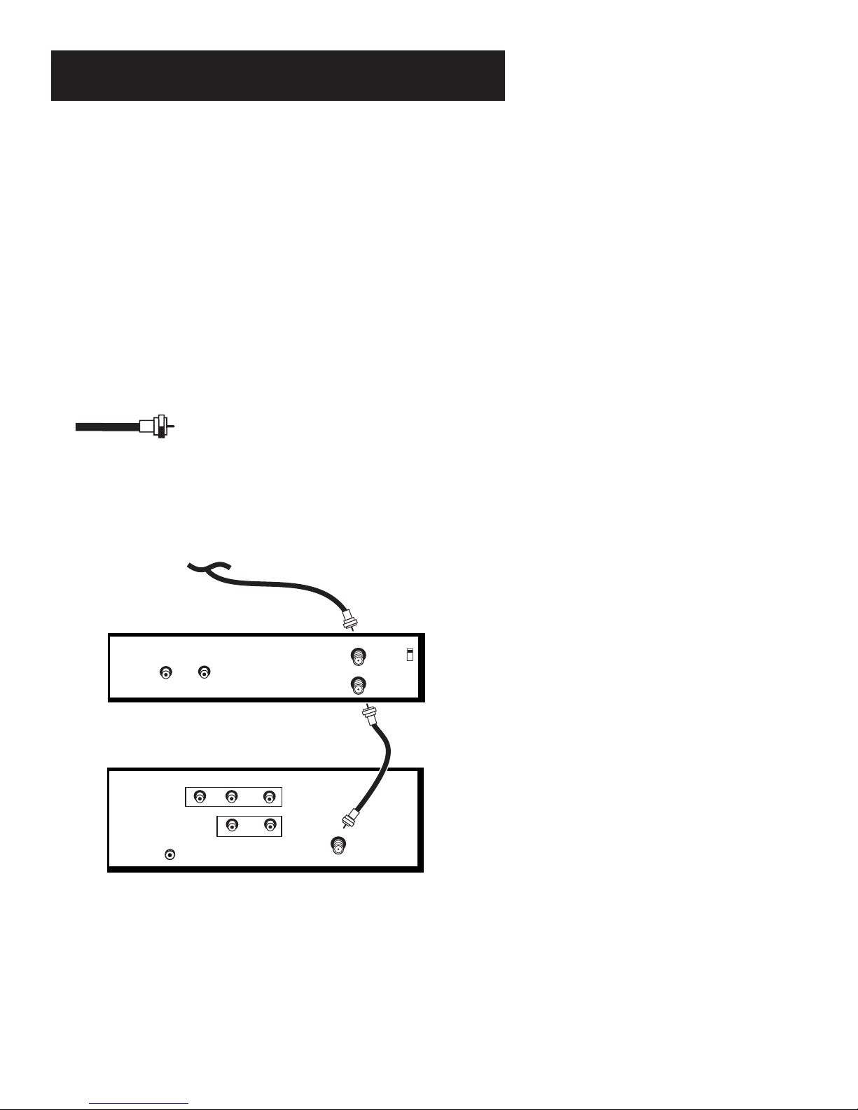
TV Only
This is a basic connection from an antenna or cable system to
your TV. Connect the cable into the Cable/Antenna jack as shown.
Important Stand Information
CAUTION: Choose the location for
your TV carefully. Take precautions
that the stand or other furniture on
which the TV is placed is properly
located (see Important Safeguards
sheet) and of adequate size and
strength to prevent the TV from
accidentally being tipped over,
pushed off, or pulled off. This could
cause damage to the TV and/or
personal injury.
Before You Connect
Protect against power surges:
• Connect all components before
plugging any power cords into the
wall outlet.
• Turn off the TV and/or component
before connecting or disconnecting
any cables.
• Make sure all antennas and cables
are properly grounded. Refer to the
Important Safeguards sheet
packed with your TV.
Cables
You will use the following cable to make your connection:
Coaxial Cable: These cables carry audio and
video signals to the TV from an antenna, cable, or
cable box.
CABLE, CABLE BOX, OR ANTENNA
TV
R
R
AUDIO
L / MONO
L
VCR
CONTROL
VIDEO
4
IN
OUT
CABLE/
ANTENNA
Your TV may be different!
The MG25326 does not have audio
outputs, while the MG31526 has an
additional S-Video input. Read
Advanced Connections
in this section
for more information about possible
connections.
Once you have completed this
connection you may skip to Step 3.
Page 7
Setup and Connections
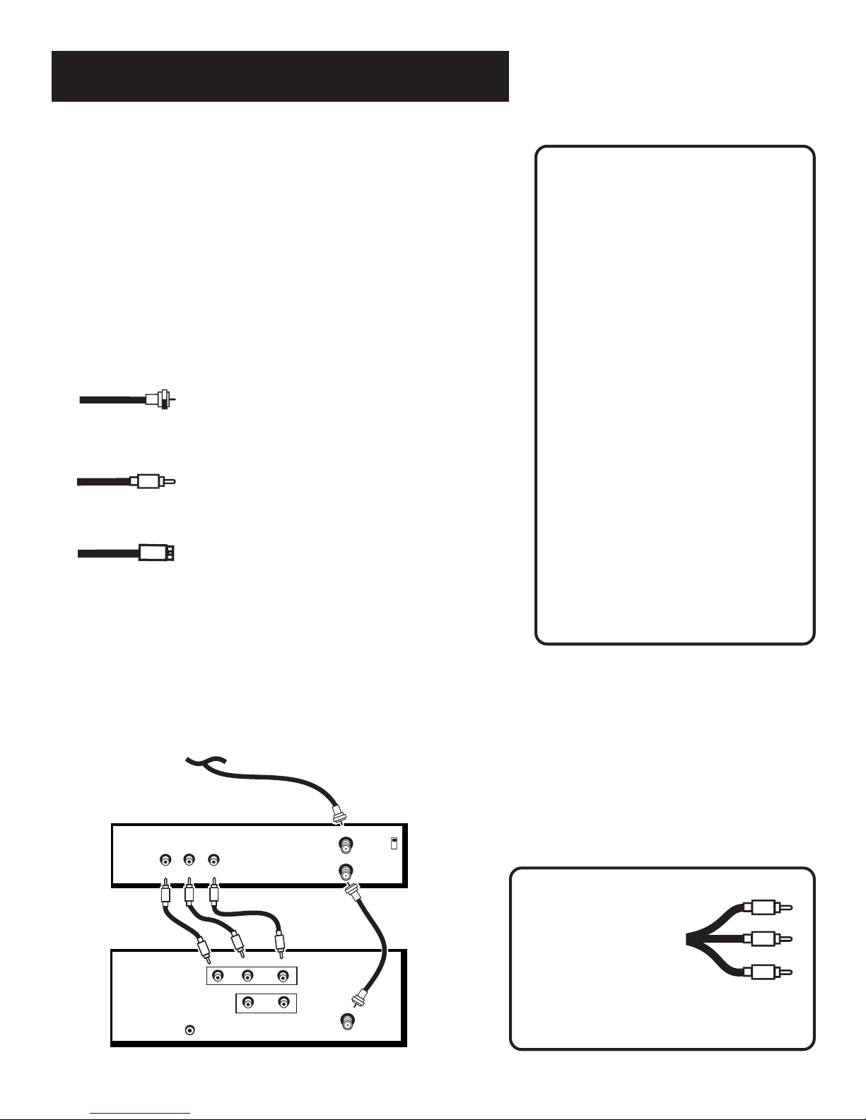
The Basic Connection
The basic connection below (TV and VCR) is the most common
connection and is therefore used to illustrate a single
component connection with your TV. For better sound and
picture quality and multiple component connection information
refer to the next section,
Cables
You will use the following type of cable to make your
connection:
Advanced Connections
.
Coaxial Cables: In this connection, two
coaxial cables are used: one connects from
an antenna, cable, or cable box to the VCR,
and one connects from the VCR to the TV.
These cables carry both audio and video
signals.
CABLE, CABLE BOX, OR ANTENNACABLE, CABLE BOX, OR ANTENNA
VCR 1
VIDEO
IN FROM ANT
OUT
OUT TO TV
AUDIO
CH3
CH4
TV
R
R
AUDIO
L / MONO
L
IN
OUT
CABLE/
ANTENNA
VCR
CONTROL
VIDEO
Once you have completed this connection you may skip to
Step 3.
How to View the VCR
To watch the VCR in this connection tune
TV to Channel 3 or 4.
Later, in the
you will program the TV to automatically
tune to Channel 3 or 4 when you turn on
the VCR.
Interactive Setup
section
5
Page 8

Setup and Connections
Advanced Connections
Advanced connections give you better sound and video by
separating the audio and video signals and enabling you to
connect multiple components.
This section describes the types of inputs available on the back
of your TV and suggests ways you can use them for optimum
performance.
Back of the TV
The number of jacks on the back panel of your TV depends on
the model number of your TV. Find out the model number of
your TV and look for its corresponding diagram either below or
on the next page. When connecting A/V cables, be sure to
connect corresponding OUTPUTS and INPUTS (Video to Video,
Right Audio to Right Audio, etc.).
Model MG27526
Once you have made your
connections you will need to
program the TV to tune to the
correct Video INPUT channel in order
to see and hear audio and video from
the component. You will program
this later in the
Interactive Setup.
R
R
AUDIO
L / MONO
L
IN
OUT
CABLE/
ANTENNA
VIDEO
1
2
3
1
VIDEO and AUDIO IN Use these input jacks to connect a
VCR
CONTROL
VCR, Laserdisc player, DVD player, satellite receiver or
Internet Access Device. To view the component connected to
VIDEO, use the INPUT button on the remote.
2
AUDIO OUT Use these output jacks to connect to an
audio receiver or amplifier for variable controlled or fixed
level stereo output.
3
VCR CONTROL This jack is for a feature not available in
your market at the time of this printing. The circuitry that
would allow this feature to work has been disabled in your
TV.
4
CABLE/ANTENNA Takes the signal input from a cable,
cable box, or an off-air antenna. Can also be used for basic
component connections.
4
6
Page 9

Setup and Connections
Model MG25326
R
AUDIO
L / MONO
IN
CABLE/
ANTENNA
VIDEO
1
VCR
2
1
VIDEO and AUDIO IN Use these input jacks to connect a
CONTROL
VCR, Laserdisc player, DVD player, satellite receiver or
Internet Access Device. To view the component connected to
VIDEO, use the INPUT button on the remote.
2
VCR CONTROL This jack is for a feature not available in
your market at the time of this printing. The circuitry that
would allow this feature to work has been disabled in your
TV.
3
CABLE/ANTENNA Takes the signal input from a cable,
cable box, or an off-air antenna. Can also be used for basic
component connections.
Model MG31526
R
R
AUDIO
L / MONO
L
IN
OUT
S-VIDEO
CABLE/
ANTENNA
1
VIDEO
2
VCR
3
CONTROL
3
5
4
1
VIDEO and AUDIO IN Use these input jacks to connect a
VCR, Laserdisc player, DVD player, satellite receiver or
Internet Access Device. To view the component connected to
VIDEO, use the INPUT button on the remote.
2
AUDIO OUT Use these output jacks to connect to an
audio receiver or amplifier for variable controlled or fixed
level stereo output.
3
VCR CONTROL This jack is for a feature not available in
your market at the time of this printing. The circuitry that
would allow this feature to work has been disabled in your
TV.
4
CABLE/ANTENNA Takes the signal input from a cable,
cable box, or an off-air antenna. Can also be used for basic
component connections.
5
S-VIDEO This optional connection is only available on the
MG31526. S-Video connections can be used for better video
quality picture.
7
Page 10
Setup and Connections
Sample Connections
The following are sample connection scenarios you may
encounter when connecting components to your TV.
Note: those components which offer an S-Video
connection, such as DVD, VCR or satellite receivers, must
match their S-Video connection with their audio INPUT
connection.
Cables
You will use the following types of cables to make your
connection:
Coaxial Cables: Carries the signal
from the antenna or cable directly to
the television or through a cable box,
as needed by your cable system.
Audio/Video Cables: Carries audio
and video from a component to the
TV.
S-Video Cable: Carries video from
an S-Video capable component which
provides best picture quality. Note:
Only the MG31526 has an S-Video
connection.
TV and Stereo VCR
Cautions:
Position Cables to Avoid Audio Hum
or Interference
• Insert all cables firmly into jacks.
• Place the audio/video cables to the
sides of the TV’s back panel
instead of straight down the
middle.
• Try not to coil any twin-lead cables
and keep them away from the
audio/video cables.
Protect Your Components From
Overheating
• Do not block ventilation holes in
any of the components. Arrange
the components so that air can
circulate freely.
• Do not stack components.
• Allow adequate ventilation when
placing your components in a
stand.
• Place an amplifier on the top shelf
of the stand so heated air rising
from it will not flow around other
components.
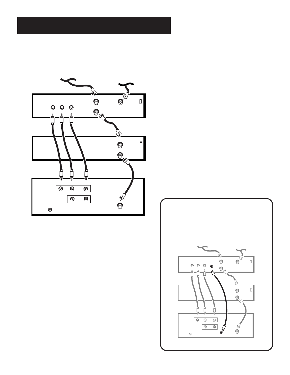
Compared to the Basic Connection, using Audio/Video
and S-Video (if available) cables will enhance the sound
and picture quality from a component.
CABLE, CABLE BOX, OR ANTENNA
VCR 1
TV
VIDEO
OUT
R
VCR
CONTROL
L
VIDEO
R
R
AUDIO
L / MONO
L
IN FROM ANT
OUT TO TV
IN
OUT
CH3
CH4
CABLE/
ANTENNA
8
How to View Your VCR
To watch the VCR in this connection,
press TV to put the remote control into
TV mode, then press INPUT to toggle to
the video (VID) inputs.
In the
Interactive Setup
program the TV to automatically tune to
the VID input channel when you turn on
the VCR.
Most Audio/Video cables
are combined into one
cable with three
heads on each end.
We show individual
cables in these sample
connections. Either may
be used, but you must be
sure to connect Video to Video, Right to
Right and Left to Left.
section you can
Video (yellow)
Right Audio (red)
Left Audio (white)
Page 11
Setup and Connections
SATELLITE RECEIVER
VCR 1
TV
S-VIDEO
L
R
VIDEO
OUT
IN FROM ANT
OUT TO TV
SATELLITE
IN
CH3
CH4
IN FROM ANT
OUT TO TV
CH3
CH4
VIDEO
R
L / MONO
S-VIDEO
AUDIO
R
L
CABLE/
ANTENNA
VCR
CONTROL
IN
OUT
SATELLITE SIGNAL
CABLE, CABLE BOX, OR ANTENNA
TV, Satellite Receiver and Stereo VCR
CABLE, CABLE BOX, OR ANTENNA
SATELLITE SIGNAL
How to View Your Components
SATELLITE RECEIVER
OUT
VIDEO
R
L
VCR 1
TV
VIDEO
VCR
CONTROL
R
R
AUDIO
IN FROM ANT
OUT TO TV
L / MONO
L
IN
OUT
SATELLITE
IN
IN FROM ANT
OUT TO TV
CABLE/
ANTENNA
CH3
CH4
CH3
CH4
To watch the satellite receiver in this
connection, press TV to put the remote control
into TV mode, then press INPUT to scroll
through the video input channels until you
tune to VID (or S-VID, if you have the MG31526
and have used an S-Video connection) input.
To watch the VCR in this connection, enter 03
to tune to the VCR channel.
In the
Interactive Setup
you can program the
TV to automatically tune to the correct input
channel when you turn on your component.
IMPORTANT: For Model MG31526
The MG31526 has an additional S-Video
input jack. S-Video connections provide
better video quality. The diagram below
shows a sample connection using this jack.
9
Page 12
Setup and Connections
SKIP
REC PAUSE
PLAY
STOP
REW FF
DISPLAY
V
C
R
2
¥
L
D
A
U
D
I
O
CHAN
P
O
W
E
R
V
C
R
1
ł
S
A
T
¥
C
A
B
L
E
T
V
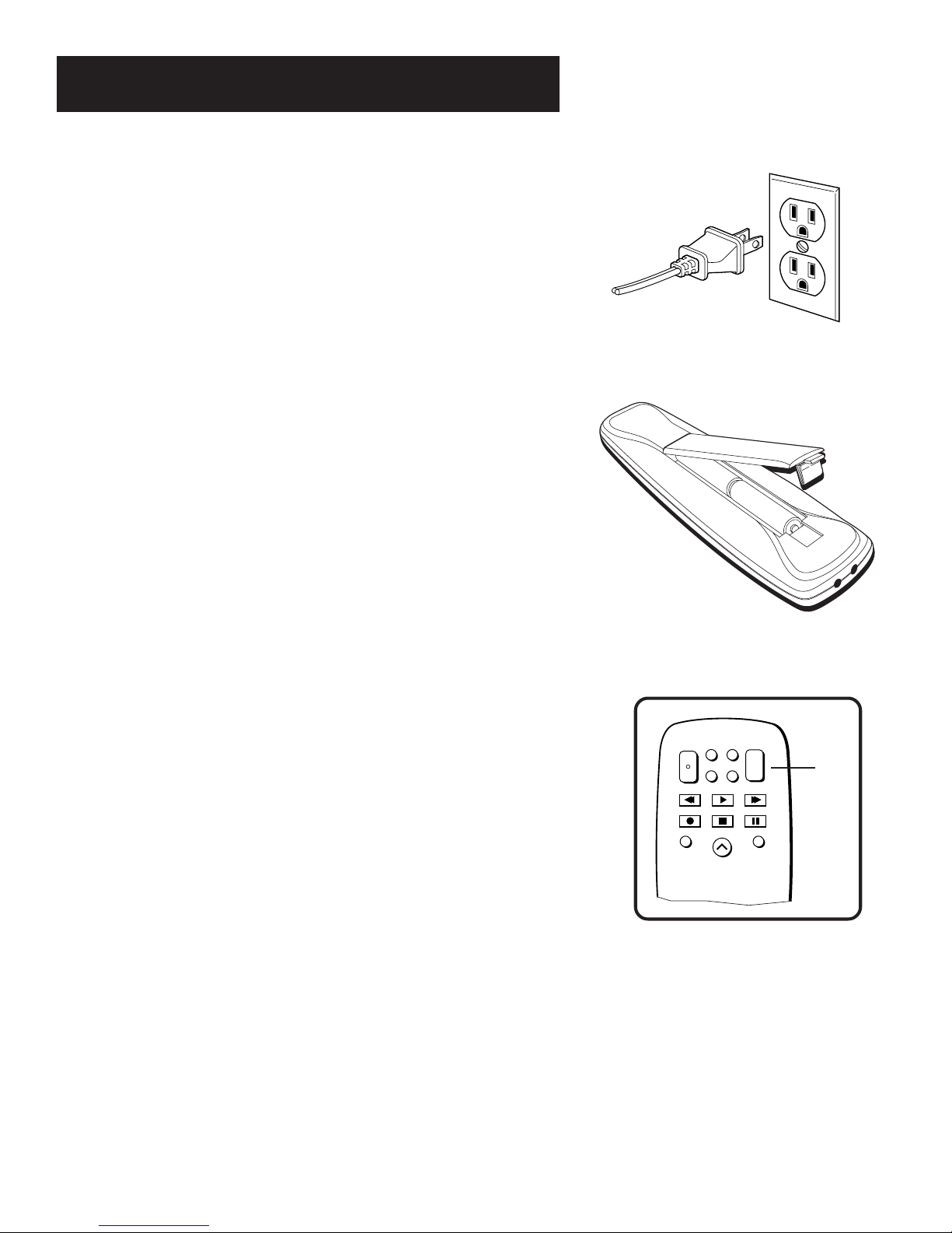
Step 3: Plug in the TV
Plug the end into the wall outlet, matching the wide blade of the
plug with the wide slot in the outlet. Be sure to insert the plug
completely.
Step 4: Place Batteries in Remote
• Remove the battery compartment cover from the back of the
remote.
• Insert fresh batteries. Make sure that the polarities (+ and -)
are aligned correctly.
• Replace the cover.
Step 5: Turn On the TV
Press TV on the remote, or press POWER on the TV itself.
Pressing the TV button not only turns on the TV, but puts the
remote into TV mode, so that the buttons on the remote will
control TV functions.
Step 6: Program the TV
Proceed to the next section,
setup routine walks you through the steps needed to fully
configure the TV. The first steps ask you to select your preferred
language for the menu system and to begin the auto channel
search, which puts available cable TV or antenna signals into the
TV’s memory.
Interactive Setup
. The interactive
TV
10
Page 13

Interactive Setup
There’s an On-Screen Setup
Routine
The interactive setup routine helps you through the
steps needed to configure the TV:
• Select a menu language
• Search for available channels
• Set the time
• Set the VCR1 channel
• Set the VCR2 channel
• Set the SAT/CABLE channel
• Make the channel list and labels
SETUP AND
1
CONNECTIONS
➣
INTERACTIVE SETUP
2
➣➣
USING THE REMOTE
3
MENUS AND FEATURES
4
➣
REFERENCE
5
11
Page 14

Interactive Setup
Using Point and Select Navigation
You only need to know one rule when using the remote to access
on-screen menus and control panels: point and select. The point
and select method has two steps.
1. Point to a menu item using the MOVE arrows on the remote.
To point up or down, press the up or down arrows. To point left
or right, press the left or right arrows.
2. Select a menu item by pressing MENU•PROG.
Selecting an item tells the TV’s menu system to go ahead and
make the change or go to a place you have indicated.
Entering Setup
The first screen of the Interactive Setup appears automatically
when you turn on your TV for the first time or after a power outage.
1. Press MENU•PROG to begin setup or CLEAR to exit.
SETUP
When first used or after a power
outage, your television needs
to be set up.
Would you like to begin now?
Press MENU to begin setup or
Press CLEAR to exit.
You can also access the Interactive Setup through the Main menu:
PROG
MENU
•
CLEAR
RESET
MOVE
Point and Select buttons
1. Press MENU•PROG to bring up the Main menu.
TV MAIN MENU
1 Audio
2 Picture Quality
3 Screen
4 Channel
5 Time
6 Parental Control
7 Setup
0 Exit
2. Point to
Setup
and press MENU•PROG . The first Setup screen
comes up, asking you to confirm that you want to begin.
12
You can also select a menu item by
entering the item number with the
number buttons on the remote.
Press CLEAR at any time to remove
all displays from the screen and
return to TV viewing.
Many VCR user manuals refer to a
PROGRAM button. The MENU•PROG
button on this remote works as a
PROGRAM button in VCR mode for
GE, RCA and proscan VCRs.
Page 15

Interactive Setup
SETUP
Would you like to begin Setup
now?
1 Begin setup now
2 Cancel setup
3. Point to
Begin setup now
and press MENU•PROG.
Selecting a Language
The first part of the setup routine asks you to select your preferred
language for the menu system.
SETUP
Select the language to be used
in these menus.
1 English
2 Español
3 Français
1. Point to your preferred language for the menu system.
2. Press MENU•PROG to select that language.
Auto Channel Search
The next part of the setup routine asks you if you want the TV to
search for all channels viewable through your antenna or cable TV
system. This is sometimes called “auto programming.”
SETUP
Would you like the TV to search
for all available channels?
1 Search for channels
2 Skip this step
1. Press MENU•PROG to tell the TV to begin searching for
channels. When done, press MENU•PROG to continue.
If you skip Auto Channel Search now,
you can access it later through the
Channel menu. See
Features
for more details.
Menus and
13
Page 16

Interactive Setup
SET TIME
:
AM
Enter
01 to 12
for the hour.
Press MENU to exit.
Setting the Time
The next step in the Interactive Setup lets you set the time of
day.
1. Press MENU•PROG to bring up the Set Time control panel.
2. Use the left and right arrows to point to the hour and
minutes spaces. Use the digits to enter the numbers and the
up and down arrows to change from AM to PM.
3. Press MENU•PROG to continue.
Setting the VCR1 Channel
(Auto Tuning)
The next step lets you set the VCR1 channel. When you set the
VCR1 channel, you’re telling the TV what channel to tune to
when you press the VCR1 button on the remote. This is called
auto tuning.
Indicate which input you used to connect the VCR. If you don’t
have a VCR1 component connected to the TV, skip this step or
select
Not Connected
more, see Auto Tuning in the
1. Press MENU•PROG to bring up the VCR1 choice list.
from the VCR1 Channel choice list. (For
Menus and Features
section.)
SETUP
Would you like to set the time
on the TV?
1 Set time
2 Skip this step
SETUP
Would you like to use a VCR
with your TV?
1 Use TV with a VCR
2 Skip this step
SET VCR1 CHANNEL
1 Not connected
2 Channel 3
3 Channel 4
4 Video Input
2. Point to the choice that matches the way you have your VCR
connected to the TV.
3. Press MENU•PROG to continue.
14
Page 17

Interactive Setup
SET SAT/CABLE CHANNEL
1 Not connected
2 Channel 2
3 Channel 3
4 Channel 4
5 Video Input
Setting the VCR2 Channel
(Auto Tuning)
The next step lets you set the VCR2 channel. When you set the
VCR2 channel, you’re telling the TV what channel to tune to
when you press the VCR2•LD button on the remote.
Indicate which input you used to connect a second VCR, DVD
player or Laserdisc player. If you don’t have a second VCR, DVD
player or Laserdisc player connected to the TV, skip this step or
select
Not Connected
more, see Auto Tuning in the
from the VCR2 Channel choice list. (For
Menus and Features
section.)
1. Press MENU•PROG to bring up the VCR2 choice list.
2. Point to the choice that matches the way you have your
second VCR connected to the TV.
3. Press MENU•PROG to continue.
Setting the DVD Channel
(Auto Tuning)
The remote control that came packed with your TV does not
have a button corresponding to this feature. This feature does,
however, function with other types of universal remote controls.
If you are setting up your TV for the first time, go ahead and skip
this step or select
list. (For more, see Auto Tuning in the
section.)
Not Connected
from the DVD channel choice
Menus and Features
SETUP
Would you like to use a second
VCR with your TV?
1 Use TV with VCR 2
2 Skip this step
SET VCR2 CHANNEL
1 Not connected
2 Channel 3
3 Channel 4
4 Video Input
SETUP
Would you like to use a DVD
with your TV?
1 Use TV with DVD
2 Skip this step
Setting the SAT/CABLE Channel
(Auto Tuning)
The next step lets you set the SAT/CABLE channel. When you set
the SAT/CABLE channel, you’re telling the TV what channel to
tune to when you press the SAT•CABLE button on the remote.
Indicate which input you used to connect a satellite receiver or a
cable box. If you don’t have a satellite receiver or cable box
connected to the TV, skip this step or select
the SAT/CABLE Channel choice list. (For more, see Auto Tuning
in the
Menus and Features
1. Press MENU•PROG to bring up the SAT/CABLE choice list.
2. Point to the choice that matches the way you have your
satellite receiver or cable box connected to the TV.
3. Press MENU•PROG to continue.
section.)
Not Connected
SETUP
Would you like to use a cable
box or satellite unit with your
TV?
1 Use with cable or satellite
2 Skip this step
from
15
Page 18

Interactive Setup
Labeling the Channels
This last step in the Interactive Setup lets you edit your channel
list and label your channels. (For more, see List and Labels in
the
Menus and Features
1. Press MENU•PROG to bring up the List and Labels control
panel.
2. Use the left and right arrows to point to the three different
areas of the control panel (called “fields”).
3. Use the up and down arrows to scroll through the numbers
and letters and select
may wish to refer to the call letters listed in your
newspaper’s TV section for ideas on labeling the channels.
4. Repeat this process for each of your channels. Then press
MENU•PROG to continue. The TV can store up to 27 labels
in memory.
section.)
Yes
or
No
in the Normal List field. You
What Now?
Now that you’ve finished the interactive setup, you can sit back,
relax, and enjoy the TV. Or...
SETUP
Would you like to name each
channel?
1 Name channels
2 Skip this step
LIST AND LABELS
Chan Normal Chan
# List Label
59 Yes ------
Use ^ or v, keypad, or CH ^/v
to set channel, MENU to exit.
Program the Remote
Since you’ve gone this far, you can take a few minutes to
program the remote to control your VCR, Laserdisc player,
Satellite Receiver, or other components. To find out how to
program the remote, go to the next section.
Use the CH␣ (channel up) or CH␣
(channel down) buttons to change
channels in the Chan # field. This
works even if you’re not in the Chan
# field. Or, enter the channel number
directly using the number buttons on
the universal remote. To enter a
number greater than 99, press and
hold “1” to enter the hundreds digit,
then press the two remaining
numbers.
The list and labels feature can also be
accessed from the Channel menu.
Because this procedure can be time
consuming, feel free to skip this step
and come back to it later.
16
Page 19

Using the Remote
How to use Your Universal
Remote
This section defines the buttons of the remote
and how to program it to control other
components.
The universal remote can be programmed to
control most brands of remote controllable
VCRs, satellite receivers, and cable boxes. If
you have an GE, RCA, or PROSCAN
component, you probably don’t need to
program it at all.
SETUP AND
1
CONNECTIONS
➣
INTERACTIVE SETUP
2
➣➣
USING THE REMOTE
3
MENUS AND FEATURES
4
➣
REFERENCE
5
Modes of Operation
Because this universal remote can
control several different components
(Laserdisc player, VCR, Cable Box,
etc.), it uses operational modes
triggered by the component
buttons. For example if you want
the remote to control the TV, you
would press the TV button to put
the remote into TV mode before you
could control the TV.
17
Page 20

Using the Remote
INPUT ANTENNA
SKIP
PREV CH
REC PAUSE
PLAY
STOP
REW FF
CLEAR
MENU
•
PROG
RESET
MOVE
MUTE
DISPLAY
1
456
32
798
0
V
C
R
2
•
L
D
A
U
D
I
O
VOL
CHAN
CHAN
VOL
P
O
W
E
R
V
C
R
1
ł
S
A
T
•
C
A
B
L
E
T
V
Remote Buttons
POWER When in TV mode, turns TV on and off. If in another
device mode (VCR, Laserdisc, Satellite, etc.) and programmed,
will turn the device on and off.
VCR1 Puts the remote in VCR mode and if autotuning is
enabled, it will turn on the TV and tune to the correct channel.
VCR2•LD Puts the remote in VCR2 mode and if autotuning is
enabled, it will turn on the TV and tune to the correct channel.
VCR2•LD can only be programmed for one component: either a
VCR or Laserdisc player.
SAT•CABLE Puts the remote in SAT•CABLE mode and if
autotuning is enabled, it will turn on the TV and tune to the
correct channel.
AUDIO Puts the remote in Audio mode.
TV Turns on the TV and puts the remote in TV mode. Also
displays channel information.
REW, PLAY, FF, REC, STOP, PAUSE If programmed,
provides transport control for some remote-controllable VCRs,
Laserdisc players, tape decks, and CD players.
DISPLAY Brings up channel information. Also clears menus
from the screen.
SKIP Press once before changing channels and the TV will
wait 30 seconds before returning you to the original channel.
Press repeatedly to add more time (each press adds another 30
seconds).
CH or CH Scans up or down through the current channel
list. Press once to change the channel up or down; press and
hold to continue changing channels.
VOL – or VOL + Decreases or increases the TV’s volume.
MUTE Reduces the TV’s volume to its minimum level. Press
again to restore the volume.
PREV CH Returns you to the previous channel.
(0-9) Number Buttons Enters channel numbers and time
settings directly though the remote control. To enter a two-digit
channel, press the two digits. To enter a three-digit channel,
press and hold the first digit, then add the second two. Example:
to tune to channel 123, press and hold 1, press 2, then press 3.
18
Page 21

Using the Remote
INPUT In TV mode, press to toggle through the available input
sources (VID/SVID and the current channel).
ANTENNA Functions as TV/VCR button in VCR mode and TV/
receiver button in SAT•CABLE mode.
CLEAR Removes any menu or display from the screen and
returns you to TV viewing. For GE, RCA and PROSCAN VCRs,
this button also clears items from the VCR clock and timer
programs.
MENU•PROG Brings up the Main menu and selects
highlighted items. When in VCR mode, it functions as a
PROGRAM button for GE, RCA and PROSCAN VCRs.
RESET Resets picture quality controls to the
Picture Control Preset. Point and select to choose a different
Picture Control Preset. Also used to reset the settings in a menu.
MOVE (Arrows) Used to point to different items in the menu
system. Also used to adjust the menu controls.
Bright Lighting
Using the INPUT Button
Use the INPUT button to toggle through the available input
sources (VID and the current channel) and view the component
you have connected to the TV.
1. Press TV to place the remote in TV mode. Make sure that the
component you want to view is turned ON.
2. Press INPUT to tune to the available input source and view
the component.
3. Press INPUT again to tune back to the channel you were
previously watching.
Modes of Operation
Because this universal remote can
control several different components
(Laserdisc player, VCR, Cable Box,
etc.), it uses operational modes
triggered by the component
buttons. For example, if you want
the remote to control the TV, you
would press the TV button to put
the remote into TV mode before you
could control the TV.
19
Page 22

Using the Remote
Programming the Remote
The universal remote can be programmed to control most
brands of remote controllable VCRs, receivers, etc. The remote
is already programmed to control most RCA, GE and
PROSCAN TVs, VCRs, Laserdisc players and Satellite Receivers.
Testing the Remote
To determine whether the universal remote needs to be
programmed, turn a device on, such as a VCR, point the remote
at the VCR, and press the VCR1 button. Then press POWER or
CH (channel up) or CH (channel down) to see if the VCR
responds to the remote commands. If not, the remote needs to
be programmed.
Programming the Remote to Control a VCR, Laserdisc
player, Satellite Receiver or Cable Box
Follow these steps to program your universal remote to control
a VCR, Laserdisc player, Satellite Receiver or Cable Box:
1. Turn on the component to be programmed.
2. Look up the brand and code number(s) for the component
on the code list on the last page of this section,
Remote
.
3. Press and hold the button on the remote you want to
program.
4. Enter the code from the code list.
5. Release button, and then press POWER to see if the
component responds to the remote commands. If it doesn’t,
try pressing the component button and then POWER again.
6. If you get no response, repeat these steps using the next
code listed for your brand, until the component responds to
the remote commands.
Using the
S
ł
A
1
T
R
•
C
C
V
R
E
W
O
P
R
C
V
VOL
1
•
2
CHAN
CHAN
A
B
L
E
T
V
D
L
A
U
D
I
O
VOL
32
456
798
0
You’ll use these buttons when you
program the remote to control any
device.
The remote may not operate all
models of all brands.
20
Page 23

Using the Remote
Programming the Remote to Control
an RCA Audio Device:
Your remote controls only RCA audio equipment such as an
audio receiver or amplifier—it does not control other brands of
audio equipment. Also, the remote may need to be
programmed for your equipment. This remote may not operate
all of the components listed at the end of this section. Use the
codes at the end of this section or on the sheet packed in with
your remote.
1. Turn on the component to be programmed.
2. Look up your brand and its code number(s) on the code list.
3. Press and hold the AUDIO button.
4. Enter the code from the code list.
5. Release the AUDIO button and press POWER or CH
(channel up) or CH (channel down) to see if the audio
device responds to the remote commands.
Using the Remote to Control a Device
Once the remote has been programmed successfully, you are
ready to use it to control your devices.
Modes of Operation
Because this universal remote can
control several different components
(Laserdisc player, VCR, Cable Box,
etc.), it uses operational modes
triggered by the component buttons.
For example, if you want the remote
to control the TV, you would press
the TV button to put the remote into
TV mode before you could control
the TV.
To operate the device:
1. Press the device button (TV, VCR1, VCR2•LD, or SAT•CABLE)
to set the remote to control the device.
2. Press POWER to turn the device on or off.
3. Use the remote buttons that apply to that device.
Front Panel
If you cannot locate your remote, you can use the front panel of
your TV to operate many of the TV’s features.
MENU Brings up the Main menu. When in the menu system, it
selects highlighted items. Also returns you to the previous
menu.
CH Scans down through the current channel list. In the menu
system, it points down to items and adjusts menu controls.
CH Scans up through the channel list. In the menu system, it
points up to items and adjusts menu controls.
VOL – Decreases the volume. When in the menu system,
VOL – is used to point left to items and adjust menu controls.
VOL + Increases the volume. When in the menu system,
VOL + is used to point right to items and adjust menu controls.
POWER Turns the TV on and off.
+
MENU POWER
The front panel above shows a
typical button layout. The exact look
of the buttons may be different from
those on the front of your TV.
The Front Panel Block feature
disables all front panel buttons if
Parental Controls are locked. For
more information, see Parental
Control, in the
section.
CH
CH
VOL
Menus and Features
VOL
–
21
Page 24

Using the Remote
VCR
Admiral ......................................................................... 2131
Adventura..................................................................... 2026
Aiko ............................................................................... 2027
Aiwa .................................................................... 2002, 2026
Akai .... 2003, 2004, 2005, 2007, 2008, 2111,2112, 2113
American High ............................................................ 2021
Asha ...............................................................................2013
Audio Dynamics .............................................. 2009, 2010
Audiovox ......................................................................2014
Bell & Howell...............................................................2011
Beaumark ..................................................................... 2013
Broksonic .......................................................... 2012, 2025
Calix .............................................................................. 2014
Candle ......... 2013, 2014, 2015, 2016, 2017, 2018, 2019
Canon ...................................................... 2021, 2022, 2114
Capehart ............................................................ 2020, 2110
Carver ........................................................................... 2062
CCE .................................................................... 2027, 2061
Citizen 2013, 2014, 2015, 2016, 2017, 2018,2019,2027
Colortyme ................................................................... 2009
Colt ................................................................................ 2061
Craig ............................................. 2013, 2014, 2023, 2061
Curtis-Mathes ........................... 2000, 2002, 2009, 2013,
................................. 2016, 2018, 2021, 2022, 2024, 2115
Cybernex ...................................................................... 2013
Daewoo ...... 2015, 2017, 2019,2025, 2026, 2027, 2028,
Daytron......................................................................... 2110
Dbx ..................................................................... 2009, 2010
Dimensia ....................................................................... 2000
Dynatech ........................................................... 2002, 2026
Electrohome ..................................................... 2014, 2029
Electrophonic .............................................................. 2014
Emerson ................................................. 2002, 2012,2014,
............ 2015, 2021, 2024, 2025,2026,2029, 2030, 2032,
2033, 2034, 2035, 2036, 2037, 2038, 2039, 2040, 2041,
2042, 2044, 2045, 2047, 2065, 2105, 2113, 2116, 2117,
Fisher . 2011, 2023, 2048, 2049, 2050, 2051, 2052,2118
Fuji ...................................................................... 2021, 2119
Funai ................................................................... 2002, 2026
Garrard ......................................................................... 2026
GE ..... 2000, 2001, 2013, 2021, 2022, 2053, 2115, 2120
Goldstar ............................ 2009, 2014, 2018, 2054, 2121
Gradiente ..................................................................... 2026
Harley Davidson ......................................................... 2026
Harman Kardon ..........................................................2009
Harwood ...................................................................... 2061
Headquarter ................................................................ 2011
Hitachi2002, 2055, 2056, 2057, 2107, 2111, 2120, 2122
HI-Q .............................................................................. 2023
Instant Replay .............................................................. 2021
JCL ................................................................................. 2021
JC Penney ............. 2009, 2010, 2011, 2013, 2014, 2021,
.......... 2022, 2055, 2056, 2058, 2059, 2060, 2107, 2118
Jensen ...................................................... 2055, 2056, 2111
JVC ............... 2009, 2010, 2011, 2018, 2058, 2111, 2123
Kenwood .............. 2009, 2010, 2011, 2016, 2018, 2058,
KLH ............................................................................... 2061
Kodak ................................................................. 2014, 2021
Lloyd ................................................................... 2002, 2026
Logik .............................................................................. 2061
LXI ................................................................................. 2014
Magnavox .... 2021, 2022, 2062, 2063, 2104, 2108, 2124
Magnin ........................................................................... 2013
Marantz .................................................. 2009, 2010, 2011,
.................................. 2016, 2018, 2021, 2058, 2062,2064
Marta ............................................................................. 2014
Masushita ...................................................................... 2021
MEI ................................................................................. 2021
Memorex .......................................................... 2002, 2011,
..................... 2013, 2014, 2021, 2023, 2026, 2104, 2131
MGA ........................................................ 2029, 2065, 2113
MGN Technology ........................................................ 2013
Midland ......................................................................... 2053
Minolta .................................................... 2055, 2056, 2107
Mitsubishi .. 2029, 2055, 2056, 2065, 2066, 2067, 2069,
.......... 2070, 2071, 2072, 2073, 2074, 2106, 2113, 2123
Montgomery Ward .......................................... 2075, 2131
Motorola........................................................... 2021,2131
2110
2130
2111,2123
MTC .......................................................... 2002, 2013, 2026
Multitech ................. 2002, 2013, 2016, 2026, 2053, 2061
NEC .................................... 2009, 2010, 2011, 2016, 2018,
....................... 2058, 2064, 2076, 2078, 2079, 2111, 2123
Nikko ............................................................................... 2014
Noblex ............................................................................ 2013
Olympus ......................................................................... 2021
Optimus ............................................................... 2014, 2131
Optonica ......................................................................... 2096
Orion .............................................................................. 2035
Panasonic ................. 2021, 2022, 2109, 2125, 2126, 2127
Pentax ................................. 2016, 2055, 2056, 2107, 2120
Pentex Research ........................................................... 2018
Philco .............................................. 2021, 2022, 2062, 2063
Philips ............................................. 2021, 2062, 2096, 2124
Pilot ................................................................................. 2014
Pioneer ................................ 2010, 2055, 2080, 2081, 2123
Portland ......................................... 2016, 2017, 2019, 2110
PROSCAN .......................................................... 2000, 2001
Protec .............................................................................. 2061
Pulsar ............................................................................... 2104
Quarter .......................................................................... 2011
Quartz ............................................................................. 2011
Quasar ...................................................... 2021, 2022, 2125
RCA .................................... 2000, 2001, 2003, 2013, 2021,
.............. 2055, 2056, 2082, 2083, 2084,2085, 2086,2087,
.............. 2088, 2089, 2090, 2091, 2107, 2115, 2120, 2125
Radioshack/Realistic .................... 2002, 2011, 2013, 2014
. 2021, 2022, 2023, 2026, 2029, 2049, 2050, 2096, 2131
Radix ................................................................................ 2014
Randex ............................................................................ 2014
Ricoh ............................................................................... 2128
Runco .............................................................................. 2104
Samsung ................... 2005, 2013, 2015, 2033, 2053, 2112
Sanky .................................................................... 2131, 2104
Sansui ............................................. 2010, 2092, 2111, 2123
Sanyo ......................................................... 2011, 2013, 2023
Scott ... 2012, 2015, 2025, 2032, 2035, 2038, 2065, 2093,
Sears .................................... 2011, 2014, 2021, 2023, 2048,
......................... 2049, 2050, 2051, 2055, 2056, 2107, 2118
Sharp .............. 2002, 2017, 2029, 2094, 2095, 2096, 2131
Shintom .......................................... 2004, 2056, 2061, 2098
Shogun ............................................................................ 2013
Signature ............................................................. 2002, 2131
Singer ......................................................... 2021, 2061, 2128
Sony .......................... 2002, 2004, 2098, 2099, 2119, 2128
STS ........................................................................ 2021, 2107
Sylvania 2002, 2021, 2022, 2026, 2062, 2063, 2065, 2124
Symphonic ........................................................... 2002, 2026
Tandy .................................................................... 2002, 2011
Tashiko ............................................................................ 2014
Tatung ................................................................... 2058, 2111
TEAC ................................... 2002, 2026, 2058, 2085, 2111
Technics ............................................................... 2021, 2109
Teknika ..................... 2002, 2014, 2021, 2026, 2100, 2129
TMK ........................................................... 2013, 2024, 2047
Toshiba ........... 2015, 2049, 2051, 2055, 2065, 2093, 2116
ToteVision ........................................................... 2013, 2014
Unitech ........................................................................... 2013
Vector Research .......................... 2009, 2010, 2015, 2016
Victor .............................................................................. 2010
Video Concepts ................ 2009, 2010, 2015, 2016, 2113
Videosonic ..................................................................... 2013
Wards .......... , 2002, 2013, 2014, 2015, 2021, 2023, 2026,
.. 2029, 2055, 2056, 2061, 2096, 2101, 2102, 2103, 2107,
XR-1000 ................................................... 2021, 2026, 2061
Yamaha ..................... 2009, 2010, 2011, 2018, 2058, 2111
Zenith .................................. 2004, 2098, 2104, 2119, 2128
2116
2116, 2131
Cable Boxes
ABC ................ 5002, 5003, 5004, 5005, 5006, 5007, 5053
Antronix .............................................................. 5008, 5009
Archer ............................................ 5008, 5009, 5010, 5011
Cabletenna ..................................................................... 5008
Cableview ....................................................................... 5008
Century .......................................................................... 5011
Citizen ............................................................................. 5011
Colour Voice ....................................................... 5012, 5013
Comtronics ......................................................... 5014, 5015
Contec ............................................................................ 5016
Eastern ................................................................................... 5017
Garrard .................................................................................. 5011
GC Electronics ..................................................................... 5009
Gemini ............................................................. 5018, 5019, 5049
General Instrument ................................................. 5003, 5053
Hamlin ........................................ 5020, 5021, 5022, 5035, 5045
Hitachi .................................................................................... 5003
Hytex ...................................................................................... 5002
Jasco ....................................................................................... 5011
Jerrold ........ 5003, 5005, 5007,5018, 5023, 5024, 5046, 5053
Magnavox ............................................................................... 5025
Memorex ............................................................................... 5026
Movie Time ..................................................... 5002, 5027, 5028
NSC .................................................................. 5002, 5027, 5028
Oak .................................................................... 5002,5016, 5029
Panasonic .................................................................... 5048, 5052
Paragon .................................................................................. 5026
Philips ........ 5011, 5012, 5013, 5019, 5025, 5030, 5031, 5032
Pioneer ........................................................................ 5033, 5034
Pulsar ...................................................................................... 5026
RCA .................................................................. 5047, 5049, 5052
Realistic ....................................................................... 5009, 5049
Regal ............................................................................ 5022, 5035
Regency ................................................................................. 5017
Rembrandt ............................................................................ 5003
Runco ..................................................................................... 5026
Samsung ...................................................................... 5014, 5034
Scientific Atlanta .................................. 5006, 5036, 5037, 5038
Signal ............................................................................ 5014, 5018
Signature ................................................................................ 5003
SL Marx .................................................................................. 5014
Sprucer .................................................................................. 5052
Starcom ............................................................ 5007, 5018, 5053
Stargate ....................................................................... 5014, 5018
Starquest ................................................................................ 5018
Tandy ...................................................................................... 5040
Teleview ................................................................................. 5014
Tocom .............................................................. 5004, 5023, 5041
Toshiba ................................................................................... 5026
Tusa ......................................................................................... 5018
TV86 ....................................................................................... 5027
Unika ................................................................ 5008, 5009, 5011
United Artists ....................................................................... 5002
United Cable ........................................................................ 5053
Universal ............................................... 5008, 5009, 5010, 5011
Videoway ............................................................................... 5044
Viewstar ................................................ 5015, 5025, 5027, 5040
Zenith ............................................................... 5026, 5050, 5051
Satellite Receivers
Chapparal ................................................................... 5056, 5057
Drake .......................................................................... 5058, 5059
GE ................................................................................ 5000, 5001
General Instuments ....................................... 5060, 5061, 5062
Panasonic ............................................................................... 5075
Primestar ............................................................................... 5076
PROSCAN ................................................................. 5000, 5001
RCA ............................................................................. 5000, 5001
Realistic .................................................................................. 5063
Sony ........................................................................................ 5072
STS1 ........................................................................................ 5064
STS2 ........................................................................................ 5065
STS3 ........................................................................................ 5066
STS4 ........................................................................................ 5067
Toshiba ........................................................................ 5068, 5073
Uniden .................................................................................... 5069
Audio
(For RCA and Dimensia brands only)
AM/FM ................................................................................... 4003
Aux ......................................................................................... 4004
Phono ..................................................................................... 4005
CD .......................................................................................... 4007
Tape ........................................................................................ 4006
22
Page 25

Menus And Features
The Menu System
This section explores the menus of your TV—beginning
with some information on using menus and control
panels.
Each menu is then outlined and special features are
detailed to help you get the most from your TV.
SETUP AND
1
CONNECTIONS
➣
INTERACTIVE SETUP
2
➣➣
USING THE REMOTE
3
MENUS AND FEATURES
4
➣
REFERENCE
5
23
Page 26

Menus And Features
Menus and Control Panels
Using the buttons on both the remote and front panel enable
you to access and make changes to the menus, control panels,
and choice lists.
Menus and choice lists use the point and select rule to navigate,
but control panels use a variety of methods to adjust features on
your TV. The following pages detail how to use these controls to
customize the functions of your TV.
Menus
The first menu is called the Main menu. Press MENU•PROG on
the remote or MENU on the front panel to bring up the Main
menu:
TV MAIN MENU
1 Audio
2 Picture Quality
3 Screen
4 Channel
5 Time
6 Parental Controls
7 Setup
0 Exit
Menus take you to another menu or a control panel. There are
two ways to select a choice in a menu:
• Point with the arrows and then select with MENU•PROG.
• Press a number button on the remote. For example, in the
Main menu press 3 to go straight to the
Screen
menu.
Exiting a menu
There are three ways to exit a menu:
• Point to
• Press 0 on the remote.
• Press CLEAR. The on-screen displays are cleared from the
screen and you return to TV viewing.
Exit
and press MENU•PROG.
Feel free to explore the menu system.
If you’re ever unsure where you are
in the menu system, or you’re just
plain tired of exploring, press CLEAR
to remove the menus from the screen
and start over again.
24
Page 27

Menus And Features
INPUT ANTENNA
SKIP
PREV CH
REC PAUSE
PLAY
STOP
REW FF
CLEAR
MENU
•
PROG
RESET
MOVE
MUTE
DISPLAY
1
456
32
798
0
V
C
R
2
•
L
D
A
U
D
I
O
VOL
CHAN
CHAN
VOL
P
O
W
E
R
V
C
R
1
ł
S
A
T
•
C
A
B
L
E
T
V
Control Panels
Control panels allow you to adjust the default settings on many
features of your TV. You can choose a setting, enter a number, or
adjust a level such as tint or brightness. There are three types of
control panels: sliders, choice lists, and numeric entry.
Sliders
Sliders are used to make adjustments to a particular control.
To use a Slider in a menu:
1. Press the up or down arrow to select the slider control for
the feature you want to adjust.
2. Press the right or left arrow to adjust the indicator line on
the slider.
BASIC PICTURE CONTROLS
C
ontrast
Color
Tint
Black Level
Sharpness
Press MENU to exit.
Numeric Entry
A numeric entry control panel is used to enter numbers or
letters.
A pointer appears underneath the column you are changing.
01 to 12
Enter
Press MENU to exit.
1. Use the digits to enter a number in the column above the
2. Press the right arrow to move to the next column, then use
3. When you have finished entering information, press
pointer.
the digits to enter a number.
MENU•PROG.
SET TIME
:
for the hour.
Arrows
AM
Pointer
If the control panel is not set to the
current time, use the arrows to go
back over the columns and the digits
to make changes.
You can also enter numbers by using
the up and down arrows on the
remote.
25
Page 28

Menus And Features
Choice Lists
Choice lists are used to choose a particular setting from a list.
When the choice list appears, the highlighted item is the one
that is currently selected, or “in use.”
Point to a choice on a menu and press MENU•PROG to select
that choice. You will then return to the previous screen.
Now that you know how to access the menus and adjust the
control panels, the following pages provide a brief explanation
of all the menu features. The features are organized in order of
their location on the Main menu.
CLOSED-CAPTION MODE
1 CC1
2 CC2
3 CC3
4 CC4
5 Text 1
6 Text 2
7 Text 3
8 Text 4
26
Page 29

Menus And Features
Audio Menu
Mute Press MENU•PROG to reduce the TV’s volume to its
minimum level. Press MENU•PROG again to restore the volume.
Tone Controls Displays the slider controls for adjusting the
TV’s treble, bass and balance.
Audio Processor Displays a choice list of available audio
modes, which control the way the sound comes through your
speakers.
Mono Plays the sound in mono only. Use this setting
when receiving broadcasts with weak stereo signals.
Stereo Splits the incoming stereo audio signal into left
and right channels. Most TV programs and recorded
materials have stereo audio. The TV displays the word
STEREO when you tune to a program that is broadcast in
stereo.
Expanded Stereo Electronically “widens” sound from
stereo broadcasts, stereo VCRs, digital satellite systems,
DVD players, and Laserdisc players for a fuller, more
spacious sound.
Sound Logic Stereo Reduces the annoying blasts in
volume during commercial breaks, and also amplifies softer
sounds in program material. Eliminates the need to
constantly adjust volume control.
TV MAIN MENU
1 Audio
2 Picture Quality
3 Screen
4 Channel
5 Time
1 Mute
6 Parental Controls
2 Tone Controls
7 Setup
3 Audio Processor
0 Exit
4 Audio Output & Speakers
0 Exit
AUDIO
Second Audio Program (SAP) Plays the program’s
audio in a second language, if one is available. The TV
displays the word SAP when you tune to a program that is
broadcast with SAP information. SAP audio is broadcast in
mono. SAP is also used to broadcast a program’s audio with
descriptions of the video for the visually impaired.
Audio Output & Speakers (Not available on the
MG25326) Displays a choice list that lets you turn the TV’s
internal speakers on or off and set the audio outputs to fixedlevel or variable control level.
Variable Output, Speakers On This setting turn the
TV’s speakers on and allows variable output from the TV’s
audio output jacks.
Variable Output, Speakers Off This setting turns the
TV’s speakers off and allows variable output from the TV’s
audio output jacks.
Fixed Output, Speakers Off This setting turns the TV’s
speakers off and allows fixed output from the TV’s audio
output jacks to an external device such as a surround sound
amplifier. With Fixed Output On, the TV’s volume control,
tone controls, and mute are disabled.
27
Page 30

Menus And Features
Picture Quality Menu
Basic Picture Controls Displays the five slider controls for
adjusting the way the picture looks.
Contrast Adjusts the difference between the light and
dark areas of the picture.
Color Adjusts the richness of the color.
Tint Adjusts the balance between the red and green
levels.
Black Level Adjusts the brightness of the picture.
Sharpness Adjusts the crispness of edges in the picture.
When exiting this menu, the
choice list will appear. You can choose either Yes or No. If you
save the settings as a Personal Picture Preset, the TV will store
the settings so you can reselect them easily if someone changes
the settings.
Picture Presets Displays a choice list that lets you select one
of three preset picture settings:
Lighting, Soft Lighting
setting that is best for your viewing environment.
Save Personal Picture Preset
Bright Lighting, Normal
or
Personal Picture Preset
. Choose the
TV MAIN MENU
1 Audio
2 Picture Quality
3 Screen
4 Channel
5 Time
6 Parental Control
7 Setup
0 Exit
PICTURE QUALITY
1 Basic Picture Controls
2 Picture Presets
3 Auto Color
4 Color Warmth
0 Exit
Auto Color Displays a choice list that lets you turn on the
feature that automatically corrects the color of the picture. (This
is especially useful for tracking realistic flesh tone colors as you
switch from channel to channel.) Choose
On
or
Off
, depending
on your preference.
Color Warmth Displays a choice list that lets you set one of
three automatic color adjustments:
of picture colors;
Normal
; and
Warm
Cool
for a more blue palette
for a more red palette of
picture colors. The warm setting corresponds to the NTSC
standard of 6500ºK.
Press the RESET button on the remote
to bring up the Picture Control Presets
choice list. Point to the desired setting;
press MENU•PROG to select it.
28
Page 31

Menus And Features
CLOSED-CAPTION MODE
1 CC1
2 CC2
3 CC3
4 CC4
5 Text 1
6 Text 2
7 Text 3
8 Text 4
SCREEN
1 Closed-Caption Display
2 Closed-Caption Mode
3 Menu Language
0 Exit
Screen Menu
Closed-Caption Display Displays a choice list that lets you
choose the way closed captioning information is shown on the
screen.
Off No captioning information is displayed.
On Captioning information is shown always, when
available.
On When Sound is Muted Captioning information is
shown, when available, whenever the TV’s sound is muted.
(To mute the sound, press the MUTE button.) The captioning
information is not displayed when the sound is not muted.
Closed-Caption Mode Displays a choice list that lets you
choose which captioning mode is used for displaying captioning
information.
Menu Language Displays a choice list that lets you select
your preferred language for the menus:
French.
Picture Tilt (MG31526 only) Your TV has an extra-large
picture tube, which makes it vulnerable to the effects of the
Earth’s magnetic field. You may need to adjust the picture tilt.
Use the left and right arrow buttons to adjust the picture tilt.
English, Spanish
or
TV MAIN MENU
1 Audio
2 Picture Quality
3 Screen
4 Channel
5 Time
6 Parental Control
7 Setup
0 Exit
Screen Menu for MG25326
and MG27526
SCREEN
1 Closed-Caption Display
2 Closed-Caption Mode
3 Menu Language
4 Picture Tilt
0 Exit
Using Closed Captioning
Many programs are encoded with closed captioning
information, which lets you display the audio portion of a
program as text on the TV screen.
Closed captioning is not available on all channels at all times.
Only specific programs encoded with closed captioning
information are applicable. When a program is closed
captioned, the letters CC are displayed in the channel marker.
See the last page of this section for more information about the
channel marker.
Closed Captioning Modes
The TV offers eight closed-captioned modes, including four text
modes.
To set the Closed-Captioning Mode:
1. Select
2. Point to
choice list shown on the right appears.
3. Point to your choice and press MENU•PROG to select it and
return to the Screen menu.
Screen
from the Main menu.
Closed-Caption Mode
Screen Menu for MG31526
If you are unsure of the differences
among the modes, you may prefer to
leave the closed captioned mode set
to CC1, which displays complete text
of the program in the primary
language in your area.
and press MENU•PROG. The
29
Page 32

Menus And Features
Turning off Closed Captioning
1. Select
2. Press MENU•PROG to select
3. Point to
Screen
from the Main menu.
Off Always
Closed-Caption Display.
and press MENU•PROG. The closed
captioning is turned off and you are returned to the Screen
menu.
Channel Menu
Signal Type Lets you select the current antenna type.
UHF/VHF Antenna Choose this if you are currently using an
off-air antenna for TV signals.
Cable TV Choose this if you are currently using cable or a
cable box for TV signals.
Auto Channel Search Searches automatically for all the
channels available through the antenna input. When the TV finds an
active channel, it places it in the Normal channel list; inactive
channels (weak stations or channels with no signal at all) will be
removed from the channel list.
List and Labels Lets you edit your Normal channel list and
choose a six-character label for each channel. Follow the on-screen
directions to enter your channels and other information.
TV MAIN MENU
1 Audio
2 Picture Quality
3 Screen
4 Channel
5 Time
6 Parental Controls
7 Setup
1 Signal Type
0 Exit
2
3 List and Labels
4 Auto Tuning
0 Exit
CHANNEL
Auto Channel Search
Chan # Use the up and down arrows to scroll up and down
through the channels available via your antenna. You can enter
the channel number directly using the number buttons.
Normal List Only the channels included in the Normal list are
available when you scan up and down using the CH /
buttons. Use the up and down arrows to indicate whether the
channel number indicated is included (
Yes
) or is not included
(No) in the Normal channel list.
Chan Label Use the up and down arrows to enter a six-
character label for each channel. Hold the button down to scroll
quickly through the characters. Press RESET to clear a label.
The TV can store up to 27 labels in memory.
Auto Tuning Displays a choice list that let the TV automatically
tune to the correct input channel when you press a component
button (VCR1, VCR2•LD or SAT•CABLE) on the remote.
Set VCR 1 Channel Lets you select the channel that the TV
tunes to when you press the VCR1 button.
Set VCR 2 Channel Lets you select the channel that the TV
tunes to when you press the VCR2•LD button.
30
Page 33

Menus And Features
TIME
1 Sleep Timer
2 Schedule
3 Set Time
0 Exit
Set DVD Channel The remote that comes packed with
your TV does not have a button corresponding to this auto
tuning feature. The DVD channel can, however, be
programmed for other types of universal remote controls
with a separate DVD button (in which case you would
choose the channel that the TV tunes to when you press that
button.)
Set SAT/CABLE Channel Lets you select the channel
that the TV tunes to when you press the SAT•CABLE button.
The choices for each screen are:
Not connected Choose this if you do not have a
component connected to an antenna or video input on the
back of the TV, or if you don’t want the TV to tune to a
channel when the particular component button is pressed.
Channel 2 (SAT/Cable only) Choose this if your
component is connected to the antenna jack on the back of
the TV, and you want the TV to tune to channel 2 when you
press the specified component button. Reminder: Make sure
the component’s Ch 2/3/4 switch is set to channel 2.
Channel 3 Choose this if your component is connected to
the antenna jack on the back of the TV, and you want the TV
to tune to channel 3 when you press the specified
component button. Reminder: Make sure the component’s
Ch 3/4 switch is set to channel 3.
TV MAIN MENU
1 Audio
2 Picture Quality
3 Screen
4 Channel
5 Time
6 Parental Controls
7 Setup
1 Signal Type
0 Exit
2
3 List and Labels
4 Auto Tuning
0 Exit
CHANNEL
Auto Channel Search
Time Menu
Sleep Timer Displays a control panel that lets you select the
amount of time you want to give the TV before it shuts itself off.
Schedule Displays a control panel that lets you set up a
schedule for turning the TV on and off automatically. Make sure
to turn the schedule on. The on-screen directions guide you
through the steps needed to set the schedule.
Set Time Displays a control panel that lets you enter the
current time. The on-screen directions guide you through the
steps needed to set the time.
Channel 4 Choose this if your component is connected to
the antenna jack on the back of the TV, and you want the TV
to tune to channel 4 when you press the specified
component button. Reminder: Make sure the component’s
Ch 3/4 switch is set to channel 4.
Video Input Choose this if your component is connected
to the VIDEO jack on the back of the TV and you want the TV
to tune to VID (or, for the MG31526, S-VID if you used an
S-Video cable) input channel when you press the specified
component button.
TV MAIN MENU
1 Audio
2 Picture Quality
3 Screen
4 Channel
5 Time
6 Parental Controls
7 Setup
0 Exit
31
Page 34

Menus And Features
PARENTAL CONTROLS
1 V-Chip TV Rating Limit
2 V-Chip Movie Rating Limit
3 V-Chip Unrated Program Block
4 Channel Block
5 Front Panel Block
6 Lock Parental Controls
0 Exit
Parental Controls Menu
The Parental Controls menu allows you to program your TV so that
children cannot see certain programs, channels, or use the front
panel controls.
The first three choices in the Parental Controls menu involve a chip
inside your TV (called V-Chip). These three V-Chip functions do not
apply to your market. Please disregard them. However, you can use
the Channel Block, Front Panel Block and Lock Parental Controls
features in the
Channel Block
Selecting this option lets you decide what channels can be viewed.
View All channels are available.
Block The front panel CH (channel) buttons will tune only to
channels that you have marked as
tune to the blocked channel if you use the digits to access the
channel.
Don’t forget to lock parental controls after you change the status of
Channel Block. If you do not, the channel block will not take effect.
Parental Controls
menu.
View
. The remote will still
TV MAIN MENU
1 Audio
2 Picture Quality
3 Screen
4 Channel
5 Time
6 Parental Controls
7 Setup
0 Exit
Front Panel Block
Selecting this option lets you block (disable) or unblock (enable) the
TV’s front panel. The remote still tunes to any channel. Front Panel
Block can:
• Keep children from watching TV when the parent is not present.
• Keep small children from playing with the buttons.
(When using this as a Parental Control method, you should remove
access to any remote capable of controlling the front panel while
you have the Front Panel blocked.)
Don’t forget to lock parental controls after you change the status of
Channel Block. If you do not, the channel block will not take effect.
Lock/Unlock Parental Controls
Selecting this option lets you lock and unlock parental controls
settings using a password.
If you do not lock parental controls, none of the settings
for Channel Block or Front Panel Block will take effect.
If you forget your password, press and hold TV on the remote and
the MENU button on the television simultaneously for 3 seconds.
Parental controls will then unlock and you can re-enter a password
via
Lock Parental Controls
32
.
Page 35

Menus And Features
12:01 CC ESPN 60
Mute SAP
Sleep 00:00
Locked
Setup Menu
The setup routine is detailed earlier in the manual in the
Interactive Setup section.
The first screen of the Interactive Setup appears automatically
when you turn on your TV for the first time or after a power
outage.
You can also access the Interactive Setup from the Main Menu.
SETUP
When first used or after a power
outage, your television needs
to be set up.
Would you like to begin now?
Press MENU to begin setup or
Press CLEAR to exit.
TV MAIN MENU
1 Audio
2 Picture Quality
3 Screen
4 Channel
5 Time
6 Parental Control
7 Setup
0 Exit
SETUP
Would you like to begin Setup
now?
1 Begin setup now
2 Cancel setup
Channel Marker
There are several indicators that may come up when you press
the TV or DISPLAY button. This display is called the Channel
Marker.
12:01 Displays the current time.
CC Displayed when Closed Captioning is available on the
current channel.
ESPN Displays the label assigned to the current channel.
60 Displays the current channel or input channel.
Mute (or Stereo) Mute is displayed when you mute the
audio. Stereo is displayed when the current channel is
broadcasting in Stereo.
SAP Displayed when the current channel is broadcasting SAP
(Second Audio Program) information.
Locked Displayed when the Parental Controls are locked.
Sleep Displayed when the Sleep Timer has been set.
00:00 Displayed to count down time left on the commercial
skip (SKIP) timer.
33
Page 36

Page 37

Reference
Troubleshooting
Troubles sometimes are caused by simple “faults” that you can correct without the help of a service
technician. If you experience any difficulty with your TV, check a few basic remedies before calling your
service technician.
TV will not turn on
• Check to make sure it is plugged in.
• Check the wall receptacle (or extension cord) to make sure it is “live” by plugging in something else.
• Maybe batteries in remote control are “dead.”
• Maybe remote control is not aimed at remote sensor.
• The front panel controls may be locked (disabled). Use the remote control to unlock the front panel
controls by selecting the
Controls don’t work
• If using remote control, make sure remote is in TV mode by first pressing TV button.
• The front panel controls may be locked (disabled). Use the remote control to unlock the front panel
controls by selecting the
Front Panel Block
Front Panel Block
in the Parental Controls menu and choosing
in the Parental Controls menu and choosing
View
View
.
.
• Try unplugging set for two minutes and then plug it back in and turn it on again.
Problems with remote
• Maybe something is between the remote and the remote sensor.
• Maybe the remote is not aimed directly at the component (TV or VCR) you are trying to control.
• Maybe remote is not in TV Mode. Press the TV button so remote will control TV.
• Maybe batteries in remote are weak, dead or installed incorrectly. Try replacing batteries. (Note, if you
remove the batteries, you may have to reprogram the remote to control other components.)
• Remove batteries and hold number 1 for at least 60 seconds to drain the microprocessor inside the
remote. Release number 1, replace the batteries, and (if necessary) reprogram the remote.
Turns off while playing
•
Scheduled Off
• Electronic protection circuit may have been activated because of a power surge. Wait 30 seconds and
then turn on again. If this happens frequently, the voltage in your house may be abnormally high or low.
function may have been activated.
TV Turns on unexpectedly
•
Scheduled On
may have been activated.
Blank screen
• Maybe the component connected to the input jacks is not turned on.
• Try another channel.
• Press RESET, in case the picture controls are set too low.
35
Page 38

Reference
No sound, picture okay
• Maybe sound is muted. Try pressing volume up button to restore sound.
• Maybe speakers are turned off. Check the
• If using an S-Video component, remember to also connect the component’s L and R AUDIO OUT jacks to
the TV’s L and R INPUT jacks.
Can’t select certain channel
Audio Output and Speakers
control panel in the
Audio
menu.
• Channel may be blocked or not approved in the
• If using a VCR, check to make sure the TV/VCR button on the VCR is in the correct “mode.”
Parental Controls
menu.
Noisy stereo reception
• May be a weak station. Choose
Mono
.
Audio
from the Main menu and change the
Sound Mode
from
Stereo
to
No picture, no sound but TV is on
• Maybe the cable/air setting is set to the wrong position. To fix, select
the
• Maybe a vacant channel is tuned.
• If watching VCR (connected only through antenna input), make sure TV is tuned to channel 3 or 4 – same
Signal Type
as CH3/4 switch on VCR. Also check to make sure the TV/VCR button on the VCR is in the correct “mode.”
option, and provide the correct information on the following screen.
Setup
from the Main menu, select
Sound okay, picture poor
• Check antenna connections.
• Try adjusting sharpness function to improve weak signals.
Black Box appears on the screen
• Captioning may be turned on. Check the Closed-Caption Display control panel in the Channel menu.
Care and Cleaning
CAUTION: Turn OFF your TV before cleaning.
You can clean the TV as required, using a soft lint-free cloth. Be sure to occasionally dust the ventilation slots
in the cabinet to help assure adequate ventilation.
The TV’s screen may be cleaned with a soft, lint-free cloth as well. Take care not to scratch
or mar the screen. If necessary, you may use a cloth dampened with warm water.
Never use strong cleaning agents, such as ammonia-based cleaners, or abrasive powder.
These types of cleaners will damage the TV.
While cleaning do not spray liquid directly on the screen, or allow liquid to run down the screen and inside the
TV. Also, avoid placing drinks or vases with water on top of the TV. This could increase the risk of fire or shock
hazard or damage to the TV.
Caution: If fixed (non-moving) images are left on the screen for long periods, they may be permanently
imprinted on the screen. Such images include network logos, phone numbers, and video games. Extended
viewing of channels displaying these images should be avoided.
36
Page 39

Reference
Index
A
Advanced connections 4, 6
Audio menu 27
Audio Output 6, 7
Audio Processor 27
Audio/Video cables 8
Auto Channel Search 13, 30
Auto Color 28
Auto Tuning 14, 16
SAT/Cable Channel 15, 31
VCR1 Channel 14, 30
VCR2 Channel 15, 30
B
Back of the TV 6
Basic Connection 4, 5
Basic Picture Controls 28
Batteries 10, 33
Black Level 28
Buttons
Remote 18
C
Care and Cleaning 36
CC 33
Chan # 30
Chan Labels 30
Channel 3 31
Channel 4 31
Channel Block 32
Channel Marker 33
Channel menu 30
Channel search 13
Channels
Labeling 16
CLEAR button 12
Closed Caption
Display 29
Mode 29
Coaxial Cable 4, 5, 8
Color 28
Color Warmth 28
Connections 4
Advanced 4, 6
Basic 4, 5
TV and stereo VCR 8
TV Only 4
Contrast 28
Control Panels 25
F
Fixed images 36
Front panel buttons 21
Front Panel Lockout 32
I
INPUT1 31
Interactive Setup 12
L
Labels 16, 30
Language 13, 29
Languages
Selecting 13
List & Labels 16
M
Main Menu 12
Memory 30
MENU button 12
Menu Language 13, 29
Menus 24
Mono 27
Mute 27
N
Normal List 30
P
Parental Controls
Front Panel Block 32
Front Panel Lockout 32
Locking, unlocking 32
Menu 32
Parental Controls menu 32, 33
Picture Presets 28
Picture Quality menu 28
Point 12
Point and Select 12
Programming the remote to control
components 21
R
Remote Control
Installing the batteries 10
Remote batteries are low 33
Remote control
Programming 16
S
S-Video Cable 8
SAP 33
SAT/CABLE Channel 15
SAT/Cable Channel 15, 31
Schedule 31
Screen menu 29
Second Audio Program (SAP) 27
Select 12
Set
SAT/CABLE Channel 15, 31
VCR1 Channel 14, 30
VCR2 Channel 15, 30
Set Time 31
Setup 12
Setup menu 33
Sharpness 28
Signal Type
Cable TV 30
UHF/VHF Antenna 30
Sleep Timer 31
Stereo 27, 33
T
Time
Current 33
Set Time 14
Time menu 31
Time of Day
Setting 14
Tint 28
Tone Controls 27
TV only connection 4
U
UHF/VHF Antenna 30
V
V-chip 32
VCR 2 channel 15
VCR1 Channel 14, 30
VCR1 channel 14
VCR2 Channel 15, 30
37
Page 40

Please do not send any products to the Indianapolis address listed in this manual or on the carton. This will only add delays in
service for your product.
10330 North Meridian Street
Indianapolis, IN 46290
©1999 Thomson Consumer Electronics, Inc.
Trademark(s)® Registered
Marca(s) Registrada(s)
Printed in USA
TOCOM 15424970
60%
RECYCLED PAPER
MINIMUM 30%
POST CONSUMER
 Loading...