

Page 1

GE Infrastructure Water and Process Technologies
Merlin™
Point of Use
Drinking Water System
Installation and Maintenance Manual
Page 2

SAFETY GUIDES
Read and follow all steps and guides carefully before installing and
using your reverse osmosis system.
Do not use this product to make safe drinking water from non-potable
water sources. Do not use the system on microbiologically unsafe
water, or water of unknown quality without adequate disinfection
before or after the system.
This reverse osmosis system contains replaceable components
(membrane elements). These components are critical for the effective
reduction of total dissolved solids and specific contaminants that are
listed in the Appendix.
The Merlin drinking water system does not have a monitoring device
for contaminants. To verify that the system is performing satisfactorily
the product water should be tested periodically by the system’s
installing dealer every six months. See the back cover of this manual
for the installing dealer’s contact information.
Consult your local public works department for plumbing and sanitation
codes. Follow your local codes if they differ from this manual.
The reverse osmosis system works on water pressures of 40 psi
(2.8 bar) minimum to 80 psi (5.5 bar) maximum. Water pressure can
be reduced by installing a pressure reducing valve in the water supply
pipe to the RO system. A booster pump should be used for low
pressure applications.
Do not install the reverse osmosis system in extreme hot or cold
temperatures. Temperature of the water supply to the reverse osmosis
system must be between 40°F (°C) and 100°F (38°C). Do not install on
hot water lines.
The reverse osmosis membranes contain a foodgrade preservative for
storage and shipment. New membranes should be flushed for one
hour prior to use. This flush removes the preservative. The
preservative is not harmful but makes the product water taste
objectionable.
2 SAFETY GUIDES
Rev B
Page 3
THE BASIC REVERSE OSMOSIS SYSTEM
Your Merlin™ Reverse Osmosis (RO) Drinking Water System is a
water treatment unit. It uses water pressure to reverse a natural
physical process called osmosis. Water, under pressure, is forced
through a semi-permeable membrane to filter out minerals and
impurities. Clean drinking water goes to the faucet. Minerals and
impurities are sent to the drain with RO waste water.
The system includes replaceable filters and membrane elements. The
prefilter removes sand, silt, dirt, rust particles, other sediments, and
chlorine from the water supply before they enter the RO membrane
elements. The postfilter removes any tastes and/or odors that may
remain in the water after passing through the RO membrane elements.
BEFORE INSTALLING THE RO SYSTEM
• Best performance of the system will be achieved when the
incoming water has been treated (softened).
• The water coming into the system must be within certain limits for
sediments, pressure, etc. Refer to the specifications to determine if
your installation is within the limits.
• A water quality analysis can be performed to determine if incoming
water requires any treatment. Contact your dealer/installer.
• The filters and membrane elements in the RO system need to be
replaced on a regular basis. Follow the instructions for replacement
that are in this manual.
NOTE: For optimal system performance, use the system for at least
2 minutes continuously each day.
WARNING: The Merlin RO system is designed to work without the
aid of a storage tank. DO NOT connect a pressurized storage tank to
the Merlin permeate line. Damage to the system may occur if a
pressurized storage tank is used with the Merlin RO system.
THE BASIC REVERSE OSMOSIS SYSTEM 3
Rev B
Page 4

REVERSE OSMOSIS PACKAGE
The reverse osmosis system is purchased as an installation kit.
Before starting installation check that the following components are
available:
Quantity Item Part Number
1 Manifold 1244617
1 Support Leg 1239708
1 Locking Bar 1239731
1 Disconnect Elbow and O-ring—Flush Mechanism 1240119
1 1/4-inch Collet Lock Clip 1240626
1 1/4-inch Plug 1240624
1 Disconnect Elbow and O-ring— Feed Water 1240117
2 1/2-inch Collet Lock Clip 1240628
1 Disconnect Elbow and O-ring—Concentrate Stream 1240116
1 Disconnect Elbow and O-ring—Permeate Stream 1240118
5 3/8-inch Collet Lock Clip 1240627
3 White Sumps 1239705
3 Sump O-ring 1240326
2 Lubricant, Silicone 1013501
1 3/8-inch Tube-To-Threaded Tu bing Connection 1240625
Tubing
4 feet 1/2-inch Natural Color Inlet 1240622
4 feet 3/8-inch Blue Color Product 1240621
4 feet 3/8-inch Black Color Concentrate 1240620
3 feet 1/2-inch Red Color Drain 1240623
Faucet Kit
1 Faucet and Air Gap 1254894
Drain Connection
1 Packa ged Drain Boa Kit 1240564
Filters
2 Membrane Elements 1238342
1 White Carbon Prefilter 1237460
1 In-Line 3/8-inch Carbon Post Filter 1244746
NOTE: The system inlet (feed water) connection/valve is not
included in the standard package. Contact your system supplier.
4 THE BASIC REVERSE OSMOSIS SYSTEM
Rev B
Page 5
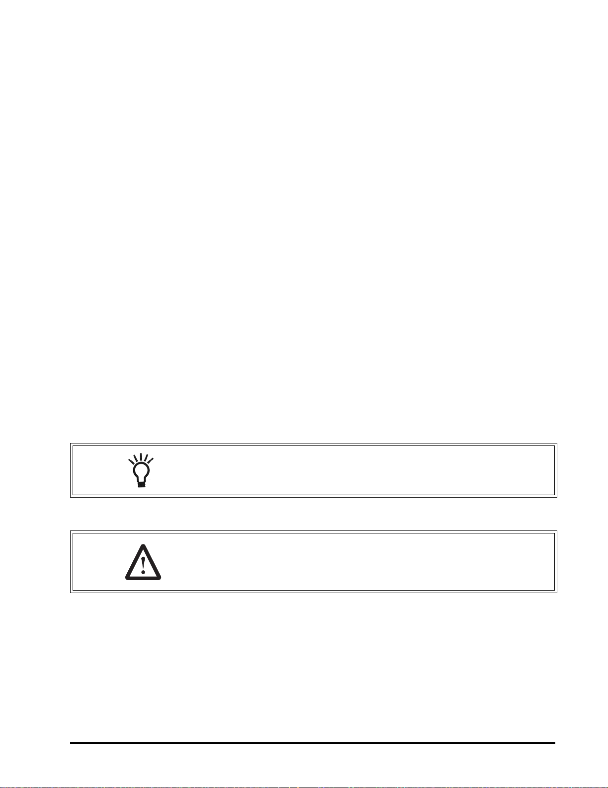
LOCATION OF SYSTEM
The reverse osmosis system is designed for installation under a sink,
usually in the kitchen or bathroom. The RO assembly can be placed on
the cabinet floor in any position that does not apply pressure on the
disconnect elbows. The RO product water faucet installs on the sink or
on the countertop next to the sink.
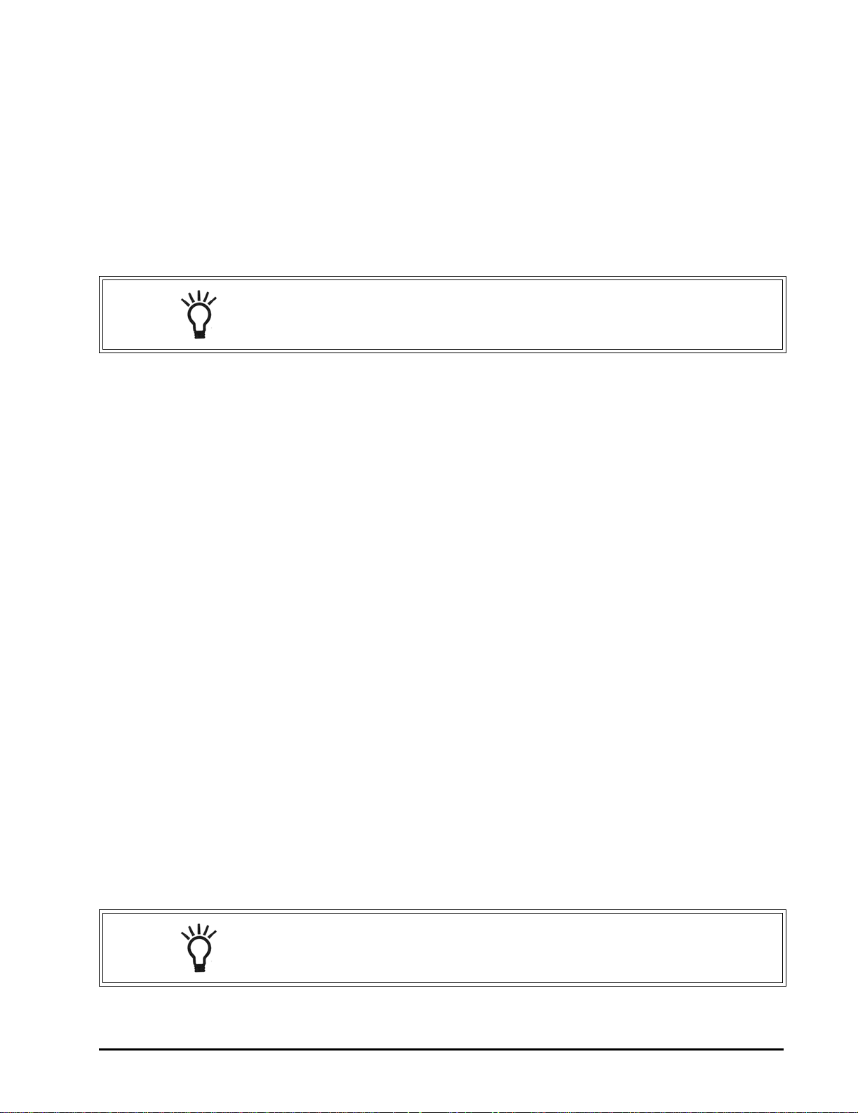
The RO system can also be located in a location away from the faucet.
A nearby water source and drain point are required.
NOTE: Keep the lengths of tubing short. Longer lengths of tubing
will decrease system performance. A booster pump can be used on
the supply line.
Water Supply: To provide supply water to the RO system inlet, a feed
supply fitting is required or install pipe fittings as needed.
Drain Point: A suitable drain point is needed for reject water from the
RO system. A floor drain, laundry tub, standpipe, sump, etc. are all
acceptable. A sink p-trap drain adapter is included to install as an
optional drain point where codes permit.
All components and tubing should be located in an area which is not
exposed to freezing temperatures. Do not expose unit or tubing to
direct sunlight.
Dispensing Faucet: The faucet should be placed near the sink where
drinking water is normally obtained. Convenience of use (filling of
water pitchers and glasses) and an open area beneath the faucet
under the sink for attaching product and drain tubing are
considerations. A 2-inch diameter flat surface is required above and
below the installation site. The thickness of mounting surface should
not exceed 1-1/4 inches. Avoid any strengthening webbing on the
underside of the sink.
RO Manifold Assembly: The manifold can be installed on either the
right or left side of the under-sink area or cabinet. Installation in the
basement is also an option. One possible location is near the
laundry/utility sink where cold potable water and drain access are
close. The location chosen should allow adequate clearance and
accessibility for membrane element changes.
Feed Water Connection: The feed water valve should be located as
close to the manifold assembly as possible. USE A POTABLE COLD
WATER SUPPLY ONLY. Softened water is preferred as it will extend
the life of the RO membrane element.
NOTE: The feed water connection is not included in the package.
THE BASIC REVERSE OSMOSIS SYSTEM 5
Rev B
Page 6

Drain Connection - Depending on plumbing codes, the waste water
may need to go to drain through an anti-siphon air gap. A detachable
faucet air gap is included with the system. If discharging into the utility
sink or standpipe, an air gap of greater than 1.5 inches above the flood
rim must be provided.
Do not connect the system drain line to the dishwasher drain or near
the garbage disposal. Back pressure from these units may cause the
air gap to overflow.
NOTE: All plumbing should be done in accordance with state and
local plumbing codes.
Some codes may require installation by a licensed plumber; check
with the local plumbing authority prior to installation.
In restricted under-sink areas, it may be easier to install the faucet first.
Allow adequate tubing lengths for final system placement.
Figure 1 Typical Under-Sink Installation
6 THE BASIC REVERSE OSMOSIS SYSTEM
Rev B
Page 7
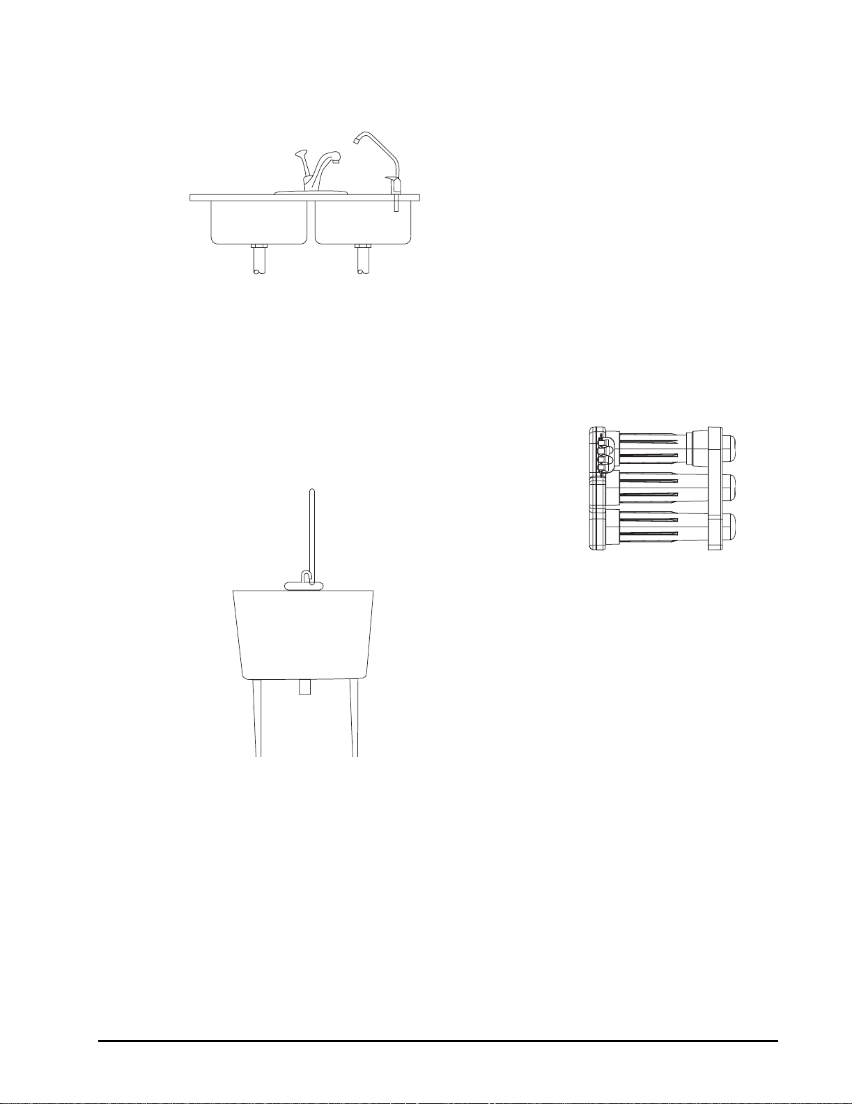
Figure 2 Typical Basement Installation
THE BASIC REVERSE OSMOSIS SYSTEM 7
Rev B
Page 8
REQUIRED TOOLS AND MATERIALS
• Adjustable wrench, and larger adjustable jaw pliers or pipe wrench
to fit sink drain
• Saw for cutting drain pipe
• Slotted and Phillips head screwdrivers
• Tubing cutters
• Electric drill and bits for cutting the faucet mounting hole
Note that some sinks will have a pre-drilled hole with a plug for the
faucet.
INSTALLATION
STEP 1: Install cold water supply valve
STEP 2: Install drain adapter
STEP 3: Install faucet
STEP 4: Make tubing connections
STEP 5: Install RO assembly
STEP 6: Put system into operation
NOTE: Consult a licensed plumber if you are not familiar with
plumbing procedures.
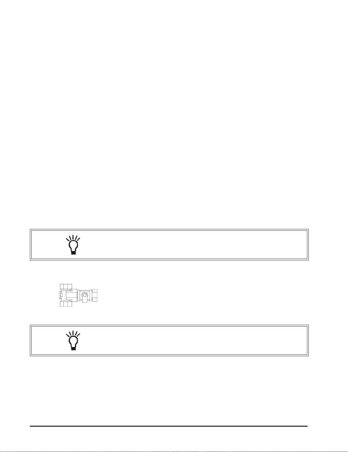
STEP 1: INSTALL COLD WATER SUPPLY VALVE
Comply with local plumbing codes. A typical connection using a water
supply valve is shown. The feed water valve is not included with
system. Contact supplier for this item.
Water Supply Valve
NOTE: Be sure to turn off the water supply and open a low faucet to
drain the pipe.
Cold water pipes vary in size and style. The installer will determine
type of valve that will be used. Install a valve on the cold water supply
pipe to adapt 1/2-inch OD tubing. If threaded fittings are used, be sure
to use pipe joint compound or Teflon tape on outside threads.
Turn the valve off.
8 THE BASIC REVERSE OSMOSIS SYSTEM
Rev B
Page 9
STEP 2: INSTALL DRAIN ADAPTER
Follow the instructions in the Appendix for installation of the Drain
Boa™.
The drain adapter is designed to fit 1-1/2-inch (3.8 cm) sink drain pipe.
The adapter installs directly to the sink tailpiece.
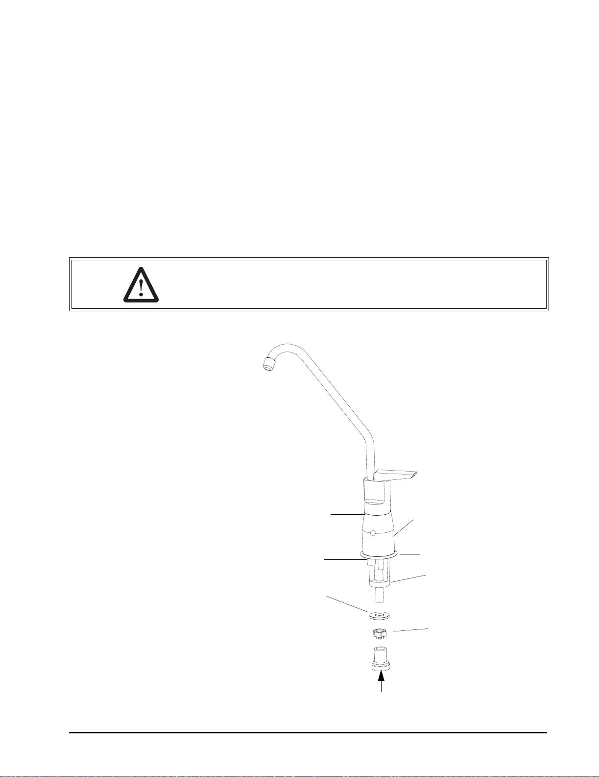
STEP 3: INSTALL FAUCET
A. Prepare Mounting Hole
1. Select a location for the faucet. Be sure it will fit flat against the sink
or counter and that there is space underneath for tubing.
2. If drilling is needed, make a 1-1/8-inch to 1-1/4-inch diameter hole.
WARNING: To avoid damaging a sink, consult a qualified plumber
or installer for the proper method of drilling holes in porcelain or
stainless steel.
Gasket
Horseshoe
Clip
Washer
Water In Connection
Air Gap Module
Trim Ring
Standoff
Nut
Figure 3
THE BASIC REVERSE OSMOSIS SYSTEM 9
Rev B
Page 10

B. Assemble Faucet
The tubing and fasteners are assembled to the faucet before the
faucet is placed in position. If not using the air gap module, skip to
step #3.
1. If the air gap feature is used, place the gasket in position on the
faucet.
2. Add the air gap module.
3. Slide the decorative ring over the tubing connections and up to the
bottom of the faucet.
4. Slide the standoff onto the threaded tube, followed by the standard
washer and nut.
5. Screw the threaded hose connector on the end of the threaded
tube.
6. Connect the blue 3/8-inch product tubing by firmly pushing it into
the connector.
7. If using the air gap module, push the black 3/8-inch tubing onto the
small hose barb from the collar. The red 1/2-inch tubing is pushed
onto the large hose barb.
8. Put the faucet into position.
9. The horseshoe clip is positioned around the threaded pipe under
the sink and above the standoff.
10. Tighten the nut against the clip to hold the faucet in position.
STEP 4: MAKE TUBING CONNECTIONS
The connections to the faucet should be complete, the remaining
connections are:
• Feed connection—clear tubing from feed valve to white elbow
connector
• Drain connection—either red tubing from the air gap or black
tubing from grey elbow connector will attach to the drain adapter
• Permeate connection—blue tubing from faucet to blue elbow
connection
• To the flush tank (if used)
• Attach the fittings to the manifold
A typical connection is shown in Figure 4.
10 THE BASIC REVERSE OSMOSIS SYSTEM
Rev B
Page 11

Collet Lock CLip
Tubing
Collet
O-Ring
O-Ring
NOTE: Make sure the tubing
is pushed past the O-rings
for a secure fit. Also, when
replacing any tubing, cut
tubing back ~1/4 inch prior
to re-inserting to prevent
leaks.
Figure 4 Side View and Cutaway of Tubing Fitting
NOTE: For optimal system performance, we recommend using
tubing lengths that are as short as possible.
Postfilter
Install the postfilter inline with the blue permeate tubing. Secure tubing
with collet lock clips.
Drain Adapter
The drain adapter has a rubber inlet that accepts the 3/8-inch black
drain tube or the 1/2-inch red tube. The 3/8-inch black tubing will
connect here if the faucet is not using the air gap module.
When the tubing is in position, use the supplied hose clamps to secure
the connection.
NOTE: When sliding tubing into the drain adapter inlet, wet the
tubing. Water will help the tubing slide into the rubber inlet.
THE BASIC REVERSE OSMOSIS SYSTEM 11
Rev B
Page 12

Feed Water Valve (Not Supplied)
The feed water valve attaches to a nearby cold water supply line. The
installer will determine the type and size of valve that will be installed.
This valve connects to the 1/2-inch natural tubing.
Flush Tank (Optional)
If the flush tank is used, the 1/4-inch blue tubing will be used to
connect to the top fitting of the RO assembly manifold. Remove the
plug and push the tubing into the fitting until it stops.
CAUTION: If the flush tank is not used, the 1/4-inch fitting on the
manifold must be plugged or water will leak out.
STEP 5: INSTALL RO ASSSEMBLY
The RO Assembly includes the following components: sumps (3),
support leg, prefilter, RO membrane elements (2), and postfilter. The
tubing is attached to the manifold by the elbow connectors. When
choosing a location for the system, allow enough tubing for it to be
moved for periodic servicing of the filters and membrane elements.
Figure 5 Merlin RO Assembly
12 THE BASIC REVERSE OSMOSIS SYSTEM
Rev B
Page 13

Locking Bar
First Position
Second Position
Recommended Placement Positions
The Merlin assembly should be positioned in one of two ways.
The first position is with the unit standing upright using the support leg
with the sumps horizontal. The tubing is directed to provide the best fit.
The second position, sets the unit on end so the manifold is horizontal
and the sumps are pointing up. The tubing is directed upward and the
locking bar is down to lock the tubing connections.
See illustrations at left.
The table below shows the coding system for the fitting connections.
Each fitting has a unique “keyed” socket on the manifold. Each fitting
also has a graphic symbol molded into the elbow with a corresponding
symbol on the manifold.
Connector Symbol Connection Tubing Color
O
Flushing (optional) Blue
C
U
WARNING: Be sure to lubricate the O-rings on the fitting elbows
prior to inserting into manifold.
WARNING: Do not turn the incoming water valve on until the
locking bar is in place.
Feed-Inlet Natural
Concentrate Black
Product Blue
NOTE: If the installation is not using the optional flush tank, the top
connection will not have tubing. Instead a plug will be inserted into
the fitting. Do not remove plug unless you are attaching the tubing
and the flush tank.
THE BASIC REVERSE OSMOSIS SYSTEM 13
Rev B
Page 14

When all of the connections have been made, use the locking bar to
hold the fittings in position. Match the symbols on the locking bar to the
corresponding symbols on the manifold.
Symbols
Figure 6 Locking Bar
STEP 6 SYSTEM STARTUP
1. Inspect all connections.
2. If the flush tank is not installed, the 1/4-inch port on the manifold
must be plugged.
3. Position manifold horizontal with openings facing up.
4. Remove new membrane elements from packaging.
CAUTION: Elements contain a foodgrade preservative. The use of
sterile/latex gloves is recommended.
5. Lubricate element O-rings, brine seals, and sump O-rings with
silicone lubricant.
6. Securely insert O-ring end of membrane elements into manifold.
7. Remove carbon/sediment prefilter from packaging. Check that
gaskets are in place.
8. Place carbon filter in manifold.
9. Replace sumps and hand-tighten.
Pressure Test System
To check for leaks, the system must be filled with water and brought up
to operating pressure.
1. Open cold water feed valve slowly. Run at 1/2 open for a minute,
then open fully.
2. Open faucet until water runs.
14 THE BASIC REVERSE OSMOSIS SYSTEM
Rev B
Page 15

3. Check for leaks.
NOTE: When the faucet is initially turned on, water may tempora rily
sputter from the air gap until the air is purged. Allow 1 to 3 hours for
any trapped air noise in the system to subside.
4. Purge the system. Open the faucet and run the water through the
RO system for one hour.
NOTE: The one hour flush removes a food grade preservative from
the membrane elements. It is not harmful but may affect the taste of
the water.
The RO system is now ready for use.
TO CARE FOR THE RO SYSTEM
The components of the RO system are designed to function with
minimal maintenance. However, the membrane elements and filters
will need to be replaced on a regular schedule.
Run the system for at least two minutes each day for optimal
performance.
REPLACEMENT OF PREFILTER AND POSTFILTER
The carbon/sediment prefilter removes sediment and certain
chemicals, such as chlorine, from the water. Depending on water use
and the amount of impurities, this filter should be replaced every six to
twelve months.
Whenever the prefilter is replaced, the postfilter should also be
replaced.
REPLACEMENT OF RO MEMBRANE ELEMENTS
The functional life of the RO membrane elements will vary based on
feed water quality. Product water should be tested periodically to verify
the membrane elements are performing properly. For most residential
applications, the RO membrane elements should be replaced every
two to four years.
NOTE: Softened water is recommended for optimal system
performance and RO membrane element life.
TO CARE FOR THE RO SYSTEM 15
Rev B
Page 16

REPLACEMENT OF THE PREFILTER, POSTFILTER, AND RO MEMBRANE ELEMENTS
1. Turn off the water supply to the RO System.
2. Reduce system water pressure by opening the faucet.
CAUTION: Even with the water supply turned off the membrane
and prefilter sumps will contain a considerable amount of water. By
positioning the RO assembly in a sink or tub, most of the water will
be contained.
3. Disconnect locking bar and place the fittings (with tubing still
connected) into a tub or bucket.
4. Move system into a contained area, such as a sink or tub.
5. Remove the support leg from the three sumps and unscrew the top
sump as shown to access the prefilter element. The support leg
functions as a wrench to loosen the sump, Figure 7.
Figure 7
NOTE: There is no need to disconnect tubing from fittings on the
manifold. Remove locking bar and pull fittings out. Lubricate O-rings
with silicone prior to re-assembly.
NOTE: If changing only the prefilter and postfilter, the other sumps
do not need to be removed.
If changing the membrane elements, the prefilter and postfilter
should also be changed.
16 REPLACEMENT OF THE PREFILTER, POSTFILTER, AND RO MEMBRANE ELEMENTS
Rev B
Page 17

6. Remove exhausted prefilter and discard.
CAUTION: The person handling the filters and membrane elements
must have clean hands to keep the system sanitized. The use of
sterile/latex gloves is recommended.
7. If Changing Membrane Elements:
A. Remove membrane sumps. Remove and discard used
elements.
B. Remove new elements from packaging.
CAUTION: Elements contain a foodgrade preservative. The use of
sterile/latex gloves is highly recommended.
C. Lubricate element O-rings, brine seals, and sump O-rings
with silicone lubricant.
D. Securely insert O-ring end of elements into manifold. See
Figure 8.
E. Replace sumps and hand-tighten.
NOTE: The system should be sanitized whenever a membrane
element or filter is replaced.
8. Sanitize the system.
A. The manifold should be positioned flat with the sump
connections facing up.
Prefilter Center Opening
Membrane Element Locations
Figure 8
REPLACEMENT OF THE PREFILTER, POSTFILTER, AND RO MEMBRANE ELEMENTS 17
Rev B
Page 18

B. Pour a tablespoon (15 milliliters) of chlorine bleach into the
center opening of the prefilter sump connection. See
Figure 8.
9. Install prefilter.
A. Remove new prefilter from packaging. Ensure gaskets are
secure. Insert prefilter into proper opening on manifold.
B. Lubricate sump O-ring with silicone lubricant.
C. With the prefilter element in place, screw the sump into the
connection. Do not overtighten.
NOTE: The sumps are sealed using an O-Ring. Tighten by hand. If
any leaks are detected when water pressure is applied, the sumps
can be tightened further.
10. Replace the postfilter.
A. To unlock the fittings from the tubing, push down on the collet
sleeves and pull the tubing out.
B. Discard the exhausted postfilter.
C. To prevent leaks, cut the tubing back approximately
1/4 inch prior to connecting the new postfilter. Make sure flow
direction arrow aligns with water path. Reinsert tubing and
collect locks.
11. Re-connect the fittings to the manifold and lock in position with
locking bar.
12. Re-position the assembly and turn the water supply on. Check the
system for any leaks.
CAUTION: When the faucet is opened, water may sputter from the
air gap until the trapped air is purged.
13. Open the faucet and run water for two minutes.
NOTE: Carbon fines may be present until the postfilter element is
flushed out.
14. Shut off the faucet and allow the system to stand idle for 20 to 30
minutes.
15. Open the faucet and run water for two minutes or until chlorine
odor is gone.
18 REPLACEMENT OF THE PREFILTER, POSTFILTER, AND RO MEMBRANE ELEMENTS
Rev B
Page 19

16. Check for any system leaks.
NOTE: If the two RO membrane elements were replaced the
system should be flushed for one hour. This flush removes the food
grade preservative from the elements. The preservative is not
harmful but may affect the taste of the water.
The RO system is now ready for use.
REPLACEMENT OF THE PREFILTER, POSTFILTER, AND RO MEMBRANE ELEMENTS 19
Rev B
Page 20

APPENDIX
20 APPENDIX
Rev B
Page 21

MERLIN COMPONENTS
OnDemand RO
MERLIN COMPONENTS 21
Rev B
Page 22

MERLIN PARTS LIST
Part Number Description
1255052 Complete Merlin system
1239705 Sump - interchangeable for all 3 positions
1244617 Manifold - complete
1239708 Support Leg
1240564 Drain Boa Kit
1240620 3/8-inch Black Tubing - 500 foot roll - John Guest Brand
1240621 3/8-inch Blue Tubing - 500 foot roll - John Guest Brand
1240622 1/2-inch Natural (clear) - 250 foot roll - John Guest Brand
1240623 1/2-inch Red Tubing - 250 foot roll - John Guest Brand
1240117 1/2-inch Feed Disconnect Elbow - White
1240118 3/8-inch Permeate Disconnect Elbow - Blue
1240116 3/8-inch Drain Disconnect Elbow - Dark Gray
1240119 1/4-inch Flush Disconnect Elbow - Light Blue
1239731 Locking Bar
1240326 Sump O-Ring
1254894 Airgap Faucet
1255693 Complete Fittings and Locking Bar Kit
1255736 Complete Tubing Install Kit
REPLACEABLE CARTRIDGES
Part Number Description
1238342 Membrane Element
1237460 Carbon Prefilter
1244746 Carbon Postfilter
Spare parts are available through your installing water treatment dealer.
22 MERLIN PARTS LIST
Rev B
Page 23

ACCESSORIES
Part Number Description
1261345 Merlin Flush Kit (Accumulator tank and 1/4-inch tubing)
1240619 1/4-inch Blue Tubing - 500 foot roll - John Guest Brand
1240632 Inlet Booster Pump, 110V/60Hz
1013501 Silicone Lubricant Pack
1240629 Feed Valve Tee - 1/2" x 1/2" x 1/2" OD Tubing - G.A. Murdock
USA
1240630 Feed Valve Tee - 5/8" x 5/8" x 1/2" OD Tubing - G.A. Murdock
USA
1262403 Feed Valve Tee - 5/8" x 5/8" x 1/2" OD Tubing -SeaTech
1262404 Feed Valve Tee - 14 mm x 14 mm x 1/2" OD Tubing -SeaTech
1262406 Feed Valve Tee - 15 mm x 15 mm x 1/2" OD Tubing -SeaTech
1262407 Feed Valve Tee - 3/8" x 3/8" threaded x 1/2" Tubing -SeaTech
1262408 Feed Valve Tee - 1/2" x 1/2" threaded x 1/2" Tubing -SeaTech
1262847 10-micron Sediment Prefilter
— Post Filter Mounting Clip Kit
NON-STOCKED INDIVIDUAL COMPONENTS
Part Number Description
1240626 Individual Collet Lock Clip- 1/4-inch Red - John Guest PN PIC1808R-X John Guest USA
1240627 Individual Collet Lock Clip- 3/8-inch White - John Guest PN PIC1812W-X John Guest USA
1240628 Individual Collet Lock Clip- 1/2-inch Blue - John Guest PN PIC1816B-X John Guest USA
1240624 1/4-inch JG Plug - John Guest PN P10808S John Guest USA
1240625 Faucet Connection Fitting - John Guest PN CI3212U7S John Guest USA
Spare parts are available through your installing water treatment dealer.
Recommended
Source
MERLIN PARTS LIST 23
Rev B
Page 24

DIMENSIONS
Performance Specifications1,
Permeate Flow Rate 0.33 gals/min (1.25 Lpm) 0.75 gals/min (2.84 Lpm) 0.50 gals/min (1.89 Lpm)
TDS Rejection (NaCl)
Minimum and Maximum Operating Conditions
Condition Minimum Maximum
Inlet Pressure 40 psi (2.76 bar) 80 psi (5.52 bar)
Inlet Temperature 40°F (4.44°C) 100°F (37.78°C)
Inlet TDS 50 mg/L 2,000 mg/L
Inlet Hardness 0 mg/L (0 grain) 171 mg/L (10 grain)
Inlet Chlorine 0 mg/L 1.0 mg/L
Inlet Iron 0 mg/L 0.1 mg/L
Inlet Manganese 0 mg/L 0.05 mg/L
Inlet pH 4 10
Inlet Turbidity 0 1 NTU
1. Based on 50 psi (3.44 bar), 77°F (25°C), 750 mg/L NaCl, 23.7% Recovery
2. System is designed for use on potable water systems only.
3. Specifications based on GE Osmonics testing data. For complete WQA test results to ANSI/NSF 58 standard,
see the Merlin Performance Data Sheet P/N 1263717.
3
2
Minimum Maximum Average
90% 99% 93%
24 DIMENSIONS
Rev B
Page 25

DIMENSIONS 25
Rev B
Page 26

SPECIFIC CONTAMINANT PERFORMANCE
Arsenic
Contaminant
a
Influent (avg.
mg/L)
0.049 0.00265 0.00612 94.6%
Effluent (ave.
mg/L)
Effluent (max.
mg/L)
Ave %
Reduction
Barium 11.1 0.189 1.9 98.3%
Cadmium 0.0307 0.0000704 0.0000704 99.8%
Chromium (VI) 0.353 0.00742 0.0147 97.9%
Chromium (III) 0.312 0.000624 0.00453 99.8%
Copper 3.22 0.0721 0.0721 97.8%
Fluoride 8.11 0.51 0.65 93.7%
Lead 0.159 0.000628 0.000628 99.6%
Nitrate/Nitrite (as N)
b
28.96 6.26 7.55 78.4%
Radium 226/228
Selenium 0.113 0.00249 0.003 97.8%
Total Dissolved Solids (TDS) 726 74.8 94.8 89.7%
a. This system has been tested for the treatment of water containing pentavalent arsenic (also known as As(V),
As(+5), or arsenate) at concentrations of 0.050 mg/L or less. This system reduces pentavalent arsenic, but
may not remove other forms of arsenic. This system is to be used on water supplies containing a detectable
free-chlorine residual at the system inlet or on water supplies that have been demonstrated to contain only
pentavalent arsenic. Treatment with chloramines (combined chlorine) is not sufficient to ensure complete
conversion of trivalent arsenic to pentavalent arsenic. Please see the Arsenic Facts section of the Merlin
system performance data sheet.
b. This system is acceptable for treatment of influent concentrations of no more than 27 mg/L nitrate and 3 mg/L
nitrite in combination measured as N and is certified for nitrate/nitrite reduction only for water supplies with a
pressure of 40 psi (2.76 bar) or greater.
To verify the level of nitrate/nitrite in the product water use the test strips that have been included with the
system. Follow the instrucions that are on the test strip packaging.
The level of nitrate/nitrite in the product water should be within local standards before placing the Merlin system
into operation.
Testing performed under standard laboratory conditions. Actual results may vary.
26 DIMENSIONS
Rev B
Page 27

SYSTEM PERFORMANCE RATING:
Product Water Production: 748 Gallons perday (2,831 Liters per day)
Average System Recovery: 23.70%
Average System Efficiency: 23.70%
Average System Recovery means the percentage of the influent water to the membrane portion of
the system that is available to the user as reverse osmosis treated water when operated as designed
(without a pressurized storage tank).
Average System Efficiency rating means the percentage of the influent water to the system that is
available to the user as reverse osmosis treated water under operating conditions that approximate
typical daily usage.
Efficiency rating is identical to recovery rating when the system is tested without a storage tank or
when a storage tank is bypassed.
SYSTEM SPECIFICATIONS AND OPERATING PARAMETERS
Minimum and Maximum Operating Conditions
Inlet Water Condition Minimum Maximum
Pressure 40 psi (2.76 bar) 80 psi (5.52 bar)
Temperature 40°F (4.44°C) 100°F (37.78°C)
TDS 50 mg/L 2,000 mg/L
Hardness 0 mg/L 171 mg/L
Chlorine 0.0 mg/L 1.0 m g/L
Iron 0.0 mg/L 0.1 m g/L
Manganese 0.0 mg/L 0.05 mg/L
PH 4.0 10.0
Actual system performance will vary depending on varying water temperature and pressure, TDS
levels and inlet water chemistry. Operating the system in water conditions outside the minimum or
maximum operating parameters may result in reduced system performance and membrane element
life.
System manufactured by:
GE Infrastructure
Water & Process Technologies
5720 N. Glen Park Road
Milwaukee, WI 53209-4454
U.S.A.
Direct spare parts and service inquiries to the system’s installing dealer.
DIMENSIONS 27
Rev B
Page 28

Contact your installing dealer for spare parts or service:
©Copyright 2004 General Electric Company
Printed in the USA P/N 1262366 Rev B
 Loading...