

Page 1
PANEL
CONNECTOR (RJ
-
45)
POWER
CONNECTORS (DB
-9)
NECTOR (TNC)
1 INTRODUCTION
The MDS SD transceiver (Figure 1) is a software-configurable,
industrial radio for use in wireless telemetry applications. Models
offered at the time of printing include: MDS SD2 (215-235 MHz),
SD4 (350-512 MHz), and SD9 (928-960 MHz). The term SD is
used for information common to all models of the radio.
The radio supports both polled and report-by-exception data networks, and interfaces with a variety of data control equipment
such as remote terminal units (RTUs), programmable logic controllers (PLCs), flow computers, and similar devices. Data interface connections support both Ethernet and serial (RS-232/485)
protocols.
LED INDICATOR
DC INPUT
ETHERNET
MDS SD Series
Quick Start Guide
NOTE: Retrofit Kits are available to ease installation at former
MDS x710 digital and analog sites. Consult your factory representative for ordering details.
2.1 Installation Steps
In most cases, the steps given here are sufficient to install the
transceiver. Refer to the Technical Manual for additional details,
as required.
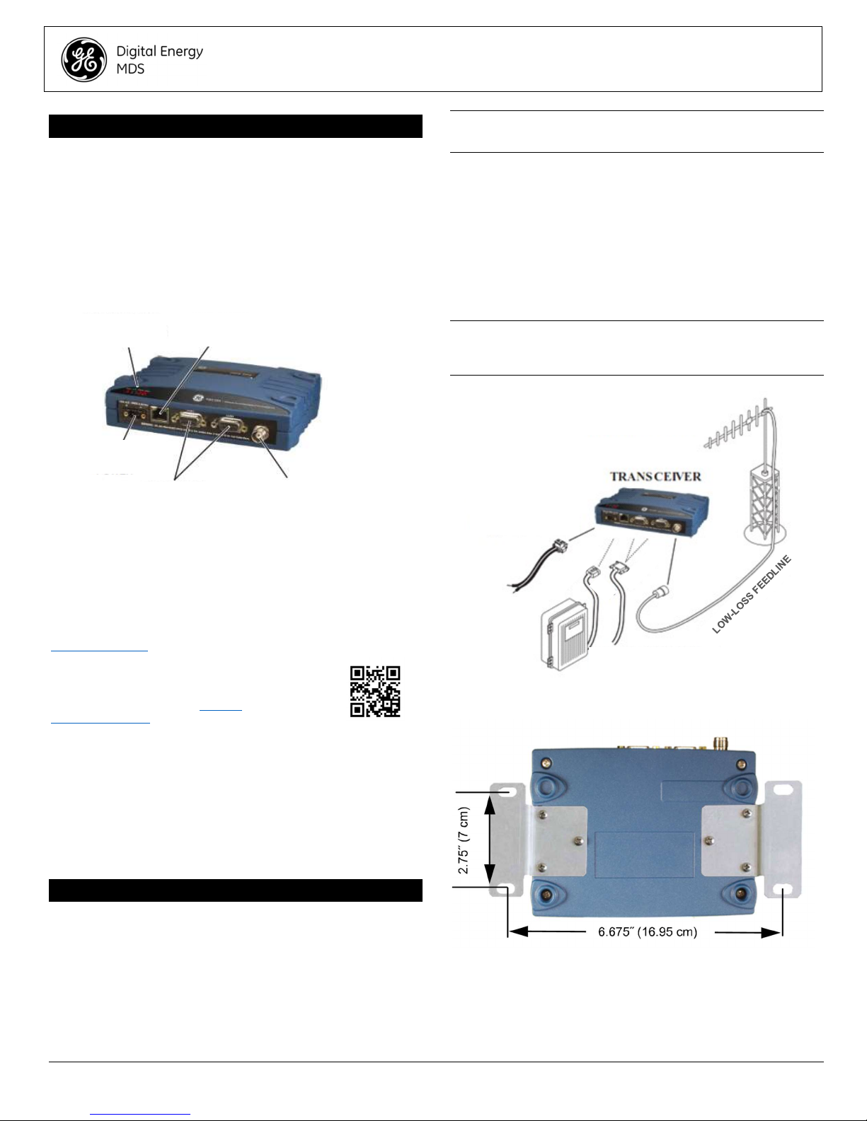
1. Mount the transceiver. Attach the supplied brackets to the
bottom of the transceiver case (if not already attached), using
the four 6-32 x 1/4 inch (6 mm) screws. Mounting bracket
dimensions are shown in Figure 3. If DIN Rail mounting
brackets are to be used, consult the Technical Manual for
instructions.
NOTE: To prevent moisture from entering the radio, do not mount
the case with the cable connectors pointing up. Also, dress all cables to prevent moisture from running along the cables and into
the radio.
ANTENNA SYSTEM
ANTENNA SYSTEM
Master Stations typically use
Master Stations typically use
omni-directional antenna
omni-directional antenna
SERIAL DATA
ANTENNA CON-
Figure 1. MDS SD Data Transceiver
1.1 Additional Information
This Setup Guide covers the essential installation and startup for
all SD transceivers except those operating in x710 mode. Alternate information is available in English, (see 05-4846A01 Technical Manual). GE MDS manuals, Setup guides, Firmware, drivers and Application Notes are available free of charge at
www.gemds.com.
GE MDS has produced a series of instructional
videos for configuration and setup of the Orbit
products on YouTube. These are available in
English, free of charge at: http://ti-
nyurl.com/pey2ull
1.1.1 x710 Mode—Different Manuals Required
The radio may be configured to emulate a corresponding MDS
x710 transceiver. For x710 mode information, consult these manuals instead:
Setup Guide (05-4669A01)
Technical Manual (05-4670A01)
2 INSTALLATION
There are three main requirements for installing the transceiver:
Adequate and stable primary power
An efficient and properly installed antenna system
Correct interface connections between the transceiver and the
data equipment.
Figure 2 shows a typical installation of the radio.
POWER SUPPLY
POWER SUPPLY
10.5-30 VDC @ 2.5A
10.5-30 VDC @ 2.5A
Negative Ground Only
Negative Ground Only
ETHERNET
ETHERNET
OR SERIAL
OR SERIAL
DATA TELEMETRY DEVICE
DATA TELEMETRY DEVICE
OR HOST COMPUTER
OR HOST COMPUTER
Figure 2. Typical Installation (Remote Site Shown)
Figure 3. Mounting Bracket Dimensions
2. Install the antenna and feedline. The antenna must be de-
signed to operate in the radio’s frequency band, and be
mounted in a location providing a clear path to associated station(s). At Remote sites, aim directional antennas toward the
Master Station. Low loss coaxial feedline should be used and
it should be kept as short as possible.
05-4847A01-GB, Rev. B MDS SD Series Setup Guide 1
Page 2

3. Connect the data equipment. Connection may be made us-
Transceiver
Session
ing Ethernet signaling, Serial protocols (RS-232/RS-485), or
both.
If Ethernet is to be used, connect your data equipment to the
front panel Ethernet port next to the PWR connector.
If serial is to be used, connect your data equipment to the
COM1 or COM2 port on the front panel. (Typically, COM2 is
used for connecting data equipment and COM1 is used for
serial management of the radio. Other assignments are possible. (Refer to the Technical Manual for details.) In all
cases, the radio is hardwired as a DCE device. A straightthru cable may be used in most applications.
NOTE: Do not connect the Ethernet port to a LAN with high traffic
levels. Excessive traffic will overload the port and Ethernet communications will be temporarily disabled.
4. Connect primary power. Input power must be 10.0 to 30
Vdc and capable of providing at least 2.5 Amperes. A power
connector with screw-terminals is provided (see Figure 4).
Strip the wire leads to 6 mm (1/4 inch) and insert them into
the wire ports. Be sure to observe proper polarity as shown
below. Tighten the binding screws securely.
NOTE: Some early models supported 10.5 to 16 Vdc power, not
10.0 to 30 Vdc. Always check the labeling above the Power con-
nector to verify the proper range for your unit.
Lead
Lead
Binding
Binding
Screws (2)
Screws (2)
factory shipped radio is 192.168.1.1. The default subnet
mask is 255.255.255.0.
3. Enter the radio’s IP address in a web browser window, just as
you would enter a website address. When the login screen
appears (Figure 6), enter the User Name and Password for
the radio. The default entries for a new radio are both admin.
Click OK.
Figure 6. Login Screen
4. The Basic Setup Wizard (Figure 7) begins automatically upon
connection to a new factory shipped radio. It displays a series
of screens with key selections as follows:
TX/RX Frequencies (entries must match station license)
RF Power Output
Operating Mode
Modem Type
Serial Port Configuration
Ethernet Bridging
Encryption Setting
AP or Remote Service
Continue through each wizard screen until all selections have
been made. (You may back up to previous screens if required, to
review or change settings.) Contact your network administrator if
you are unsure about a setting.
Retaining
Retaining
Screws (2)
Wire Ports (2)
Wire Ports (2)
(Polarity: Left +, Right -)
(Polarity: Left +, Right -)
Figure 4. DC Power Connector
CAUTION: The unit is designed for use with negative-ground
systems only. The power supply should be equipped with overload protection (NEC Class 2 rating), to protect against a short
circuit between its output terminals and the radio’s power connector.
Screws (2)
2.1.1 Configuration Settings
PC Running Terminal
Figure 5. Setup for PC Configuration
The SD Radio contains a Setup Wizard for fast, easy configuration of key settings. On a new radio shipped from the factory, the
wizard starts as soon as you are connected to the radio. Follow
the steps below to connect and use the wizard.
1. Connect an Ethernet cable (straight-thru or crossover)
between the radio and a PC as shown in Figure 5.
2. Configure your PC network settings to an IP address on the
same subnet as the radio. The default IP address on a new
Figure 7. Basic Setup Wizard
5. At the conclusion of the wizard, click Done. Configuration is
now complete for this radio. Run Remote Management Wizard, if required, for other installed radios in the network.
A summary of all SD settings (Figure 8) may be viewed, by
clicking Overview. The Overview screen may be formatted
for printing, by clicking Printer friendly configuration (at the
bottom of the screen.
6. When finished, log out of the Device Manager by clicking
Logout in the upper right hand side of the screen.
05-4847A01-GB, Rev. B MDS SD Series Setup Guide 2
Page 3

LED Name
Description
2.2.2 Antenna SWR Check
The antenna system’s standing wave ratio (SWR) should be
checked on new installations using a wattmeter suited to the frequency of operation. High SWR (above 2:1) may indicate an antenna or feedline problem.
2.2.3 RSSI Check (for Remotes)
Using the Maintenance & Status>>Performance screen, check
the received signal strength indication (RSSI). The radio must be
receiving a signal from the associated Master Station (LINK LED
on or blinking). In general, signal levels stronger than –80 dBm
will provide reliable communication and allow for a degree of
“fade margin.”
Optimize the RSSI at Remotes by slowly adjusting the direction
of the station antenna. Watch the RSSI indication for several seconds after making each adjustment, so that the RSSI accurately
reflects the new heading. With RSSI readings, the less negative
the number, the stronger the incoming signal.
Figure 8. Overview Summary Screen
NOTE: The radio may also be programmed using serial or Telnet
management methods. Refer to the Technical Manual for details.
2.2 Initial Checkout
In-service operation of the transceiver is completely automatic.
The only operator actions required are to apply DC power and
observe the LEDS for proper indications. Table 1 summarizes the
radio’s LED functions.
2.2.1 LED Functions
NOTE: LED labeling may vary on early units. LED position and
functionality remains as described below.
Figure 9. LED Status Indicators
Table 1: Description of LED Status Indicators
PWR POWER:
LAN ETHERNET:
DATA 1/2
LINK LINK: When lit, indicates that a communication link
NOTE: In addition to the LEDs above, the Ethernet connector
also has two embedded LEDs. A flashing green indicates Ethernet data activity. A yellow indicates 100 Mbps operation.
• Continuous—Power applied, no problems
detected.
• Rapid flash (5 times-per-second)—Alarm
indication.
• Flashing—Ethernet data activity is detected.
• Off—Ethernet signals not detected, or excessive
traffic is present.
DATA1 / DATA2: The DATA LEDs show data
activity on the DB-9 serial payload port(s).
exists with the another station.
NOTE: The radio’s RSSI facility limits the maximum displayed
signal strength to -60 dBm. A receive signal attenuator is available in the Configuration>>Radio>>Advanced Settings screen.
3 Troubleshooting
All radios in the network must meet the basic requirements listed
below for proper operation. Check these items first when troubleshooting a system problem:
Adequate and stable primary power
Secure connections (RF, data and power)
A clear transmission path between Master and each Remote
An efficient and properly aligned antenna system providing ad-
equate received signal strength.
Proper programming of radio settings
The correct interface between the transceiver and the con-
nected data equipment (correct cable wiring, proper data for-
mat, timing, etc.)
3.1 LEDs
The radio’s LED indicator panel provides useful information when
troubleshooting a system problem. Refer to Table 1 for LED indications.
3.2 Event Codes
When an alarm condition exists, the transceiver creates a message readable on the Maintenance & Status Screen. From this
screen, select Event Log to view the current alarm(s). Consult
the Technical Manual for details.
3.2.1 Types of Alarms
Minor Alarms—These alarms report conditions that, under most
circumstances will not prevent transceiver operation. This includes out-of-tolerance conditions, baud rate mismatches, etc.
The cause should be investigated and corrected to prevent system failure.
Major Alarms—These alarms report serious conditions that generally indicate a hardware failure, or other abnormal condition
that will prevent (or seriously hamper) further operation of the
transceiver. Major alarms may require factory repair. Contact
your factory representative for assistance.
3.3 Built-In Spectrum Analyzer/Graph
A Spectrum Analyzer/Graph is available to display other radio
signals near the SD radio’s operating frequencies. This can be a
helpful tool in cases of interference. The graph may be accessed
from the Maintenance & Status>>Radio Test screen.
05-4847A01-GB, Rev. B MDS SD Series Setup Guide 3
Page 4

To use the graph, simply enter the frequency you wish to use as
Antenna Gain
Safety
Distance
SD4
SD9
other
models:
Table 2:
COM1/COM2 Pin Descriptions
—RS-
232
Pin In/
DCD (Data Carrier Detect/Link)
RXD (Received Data)
TXD (Transmitted Data)
Sleep Mode Input
Signal Ground
—
Alarm Output
(DSR)
—
NOTE:
the center point of the graph, and enter the frequency range you
wish to cover. Select Show Spectrum to display the results.
The display creates a received signal strength indication (in dBm)
vs. frequency plot for signals near the center frequency (see Fig-
ure 10).
Invisible place holder
Figure 10. Spectrum Analyzer/Graph (Portion of Display)
4 COM1/COM2 REFERENCE
The COM1/COM2 connectors (Table 2) are typically used to connect an external DTE telemetry device to the radio, supporting
the RS-232 or RS-485 (balanced) format, depending on how the
radio is configured. The radio supports data rates of 300, 1200,
2400, 4800, 9600, 19200, 38400, 57600, and 115200 bps (asynchronous data only) on these connectors.
These connectors mate with a standard DB-9 plug available from
many electronics parts distributors.
Figure 11. COM1/COM2 Connector
(DB-9F) As viewed from outside the
radio
4.1 Pin Descriptions—RS-232 Mode
COM1/COM2 Pin Descriptions—RS-232 Table 2 provides pin
descriptions for the connector when operating in RS-232 mode.
For RS-422/485, refer to the Technical Manual.
Out Pin Description
1 OUT
2 OUT
3 IN
4 IN
5 --
6 OUT
7 IN Reserved.
8 OUT Reserved.
9 -- User I/O for special applications; not normally
pin indicates signal received.
—This pin supplies received
data to the connected device.
data from the connected device.
—Grounding this pin turns off
most circuits in a remote radio. This allows for
greatly reduced power consumption, yet preserves
the radio’s ability to be quickly brought on line.
This pin connects to ground
(negative supply potential) on chassis.
An RS-232 high/space
(+5.0 Vdc) on this pin indicates an alarm condition.
An RS-232 low/mark (–5.0 Vdc) indicates normal
operation. This pin may be used as an alarm
output.
used.
The radio is hard-wired as a DCE device.
—A low on this
—This pin accepts TX
5 REGULATORY AND PRODUCT IN-
FORMATION
RF Exposure Notice
Concentrated energy from a directional antenna may
pose a health hazard to humans. Do not allow people
to come closer to the antenna than the distances
listed in the table below when the transmitter is operating. More information on RF exposure can be found
online at the following website:
www.fcc.gov/oet/info/documents/bulletins.
Antenna Gain vs. Minimum RF Safety Distance
0–5 dBi 5–10 dBi 10–16.5 dBi
0.79 meter 1.41 meters 3.05 meters
0.46 meter .82 meters 1.74 meters
For SD1, maintain an RF safety distance of 1.80
SD1
SD2
meters for a 7 dBd (9.15 dBi) antenna. Use of higher
gain antennas means increasing the distance
accordingly.
For SD2, maintain an RF safety distance of 1.50
meters for a 7 dBd (9.15 dBi) antenna. Use of higher
gain antennas means increasing the distance
accordingly.
Consult factory prior to operation.
05-4847A01-GB, Rev. B MDS SD Series Setup Guide 4
Page 5

FCC Part 15 Notice
Operation is subject to the following two conditions: (1) this device may
not cause harmful interference, and (2) this device must accept any interference received, including interference that may cause undesired operation. Any unauthorized modification or changes to this device without the
express approval of the manufacturer may void the user’s authority to operate this device. Furthermore, this device is intended to be used only
when installed in accordance with the instructions outlined in this manual.
Failure to comply with these instructions may void the user’s authority to
operate this device.
Industry Canada Notice
This Class A digital apparatus complies with Canadian ICES-003.
Modifications:
Any modifications made to this device that are not approved by GE MDS
LLC, Inc. may void the authority granted to the user to operate this equipment.
Servicing Precautions
When servicing energized equipment, be sure to wear appropriate Personal Protective Equipment (PPE). During internal service, situations
could arise where objects accidentally contact or short circuit components
and the appropriate PPE would alleviate or decrease the severity of potential injury. When servicing radios, all workplace regulations and other
applicable standards for live electrical work should be followed to ensure
personal safety.
Manual Revision and Accuracy
This manual was prepared to cover a specific version of firmware code.
Accordingly, some screens and features may differ from the actual unit
you are working with. While every reasonable effort has been made to
ensure the accuracy of this publication, product improvements may also
result in minor differences between the manual and the product shipped
to you. If you have additional questions or need an exact specification for
a product, please contact GE MDS using the information at the back of
this guide. In addition, manual updates can be found on our web site at
www.gemds.com
Environmental Information
The manufacture of this equipment has required the extraction and use of natural resources. Improper disposal
may contaminate the environment and present a health
risk due to hazardous substances contained within. To
avoid dissemination of these substances into our environ-
encourage you to use the appropriate recycling systems for disposal.
These systems will reuse or recycle most of the materials found in this
equipment in a sound way. Please contact GE MDS or your supplier for
more information on the proper disposal of this equipment.
Battery Disposal —This product may contain a battery. Batteries must
be disposed of properly, and may not be disposed of as unsorted municipal waste in the European Union. See the product documentation for specific battery information. Batteries are marked with a symbol, which may
include lettering to indicate cadmium (Cd), lead (Pb), or mercury (Hg). For
proper recycling return the battery to your supplier or to a designated collection point. For more information see: www.weeerohsinfo.com.
ment, and to limit the demand on natural resources, we
Product Test Data Sheets
Test Data Sheets showing the original factory test results for this unit are
available upon request from the GE MDS Quality Leader. Contact the
factory using the information at the back of this manual. Serial numbers
must be provided for each product where a Test Data Sheet is required.
CSA/us Notice
This product is approved for use in Class 1, Division 2, Groups A, B,
C & D Hazardous Locations. Such locations are defined in Article 500 of
the National Fire Protection Association (NFPA) publication NFPA 70,
otherwise known as the National Electrical Code. The transceiver has
been recognized for use in these hazardous locations by the Canadian
Standards Association (CSA) which also issues the US mark of approval
(CSA/US). The CSA Certification is in accordance with CSA STD C22.2
No. 213-M1987.
CSA Conditions of Approval: The transceiver is not acceptable as a
stand-alone unit for use in the hazardous locations described above. It
must either be mounted within another piece of equipment which is certified for hazardous locations, or installed within guidelines, or conditions of
approval, as set forth by the approving agencies. These conditions of approval are as follows: The transceiver must be mounted within a separate
enclosure which is suitable for the intended application. The antenna feed
line, DC power cable and interface cable must be routed through conduit
in accordance with the National Electrical Code. Installation, operation
and maintenance of the transceiver should be in accordance with the
transceiver's installation manual, and the National Electrical Code. Tampering or replacement with non-factory components may adversely affect
the safe use of the transceiver in hazardous locations, and may void the
approval. A power connector with screw-type retaining screws as supplied by GE MDS must be used.
CE Mark and Radio Equipment Directive (RED) Notice (applies
to select bands of SD04 product only)
Product that is CE marked is compliant with European Union Radio
Equipment Directive 2014/53/EU.
GEMDS products employ a variety of wireless technologies and frequencies. These can include, cellular M2M, WIFI, and licensed narrowband radio frequencies. The user is responsible to ensure that proper spectrum
licenses are obtained for all licensed uses, carrier SIMs are authorized for
M2M cellular, and proper antenna gain is used to maintain local regulatory compliance.
Hazardous Locations Notice
WARNING
EXPLOSION HAZARD!
Do not disconnect equipment unless power has
been switched off or the area is known to be nonhazardous. Refer to Articles 500 through 502 of the
National Electrical Code (NFPA 70) for further information on hazardous locations and approved Division 2 wiring methods.
NO USER SERVICEABLE PARTS INSIDE
1.
05-4847A01-GB, Rev. B MDS SD Series Setup Guide 5
 Loading...