

Page 1
RCL220_manual_v3-draft.doc
05-XXXXA01 Version 3 Draft Page 1 of 79 9/20/2016
GE MDS RCL220 Manual
P/N 05-XXXXA01
Version 3
Page 2

RCL220_manual_v3-draft.doc
05-XXXXA01 Version 3 Draft Page 2 of 79 9/20/2016
Table of Contents
1 Important Information ............................................................................................................................................................ 4
1.1 Antenna Installation Warnings ................................................................................................................................. 4
1.2 ESD Notice ............................................................................................................................................................................ 4
1.3 FCC Approval Notice ....................................................................................................................................................... 4
1.4 FCC Part 15 Notice ........................................................................................................................................................... 4
2 Introduction .................................................................................................................................................................................. 5
2.1 Access Point ........................................................................................................................................................................ 7
2.1.1 USB Port Connector Pinout ................................................................................................................................ 9
2.1.2 DB-25 Connector Pinout ...................................................................................................................................... 9
2.1.3 Power Connector Pinout ..................................................................................................................................... 10
2.2 entraNET 220 OEM Radio Module ............................................................................................................................ 10
2.2.1 J1 (Ribbon Cable) Connector Pinout .............................................................................................................. 12
2.2.2 J4 (Board Mount) Connector Pinout .............................................................................................................. 13
2.2.3 RF Connector ............................................................................................................................................................. 13
2.3 entraNET 220 Packaged Radio Module ................................................................................................................ 14
2.3.1 DB-25 Connector Pinout ...................................................................................................................................... 15
2.3.2 RF Connector ............................................................................................................................................................. 16
2.3.3 Power Connector Pinout ..................................................................................................................................... 16
3 Packaged or OEM Radio Command Line ...................................................................................................................... 17
3.1 Common Setup Tasks .................................................................................................................................................... 17
3.1.1 Key the Transmitter for Test Purposes ......................................................................................................... 17
3.1.2 Upgrade firmware on Packaged Radio Module or OEM Radio Module (outside OCU) ....... 17
3.2 Packaged or OEM Radio Command Reference ................................................................................................ 30
3.2.1 ALARM ........................................................................................................................................................................... 30
3.2.2 AUTH .............................................................................................................................................................................. 30
3.2.3 COM1 ............................................................................................................................................................................. 32
3.2.4 COM2 ............................................................................................................................................................................. 33
3.2.5 CONFIG ......................................................................................................................................................................... 35
3.2.6 DEVICE ........................................................................................................................................................................... 35
3.2.7 ENCRYPT ....................................................................................................................................................................... 37
3.2.8 GPS .................................................................................................................................................................................. 37
3.2.9 HELP ............................................................................................................................................................................... 38
3.2.10 LOG ................................................................................................................................................................................. 38
3.2.11 LOGIN ............................................................................................................................................................................. 39
3.2.12 LOGOUT ........................................................................................................................................................................ 39
3.2.13 PASSWORD ................................................................................................................................................................. 39
3.2.14 PROGRAM .................................................................................................................................................................... 40
3.2.15 RADIO ............................................................................................................................................................................. 41
3.2.16 REBOOT ......................................................................................................................................................................... 44
3.2.17 REPEATERS .................................................................................................................................................................. 44
3.2.18 SLEEP ............................................................................................................................................................................. 45
3.2.19 STATS ............................................................................................................................................................................. 46
3.2.20 VER .................................................................................................................................................................................. 46
3.2.21 YARD ............................................................................................................................................................................... 48
4 Access Point Menu Interface ............................................................................................................................................... 50
4.1 Login Screen ........................................................................................................................................................................ 50
4.2 Starting Information Screen ....................................................................................................................................... 51
4.3 Main Menu ............................................................................................................................................................................ 51
4.3.1 Network Configuration Menu ........................................................................................................................... 53
4.3.2 System Configuration Menu .............................................................................................................................. 54
4.3.3 Security Configuration Menu ............................................................................................................................ 60
4.3.4 Statistics / Logging Menu ................................................................................................................................... 61
Page 3

RCL220_manual_v3-draft.doc
05-XXXXA01 Version 3 Draft Page 3 of 79 9/20/2016
4.3.5 LCU AP Statistics / Logging Menus ............................................................................................................... 66
4.3.6 Repeater AP Statistics / Logging Menus .................................................................................................... 68
4.3.7 Device Information Menu ................................................................................................................................... 70
4.3.8 Maintenance / Tools Menu ................................................................................................................................. 72
5 Troubleshooting .......................................................................................................................................................................... 77
6 Change Log ................................................................................................................................................................................... 79
Page 4

RCL220_manual_v3-draft.doc
05-XXXXA01 Version 3 Draft Page 4 of 79 9/20/2016
1 Important Information
1.1 Antenna Installation Warnings
1. All antenna installation and servicing is to be performed by qualified technical personnel only.
When servicing the antenna, or working at distances closer than those listed below, ensure
the transmitter has been disabled.
2. Depending upon the application and the gain of the antenna, the total composite power could
exceed 15 watts EIRP average vs. time. For fixed/mobile configuration, the distances in the
table below must be followed.
Antenna Gain vs. Minimum Safety Distance
(Based upon a 4.26% Duty Cycle, 0 dB Feedline Loss)
Uncontrolled Environment Exposure limits
Fixed/Mobile Antenna Gain
0-6 dBi
6-10 dBi
10-16.5 dBi
Minimum RF Safety Distance
0.4 meters
0.7 meters
1.6 meters
1.2 ESD Notice
To prevent malfunction or damage to this product, which may be caused by Electrostatic Discharge
(ESD), the radio should be properly grounded at the time of installation. In addition, the installer or
maintainer should follow proper ESD precautions, such as touching a bare metal object to dissipate
body charge, prior to touching components or connecting/disconnecting cables.
1.3 FCC Approval Notice
This device is offered as a licensed transmitter per FCC Parts 80, 90 and 95. It is approved for use
under the following conditions: Changes or modifications not expressly approved by the party
responsible for compliance will void the user’s authority to operate the equipment.
Installation, operation and maintenance of the transceiver should be in accordance with the
transceiver's installation manual and applicable local, regional, and national electric codes. Tampering
or replacement with non-factory components may adversely affect the safe use of the transceiver and
may void the approvals.
1.4 FCC Part 15 Notice
This equipment has been tested and found to comply with the limits for a Class A digital device,
pursuant to Part 15 of the FCC Rules.
Operation is subject to the following two conditions: (1) this device may not cause interference, and (2)
this device must accept any interference, including interference that may cause undesired operation
of the device. Changes or modifications not expressly approved by the party responsible for
compliance could void the user's authority to operate the equipment.
Page 5
RCL220_manual_v3-draft.doc
05-XXXXA01 Version 3 Draft Page 5 of 79 9/20/2016
2 Introduction
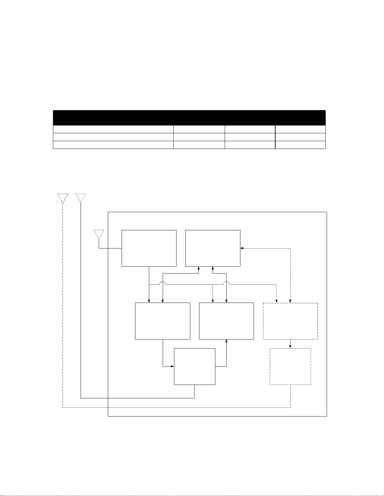
This document provides details of the entraNET 220 System. The entraNET 220 System supports
Repeaters, OCUs, and LCUs. Repeaters employ an Access Point and three Packaged Radio Modules.
Each OCU employs an OEM Radio Module while each LCU employs one Access Point and one
Packaged Radio Module.
MDS Radio Unit
Used for OCU
Used for LCU
Used for
Repeater
entraNET 220 OEM Radio Module
1 0 0
entraNET 220 Packaged Radio Module
0 1 3
Access Point
0 1 1
Note that additional information vital to Phase V operation is given in SHL-028, The MDS entraNET 220
Phase V Primer.
Block diagrams for each unit are shown in the following figures.
Mounting Plate
eNET 220 AP
eNET 220
Packaged Radio
Module (PRM)
Transmitter
eNET 220 Packaged
Radio Module
(PRM)
Receiver 1
eNET 220 Packaged
Radio Module
(PRM)
Receiver 2
GPS Timing Receiver
Duplexer
TX Notch Filter
or Duplexer
1 PPS
COM2
DTE
COM3
DCE
COM1
COM2
DCE
COM2
DCE
COM2
DCE
Figure 1 entraNET 220 Repeater Block Diagram
Page 6
RCL220_manual_v3-draft.doc
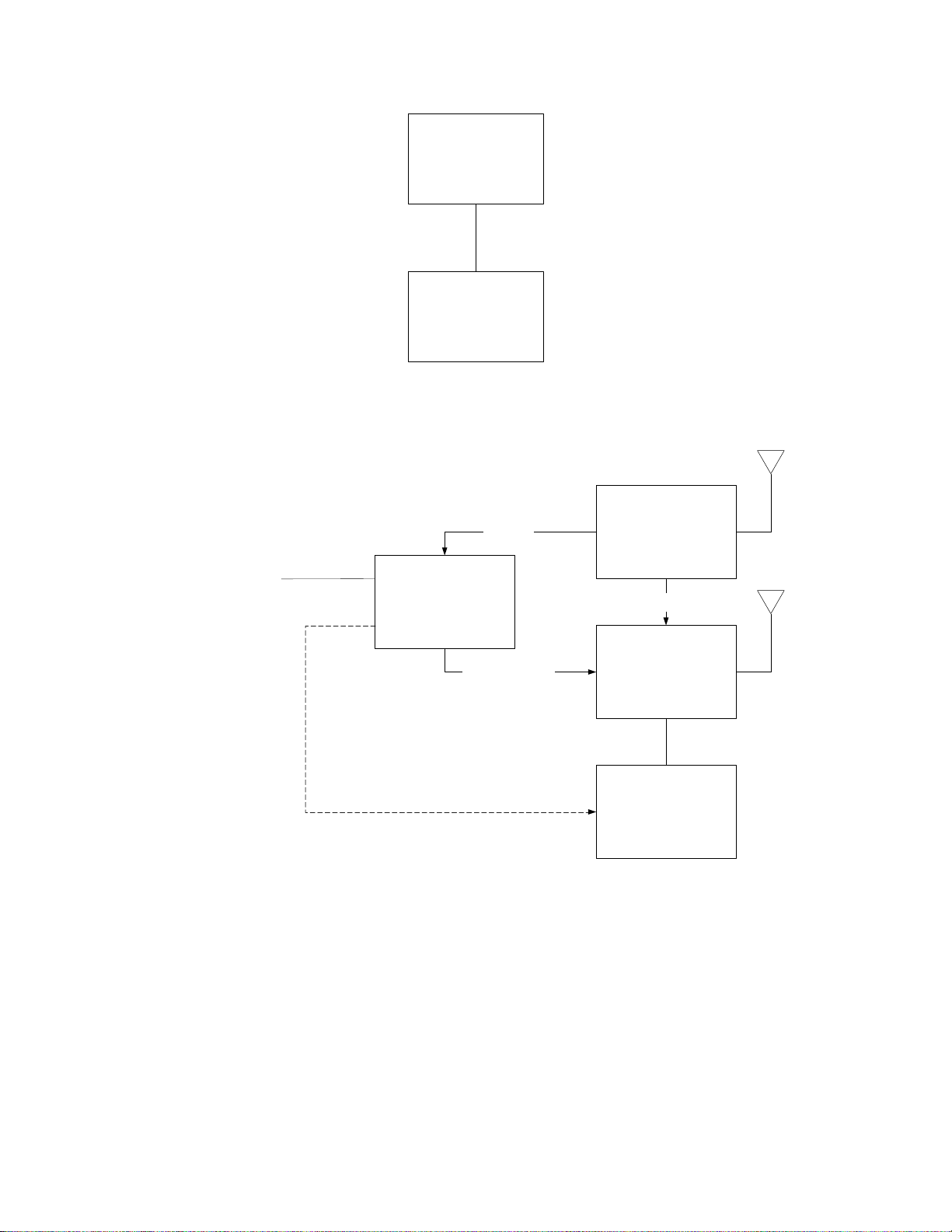
05-XXXXA01 Version 3 Draft Page 6 of 79 9/20/2016
entraNET 220
OEM
Radio Module
(ORM)
RCL Vendor OCU
Controller
COM2
Figure 2 entraNET 220 OCU Unit Block Diagram
eNET 220
Packaged
Radio Module
(PRM)
GPS Timing Receiver
1 PPS
Position
RCL Vendor LCU
Controller
COM2 (RS-232 or
422)
COM1
eNET 220 AP
Position / Diag
COM1
COM2
LAN
COM3
Figure 3 entraNET 220 LCU Unit Block Diagram
Page 7
RCL220_manual_v3-draft.doc
05-XXXXA01 Version 3 Draft Page 7 of 79 9/20/2016
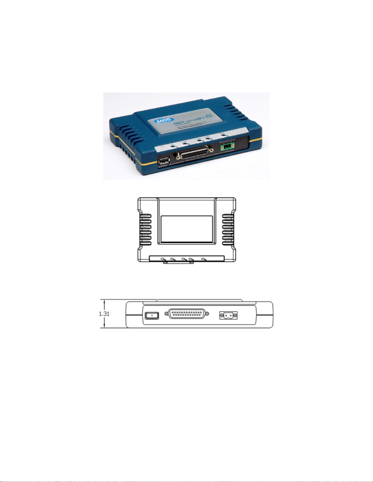
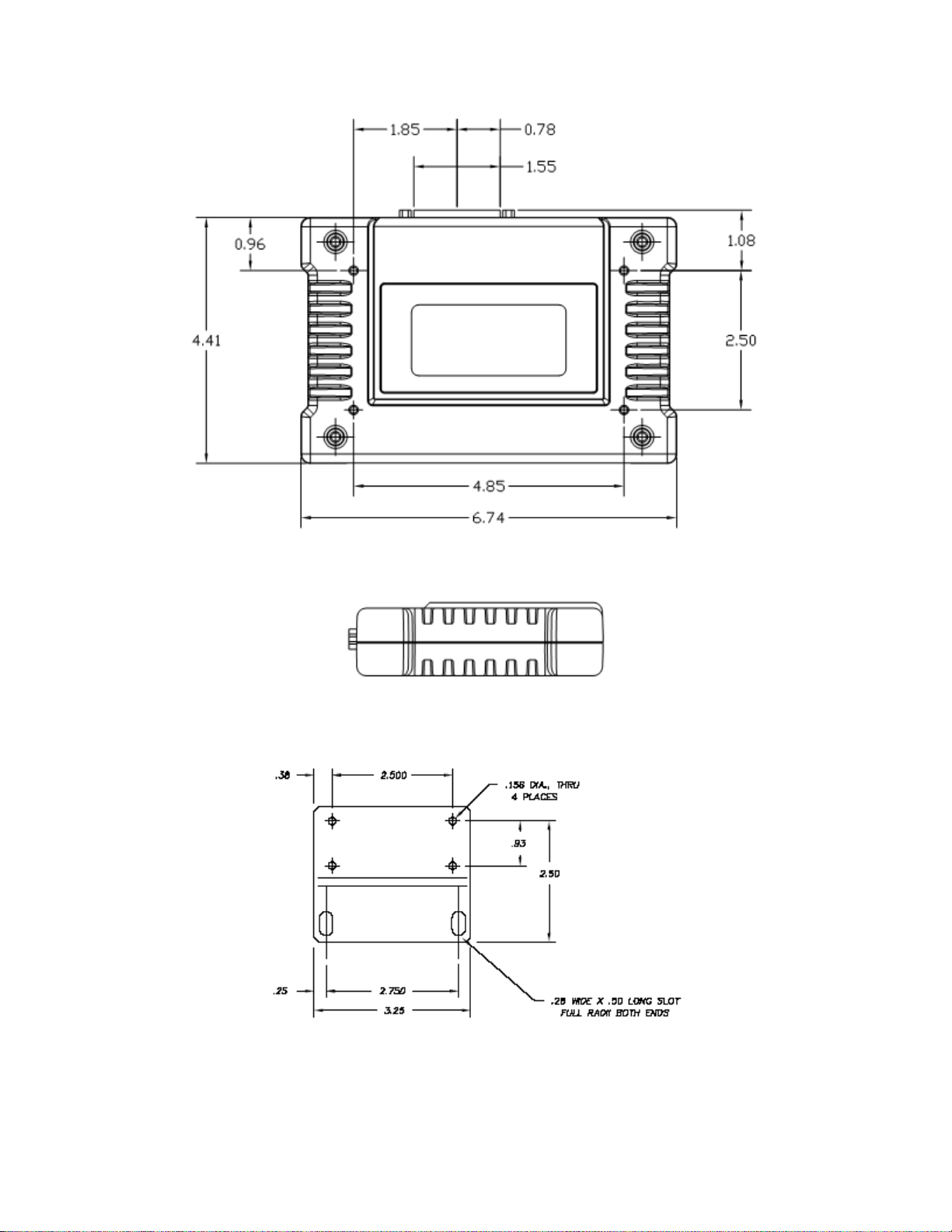
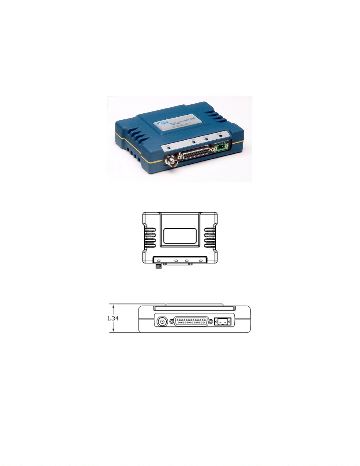
2.1 Access Point
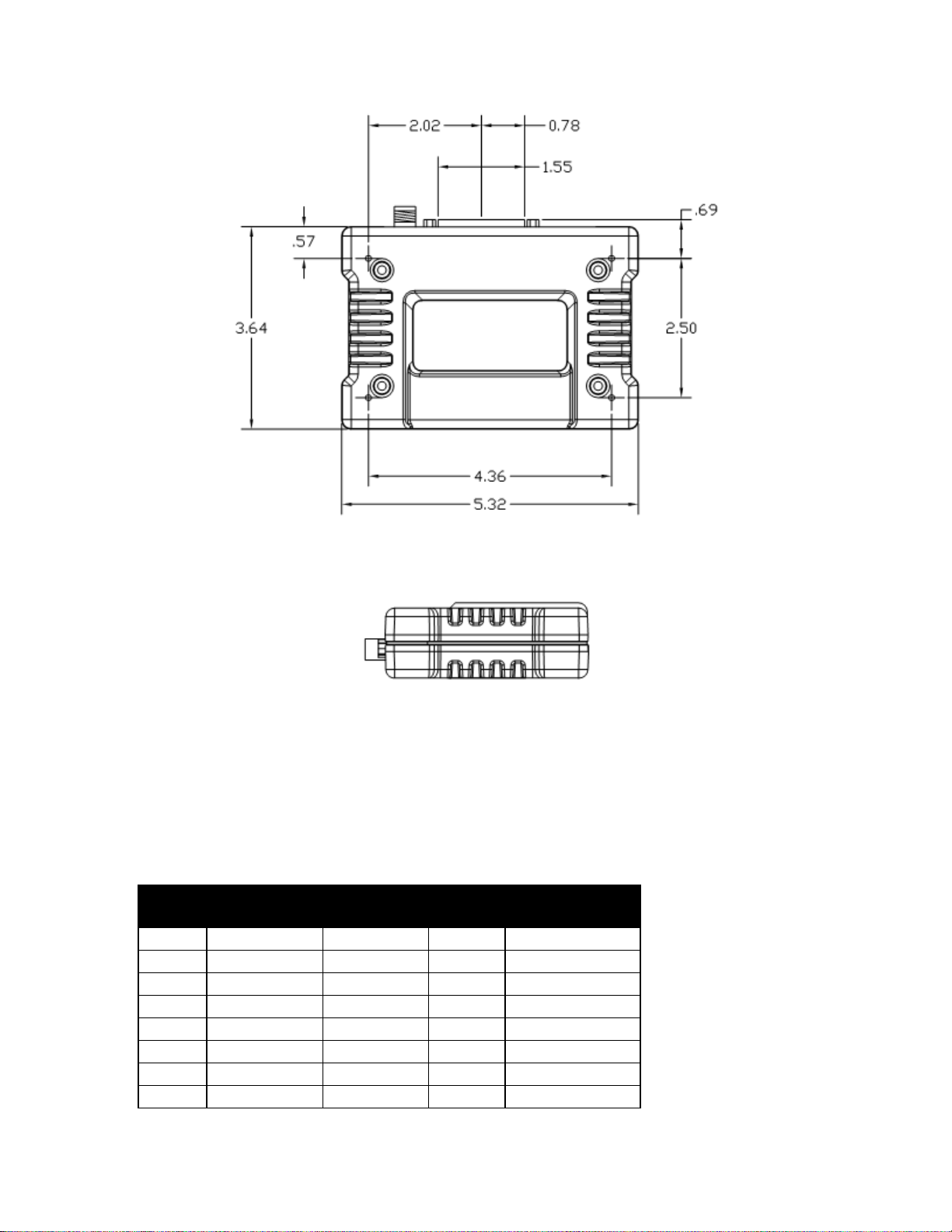
This unit is used in the repeater and must also fit within the enclosure used at the LCU. Photos and
mechanical dimensions of this unit appear below.
Figure 4 Access Point
Figure 5 Access Point (Top View)
Figure 6 Access Point (Front View)
Page 8
RCL220_manual_v3-draft.doc
05-XXXXA01 Version 3 Draft Page 8 of 79 9/20/2016
Figure 7 Access Point (Bottom View)
Figure 8 Access Point (Side View)
Figure 9 Mounting Bracket (Can be used with Access Point or Packaged Radio Module)
Page 9

RCL220_manual_v3-draft.doc
05-XXXXA01 Version 3 Draft Page 9 of 79 9/20/2016
2.1.1 USB Port Connector Pinout
The Access Point provides a USB Port conforming to version 1.1 of the USB standard. The pinout for
this connector is given in the table below.
Pin
Signal Name
Description
1
PC_USB_+5V
+5 VDC
2
USBD-
USB Data Minus
3
USBD+
USB Data Plus
4
GROUND
Ground
2.1.2 DB-25 Connector Pinout
The table below provides the pinout information for the final AP version employing a DB-25 connector.
Please see “TD_RCL_Adapter_Board_Instruction_Sheet2.pdf” for information on our 03-4758A03
breakout kit for the Access Point and Packaged Radio Module.
DB-25
Pin
Signal
Direction WRT MDS
Equipment
1
COM3_DCD
Input
2
COM2_TXD
Input
3
COM2_RXD
Output
4
COM2_RTS
Input
5
COM2_CTS
Output
6
COM3_TXD
Output
7
GND
Input/Output
8
COM2_DCD
Output
9
COM3_CTS
Input
10
COM3_RTS
Output
11
COM3_DTR
Output
12
COM3_RXD
Input
13
GND
Input/Output
14
ETH_TX_H
Output
15
ETH_TX_L
Output
16
ETH_RX_H
Input
17
ETH_RX_L
Input
18
EXT_KEY
Output
19
EXT_DET
Input
20
COM2_DTR
Input
21
ALARM_OUT
Output
22
GPS_PPS_L
Input
23
GPS_PPS_H
Input
24
COM1_RXD
Input
25
COM1_TXD
Output
The DB-25 connector is female, and the orientation of the connector as looking into the front panel of
the unit is as shown below.
Page 10
RCL220_manual_v3-draft.doc
05-XXXXA01 Version 3 Draft Page 10 of 79 9/20/2016
12 11 10 9 8 7 6 5 4 3 2 1
24 23 22 21 20 19 18 17 16 15 14
13
25
2.1.3 Power Connector Pinout
The Access Point provides a Phoenix 17 76 69 2 connector for DC power in. A surge protection device
such as a Polyphaser IS-17VDC-30A-NG capable of limiting the voltage input to the radio to less than
30 Volts should be employed.
Pin
Signal Name
Direction with respect to MDS Equipment
Description
1 (L)
PWR
Input
10 to 30 VDC input,
125 mA at 13.8 VDC
2 I
GROUND
Input
Power return.
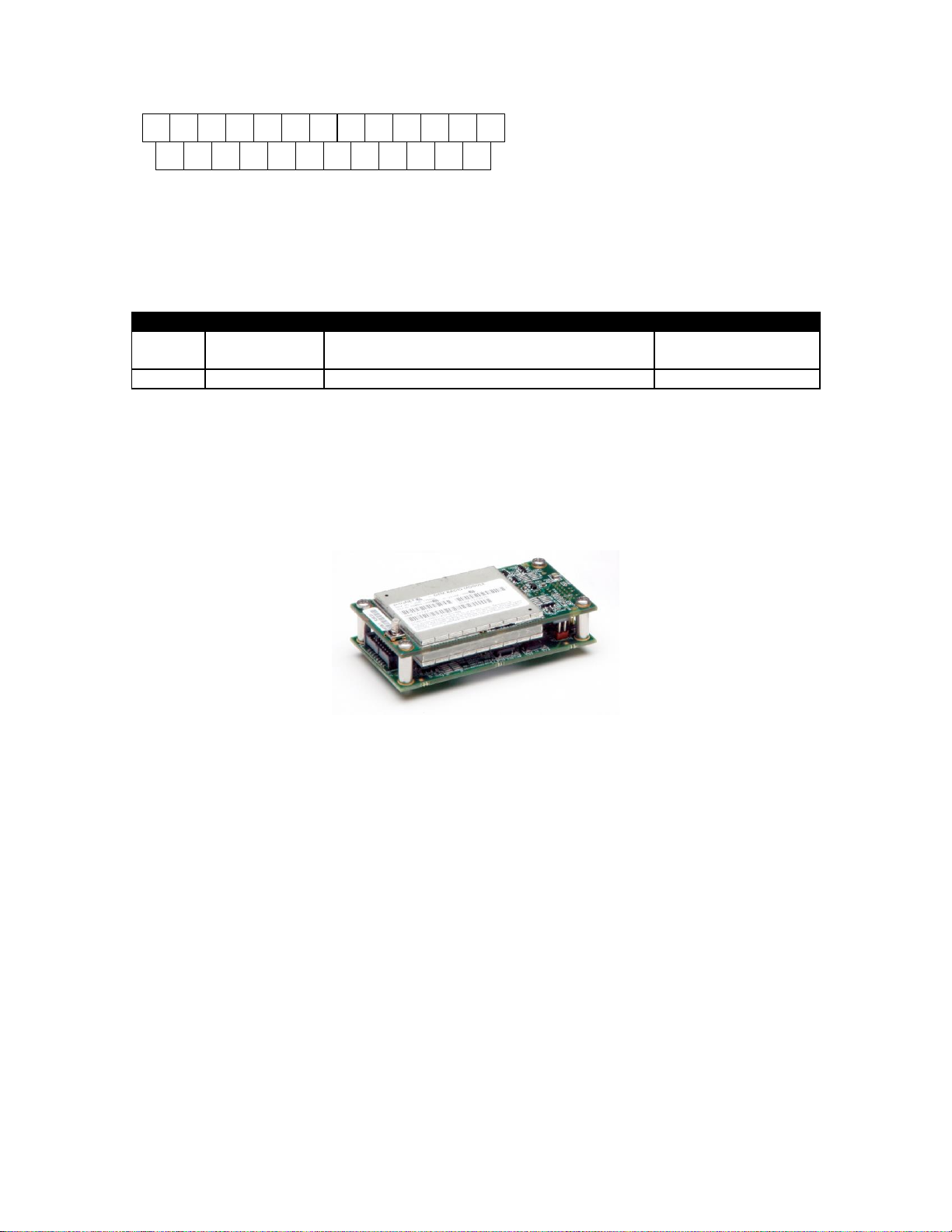
2.2 entraNET 220 OEM Radio Module
This unit is used in each OCU. It is a two-board solution (as shown below) that mates with RCL vendor
OCU hardware. Mechanical diagrams are provided below as well. The interfaces used by OEM Radio
Modules are listed in the tables below.
Figure 10 entraNET 220 OEM Radio Module (SMB Connector Not Shown)
Page 11
RCL220_manual_v3-draft.doc
05-XXXXA01 Version 3 Draft Page 11 of 79 9/20/2016
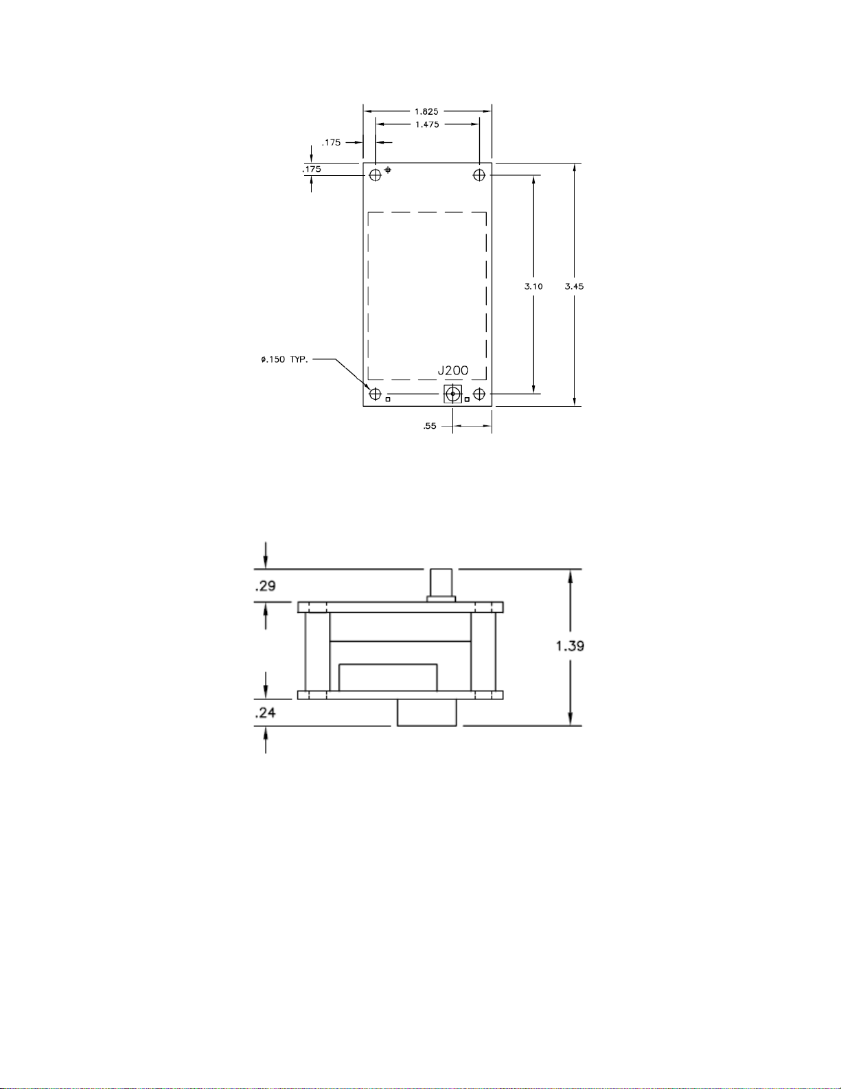
Figure 11 entraNET 220 OEM Radio Module (Top/Shield View)
Figure 12 entraNET 220 OEM Radio Module (End View)
Page 12
RCL220_manual_v3-draft.doc
05-XXXXA01 Version 3 Draft Page 12 of 79 9/20/2016
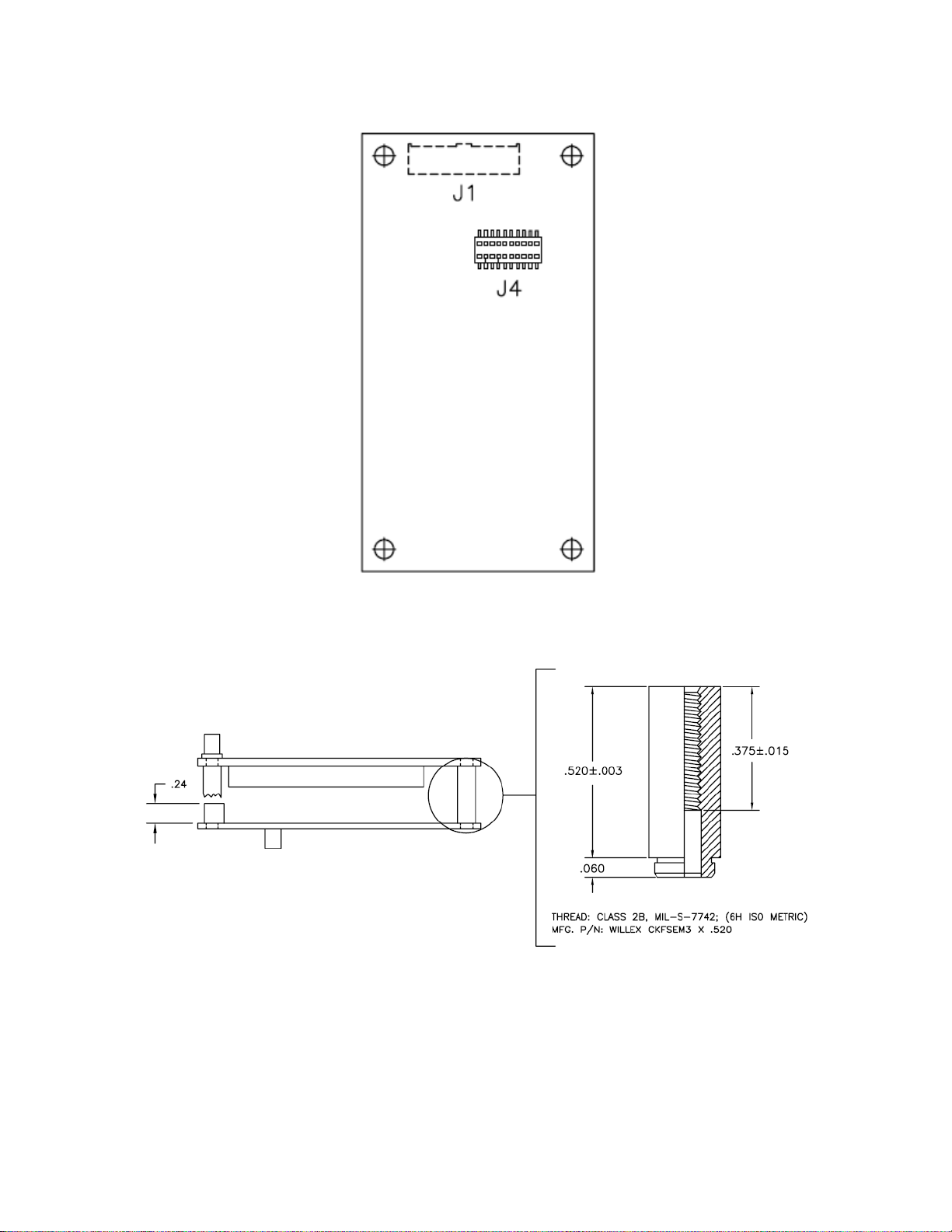
Figure 13 entraNET 220 OEM Radio Module (Bottom View)
Figure 14 entraNET 220 OEM Radio Module (Side View with PEM detail)
2.2.1 J1 (Ribbon Cable) Connector Pinout
The J1 Connector is a Samtec STMM-108-02-T-D-SM-K-TR. The mating connector is a Samtec TCSD08-D-xx.xx-01-F-N. J1 is the main interface to the OEM Radio Module.
Page 13

RCL220_manual_v3-draft.doc
05-XXXXA01 Version 3 Draft Page 13 of 79 9/20/2016
Pin
Function
Direction WRT MDS Equipment
Notes
1
Not Connected
2
VIN
Input
6 – 12 VDC, 1 A Max.
3
TXD
Input
Serial Data Input, 0 to 5 V.
4
IO1
Output
Slot Timing Signal. 0 to 3.3 V.
5
RXD
Output
Serial Data Output, 0 to 3.3 V.
6
IO2
Output
Reserved. 0 to 3.3 V.
7
Do Not Connect
8
IO3
Input
ALARM_IN. 0 to 5 V.
9
Do Not Connect
10
Not Connected
11
Do Not Connect
Output
Reserved, -6 to +6 V.
12
Not Connected
13
Do Not Connect
Input
Reserved, -12 to +12 V.
14
Not Connected
15
GROUND
Input
Return for VIN and signals.
16
Not Connected
2.2.2 J4 (Board Mount) Connector Pinout
The J4 Connector is a SAMTEC RSM-110-02-L-D-TR. J4 is not typically populated on the OEM Radio
Module.
Pin
Function
Direction WRT MDS Equipment
Notes
1
Not Connected
2
Not Connected
3
Not Connected
4
Not Connected
5
IO3
Input
ALARM_IN. Active Low. 0 to 5 V.
6
Not Connected
7
Not Connected
8
Not Connected
9
GROUND
Input
Return for VIN and signals.
10
TXD
Input
Serial Data Input. 0 to 5 V.
11
GROUND
Input
Return for VIN and signals.
12
IO2
Output
Reserved. 0 to 3.3 V.
13
IO1
Output
Slot Timing Signal. 0 to 3.3 V.
14
Not Connected
15
Not Connected
16
RXD
Output
Serial Data Output, 0 to 3.3 V.
17
VIN
Input
6 – 12 VDC, 1 A Max.
18
Not Connected
19
VIN
Input
6 – 12 VDC, 1 A Max.
20
Not Connected
2.2.3 RF Connector
The RF Connector is a straight mount 50 Ohm SMB jack.
Page 14
RCL220_manual_v3-draft.doc
05-XXXXA01 Version 3 Draft Page 14 of 79 9/20/2016
2.3 entraNET 220 Packaged Radio Module
In the LCU, one entraNET 220 Packaged Radio Module is used. In the Repeater, three are used. Each
instance employs identical hardware so that only one configuration must be spared. The packaged
module is provided in a cast aluminum housing as shown. Mounting for this unit is shown below.
Mechanical dimensions are also given. The interfaces used by Packaged Radio Modules are listed in
the tables below.
Figure 15 entraNET 220 Packaged Radio Module
Figure 16 entraNET 220 Packaged Radio Module (Top View)
Figure 17 entraNET 220 Packaged Radio Module (Front View)
Page 15
RCL220_manual_v3-draft.doc
05-XXXXA01 Version 3 Draft Page 15 of 79 9/20/2016
Figure 18 entraNET 220 Packaged Radio Module (Bottom View)
Figure 19 entraNET 220 Packaged Radio Module (Side View)
2.3.1 DB-25 Connector Pinout
The following table describes the pinout for the DB-25 version of the PRM. Please see
“TD_RCL_Adapter_Board_Instruction_Sheet2.pdf” for information on our 03-4758A03 breakout kit for
the Access Point and Packaged Radio Module.
New DB25 Pin
Signal
Previous PRM
Connector
Previous
PRM Pin
Direction WRT MDS
Equipment
1
COM3_DCD
N/A
N/A
Input
2
COM2_TXD/TXD+
J3 (COM2)
6
Input
3
COM2_RXD/RXD+
J3 (COM2)
5
Output
4
COM2_RTS/TXD-
J3 (COM2)
8
Input
5
COM2_CTS
J3 (COM2)
7
Output
6
COM3_TXD
N/A
N/A
Output
7
GND
J3 (COM2)
4
Input/Output
8
COM2_DCD/RXD-
J3 (COM2)
2
Output
Page 16

RCL220_manual_v3-draft.doc
05-XXXXA01 Version 3 Draft Page 16 of 79 9/20/2016
New DB25 Pin
Signal
Previous PRM
Connector
Previous
PRM Pin
Direction WRT MDS
Equipment
9
COM3_CTS
N/A
N/A
Input
10
COM3_RTS
N/A
N/A
Output
11
COM3_DTR
N/A
N/A
Output
12
COM3_RXD
N/A
N/A
Input
13
GND
N/A
N/A
Input/Output
14
ETH_TX_H
N/A
N/A
Output
15
ETH_TX_L
N/A
N/A
Output
16
ETH_RX_H
N/A
N/A
Input
17
ETH_RX_L
N/A
N/A
Input
18
EXT_KEY
I/O 1 Output
19
EXT_DET
I/O 2 Input
20
COM2_DTR
J3 (COM2)
3
Input
21
ALARM_OUT
I/O 3 Output
22
GPS_PPS_L
I/O
5
Input
23
GPS_PPS_H
I/O
6
Input
24
TXD*
J5 (COM1)
5
Input
25
RXD**
J5 (COM1)
4
Output
* TXD is called COM1_RXD on the AP. It truly is an input to the MDS unit.
** RXD is called COM1_TXD on the AP. It truly is an output from the MDS unit.
The DB-25 connector is female, and the orientation of the connector as looking into the front panel of
the unit is as shown below.
12 11 10 9 8 7 6 5 4 3 2 1
24 23 22 21 20 19 18 17 16 15 14
13
25
2.3.2 RF Connector
The RF connector is TNC. Lightning suppression such as a Polyphaser IS-B50 series protector should
be employed between the antenna and the radio. The body of the protector should be well grounded
to earth ground. In addition, the shield of the feedline should be connected to earth ground before
entry into any inside enclosure.
2.3.3 Power Connector Pinout
The Packaged Radio Module provides a Phoenix 17 76 69 2 connector for DC power in. A surge
protection device such as a Polyphaser IS-17VDC-30A-NG capable of limiting the voltage input to the
radio to less than 30 Volts should be employed as near to the radio as possible.
Pin
Signal Name
Direction with respect to MDS Equipment
Description
1 (L)
PWR
Input
6 to 30 VDC input, 800
mA at 13.8 VDC
2 I
GROUND
Input
Power return.
Page 17

RCL220_manual_v3-draft.doc
05-XXXXA01 Version 3 Draft Page 17 of 79 9/20/2016
3 Packaged or OEM Radio Command Line
For accessing the COM2 console of the Packaged Radio Module or the OEM Radio Module, use a serial
terminal emulator program such as HyperTerminal, Putty, or ucon. The default settings are: baud rate
19200, no parity, 8 data bits, and 1 stop bit. The pins for this port are listed in section 2.3.1.
3.1 Common Setup Tasks
3.1.1 Key the Transmitter for Test Purposes
1. Log in to the radio on its COM2 console.
2. Put the radio into calibration mode by entering RADIO MODE=CAL.
3. Select the frequency for the test transmission, and enter with RADIO AUXTX=<frequency>.
4. Enter RADIO TXKEY=ON.
5. When finished, enter RADIO TXKEY=OFF.
The test transmission is modulated (not CW) and is a repetitive data pattern over the air.
3.1.2 Upgrade firmware on Packaged Radio Module or OEM Radio
Module (outside OCU)
1. Log in to the radio on its COM2 console.
2. Put the radio into calibration mode by entering RADIO MODE=CAL.
3. Set the radio to stay in calibration mode on reboot RADIO TXSTART=0.
4. Set the radio to default to console mode COM2 DEFAULT=CONSOLE.
5. Close the terminal program.
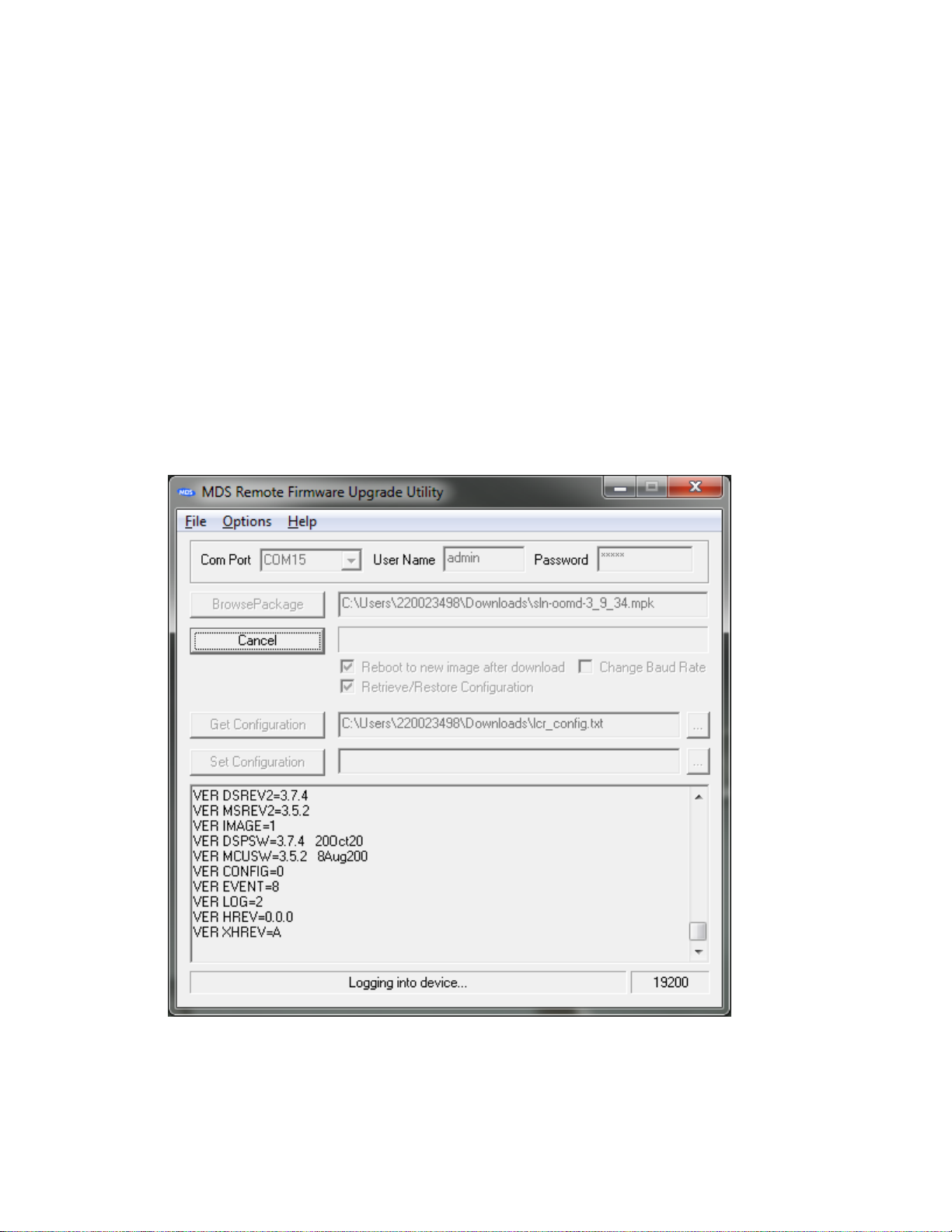
6. Start the Remote Upgrade Utility, version 4.2.0 or later.
7. The PRM and ORM have different firmware versions (as do the AP when used in a repeater vs.
onboard). Please be aware of the firmware version you are using and make sure it is
appropriate for the unit you are working with.
Page 18
RCL220_manual_v3-draft.doc
05-XXXXA01 Version 3 Draft Page 18 of 79 9/20/2016
8. In the Remote Upgrade Utility, select the PC COM port you are using to connect to the radio.
9. Set User Name to admin with the correct password (default admin).
10. Click Browse Package to locate the firmware file you will upgrade to.
11. Before clicking Upgrade Firmware, make sure “Reboot to new image after download” is
selected and “Change Baud Rate” is NOT selected (leaving baud rate at the current value has
proven more reliable).
12. If desired, select “Retrieve/Restore Configuration” to set the utility to query the radio’s current
configuration and restore it after the upgrade. This is needed when jumping several revisions
of the firmware since some parameter locations could have changed setting parameters to
their defaults upon upgrade.
13. Optionally, you may click “Get Configuration” to download the radio’s settings to a text file you
specify by clicking the “…” button on the same line.
14. Optionally, you may click “Set Configuration” to upload the radio’s settings from a text file
similarly.
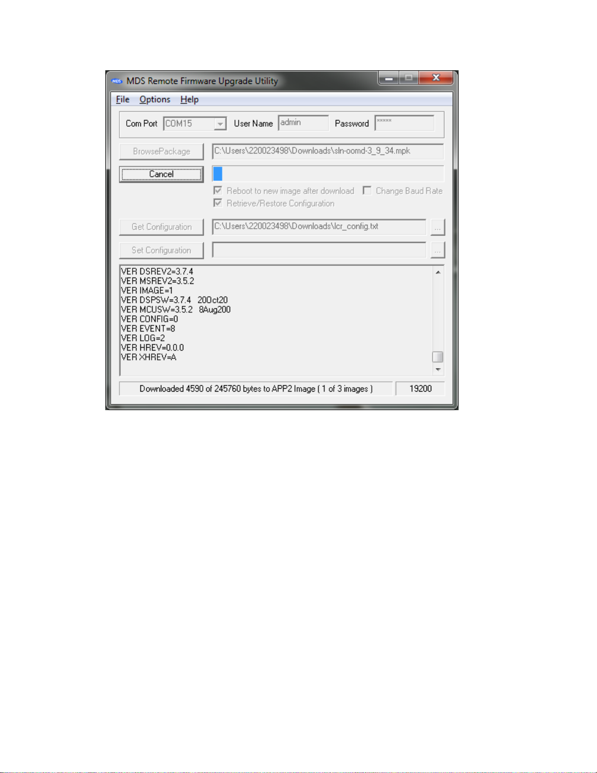
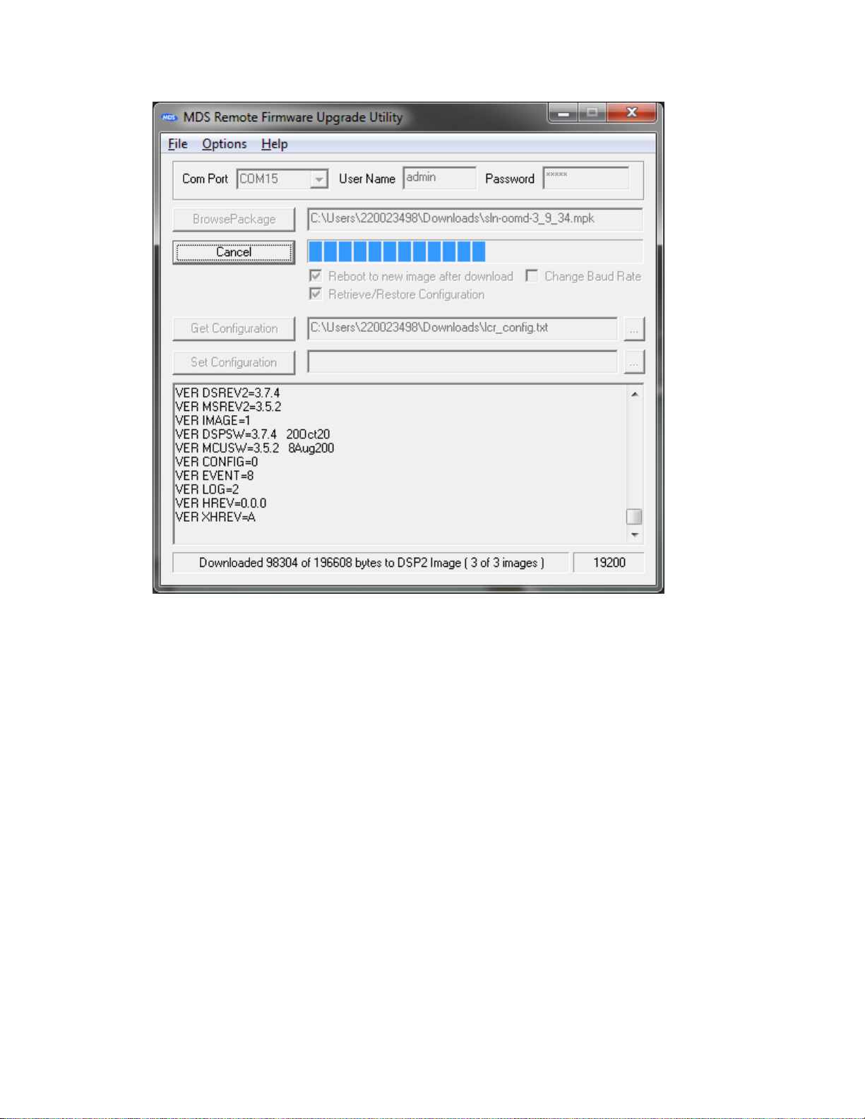
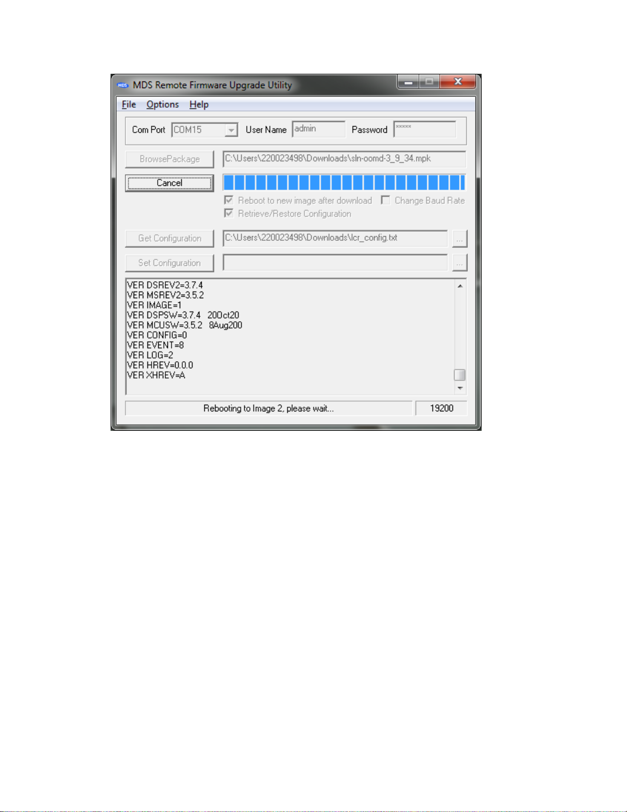
15. When ready to upgrade the firmware, click “Upgrade Firmware”.
The upgrade process goes through several steps, providing feedback in the bottom status bar as it
progresses. There are three major steps: Upgrading the application image, upgrading the MCU
image, and upgrading the DSP image. The whole process can take 5 to 10 minutes.
Page 19

RCL220_manual_v3-draft.doc
05-XXXXA01 Version 3 Draft Page 19 of 79 9/20/2016
Page 20
RCL220_manual_v3-draft.doc
05-XXXXA01 Version 3 Draft Page 20 of 79 9/20/2016
Page 21
RCL220_manual_v3-draft.doc
05-XXXXA01 Version 3 Draft Page 21 of 79 9/20/2016
Page 22
RCL220_manual_v3-draft.doc
05-XXXXA01 Version 3 Draft Page 22 of 79 9/20/2016
Page 23

RCL220_manual_v3-draft.doc
05-XXXXA01 Version 3 Draft Page 23 of 79 9/20/2016
Page 24
RCL220_manual_v3-draft.doc
05-XXXXA01 Version 3 Draft Page 24 of 79 9/20/2016
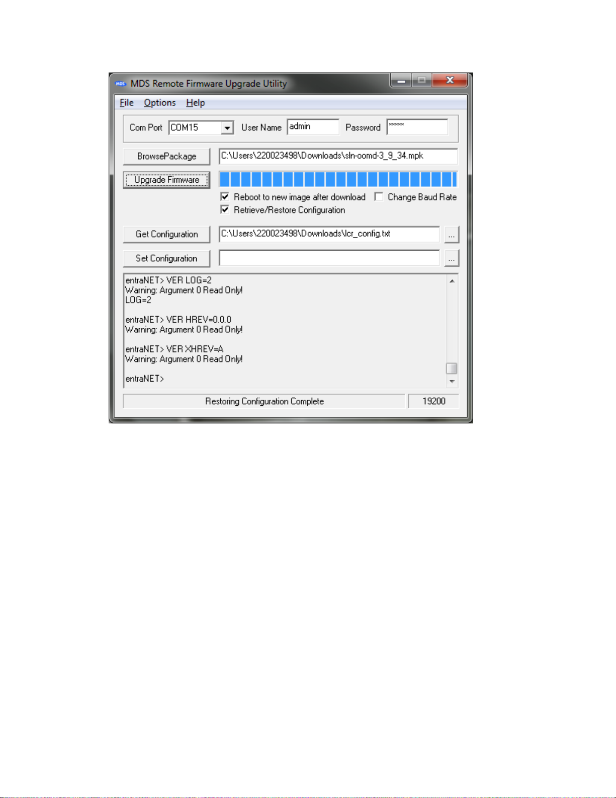
When restoring the configuration, several parameters will return “Warning: Argument 0 Read
Only!”. This is expected operation.
If for some reason the upgrade process fails, you can log into the radio to see the status using the
“VER” command. If the images you attempted to upgrade (APP, MCU, and DSP) are all filled in and
the currently running image is the one you upgraded, the upgrade succeeded. If an image is not
filled in, you will need to restart the upgrade process at step 1.
If the utility seems to hang when rebooting to the new firmware, you can attempt logging in via a
terminal program to see what state it is in. When you do an upgrade, the Application processor
has to perform an internal upgrade of the DSP and MCU. This takes a few minutes when first
rebooting to the new firmware during which the command line will be non-responsive.
Sometimes the Remote Upgrade Utility never reports that the radio has booted to the new
firmware even though it has, so you can also check this by logging into the radio with your
terminal program. In this case, it is probable that the utility did not get to restore your
configuration, so you should verify the configuration vs. the file retrieved.
There have been cases reported when the instructions are not followed correctly that the radio
does not boot up. In this case, at 115,200 bps when the radio is first powered up you will see
“Booting to Application Image N” and nothing more for over 10 minutes. In this situation, the radio
must be returned to the factory for recovery.
IMPORTANT: You should verify a few important parameters after the upgrade:
Page 25

RCL220_manual_v3-draft.doc
05-XXXXA01 Version 3 Draft Page 25 of 79 9/20/2016
DEVICE MODEL=220 REMOTE
DEVICE SER=<serial number printed on silver label of radio>
If any of these parameters are incorrect, you must correct them. The model and serial number
require factory or engineer login.
Frequencies are typically set by the OCU or LCU proper, but you can set J block frequencies with
the ENGFREQ command, e.g. ENGFREQ BFREQ1=221.96625 MFREQ1=220.96625.
You can verify you are running the intended firmware with the VER command:
Page 26

RCL220_manual_v3-draft.doc
05-XXXXA01 Version 3 Draft Page 26 of 79 9/20/2016
In the example screenshot above, you can see that the radio is “Currently executing” application
image 2, which is 3.9.34. The DSP and MCU versions are also reported, and these are typically
different than the application image version.
3.1.3 Test Polling
Frequently it is desired to send and receive test messages between radios on the bench. To do this
test, you will require two PRMs, power supplies, serial connectivity, RF cables and RF attenuators to join
the radios’ antenna ports, and the Poller and Responder utilities to simulate the LCU and OCU for
sending and receiving messages.
BEWARE: Do not simply cable the two radios together or you may damage one or both of the
receivers. Use at least 90 dB of attenuation between radios.
Alternately, you can poll over the air with suitable antennas, however you may not achieve 100%
message success rate using this method.
1. Set up the Polling device as the LCR as shown below:
Page 27

RCL220_manual_v3-draft.doc
05-XXXXA01 Version 3 Draft Page 27 of 79 9/20/2016
2. Set the Polling device (LCR) to data mode with COM2 DEFAULT=DATA MODE=DATA. Note: after
this point, when you power cycle the radio it will come up into data mode so that it is ready to
poll. To regain the console, type “+++” and then hit Enter.
3. Set the Responding device (OCR) as shown below:
Page 28

RCL220_manual_v3-draft.doc
05-XXXXA01 Version 3 Draft Page 28 of 79 9/20/2016
4. Set the Responding device (OCR) to data mode with COM2 DEFAULT=DATA MODE=DATA. Note:
after this point, when you power cycle the radio it will come up into data mode so that it is
ready to poll. To regain the console, type “+++” and then hit Enter.
5. Set the Poller application to match your Polling radio:
6. Set the Responder application to match your Responding radio:
Page 29

RCL220_manual_v3-draft.doc
05-XXXXA01 Version 3 Draft Page 29 of 79 9/20/2016
7. Hit Start on the Responder if necessary.
8. Hit Start on the Poller if necessary.
9. Observe operation.
Page 30

RCL220_manual_v3-draft.doc
05-XXXXA01 Version 3 Draft Page 30 of 79 9/20/2016
3.2 Packaged or OEM Radio Command Reference
3.2.1 ALARM
Usage: ALARM {LEVEL} {HEX=}
Description: Displays the current alarm conditions by class. For each class, the
specific events that can cause the alarm are listed along with their descriptions.
NOTE: CMD=1 command not supported.
Access Level: Administrator
Optional Arguments:
LEVEL Read Only for all users listed above. One of the following:
ALL
All Alarm Classes
INFORM
Non-persistent Info
MINOR
Minor Alarm
MAJOR
Major Alarm
CRITICAL
Critical Alarm
HEX= Read Only for all users listed above. Displays the Alarm Hex Bits-Codes. It
lists the hex bit codes for the current alarm condition by class. For each specific event
that causes an alarm, the corresponding bit is set. Event bits are TBD.
3.2.2 AUTH
Usage: AUTH {KEY=<key>} {PRODUCT=<product>} {TYPE=<type>} {COM2=<com2>}
{ETHERNET=<ethernet>} {MANAGEMENT=<management>} {SERIAL=<serial>}
{DON’T_CARE=<dont_care>} {RUN=<run>} {ENDPOINTS=<endpoints>}
{MOBILITY=<mobility>} {FACTDEF=<factdef>} {FSET=<fset>} {MAINTBAY=<maintbay>}
{CMD=<cmd>}
Description: Used to set / display the authorization key and a list of authorized
features.
NOTE: CMD=1 short form response command is supported.
Access Level: Administrator
Optional Arguments:
KEY=<key> Write Only for all users, starting at Administrator. Add (or display last)
authorization key, which is used to enable / disable software features. Only key for
"reset config to factory defaults" can be entered from "user" access level.
Page 31

RCL220_manual_v3-draft.doc
05-XXXXA01 Version 3 Draft Page 31 of 79 9/20/2016
Length: 1-16 characters
PRODUCT=<product> Read only for all users listed above.
ENTRANET
entraNET
TYPE=<type> Read only for all users listed above.
REMOTE
Remote
AP
Access Point
COM2=<com2> Read Only for all users listed above. com2 type
RS232
COM2 supports RS232
RS4XX
COM2 supports RS485
ETHERNET=<ethernet> Read Only for all users listed above.
DISABLED
Ethernet disabled
ENABLED
Ethernet enabled
MANAGEMENT=<management> Read Only for all users listed above.
DISABLED
Network management disabled
ENABLED
Network management enabled
SERIAL=<serial > Read Only for all users listed above.
DISABLED
Serial payload disabled
ENABLED
Serial payload enabled
DONT_CARE=<dont_care > Read Only for all users listed above.
0
X: don’t care
1
X: don’t care
RUN=<run> Read Only for all users listed above. Allowed to Run
DISABLED
Firmware disabled
ENABLED
Firmware enabled
ENDPOINTS=<endpoints> Read Only for all users listed above.
SINGLE
Single ethernet endpoint
MULTIPLE
Multiple ethernet endpoints
Page 32

RCL220_manual_v3-draft.doc
05-XXXXA01 Version 3 Draft Page 32 of 79 9/20/2016
MOBILITY<mobility> Read Only for all users listed above.
DISABLED
Mobility disabled
ENABLED
Mobility enabled
FACTDEF=<factdef> Read Only for all users listed above. Enable means change
all configuration settings back to last saved Factory default.
DISABLED
Do not reset to factor defaults
ENABLED
Reset to factory defaults
FSET<fset > Read Only for all users listed above. Select special company features
set
BASIC
Basic generic features set
1
Company features set #1
2
Company features set #2
3
Company features set #3
4
Company features set #4
5
Company features set #5
6
Company features set #6
MAINTBAY<maintbay > Read Only for all users listed above. Maintenance Bay -
serve OTA reprogramming
DISABLED
Do not allow Maintenance Bay Mode
ENABLED
Allow Maintenance Bay Mode
CMD=<cmd> If set to 0, the command executes normally. If <cmd> is set to 1, the
command reports all settings in a format that may be copied into a configuration
script.
3.2.3 COM1
Usage: COM1 {MODE=<mode>} {BAUD=<baud>} {FORMAT=<format>} {CMD=<cmd>}
Description: Set / displays configuration of COM1.
NOTE: CMD=1 short form response command is supported.
Access Level: Administrator
Optional Arguments:
MODE=<mode> Read/Write for all users, starting at Administrator. This
immediately switches the data port among various interface modes.
Page 33

RCL220_manual_v3-draft.doc
05-XXXXA01 Version 3 Draft Page 33 of 79 9/20/2016
DISABLED
Com1 data mode disabled
DATA
Com1 in Reserved BSP PRAD Data mode
INT_LOOP
Com1 in Internal Loopback mode. <Distributor access level>
EXT_LOOP
Com1 in External Loopback mode <Distributor access level>
MDM_DEBUG
Com1 in MoDeM Debug mode
BAUD=<baud> Read / Write. Set / display baud rate setting.
1200
1200 bps
2400
2400 bps
4800
4800 bps
9600
9600 bps
19200
19200 bps
38400
38400 bps
57600
57600 bps
115200
115200 bps
230400
230400 bps modem debug only
FORMAT=<format> Read / Write. Set / display characters, parity, and stop bits
setting of the COM port. '8N1' format.
7N1
7 char bits, no parity, 1 stop bit
7N2
7 char bits, no parity, 2 stop bits
7O1
7 char bits, odd parity, 1 stop bit
7O2
7 char bits, odd parity, 2 stop bits
7E1
7 char bits, even parity, 1 stop bit
7E2
7 char bits, even parity, 2 stop bits
8N1
8 char bits, no parity, 1 stop bit
8N2
8 char bits, no parity, 2 stop bits
8O1
8 char bits, odd parity, 1 stop bit
8O2
8 char bits, odd parity, 2 stop bits
8E1
8 char bits, even parity, 1 stop bit
8E2
8 char bits, even parity, 2 stop bits
CMD=<cmd> If set to 0, the command executes normally. If <cmd> is set to 1, the
command reports all settings in a format that may be copied into a configuration
script.
3.2.4 COM2
Usage: COM2 {DEFAULT=<default>} {MODE=<mode>} {LEVELS=<levels>}
{BAUD=<baud>} {FORMAT=<format>} {DUPLEX=<duplex>} {CMD=<cmd>}
Description: Set / displays configuration of COM2.
NOTE: CMD=1 short form response command is supported.
Page 34

RCL220_manual_v3-draft.doc
05-XXXXA01 Version 3 Draft Page 34 of 79 9/20/2016
Access Level: Administrator
Optional Arguments:
DEFAULT=<default> Read / Write. Set / display default mode of Com2 on boot.
CONSOLE
Com2 defaults to Command-line mode.
DATA
Com2 defaults to BSP data mode
INT_LOOP
Com2 defaults to Internal Loopback mode. <Distributor access
level>
EXT_LOOP
Com2 defaults to External Loopback mode <Distributor access
level>
SURVEY
Com2 defaults to Survey-BSP mode
SNIFFER
Com2 defaults to Sniffer-BSP mode (Repeater)
MODE=<mode> Read / Write. Set / display mode of COM2.To escape from data
mode, enter three consecutive '+' characters to COM1 with at least 10 mSecs
between them.
CONSOLE
Com2 in Command-line mode
DATA
Com2 defaults to Basic Serial Protocol mode
BSP
Com2 in BSP data mode
INT_LOOP
Com2 in Internal Loopback mode.
EXT_LOOP
Com2 in External Loopback mode
SURVEY
Com2 in Survey-BSP mode
SNIFFER
Com2 in Sniffer-BSP mode (Repeater)
BAUD=<baud> Read / Write. Set / display baud rate setting.
1200
1200 bps
2400
2400 bps
4800
4800 bps
9600
9600 bps
19200
19200 bps
38400
38400 bps
57600
57600 bps
115200
115200 bps
FORMAT=<format> Read / Write. Set / display characters, parity, and stop bits
setting of the COM port. '8N1' format.
7N1
7 char bits, no parity, 1 stop bit
7N2
7 char bits, no parity, 2 stop bits
7O1
7 char bits, odd parity, 1 stop bit
7O2
7 char bits, odd parity, 2 stop bits
7E1
7 char bits, even parity, 1 stop bit
Page 35

RCL220_manual_v3-draft.doc
05-XXXXA01 Version 3 Draft Page 35 of 79 9/20/2016
7E2
7 char bits, even parity, 2 stop bits
8N1
8 char bits, no parity, 1 stop bit
8N2
8 char bits, no parity, 2 stop bits
8O1
8 char bits, odd parity, 1 stop bit
8O2
8 char bits, odd parity, 2 stop bits
8E1
8 char bits, even parity, 1 stop bit
8E2
8 char bits, even parity, 2 stop bits
LEVELS=<levels> Read / Write. Set / display interface choice. Valid choice must
be authorized by factory.
RS232
COM2 supports RS232
RS485
COM2 supports RS485
DUPLEX=<duplex >
FULL
Full-Duplex
HALF
Half-Duplex
CMD=<cmd> If set to 0, the command executes normally. If <cmd> is set to 1, the
command reports all settings in a format that may be copied into a configuration
script.
3.2.5 CONFIG
Usage: CONFIG {SHOW} {SAVE=}
Description: Save/Display the current configuration. The output is in a format that
may be copied back into the command line in order to set the configuration.
NOTE: CMD=1 command not supported.
Access Level: Administrator
Optional Arguments:
SHOW Read Only for all users listed above. Display the current configuration.
SAVE= Read Only. Save the current configuration
FACT
Save current config to factory config
3.2.6 DEVICE
Usage: DEVICE {COMPANY=} {MODEL=} {PRODUCT=} {REV=} {OWNER=<owner>}
{TYPE=<type>} {UPTIME=} {SER=} {OEM=<oem>} {CMD=<cmd>}
Page 36

RCL220_manual_v3-draft.doc
05-XXXXA01 Version 3 Draft Page 36 of 79 9/20/2016
Description: Set / displays the device configuration. Items such as Owner, Company,
and Serial Number can be found here.
NOTE: CMD=1 short form response command is supported.
Access Level: Administrator
Optional Arguments:
COMPANY= Read Only. Set / display company name.
Allowable length: 1 - 20 characters.
MODEL= Read Only. Set / display model number.
Allowable length: 1 - 20 characters.
PRODUCT= Read Only. Set / display product name.
Allowable length: 1 - 20 characters.
REV= Read Only. Set / display software ID.
Allowable length: 1 - 15 characters.
OWNER=<owner> Read / Write. Set / display owner information string. Owner
can program any information (as 1 string).
Allowable length: 1 - 30 characters.
TYPE= Read/Write, starting from Adminstrator. Select device to function as normal
Remote or Repeater unit.
REMOTE
Normal Remote Unit.
REPEATER
Repeater Unit.
UPTIME= Read Only for all users listed above. Current system uptime <YY-MM-DD
hh:mm:ss>.
Allowable length: 1 - 11 characters.
SER= Read Only. Set / display device serial number.
Acceptable value range: 1 - 99999999
OEM=<oem> Force device to function as OEM (not Packaged) Remote
Page 37

RCL220_manual_v3-draft.doc
05-XXXXA01 Version 3 Draft Page 37 of 79 9/20/2016
OFF
Auto Detect OEM or Packaged Remote
ON
Forced to OEM Remote
CMD=<cmd> If set to 0, the command executes normally. If <cmd> is set to 1, the
command reports all settings in a format that may be copied into a configuration
script.
3.2.7 ENCRYPT
Usage: ENCRYPT {LCU=<lcu>} {OCUA=<ocua>} {OCUB=<ocub>}{CMD=<cmd>}
Description: Set / displays the configuration for data encryption.
NOTE: CMD=1 short form response command is supported.
Access Level: Administrator
Optional Arguments:
LCU=<lcu> Read/ Write. Set/ display for LCU encryption index
Acceptable value range: 0 - 31
OCUA=<ocua> Read/ Write. Set/ display for OCUA encryption index
Acceptable value range: 0 - 31
OCUB=<ocub> Read/ Write. Set/ display for OCUB encryption index
Acceptable value range: 0 - 31
CMD=<cmd> If set to 0, the command executes normally. If <cmd> is set to 1, the
command reports all settings in a format that may be copied into a configuration
script.
3.2.8 GPS
Usage: GPS {FIX=<fix>} {SATS=<sats>} {LAT=<lat>} {LON=<lon>} {CMD=<cmd>}
Description:
Access Level: Administrator
Optional Arguments:
Page 38

RCL220_manual_v3-draft.doc
05-XXXXA01 Version 3 Draft Page 38 of 79 9/20/2016
FIX=<fix> Read Only.
NO
No
YES
Yes
DIFF
Differential
SATS=<sats> Read Only. Number of tracked GPS satellites
Acceptable value range: 0 - ????
LAT=<X.XXXXX> Read Only.
Acceptable value range: X.XXXXX Degrees
LON=<X.XXXXX> Read Only.
Acceptable value range: X.XXXXX Degrees
CMD=<cmd> If set to 0, the command executes normally. If <cmd> is set to 1, the
command reports all settings in a format that may be copied into a configuration
script.
3.2.9 HELP
Usage: HELP
Description: List commands supported for the current user login level.
NOTE: CMD=1 command not supported.
Access Level: Logged Out User
Optional Arguments:
none
3.2.10 LOG
Usage: LOG {CLEAR} {SHOW} {TOTAL=} {CMD=<cmd>}
Description: Set / display the event log information. Displays the number of entries in
the event log. Optional arguments are used to clear or display the log.
NOTE: CMD=1 short form response command is supported.
Access Level: Administrator
Optional Arguments:
Page 39

RCL220_manual_v3-draft.doc
05-XXXXA01 Version 3 Draft Page 39 of 79 9/20/2016
CLEAR Write Only for all users, starting at Administrator. Clear the event log
SHOW Write Only for all users, starting at Administrator. Show the event log
TOTAL= Read Only for all users listed above. Number of event log entries in log.
Read only.
CMD=<cmd> If set to 0, the command executes normally. If <cmd> is set to 1, the
command reports all settings in a format that may be copied into a configuration
script.
3.2.11 LOGIN
Usage: LOGIN
Description: Secure Login. At prompt enter case sensitive <username> = ADMIN |
FACT | ENGR. At prompt enter case sensitive <password>; can be up to 8 characters.
NOTE: CMD=1 command not supported.
Access Level: Logged Out User
Optional Arguments:
none
3.2.12 LOGOUT
Usage: LOGOUT
Description: Log out
NOTE: CMD=1 command not supported.
Access Level: Administrator
Optional Arguments:
none
3.2.13 PASSWORD
Usage: PASSWORD {<username>}
Description: Sets the user login password for user at current access level or less.
NOTE: CMD=1 command not supported.
Access Level: Administrator
Page 40

RCL220_manual_v3-draft.doc
05-XXXXA01 Version 3 Draft Page 40 of 79 9/20/2016
Optional Arguments:
<username> Write Only for all users, starting at Administrator. The login user
name for which the password will be changed.
3.2.14 PROGRAM
Usage: PROGRAM {STATUS}{VERIFY=<verify>} {MODE=<mode>}
{START_COUNT=<start_count>} {IMAGENUM=} {STATUS=}
Description: Allows a boot to the bootloader. At prompt enter 'y' or 'n'.
NOTE: CMD=1 command not supported.
Access Level: Administrator
Optional Arguments:
STATUS Read Only. Displays image reprogram statusVERIFY=<verify> Write Only
for all users, starting at Administrator. Select one or all images to perform checksum
verification
ALL
All images
BOOT
Bootloader Image
APP1
App 1 Image
APP2
App 2 Image
DSP1
DSP 1 Image
DSP2
DSP 2 Image
MCU1
MCU 1 Image
MCU2
MCU 2 Image
MODE=<mode > Read/ Write for all users listed above.
COM1_RECEIVE
Accept reprogramming over the local serial port
RADIO_RECEIVE
Request reprogramming over the air
RADIO_SEND
Serve reprogramming requests over the air
COM1_SENDTEST
Initiate reprogramming over the local serial port
START_COUNT=<integer> Read/ Write for all users listed above.
Acceptable value range: 0 - ????
IMAGENUM=Read Only. The image index.
STATUS= Read Only.
Page 41

RCL220_manual_v3-draft.doc
05-XXXXA01 Version 3 Draft Page 41 of 79 9/20/2016
IDLE
no update in progress
CLI_REPROG
Receiving reprogramming over the console
COM1_UPDATE
Receiving reprogramming over the local serial por
RADIO_SEND_LISTEN
Server awaiting reprogramming requests over the
air
RADIO_SEND_UPDATE
Server sending reprogramming over the air
RADIO_REQUEST
Requesting over the air reprogramming
RADIO_UPDATE
Receiving over the air reprogramming
COM1_SEND
Server sending reprogramming over the local seria
3.2.15 RADIO
Usage: RADIO {COMMITCHANS} {UNITADDR=<unitaddr>} {RSSI=} {MODE=<mode>}
{COORDMODE=<coordmode>} {TXKEY=<txkey>} {BFREQ1=<bfreq1>}
{MFREQ1=<mfreq1>} {BFREQ2=<bfreq2>} {MFREQ2=<mfreq2>} {BFREQ3=<bfreq3>}
{MFREQ3=} {BFREQ4=<bfreq4>} {MFREQ4=} {AUXTX=<auxtx>} {AUXRX=<auxrx>}
{TIMESLOT=<timeslot>} {YARDRSSI=<integer>} {TXSTART=<number>}
{SYNCTIMEOUT=<synctimeout>} {GROUPTIMEOUT=<grouptimeout>} {CMD=<cmd>}
Description: Set / display the radio configuration and status.
NOTE: CMD=1 short form response command is supported.
Access Level: Administrator
Optional Arguments:
COMMITCHANS Update ROR channels 3/4 with last RCL Sync
UNITADDR=<unitaddr> Read/ Write for all users, starting at Administrator.
Current Radio RCL Unit Address.
Acceptable value range: 1 - 2097151
MODE=<mode> Read/ Write, starting at Distributor. Current Radio Mode.
COORDMODE=<coordmode>
CCM
Centralized Coordination Mode
DCM
Distributed Coordination Mode
NORMAL
Normal TDMA Mode <default>
MAINT
Maintenance Mode, Low Power with no TDMA
CAL
Calibration no TDMA Mode
TEST
Test Mode, Low Power with TDMA
TRAFFIC
Traffic TDMA Mode
Page 42

RCL220_manual_v3-draft.doc
05-XXXXA01 Version 3 Draft Page 42 of 79 9/20/2016
TXKEY=<txkeyState> Read/Write, starting at Adminstrator. Turn Tx Key State ON
or OFF.
OFF
RF Transmitter Key OFF
ON
RF Transmitter Key ON.
BFREQ1=<XXX.XXXXXX> Read/ Write for all users, starting at Administrator.
Current Primary Radio B (Repeater) Frequency.
Acceptable value range: 216-222 MHz Channels
MFREQ1=<XXX.XXXXXX > Read/ Write for all users, starting at Administrator.
Current Primary Radio M (Mobile) Frequency.
Acceptable value range: 216-222 MHz Channels
BFREQ2=<XXX.XXXXXX> Read/ Write for all users, starting at Administrator.
Current Secondary Radio B (Repeater) Frequency.
Acceptable value range: 216-222 MHz Channels
MFREQ2=<XXX.XXXXXX > Read/ Write for all users, starting at Administrator.
Current Secondary Radio M (Mobile) Frequency.
Acceptable value range: 216-222 MHz Channels
BFREQ3=<XXX.XXXXXX> Read/ Write for all users, starting at Administrator.
Current 3rd Radio B (Repeater) Frequency.
Acceptable value range: 216-222 MHz Channels
MFREQ3= Read only. Current 3rd Radio M (Mobile) Frequency.
Acceptable value range: 216-222 MHz Channels
BFREQ4=<XXX.XXXXXX> Read/ Write for all users, starting at Administrator.
Current 4th Radio B (Repeater) Frequency.
Acceptable value range: 216-222 MHz Channels
MFREQ4= Read only. Current 4th Radio M (Mobile) Frequency.
Acceptable value range: 216-222 MHz Channels
Page 43

RCL220_manual_v3-draft.doc
05-XXXXA01 Version 3 Draft Page 43 of 79 9/20/2016
TIMESLOT=<number> Read/ Write for all users, starting at Administrator.
Timeslot to be used in Fixed DCM System.
Acceptable value range: 0-14
RSSI=<number> Read Only. Read last 1 second raw RSSI. The command will
automatically sync-up to a 1 second window – consecutive RSSI commands will not
be executed within the same 1 second window.
Acceptable value range: -120-0 dBm
YARDRSSI=<yardrssi> Read/ Write for all users, starting at Administrator.
Minimum in-yard RSSI value in dBm
Acceptable value range (8bits integer): -128 to 127
AUXTX=<XXX.XXXXXX> Read Only. Auxillary Transmit Frequency. Value range:
216-222 MHz, 1Hz frequency step size
Acceptable value range: 216-222 MHz Channels, 1Hz frequency step
AUXRX=<XXX.XXXXXX> Read Only. Auxillary Receive Frequency. Value range: 216-
222 MHz, 1Hz frequency step size
Acceptable value range: 216-222 MHz Channels, 1Hz frequency step
TXSTART=<txstart> Read/ Write for all users, starting at Administrator. Seconds
to timeout before transmit at boot-up. If set to 0, transmit will never start.
Acceptable value range: 0 - 30
SYNCTIMEOUT=<synctimeout> Read/ Write for all users, starting at
Administrator. Seconds to timeout when LCR not hearing repeater synch
Acceptable value range: 10 - 600
GROUPTIMEOUT=<grouptimeout> Read/ Write for all users, starting at
Administrator. Seconds to timeout when LCR[OCR] not hearing OCR[CR]
Acceptable value range: 5 - 600
CMD=<cmd> If set to 0, the command executes normally. If <cmd> is set to 1, the
command reports all settings in a format that may be copied into a configuration
script.
Page 44

RCL220_manual_v3-draft.doc
05-XXXXA01 Version 3 Draft Page 44 of 79 9/20/2016
3.2.16 REBOOT
Usage: REBOOT {SAME} {APP1} {APP2} {OTHER}
Description: Reboot the radio's firmware.
NOTE: CMD=1 command not supported.
Access Level: Administrator
Optional Arguments:
SAME Write Only for all users, starting at Administrator. Same Image
APP1 Write Only for all users, starting at Administrator. Application Image 1
APP2 Write Only for all users, starting at Administrator. Application Image 2
OTHER Write Only for all users, starting at Administrator. Other Image
3.2.17 REPEATERS
Usage: REPEATERS {CLEAR} {CHANMASK=<chanmask>} {LASTBFREQ3=<lastbfreq3>}
{LASTMFREQ3=<lastbfreq3>} {LASTBFREQ4=<lastbfreq4>}
{LASTMFREQ4=<lastmfreq4>}
Description:
Access Level: Administrator
Optional Arguments:
CLEAR
CHANMASK=<chanmask> Repeater channel N availability. <chanmask> is a
bitmap which sets the accessibility of four channels. Bit zero through three mask
channels one through four, respectively. Setting a bit to 1 makes the corresponding
channel available; setting it to 0 makes it unavailable.
Acceptable value range: 0 – 15
LASTBFREQ3=<XXX.XXXXXX> Committed channel 3 B(Repeater) Frequency
Acceptable value range: 216-222 MHz Channels
Page 45

RCL220_manual_v3-draft.doc
05-XXXXA01 Version 3 Draft Page 45 of 79 9/20/2016
LASTMFREQ3=<XXX.XXXXXX> Committed channel 3 M(Mobile) Frequency
Acceptable value range: 216-222 MHz Channels
LASTBFREQ4=<XXX.XXXXXX> Committed channel 4 B(Repeater) Frequency
Acceptable value range: 216-222 MHz Channels
LASTMFREQ4=<XXX.XXXXXX> Committed channel 3 M(Mobile) Frequency
Acceptable value range: 216-222 MHz Channels
CMD=<cmd> If set to 0, the command executes normally. If <cmd> is set to 1, the
command reports all settings in a format that may be copied into a configuration
script.
3.2.18 SLEEP
Usage: SLEEP {MODE=<mode>} {WAKE=<wake>} {DTRSENSE=<dtrsense>}
{HANGTIME=<hangtime>} {NOW=<now>} {CMD=<cmd>}
Description: Set / display the configuration of the radio's low power mode.
NOTE: CMD=1 short form response command is supported.
Access Level: Administrator
Optional Arguments:
MODE=<mode> Write Only for all users, starting at Administrator. This selects one
of the low power operating modes the remote will operate under.
NONE
Normal mode
SLEEP
Sleep enabled
SHUTDOWN
Shutdown enabled
WAKE=<wake> Write Only for all users, starting at Administrator. This selects a
control option to activate(enter) or deactivate(exit) sleep or shutdown modes.
DTR
Wake under DTR signal control
DATA
Wake up on data
DTRSENSE=<dtrsense> Write Only for all users, starting at Administrator. DTR
sense setting.
LOW
DTR Active LOW
Page 46

RCL220_manual_v3-draft.doc
05-XXXXA01 Version 3 Draft Page 46 of 79 9/20/2016
HIGH
DTR Active HIGH
NOW=<now > Write Only for all users, starting at Administrator.
SLEEP
Sleep immediate
SHUTDOWN
Shutdown immediate
HANGTIME=<hangtime> Read/ Write for all users, starting at Administrator.
Minimum wake time in seconds before returning to low power mode.
Acceptable value range: 5 - 600
CMD=<cmd> If set to 0, the command executes normally. If <cmd> is set to 1, the
command reports all settings in a format that may be copied into a configuration
script.
3.2.19 STATS
Usage: STATS {ALL} {RADIO} {COM1} {COM2} {RESET}
Description: Radio statistics. If <device> (RADIO,COM1,COM2,ETH) is omitted, all
statistics are displayed
NOTE: CMD=1 command not supported.
Access Level: Administrator
Optional Arguments:
ALL Read Only for all users listed above. Get all statistics
RADIO Read Only for all users listed above. Get radio packet statistics (TBD)
COM1 Read Only for all users listed above. Get COM1 packet statistics
COM2 Read Only for all users listed above. Get COM2 packet statistics
RESET Write Only for all users, starting at Administrator. Reset packet statistics for
the indicated interface
3.2.20 VER
Usage: VER {BOOTREV=} {SWID1=} {SREV1=} {DSREV1=} {MSREV1=} {SWID2=}
{SREV2=} {DSREV2=} {MSREV2=} {IMAGE=<image>} {DSPSW=} {MCUSW=} {CONFIG=}
{EVENT=} {LOG=} {HREV=} {XHREV=} {CMD=<cmd>}
Page 47

RCL220_manual_v3-draft.doc
05-XXXXA01 Version 3 Draft Page 47 of 79 9/20/2016
Description: Set/Display the current version Information.
NOTE: CMD=1 short form response command is supported.
Access Level: Administrator
Optional Arguments:
BOOTREV= Read Only for all users listed above. Bootloader Software
RevisionSWID1= Read Only for all users listed above. Current Image 1 Software ID
text. (06-nnnnAnn)
Allowable length: 1 - 10 characters.
SREV1= Read Only for all users listed above. Image 1 Software version number.
(xx.yy.zz)
Allowable length: 1 - 8 characters.
DSREV1= Read Only for all users listed above. Display ROR radio DSP software
image 1 version.
Allowable length: 1 - 8 characters.
MSREV1= Read Only for all users listed above. Display ROR radio MCU software
image 1 version.
Allowable length: 1 - 8 characters.
SWID2= Read Only for all users listed above. Current Image 2 Software ID text.
(06-nnnnAnn)
Allowable length: 1 - 10 characters.
SREV2= Read Only for all users listed above. Image 2 Software version number.
(xx.yy.zz)
Allowable length: 1 - 8 characters.
DSREV2= Read Only for all users listed above. Display ROR radio MCU software
image 2 version.
Allowable length: 1 - 8 characters.
MSREV2= Read Only for all users listed above. Display ROR radio MCU software
image 2 version.
Page 48

RCL220_manual_v3-draft.doc
05-XXXXA01 Version 3 Draft Page 48 of 79 9/20/2016
Allowable length: 1 - 8 characters.
IMAGE=<image> Read/ Write for all users, starting at Administrator. Selects boot
image index.
Acceptable value range: 1 – 2
DSPSW= Read Only for all users listed above. Current Radio DSP Software Version
number. (xx.yy.zz)
Allowable length: 1 - 15 characters.
MCUSW= Read Only for all users listed above. Current Radio MCU Software
Version number. (xx.yy.zz)
Allowable length: 1 - 15 characters.
CONFIG= Read Only. Config Table Version
EVENT= Read Only for all users listed above. This command is used to determine
whether the current Event list properties need to be upgraded or not.
LOG= Read Only for all users listed above. This command is used to determine
whether the current Log format needs to be upgraded or not.
HREV= Read Only. OIB Board Hardware Revision
Allowable length: 1 - 8 characters.
XHREV= Read Only. OEM Radio Board Hardware Revision.
Allowable length: 1 - 8 characters.
CMD=<cmd> If set to 0, the command executes normally. If <cmd> is set to 1, the
command reports all settings in a format that may be copied into a configuration
script.
3.2.21 YARD
Usage: YARD {CLEAR} {SHOW} {MODE=<mode>} {COORDMODE=<coordmode>}
{MINRSSI=<minrssi>} {RSSI=<rssi>} {ID=<id>} {SHAPE=<shape>} {ROT=<rot>}
{LAT=<lat>} {LON=<lon>} {XDIM=<xdim>} {YDIM=<ydim>} {COUNT=<count>}
{CMD=<cmd>}
Description:
Page 49

RCL220_manual_v3-draft.doc
05-XXXXA01 Version 3 Draft Page 49 of 79 9/20/2016
Access Level: Administrator
Optional Arguments:
CLEAR
SHOW
MODE=<mode> Read Only.
NORMAL
Normal Operation
IN
Forced In-Yard
OUT
Forced Out-Of-Yard
COORDMODE=<coordmode> Read Only.
CCM
Centralized Coordination Mode
DCM
Distributed Coordination Mode
MINRSSI=<minrssi> Read/ Write for all users, starting at Administrator. Minimum
in-yard RSSI value in dBm.
Acceptable value range (8bits integer): -128 to 127
RSSI=<rssi> Read Only. Current yard RSSI value in dBm
Acceptable value range (8bits integer): -128 to 127
ID=<id> Read Only. Current yard ID
Acceptable value range (8bits integer): -128 to 127
SHAPE=<shape> Read Only.
ELLIPSE
Ellipse
ROT=<rot> Read Only. Yard Shape Rotate Degrees
Acceptable value range: X.XXXXX Degrees
LAT=<lat> Read Only. Yard Latitude Degrees
Acceptable value range: X.XXXXX Degrees
LON=<lon> Read Only. Yard Longtitude Degrees
Page 50

RCL220_manual_v3-draft.doc
05-XXXXA01 Version 3 Draft Page 50 of 79 9/20/2016
Acceptable value range: X.XXXXX Degrees
XDIM=<xdim> Read Only.Yard Shape X Dimension miles
Acceptable value range: X.XXXXX Miles
YDIM=<ydim> Read Only.Yard Shape Y-Dimension miles
Acceptable value range: X.XXXXX Miles
COUNT=<count> Read Only. Number of cached yard info
Acceptable value range (8bits integer): -128 to 127
CMD=<cmd> If set to 0, the command executes normally. If <cmd> is set to 1, the
command reports all settings in a format that may be copied into a configuration
script.
4 Access Point Menu Interface
The COM1 console of the access point can be accessed using a serial terminal emulator program such
as HyperTerminal, Putty, or ucon. The default settings are: baud rate 19200, no parity, 8 data bits, and
1 stop bit. The pins for this port are listed in section 2.1.2. In some cases, this port is used for binary
data and is not escapable to the login prompt. In this case, you can watch the boot sequence of the
Access Point using a terminal emulator. During this sequence, the IP address of the unit is reported.
Once you have identified the IP address, you can access the menu via Telnet. To begin using the AP
menu, login with the administrator user name and password.
4.1 Login Screen
Availability: Repeater and LCU
Page 51

RCL220_manual_v3-draft.doc
05-XXXXA01 Version 3 Draft Page 51 of 79 9/20/2016
4.2 Starting Information Screen
Availability: Repeater and LCU
4.3 Main Menu
The Main Menu is the entryway to all customer-definable features. The radio Device Name appears at
the top of this and all other screens as a reminder of the unit that is being interrogated.
Starting Information Screen –G Main Menu
Availability: Repeater and LCU
Parameter
Description
Values
A) Starting Information
Screen
Select this item to return to the Starting
Information Screen.
Page 52

RCL220_manual_v3-draft.doc
05-XXXXA01 Version 3 Draft Page 52 of 79 9/20/2016
B) Network
Configuration
Tools to configure the transceiver data network layer.
C) System Configuration
Tools to configure the Repeater System.
D) Security
Configuration
Tools to configure the transceiver security services.
E) Statistics / Logging
Tools to measure the radio and data layer network
performance.
F) Device Information
Top-level customer-specific and definable parameters, such as
the date, time, console baud rate, and device name information.
G) Maintenance / Tools
Tools for upgrading and selecting firmware images and
configuration files, and applying Authorization
Keys to change radio capabilities.
Page 53

RCL220_manual_v3-draft.doc
05-XXXXA01 Version 3 Draft Page 53 of 79 9/20/2016
4.3.1 Network Configuration Menu
Main menu – B) Network Configuration:
Availability: Repeater and LCU
Parameter
Description
Values
A) IP Configuration
Access the menu to display and modify the unit’s IP address,
netmask, and gateway addresses.
4.3.1.1 IP Configuration Menu
The unit uses a local IP address to support remote management and backhaul services.
CAUTION: Changes to any of the following parameters while communicating over the network (LAN or
over-the-air) may cause a loss of communication with the unit being configured. Communication will
need to be re-established using the new IP address.
Main menu – B) Network Configuration – A) IP Configuration:
Availability: Repeater and LCU
Page 54

RCL220_manual_v3-draft.doc
05-XXXXA01 Version 3 Draft Page 54 of 79 9/20/2016
Parameter
Description
Values
A) IP Address
Essential for connectivity to the unit via the LAN port
and to handle backhaul over IP. Enter any valid IP
address that will be unique within the network.
Any valid IP address;
192.168.1.1
B) IP Netmask
The IPv4 local subnet mask.
X.X.X.X (X=1-254);
255.255.0.0
C) IP Gateway
The IPv4 gateway used to access nodes outside of the
unit’s subnet. This field is unnecessary if all devices are
on the same subnet.
X.X.X.X (X=1-254);
0.0.0.0
4.3.2 System Configuration Menu
Main menu – C) System Configuration
Availability: LCU version
Page 55

RCL220_manual_v3-draft.doc
05-XXXXA01 Version 3 Draft Page 55 of 79 9/20/2016
Parameter
Description
Values
A) System Mode
Toggle between the operating mode for this AP: “LCU”
for use aboard a locomotive with attachment to a GPS
receiver and an MDS entraNET 220 Packaged Radio
Module, “Maintenance Bay” for use in a Kiosk for OCU
Radio upgrade and test, or “Repeater” for use in a
repeater with attachment to one transmitter and two
receiver Packaged Radio Modules.
LCU, Repeater,
Maintenance Bay;
Repeater
B) BSP Logging
BSP Logging menu
Main menu – C) System Configuration:
Availability: Repeater version
Parameter
Description
Values
A) System Mode
Toggle between the operating mode for this AP: “LCU”
for use aboard a locomotive with attachment to a
GPS receiver and an MDS entraNET 220 Packaged
Radio Module, “Maintenance Bay” for use in a Kiosk
for OCU Radio upgrade and test, or “Repeater” for use
in a repeater with attachment to one transmitter and
two receiver Packaged Radio Modules.
LCU, Repeater,
Maintenance Bay;
Repeater
B) External PA
Status
Enable or disable the External Power Amplifier
enabled, disabled;
disabled
C) Diversity Remote
Enable or disable diversity remote on COM1
enabled, disabled;
disabled
D) Force Tx Key
Key the transmitter continuously on the current
auxiliary transmit frequency.
Normal, Forced;
Normal
4.3.2.1 BSP Logging Menu
Main menu – C) System Configuration – B) BSP Logging (LCU) or F) BSP Logging (Repeater).
Availability: Repeater and LCU
Page 56

RCL220_manual_v3-draft.doc
05-XXXXA01 Version 3 Draft Page 56 of 79 9/20/2016
Parameter
Description
Values
A) BSP Logging
Enable logging of BSP messages to remote server
enabled, disabled;
disabled
B) BSP Log Server
IP address of BSP message server
Any valid IP address;
0.0.0.0
C) BSP Log Server
Port
IP port for BSP message server
0-65535; 0
4.3.2.2 Frequency Configuration Menu
Main menu – C) System Configuration – E) Frequency Configuration
Availability: Repeater only
Page 57

RCL220_manual_v3-draft.doc
05-XXXXA01 Version 3 Draft Page 57 of 79 9/20/2016
Parameter
Description
Values
A) Active Channel
The active transmit and receive frequency pair
B/M Freq #1,
B/M Freq #2,
B/M Freq #3,
B/M Freq #4; B/M Freq #1
B) B Frequency #1
The Base Frequency on Channel #1
216.006250-221.993750;
220.106250
G) M Frequency #1
The Mobile Frequency on Channel #1
216.006250-221.993750;
221.106250
C) B Frequency #2
The Base Frequency on Channel #2
216.006250-221.993750;
220.118750
H) M Frequency #2
The Mobile Frequency on Channel #2
216.006250-221.993750;
221.118750
D) B Frequency #3
The Base Frequency on Channel #3
216.006250-221.993750;
0
E) B Frequency #4
The Base Frequency on Channel #4
216.006250-221.993750;
0
F) Aux Tx Frequency
The Auxiliary Transmit Frequency
216.006250-222.000000;
223.600000
K) Aux Rx Frequency
The Auxiliary Receive Frequency
216.006250-222.000000;
223.600000
4.3.2.3 Backhaul Configuration Menu
Main menu – C) System Configuration – G) Backhaul Configuration
Availability: Repeater only
Parameter
Description
Values
A) RCS IP Address
IP address used to talk to the Repeater Coordination
Server
Any valid IP address;
127.0.0.1
B) RCS IP Port
IP port used to talk to the Repeater Coordination
Server
0-65535; 39990
Page 58

RCL220_manual_v3-draft.doc
05-XXXXA01 Version 3 Draft Page 58 of 79 9/20/2016
C) Ignore Sequence
Errors
Ignore sequence errors. If enabled, traffic flows
normally even in the presence of backhaul sequence
number errors. If disabled, traffic is not permitted
unless sequence numbers are as expected.
enabled, disabled;
enabled
D) Ignore Radio
Alarms
Ignore Radio Alarms. If enabled, traffic flows
normally even in the presence of radio alarms on the
attached transmitter or receivers. If disabled, traffic
is not permitted unless there are no radio alarms.
enabled, disabled;
enabled
E) Watchdog IP
Address
IP address for the watchdog server to which periodic
heartbeat messages are sent.
Any valid IP address;
0.0.0.0
F) Watchdog IP Port
IP port for watchdog server.
0-65535; 0
G) Routing RSSI
Limit
Limit used when determining which repeater to route
the next message to. Normally, messages for a given
RCL unit (LCU, OCUA, or OCUB) are sent via the
repeater that heard the unit the strongest during the
last second. If the RSSI limit is set to a value besides –
120 and 0, the routing logic will instead use the
repeater with the strongest RSSI less than the limit.
-128-0; 0
4.3.2.4 Yard Configuration Menu
The Yard that is serviced within the same repeater community (repeaters all using the same RCS) is
represented by an oval shaped area. This screen is where the geographic location, size and shape of
this oval are specified.
Main menu – C) System Configuration – H) Yard Configuration
Availability: Repeater only
Parameter
Description
Values
A) Repeater Yard ID
The fixed yard ID used by the repeater
1-15; 0
B) Yard Latitude
The latitude of the yard center
-90.0000000-90.0000000;
0.0000000
C) Yard Longitude
The longitude of the yard center
-90.0000000-90.0000000;
0.0000000
Page 59

RCL220_manual_v3-draft.doc
05-XXXXA01 Version 3 Draft Page 59 of 79 9/20/2016
D) Yard Rotation
The degrees of rotation about the yard center
0.000, 5.625, 11.250,
16.875, 22.500, 28.125,
33.750, 39.375, 45.000,
50.625, 56.250, 61.875,
67.500, 73.125, 78.750,
84.375;
0.000
E) Yard X Diameter
The X diameter of the yard in miles
1.000000000,
1.005013881,
1.038892703,
1.128915711,
1.301690951,
1.583418004,
2.000000000,
2.577107281,
3.340218650,
4.314650297,
5.525577218,
6.998049706,
8.757006443,
10.827285137,
13.233631341,
16.000705871;
1.000000000
F) Yard Y Diameter
The Y diameter of the yard in miles
1.000000000,
1.005013881,
1.038892703,
1.128915711,
1.301690951,
1.583418004,
2.000000000,
2.577107281,
3.340218650,
4.314650297,
5.525577218,
6.998049706,
8.757006443,
10.827285137,
13.233631341,
16.000705871;
1.000000000
4.3.2.5 Slot Group Configuration Menu
The repeater system employs 15 time slot groups within which RCL systems may enter the
infrastructure. This menu allows the repeater to block certain time slot groups from accepting RCL
systems.
Main menu – C) System Configuration – I) Slot Group Configuration
Availability: Repeater only
Page 60

RCL220_manual_v3-draft.doc
05-XXXXA01 Version 3 Draft Page 60 of 79 9/20/2016
Parameter
Description
Values
A – O) Slot Group X Status
The status of Slot group X
enabled, disabled; enabled
4.3.3 Security Configuration Menu
Main menu – D) Security Configuration
Availability: Repeater and LCU
Parameter
Description
Values
A) HTTP Access
Allows remote access through HTTP (a Web browser)
on Port 80.
enabled, disabled;
enabled
B) Telnet Access
Allows remote access through Telnet sessions
on Port 23.
enabled, disabled;
enabled
Page 61

RCL220_manual_v3-draft.doc
05-XXXXA01 Version 3 Draft Page 61 of 79 9/20/2016
C) HTTP Auth Mode
Select the security mode or level of log-in using an
HTTP browser. Disabling HTTP Access prevents
access through HTTP. HTTP Security Mode is
functional if HTTP Access is enabled.
Basic Auth, MD5 Digest;
Basic Auth
D) User Passwords
Administrative password for this unit. Used at log-in
via the COM1 Port, Telnet session, and Web browser
session.
4.3.3.1 User Passwords Menu
Main menu – D) Security Configuration – D) User Passwords:
Availability: Repeater and LCU
Parameter
Description
Values
A) Change Admin
Password
Change Admin Password. Passwords are case
sensitive; can be mixed case
1–8 alphanumeric
characters; admin
B) Change Guest
Password
Change Guest Password. Passwords are case
sensitive; can be mixed case
1–8 alphanumeric
characters; guest
4.3.4 Statistics / Logging Menu
Main menu – E) Statistics / Logging:
Availability: LCU version
Page 62

RCL220_manual_v3-draft.doc
05-XXXXA01 Version 3 Draft Page 62 of 79 9/20/2016
Parameter
Description
Values
A) Ethernet Packet Statistics
The Ethernet Packet Statistics menu
B) Event Log
The Event Log menu
C) LCR Status
The LCR Status menu
D) Current Yard Status
The Current Yard Status menu
Main menu – E) Statistics / Logging:
Availability: Repeater version
Parameter
Description
Values
A) Ethernet Packet Statistics
The Ethernet Packet Statistics menu
B) Event Log
The Event Log menu
C) RSSI Status
The RSSI Status menu
D) Routing Status
The Routing Status menu
E) Slot Group Allocation
The Slot Group Allocation menu
Page 63

RCL220_manual_v3-draft.doc
05-XXXXA01 Version 3 Draft Page 63 of 79 9/20/2016
Parameter
Description
Values
F) RCS Member Repeaters
The RCS Member Repeaters menu
4.3.4.1 Ethernet Packet Statistics Menu
The Ethernet/Wireless Packet Statistics screen shows vital data on packets and bytes sent or received,
and errors detected. The screen is updated about every three seconds.
Main menu – E) Statistics / Logging – A) Ethernet Packet Statistics:
Availability: Repeater and LCU
Parameter
Description
Values
Packets Received
Packets received through the Ethernet port of the transceiver.
0, …
Packets Sent
Packets send through the Ethernet port of the transceiver
0, …
Bytes Received
Data bytes received by this radio.
0, …
Bytes Sent
Data bytes sent by this radio
0, …
Packets Dropped
Received packets dropped from a lack of buffers
0, …
Receive Errors
Packets discarded after more than five retries
0, …
Lost Carrier
Detected
Number of times the carrier signal on the Ethernet port has been
missing. This count increase significantly when the Ethernet cable is
inserted or removed
0, …
A) Clear Statistics
Resets the statistics counter.
y, n
Page 64

RCL220_manual_v3-draft.doc
05-XXXXA01 Version 3 Draft Page 64 of 79 9/20/2016
4.3.4.2 Event Log Menu
The microprocessor within the transceiver monitors many operational parameters and logs them.
Some events result from a condition that prevents the normal operation of the unit. These “critical”
events cause the unit to enter an “alarmed” state, within which the POWER LED blinks, until the
condition is corrected. All events are stored in the Event Log, which holds about 5,000 entries.
Time and Date Stamping
The events stored in the Event Log are time stamped using the time and date. You must manually
enter the date and time at the AP. An internal battery backs up the manually set time and date clock.
Main menu – E) Statistics / Logging – B) Event Log:
Availability: Repeater and LCU
Parameter
Description
Values
A) Current Alarms
Lists events that have caused the unit to enter the
alarmed state.
B) View Event Log
Lists events stored in the current log.
C) Clear Event Log
Purges the log of all stored events.
D) Send Event Log
Initiates TFTP transfer of the Event Log in a plain text
(ASCII) file to a TFTP server on the connected LAN.
y, n
E) Event Log Host
Address
IP address of the computer on which the TFTP server
resides.
Any valid IP address;
0.0.0.0
F) Event Log
Filename
Name to be given to the Event Log file sent to the
TFTP server for archiving.
Any 40-char
alphanumeric string;
<blank>
G) TFTP Timeout
Number of seconds the TFTP server waits for a
packet ACK (acknowledgment) from the transceiver
before suspending the file transfer.
10-120; 30
Page 65

RCL220_manual_v3-draft.doc
05-XXXXA01 Version 3 Draft Page 65 of 79 9/20/2016
H) Syslog Server
Address
The radio can also pass log messages to a SYSLOG
server as they occur. Use this field to enter the IP
address of this server.
Any valid IP address;
127.0.0.1
4.3.4.2.1 Current Alarms Menu
Main menu – E) Statistics / Logging – B) Event Log – A) Current Alarms:
Availability: Repeater and LCU
4.3.4.2.2 View Event Log Menu
Main menu – E) Statistics / Logging – B) Event Log – B) View Event Log:
Availability: Repeater and LCU
Page 66

RCL220_manual_v3-draft.doc
05-XXXXA01 Version 3 Draft Page 66 of 79 9/20/2016
4.3.5 LCU AP Statistics / Logging Menus
4.3.5.1 LCR Status Menu
Main menu – E) Statistics / Logging – C) LCR Status:
Availability: LCU only
Parameter
Description
Values
Current
Coordination Mode
The LCU and OCU radios operate together in
Distributed Coordination Mode (DCM) when outside
repeater range, and in Centralized Coordination Mode
(CCM) when within repeater coverage.
DCM, CCM; DCM
GPS Fix Quality
In order to consider position and time data from the
GPS receiver, it must have a fix. This field displays the
current GPS status.
Fix, No Fix; No Fix
GPS Number of
Satellites
Displays the number of satellites in view of the GPS
receiver
0-12; 0
GPS Latitude
Displays positive numbers for North Latitude and
negative numbers for South Latitude
-90 to +90; 0
GPS Longitude
Displays positive numbers for West Longitude and
negative numbers for East Longitude
-180 to +180; 0
Number of Yards
The LCU Radio acquires information about yards over
the air. This field displays how many yards have been
identified.
0-15; 0
Yard RSSI Threshold
The RCL system will only enter infrastructure mode
when the LCU Radio hears the yard with an RSSI above
this threshold.
-120, …, 0; -120
4.3.5.2 Current Yard Status Menu
If the LCU is operating in Centralized Coordination Mode, the Repeater Community geometry is
displayed in this menu.
Main menu – E) Statistics / Logging – D) Current Yard Status:
Availability: LCU only
Page 67

RCL220_manual_v3-draft.doc
05-XXXXA01 Version 3 Draft Page 67 of 79 9/20/2016
Parameter
Description
Values
A) Repeater Yard ID
The fixed yard ID used by the repeater
1-15; 0
B) Yard Latitude
The latitude of the yard center
-90.0000000-90.0000000;
0.0000000
C) Yard Longitude
The longitude of the yard center
-90.0000000-90.0000000;
0.0000000
D) Yard Rotation
The degrees of rotation about the yard center
0.000, 5.625, 11.250,
16.875, 22.500, 28.125,
33.750, 39.375, 45.000,
50.625, 56.250, 61.875,
67.500, 73.125, 78.750,
84.375;
0.000
E) Yard X Diameter
The X diameter of the yard in miles
1.000000000,
1.005013881,
1.038892703,
1.128915711,
1.301690951,
1.583418004,
2.000000000,
2.577107281,
3.340218650,
4.314650297,
5.525577218,
6.998049706,
8.757006443,
10.827285137,
13.233631341,
16.000705871;
1.000000000
Page 68

RCL220_manual_v3-draft.doc
05-XXXXA01 Version 3 Draft Page 68 of 79 9/20/2016
F) Yard Y Diameter
The Y diameter of the yard in miles
1.000000000,
1.005013881,
1.038892703,
1.128915711,
1.301690951,
1.583418004,
2.000000000,
2.577107281,
3.340218650,
4.314650297,
5.525577218,
6.998049706,
8.757006443,
10.827285137,
13.233631341,
16.000705871;
1.000000000
4.3.6 Repeater AP Statistics / Logging Menus
4.3.6.1 RSSI Status Menu
This screen displays the received signal strength in dBm on the main and diversity receiver of the
Repeater for each RCL unit (LCU, OCUA, and OCUB) in each repeater time slot (0-14).
Main menu – E) Statistics / Logging – C) RSSI Status:
Availability: Repeater only
4.3.6.2 Routing Status Menu
This screen displays the favored route (Repeater IP address) and Received Signal Strength in dBm for
each of the RCL units within repeater coordination.
Main menu – E) Statistics / Logging – D) Routing Status:
Availability: Repeater only
Page 69

RCL220_manual_v3-draft.doc
05-XXXXA01 Version 3 Draft Page 69 of 79 9/20/2016
4.3.6.3 Slot Group Allocation Menu
This display shows the unit address by time slot for each RCL unit (LCU, OCUA, OCUB) within
coordination.
Main menu – E) Statistics / Logging – E) Slot Group Allocation:
Availability: Repeater only
4.3.6.4 RCS Member Repeaters Menu
This screen shows the IP addresses and time last heard for each Repeater within the community.
Main menu – E) Statistics / Logging – F) RCS Member Repeaters:
Availability: Repeater only
Page 70

RCL220_manual_v3-draft.doc
05-XXXXA01 Version 3 Draft Page 70 of 79 9/20/2016
4.3.7 Device Information Menu
The Device Information menu displays basic administrative data on the unit to which you are
connected. It also provides a date and time display, Console Baud Rate setting, and customer-specific
parameters under the Device Names selection.
Main menu – F) Device Information:
Availability: Repeater and LCU
Parameter
Description
Values
Model
Model type of the connected unit
MDS entraNET 220
Serial Number
The serial number of the Access Point.
0-9999999
Uptime
The elapsed time since the last unit reboot.
A) Date
Current date being used for the transceiver logs
(customer settable).
X Y Z (X=1-31, Y=Month
abbr, Z=4 digit year);
Blank
Page 71

RCL220_manual_v3-draft.doc
05-XXXXA01 Version 3 Draft Page 71 of 79 9/20/2016
B) Time
Current time of day (customer settable). Setting:
HH:MM
X:Y (X=0-23, Y=0-59);
Blank
C) Date Format
Select a presentation format:
Generic = dd Mmm yyyy
European = dd-mm-yyyy
U.S.A. = mm-dd-yyyy
Generic, US, European;
Generic
D) Console Baud
Rate
Allows setting the console baud rate to match the
connected terminal.
1200, 2400, 4800, 9600,
19200, 38400, 57600,
115200; 19200
E) Device Names
The Device Name, contact, location, and
description fields for each unit can be used to
record whatever communications-specific
information is useful to your organization; the
information appears on this screen only.
NOTE: The date and time are maintained by an internal battery module, which is not customer
serviceable.
Page 72

RCL220_manual_v3-draft.doc
05-XXXXA01 Version 3 Draft Page 72 of 79 9/20/2016
4.3.7.1 Device Names Menu
Main menu – F) Device Information – E) Device Names:
Availability: Repeater and LCU
Parameter
Description
Values
A) Device Name
Device Name, used by the transceiver as the realm
name for network security and menu headings.
Any 40-char
alphanumeric string;
Blank
B) Contact
Contact information for the administration of this
device.
Any 40-char
alphanumeric string;
Blank
C) Location
The physical location of this device
Any 40-char
alphanumeric string;
Blank
D) Description
A description of this product
Any 40-char
alphanumeric string;
Blank
4.3.8 Maintenance / Tools Menu
In the course of operating your network, you may want to take advantage of product improvements,
and to read and archive the configuration of your individual transceivers. The Maintenance Menu
provides several tools to make this possible. This section provides detailed information on how to use
these services.
Key maintenance tasks are:
Reprogramming— Managing and selecting the radio operating system firmware resources.
Configuration Scripts—Saving and importing data files containing radio operating parameters
or settings.
PING Utility—Diagnostic tool to test network connectivity
Authorization Codes (Keys)—Alter the radio capabilities by enabling the built-in resources via
purchased keys.
Page 73

RCL220_manual_v3-draft.doc
05-XXXXA01 Version 3 Draft Page 73 of 79 9/20/2016
Main menu – G) Maintenance / Tools:
Availability: Repeater and LCU
Parameter
Description
Values
A) Reprogramming
Managing and selecting the radio operating system firmware
resources.
B) Configuration Scripts
Saving and importing data files containing radio operating
parameters or settings.
C) Ping Utility
Diagnostic tool to test network connectivity
D) Authorization Codes
Alter the radio capabilities by enabling the built-in resources via
purchased keys.
4.3.8.1 Reprogramming Menu
The AP has two copies of the firmware (microprocessor code) used for the operating system and
applications. One copy is active and the second one is standing by, ready to be used. Using the
Reprogramming Menu, you can upload a new release into the inactive position and place it in service
whenever you desire.
Main menu – G) Maintenance / Tools – A) Reprogramming:
Availability: Repeater and LCU
Page 74

RCL220_manual_v3-draft.doc
05-XXXXA01 Version 3 Draft Page 74 of 79 9/20/2016
Parameter
Description
Values
A) TFTP Host
Address
IP address of the host computer from which
to get the file.
Any valid IP address;
127.0.0.1
B) Firmware
Filename
Name of file to be received from the TFTP server.
Verify that this string corresponds to the TFTP
directory location. May require a sub-directory; for
example: firmware/sln-3_2_4.mpk.
Any 40-char
alphanumeric string;
blank; firmware.mpk
C) TFTP Timeout
Time in seconds the TFTP server waits for a packet
ACK (acknowledgment) from the unit before
suspending the file transfer.
10-120; 30
D) Retrieve File
Initiate the file transfer from the TFTP server. The
received image is placed into the inactive firmware
position in the transceiver non-volatile memory.
y, n
E) Image Verify
Initiate integrity verification of the firmware file held
in the unit.
1, 2
F) Image Copy
Copying the active firmware into the inactive image.
y, n
G) Reboot Device
Restart the unit. Use this command to toggle
between firmware images.
1, 2
Current Firmware
Shows the current firmware revision level.
0.0.0
4.3.8.2 Configuration Scripts Menu
If you plan to have more than a few transceivers in your network, you may want to use the
Configuration Script feature to configure similar radios from a common set of parameters. Over 50
customer settings that optimize the network are saved in a configuration file (text file). However, only a
few essential parameters need to be reviewed and altered to use the file with another transceiver.
A configuration file makes it easy to apply your unique settings to any transceiver(s) you wish.
Configuration files also provide you with a tool to restore parameters to a known working set, in the
event that a parameter is improperly set and performance is affected.
Page 75

RCL220_manual_v3-draft.doc
05-XXXXA01 Version 3 Draft Page 75 of 79 9/20/2016
Main menu – G) Maintenance / Tools – B) Configuration Scripts:
Availability: Repeater and LCU
Parameter
Description
Values
A) TFTP Host
Address
IP address of the computer on which the
TFTP server resides
Any valid IP address;
127.0.0.1
B) Config Filename
Name of the file containing the configuration
profile to be transferred to or from the TFTP server.
The configuration information is in ASCII format. May
require a sub-directory; for example:
config/eNET_220_Repeater.txt.
Any 40-char
alphanumeric string;
blank; cfgscript.txt
C) TFTP Timeout
Time in seconds the TFTP server waits for a
packet ACK (acknowledgment) from the unit before
suspending the file transfer.
10-120; 30
D) Retrieve File
Initiate the file transfer of the configuration file from
the TFTP server into the unit.
y, n
E) Send File
Initiate the file transfer from the current configuration
file to the TFTP server.
y, n
4.3.8.3 Ping Utility Menu
The Ping Utility Menu is used to verify IP connectivity with LAN nodes.
Main menu – G) Maintenance / Tools – C) Ping Utility:
Availability: Repeater and LCU
Page 76

RCL220_manual_v3-draft.doc
05-XXXXA01 Version 3 Draft Page 76 of 79 9/20/2016
Parameter
Description
Values
A) Address to Ping
Address to send a Ping.
Any valid IP address;
127.0.0.1
B) Count
Number of Ping packets to be sent.
0-999999999; 4
C) Packet SIze
Size in bytes of each Ping data packet.
0-65535; 32
D) Ping
Start sending PING packets to address shown on
screen. The process can be stopped at any time by
pressing Ctrl-C on the PC keyboard.
The screen then displays a detailed report of PING
activity. Press any key after viewing the results to
return to this menu.
Page 77

RCL220_manual_v3-draft.doc
05-XXXXA01 Version 3 Draft Page 77 of 79 9/20/2016
4.3.8.4 Authorization Codes Menu
Main menu – G) Maintenance / Tools – D) Authorization Codes:
Availability: Repeater and LCU
Parameter
Description
Values
A) Authorization Key
Accept an Authorization Key into the transceiver nonvolatile memory.
Any 40-char
alphanumeric string;
Blank
Authorized
Features
(for display only)—Presents a list of authorized
features. At the time of publication, available features
include MDS NETview MS, Maintenance Bay use,
multi-repeater coordination, and Diversity Receiver
use.
5 Troubleshooting
Here are some tips to help resolve issues when operating the RCL220.
Symptom
Possible Cause
Radio is alarmed (PWR LED is flashing)
Check the alarm list accessible from the Starting
Information Screen.
Alarm: GPS PPS Not Available
Radio is not receiving a PPS.
Alarm: GPS Signal Inverted
Although a PPS has been detected, it is in the
ACTIVE state for more than a half of a second. Try
switching the PPS Polarity setting on the GPS
Configuration Menu.
Alarm: NMEA Data – Invalid
The radio is not receiving valid NMEA GGA
Sentences. Verify that the NMEA Baud rate is set
correctly and verify that the GPS is outputting
ASCII GGA sentences (and no others, if possible).
Page 78

RCL220_manual_v3-draft.doc
05-XXXXA01 Version 3 Draft Page 78 of 79 9/20/2016
Alarm: OTA Sync Lost
The radio has lost over the air synchronization
because it is no longer receiving wireless beacons
from a packaged radio.
Page 79

RCL220_manual_v3-draft.doc
05-XXXXA01 Version 3 Draft Page 79 of 79 9/20/2016
6 Change Log
Version
Date
Author
Changes
1
12/31/2014
T. Mayo
Initial release for RCL220
2
01/07/2015
T. Mayo
Added reference to the DB-25 adapter kit instruction
sheet.
 Loading...