

Page 1

Reference Manual
05-2818A01, REV. C
AUGUST 2009
MDS P-60/P-60 HL
Packaged Radio System
Including Reference Material for Legacy
MDS P-50 Packaged Models
RSPSupply - 1-888-532-2706 - www.RSPSupply.com
http://www.RSPSupply.com/p-8466-MDS-P60-Compact-Enclosure-(One-Radio).aspx
Page 2

RSPSupply - 1-888-532-2706 - www.RSPSupply.com
http://www.RSPSupply.com/p-8466-MDS-P60-Compact-Enclosure-(One-Radio).aspx
Page 3

MDS 05-2818A01, Rev. C MDS P-60/P-60 HL Reference Manual i
TABLE OF CONTENTS
1.0 Introduction..................................................................................7
1.1 About This Manual ...........................................................................7
1.2 Equipment Description .....................................................................8
1.3 Accessories ....................................................................................11
2.0 MDS P-60 Installation................................................................12
2.1 Unpacking and Inspection .... ..........................................................12
2.2 Installation Considerations .............................................................12
2.3 Mounting the Enclosure .................................................................12
2.4 MDS P-60 Cable Connections .......................................................17
2.5 Audio and Keyline Connections—Analog Interface/Utility
Board (P/N 03-2110A01) ......... .... ... ................................................19
2.6 Data Connections—Digital Interface/
Utility Board (P/N 03-2472Axx) ......................................................23
2.7 Final MDS P-60 Installation Tasks .................................................25
3.0 MDS P-50 installation................................................................ 26
3.1 Unpacking and Inspection .... ..........................................................26
3.2 Installation Considerations .............................................................26
3.3 Mounting the Enclosure .................................................................26
3.4 MDS P-50 Cable Connections .......................................................31
3.5 Analog Interface/Utility Board Connections (P/N 03-1105A21) ......32
3.6 Digital Interface/Utility Board Connections
(P/N 03-1467A21) ..........................................................................36
3.7 Final MDS P-50 Installation Tasks .................................................38
4.0 P-60/P-50 Operation.................................................................. 39
4.1 Introduction ....................................................................................39
4.2 Initial Power-Up ..............................................................................39
4.3 Interface/Utility Board Features and Indicators ..............................42
5.0 Servicing Data ........................................................................... 47
5.1 Introduction ....................................................................................47
5.2 Preventive Maintenance .................................................................47
5.3 Fuse Replacement .........................................................................47
5.4 Backup Battery ...............................................................................48
5.5 System Troubleshooting ................................................................50
5.6 List of Replaceable Assemblies .....................................................51
5.7 Packaged System Adjustments—MDS P-60 .................................52
5.8 Service Drawings and Reference Data—
MDS P-60 ......................................................................................55
5.9 Packaged System Adjustments—MDS P-50 .................................64
RSPSupply - 1-888-532-2706 - www.RSPSupply.com
http://www.RSPSupply.com/p-8466-MDS-P60-Compact-Enclosure-(One-Radio).aspx
Page 4

ii MDS P-60/P-60 HL Reference Manual MDS 05-2818A01, Rev. C
5.10 Order Wire Levels (Analog Interface/Utility Board
P/N 03-1 105A21)........................................................................... 65
5.11 Service Drawings and Reference Data—
MDS P-50 ......................................................................................66
Copyright Notice
This Installation and Operation Guide and all software described herein
are protected by Copyright: 2009 GE MDS, LLC. All rights reserved.
GE MDS reserves its right to correct any errors and omissions.
Operational Safety Notices
The radio equipment described in this guide emits radio frequency
energy. Although the power level is low, the concentrated energy from
a directional antenna may pose a health hazard. Do not allow people to
come in close proximity to the front of the antenna when the transmitter
is operating.
This manual is intended to guide a professional installer to install,
operate and perform basic system maintenance on the described radio.
ISO 9001 Registration
GE MDS’ adherence to this internationally accepted quality system
standard provides one of the strongest assurances of product and service
quality available.
GE MDS Quality Policy Statement
We, the employees of GE MDS, are committed to achieving total customer satisfaction in everything we do.
Total Customer Satisfaction in:
• Conception, design, manufacture and marketing of our products.
• Services and support we provide to our internal and external
customers.
Total Customer Satisfaction Achieved Through:
• Processes that are well documented and minimize variations.
• Partnering with suppliers who are committed to providing quality and
service.
• Measuring our performance against customer expectations and
industry leaders.
• Commitment to continuous improvement and employee involvement.
RF Exposure
RSPSupply - 1-888-532-2706 - www.RSPSupply.com
http://www.RSPSupply.com/p-8466-MDS-P60-Compact-Enclosure-(One-Radio).aspx
Page 5

MDS 05-2818A01, Rev. C MDS P-60/P-60 HL Reference Manual iii
Notice
While every reasonable effort has been made to ensure the accuracy of
this manual, product improvements may result in minor differences
between the manual and the product shipped to you. If you have additional questions or need an exact specification for a product, please contact our Customer Service Team using the information at the back of this
guide. In addition, manual updates can often be found on the GE MDS
Web site at www.gemds.com.
Environmental Information
The manufacture of this equipment has required the extraction and use
of natural resources. Improper disposal may contaminate the environment and present a health risk due to hazardous substances contained
within. To avoid dissemination of these substances into our environment, and to limit the demand on natural resources, we encourage you
to use the appropriate recycling systems for disposal. These systems will
reuse or recycle most of the materials found in this equipment in a sound
way. Please contact GE MDS or your supplier for more information on
the proper disposal of this equipment.
RSPSupply - 1-888-532-2706 - www.RSPSupply.com
http://www.RSPSupply.com/p-8466-MDS-P60-Compact-Enclosure-(One-Radio).aspx
Page 6

iv MDS P-60/P-60 HL Reference Manual MDS 05-2818A01, Rev. C
RSPSupply - 1-888-532-2706 - www.RSPSupply.com
http://www.RSPSupply.com/p-8466-MDS-P60-Compact-Enclosure-(One-Radio).aspx
Page 7

MDS 05-2818A01, Rev. C MDS P-60/P-60 HL Reference Manual 7
1.0 INTRODUCTION
1.1 About This Manual
This manual explains how to install and operate GE MDS packaged radio systems. It is a companion to the transceiver instruction manual that is shipped
with our packaged system units. After installation, we suggest that you keep
this manual with the transceiver manual for future reference.
This manual is arranged into five chapters:
• Chapter 1—Introduction
Tells how the manual is organized and describes the features and differences of the various packaged systems. You are in this section now.
• Chapter 2—MDS P-60 Installation
Provides the steps to mount the MDS P-60 and make the cable connec-
tions.
• Chapter 3—MDS P-50 Installation
Provides the steps to mount the MDS P-50 and make the cable connec-
tions.
• Chapter 4—Operation
Contains instructions for placing the units into normal service and
describes how to connect plug-in accessories such as a diagnostic terminal and order wire handset.
• Chapter 5—Servicing Data
Presents adjustment procedures, assembly drawings and a list of
replaceable assemblies for the packaged systems. Also includes a section on preventive maintenance and a troubleshooting chart to help
resolve system difficulties.
NOTE: Keep in mind that this manual is a system-level guide for the pack-
aged radio sys tems. Radio model numbers, and information about
specific radios , are not included in this manual un less there is an
exception to installation or operation. For specific radio information,
refer to the transceiver manual shipped with your unit.
GE MDS radios are designated by a model number, which indicates the radio’s
operating frequency, type (licensed or spread spectrum), and packaging. The
model number of an unpackaged, licensed 200 MHz radio is shown below as
an example.
Example:
Radios shipped as part of a P-60 or P-50 packaged radio system will have a
model number ending in -60 or -50.
Chassis configuration (10=no chassis)
7=Licensed narrow-band radio, 8=Unlicensed spread spectrum radio
Frequency band (usually) (for example, 2=200 MHz)
2 7 1 0
RSPSupply - 1-888-532-2706 - www.RSPSupply.com
http://www.RSPSupply.com/p-8466-MDS-P60-Compact-Enclosure-(One-Radio).aspx
Page 8
8 MDS P-60/P-60 HL Reference Manual MDS 05-2818A01, Rev. C
1.2 Equipment Description
GE MDS packaged systems include a radio transceiver, power supply (with
battery backup for AC-powered models) and Interface/Utility Board normally
mounted inside a weather resistant, padlockable enclosure. The only connections required are for primary power, antenna, and interface connection to the
customer-supplied equipment. All of these wiring connections are made within
the housing, leaving no connections exposed to weather.
The one-box design makes packaged systems well suited for outdoor
mounting, and for use in areas with limited space. Packaged systems are normally installed in wall-mount or pole-mount configurations, but an optional
plate is available for mounting the system in a 19 inch rack.
NOTE: Due to restricte d ventilation, the P-60 enclosure is not suitable for
applications employing a continuously-keyed radio, such as a master
station or repeater. Overhe ating may occur in these si tuations,
causing component failures in transceivers.
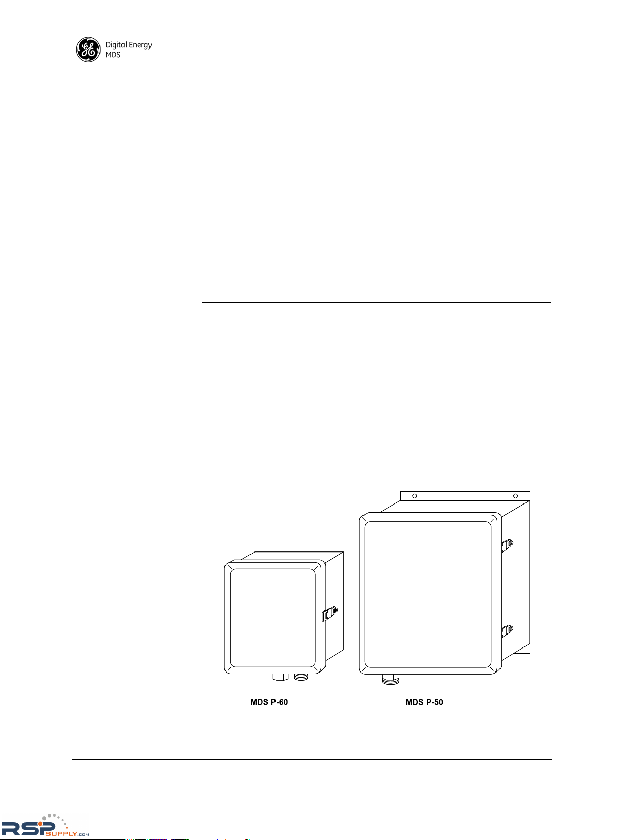
Enclosure Types
Figure 1 shows the two cabinet styles commonly used in the packaged system
family. Each is a gray fiberglass NEMA-approved enclosure.
•The MDS P-60 is a compact model measuring 13.75 inches high x
11.85 inches wide x 6.5 inches deep (35cm x 30.1cm x 16.5cm). This
model has less space inside for mounting of customer equipment, but is
ideal for use in locations where space is limited.
•The MDS P-50 is a discontinued model that is typically contained in a
large enclosure measuring 19.5 inches high x 17.5 inches wide x 9.5
inches deep (49.5cm x 44.5cm x 24.1cm). Extra space in the cabinet
may be used to mount customer-supplied equipment, if desired.
Invisible place holder
Figure 1. GE MDS Packaged Radio Systems
Shown with covers closed
RSPSupply - 1-888-532-2706 - www.RSPSupply.com
http://www.RSPSupply.com/p-8466-MDS-P60-Compact-Enclosure-(One-Radio).aspx
Page 9
MDS 05-2818A01, Rev. C MDS P-60/P-60 HL Reference Manual 9
WARNING! P-60 units installed in a hazardous environment (P-60 HL)
require special installation procedur es in addition to the instructions
provided in this manual. Refer to and comply with P-60 HL Packaged
Radio - Hazardous Locations Installation Procedure (P000530) when
installing these units.
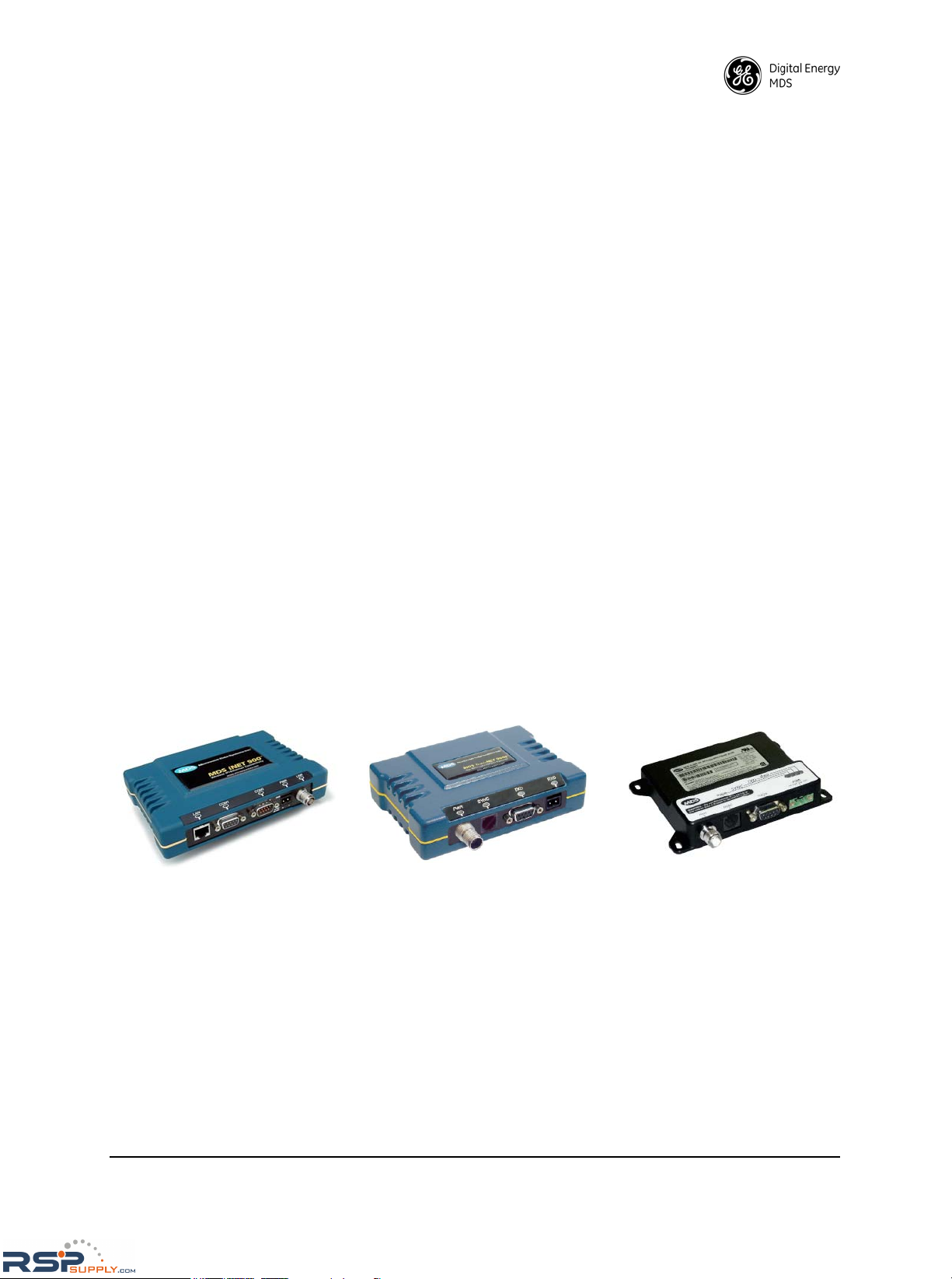
MDS P-60 Units Equipped with MDS iNET or TransNET
Transceivers
The P-60 can be equipped with various transceiver types. Depending on order
requirements, the enclosure might contain one of MDS’ newer generation
transceivers, such as an MDS iNET or MDS TransNET Series. These units are
housed in blue, die-cast aluminum enclosures and are mounted with brackets
that attach to the bottom of the radio and extend out the sides.
In addition to the standard TransNET radio, there is also a board-only version
of this product that can be installed in a P-60. While electrically and operationally similar to the standard (metal-enclosed) TransNET, it does not have a full
enclosure. It is fitted with a non-metallic cover through which four mounting
screws are inserted to secure it to the P-60 plate.
These new generation transceivers are described below:
• The MDS iNET is a license-free IP/Ethernet transceiver measuring
1.50" high x 6.00" wide x 4.00" deep (3.8 x 15.2 x 10.2 cm). (Note:
Only three screws are used to mount MDS iNET models to the P-60
plate.)
• The MDS TransNET is a license-free serial data transceiver measuring
1.40" high x 5.30" wide x 3.50" deep (3.8 x 15.2 x 10.2 cm).
• The MDS TransNET 900 Board-Only transceiver is operationally similar to the standard TransNET, but includes a non-metallic cover, and
measures 1.40" high x 5.30" wide x 3.50" deep (3.8 x 15.2 x 10.2 cm).
Figure 2. MDS iNET and TransNET Transceivers
Primary Power
Packaged systems can be equipped for a variety of AC or DC power supply
requirements. In addition, a 12 volt backup battery is provided as standard
equipment in AC-powered models. The battery provides at least four hours of
operation in the event of a primary power failure. (Depending on the transmit
duty cycle and how often the radio is polled, the battery may last much longer.)
The backup battery is float charged by the power supply during normal system
operation.
MDS TransNET
Transceiver
MDS TransNET
Board-Only Transceiver
MDS iNET IP/Ethernet
Transceiver
RSPSupply - 1-888-532-2706 - www.RSPSupply.com
http://www.RSPSupply.com/p-8466-MDS-P60-Compact-Enclosure-(One-Radio).aspx
Page 10

10 MDS P-60/P-60 HL Reference Manual MDS 05-2818A01, Rev. C
Programming and Diagnostics
Transceiver programming and diagnostics are performed by connecting an
MDS Hand-Held Terminal (HHT) or PC running MDS software. With MDS
P-60
models, an HHT can be plugged directly into the packaged system’s Inter-
face/Utility Board. This eliminates the need for unplugging the data cable from
the transceiver’s
INTERFACE connector. Instructions for connecting a diag-
nostic terminal are given in Section 4.0 P-60/P-50 Operation on Page 39.
Packaged System Specifications*
* Specifications are subject to change without notice. For radio specifications, refer
to the associated transceiver instruction manual.
Enclosure Dimensions:
(excluding hardware)
MDS P-60:
13.75 inches H x 11.85 inches W x 6.5 inches D
(35 x 30.1 x 16.5 cm)
MDS P-50:
19.5 inches H x 17.5 inches W x 9.5 inches D
(49.5 x 44.5 x 24.1 cm)
Approximate Weight:
(with backup battery)
MDS P-60:
21 lb. (9.53 kg)
MDS P-50:
33 lb. (15 kg)
Enclosure Impact Resistance: Tested to 6.78 Joule (5 ft./lb.)
Transceiver types used in packaged systems: MDS x710 Series, MDS x810 Series, MDS
2300/4300/9300 Series, MDS iNET, MDS
TransNET, Mercury, and others
Temperature Range: Full performance: –30°C to +60°C
(Reduced battery life at cold temperatures)
Humidity: 95% at + 40°C Non-Condensing
Primary Power Options: 12, 24, 48, 120 Vdc
120–220 Vac
Typical Supply Current:
(Excluding battery-charging current)
Transmit: 1.8 A @ 5 watts
1.0 A @ 1 watt
Receive: 80 mA maximum
Standby (transceiver in “sleep” mode): <15 mA
Backup Power Provision:
(Standard on AC-powered models.)
12 volt battery
4.6 Ah for P-60 series, 5 Ah for P-50 series
RSPSupply - 1-888-532-2706 - www.RSPSupply.com
http://www.RSPSupply.com/p-8466-MDS-P60-Compact-Enclosure-(One-Radio).aspx
Page 11

MDS 05-2818A01, Rev. C MDS P-60/P-60 HL Reference Manual 11
1.3 Accessories
GE MDS publishes an Accessories Selection Guide which lists a complete
array of additional items available for use with this product. Please contact
your factory representative or visit www.GEmds.com to obtain a copy of this
guide.
Table 1. P-60 Accessories
GE MDS Part Number Description
12-1307A01 Order Wire Handset
02-1501A01 Hand-Held Terminal (Kit P/N 03-1501A01)
82-1982A02 Mounting plate for 19 inch rack; 10.5 inches
high (mounts internal chassis)
Table 2. P-50 Accessories
GE MDS Part Number Description
82-1743A01 Pole-Mount Adapters (two required)
12-1307A01 Order Wire Handset
02-1501A01 Hand-Held Terminal (Kit P/N 03-1501A01)
02-1556A01 Mounting kit for 19 inch rack; 15.75 inches high
(mounts internal chassis)
RSPSupply - 1-888-532-2706 - www.RSPSupply.com
http://www.RSPSupply.com/p-8466-MDS-P60-Compact-Enclosure-(One-Radio).aspx
Page 12

12 MDS P-60/P-60 HL Reference Manual MDS 05-2818A01, Rev. C
2.0 MDS P-60 INSTALLATION
NOTE: Due to restricte d ventilation, the P-60 enclosure is not suitable for
applications using a continuously transmitting radio.
2.1 Unpacking and Inspection
After opening the shipping container, check the contents against the packing
list secured to the outside of the box. We recommend saving all shipping materials in case the unit needs to be shipped in the future.
The factory test data sheet is normally packed with the equipment. Check this
sheet to ensure that the packaged radio system has been configured to meet
your requirements. Specific items to check include: primary power voltage,
transmit and receive frequencies, modem speed (if applicable), FM deviation,
and transmitter RF power output. If there are discrepancies, contact GE MDS’
Customer Support at +1 (585) 242-9600 for assistance.
2.2 Installation Considerations
A short time spent planning the installation can help prevent performance
problems later on. Select a location that provides a stable mounting surface,
and also allows for convenient routing of the antenna, power and data cabling.
All of these cables (but especially the antenna feedline) need to be kept as short
as possible to minimize losses. Refer to the transceiver manual for a feedline
loss chart.
Packaged systems are normally mounted in either a wall-mount or pole-mount
configuration. If possible, install the unit in a location that can be easily
reached while standing on the ground. This allows convenient access for test
and servicing of the radio system.
If the unit must be installed in a location that is not easily accessible, it may be
desirable to first operate the packaged system on a test bench to verify proper
operation with customer-supplied equipment and to set any programmable
parameters before installation. However, installation tasks such as antenna
aiming and SWR checks should be done with the unit placed in its final operating position.
NOTE: The use of stainless steel mounting hardware is recommended for
outdoor installations.
2.3 Mounting the Enclosure
There are two basic mounting arrangements for the MDS P-60—pole mount or
wall mount. Methods for mounting the unit in both of these configurations
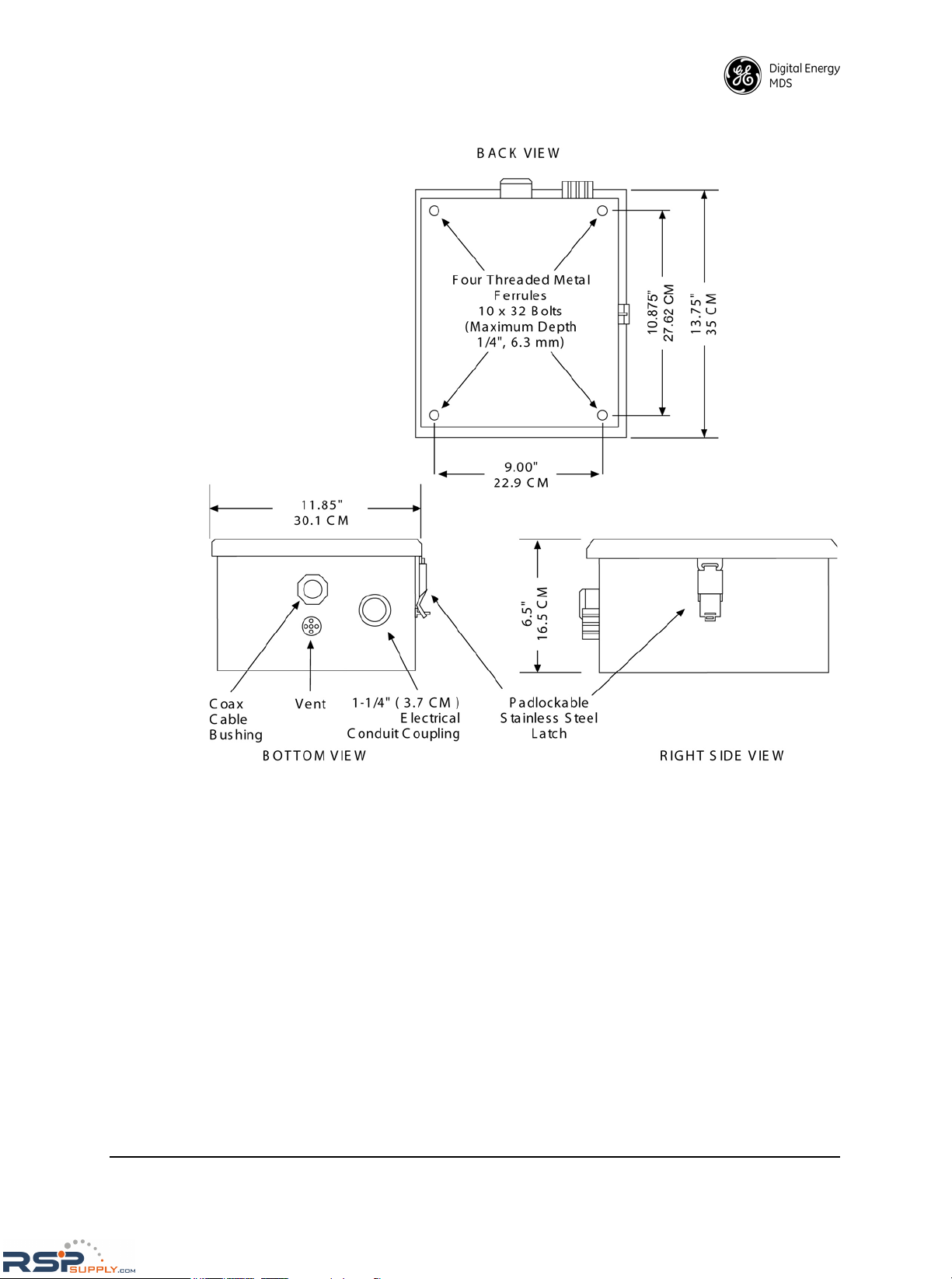
follow. When planning the installation, refer to Figure 3 on Page 13, which
shows the mounting dimensions of the MDS P-60 packaged system.
RSPSupply - 1-888-532-2706 - www.RSPSupply.com
http://www.RSPSupply.com/p-8466-MDS-P60-Compact-Enclosure-(One-Radio).aspx
Page 13
MDS 05-2818A01, Rev. C MDS P-60/P-60 HL Reference Manual 13
Invisible place holder
Figure 3. MDS P-60 Mounting Dimensions
Wall Mounting Instructions
The steps below describe mounting of the MDS P-60 unit to a wall or other flat
surface. Ordinary lag screws (with flat washers) can be used for mounting to a
wooden surface. If it is to be mounted to a drywall, masonry or other
non-wooden surface, suitable fasteners will be required that can support the
weight of the unit.
To wall mount the unit, follow these instructions:
1. Attach the four keyhole mounting clips (provided) to the back of the
enclosure with 10-32 screws, as shown in Figure 4 on Page 14. The
screws must be no longer than 3/8" (9.5 mm). Longer screws will
damage the enclosure.
RSPSupply - 1-888-532-2706 - www.RSPSupply.com
http://www.RSPSupply.com/p-8466-MDS-P60-Compact-Enclosure-(One-Radio).aspx
Page 14

14 MDS P-60/P-60 HL Reference Manual MDS 05-2818A01, Rev. C
2. Hold the packaged unit up to the wall in the desired mounting position.
Have an assistant mark the four mounting holes with a pencil or marker.
(The marks should be placed in the center of the wide portion of the
mounting clips.)
3. Prepare the mounting surface for the fasteners to be used. (If using lag
screws, a small pilot hole at each mark will allow easier starting of the
screw.)
4. Insert the screws part way into the wall, leaving enough space to slide the
enclosure mounting clips onto the screws. Hang the packaged system
enclosure onto the four screws and tighten the screws securely. Do not
over-tighten.
Figure 4 shows a typical wall mount installation.
Figure 4. Typical Wall Mounted Installation (MDS P-60)
TO PRIMARY
POWER
(CONDUIT)
13.38"
34 cm
9.0"
22.86 cm
COAXIAL CABLE
TO ANTENNA
TO DATA
EQUIPMENT
(RTU)
ATTACHED TO BACK
OF MDS xx60
A
ENCLOSURE WITH
10-32 SCREW
(SEE TEXT)
FLAT
WASHER
MOUNTING
CLIP
MOUNTING CLIP DETAIL
(4 REQD)
RSPSupply - 1-888-532-2706 - www.RSPSupply.com
http://www.RSPSupply.com/p-8466-MDS-P60-Compact-Enclosure-(One-Radio).aspx
Page 15

MDS 05-2818A01, Rev. C MDS P-60/P-60 HL Reference Manual 15
Pole Mounting Instructions
Standard pole mounting requires the use of two pole-mount adapters (P/N
82-1743A01). These brackets must first be bolted to the MDS P-60 enclosure.
The complete assembly can then be mounted to a wooden utility pole with two
lag screws or with two long bolts that extend through the pole. (Threaded rod
can also be used for through-the-pole mounting.) In either case, it is important
to use flat washers with the attaching hardware (fasteners are not supplied).
To pole mount the unit, follow these instructions:
1. Attach the two pole-mount adapter brackets to the MDS P-60
enclosure with four 10-32 screws, as shown in
Figure 5. The screws
must be no longer than 3/8" (9.5 mm). Longer screws will damage
the enclosure.
2. With the help of an assistant, position the MDS P-60 enclosure on the pole
at the desired mounting point.
3. Install the attaching hardware (with flat washers) in the center hole of the
two brackets.
4. Tighten the fasteners securely, but do not over-tighten.
Figure 5 shows a typical pole-mount installation with lag screws.
Invisible place holder
Figure 5. Typical Pole-Mounted Installation (MDS P-60)
TO PRIMARY POWER
(CONDUIT)
COAXIAL CABLE
TO ANTENNA
LAG SCREW
FLAT WASHER
(2 REQD)
TO DATA
EQUIPMENT
(RTU)
POLE MOUNT
BRACKET
82-1743A01
(2 REQD)
BRACKET ATTACHED
TO ENCLOSURE
WITH 10-32 SCREWS
(SEE TEXT)
RSPSupply - 1-888-532-2706 - www.RSPSupply.com
http://www.RSPSupply.com/p-8466-MDS-P60-Compact-Enclosure-(One-Radio).aspx
Page 16

16 MDS P-60/P-60 HL Reference Manual MDS 05-2818A01, Rev. C
Other pole-mount hardware is available for the MDS P-60, including a
mounting bracket with a sun shield (for use in excessively hot climates), a
tower mounting bracket, and other arrangements to meet special needs. Contact GE MDS for more information.
Rack Mount Alternative
In addition to wall and pole mounting, the packaged system can also be
mounted in a 19 inch equipment rack for indoor installations. Figure 6 shows
a typical rack mount installation using brackets fabricated from steel or aluminum. Figure 7 on Page 17 details the mounting plate configuration.
The electrical installation procedures given in this section apply fully to rack
mounted units. The physical mounting instructions, however, will differ,
depending on the type of rack cabinet to be used. Contact GE MDS if additional assistance is required.
Invisible place holder
Figure 6. Typical Rack Mount Installation (MDS P-60)
RSPSupply - 1-888-532-2706 - www.RSPSupply.com
http://www.RSPSupply.com/p-8466-MDS-P60-Compact-Enclosure-(One-Radio).aspx
Page 17

MDS 05-2818A01, Rev. C MDS P-60/P-60 HL Reference Manual 17
2.4 MDS P-60 Cable Connections
This section describes the connection of external cabling to the MDS P-60
packaged system. Included are steps for connecting DC power, the station
antenna, and data equipment (RTU) cabling. Figure 7 shows an overall view of
the connection points for all external cabling. Subsequent illustrations will
show more detailed views of wiring connections as required.
Invisible place holder
Figure 7. MDS P-60 Cable Connection Points
Primary Power—TB2
The power input terminations for the MDS P-60 are provided on the Inter-
face/Utility Board connector TB2 via screw terminals (see Figure 8 on
Page 19). Note that TB2 is used for input power regardless of whether the unit
is configured for AC or DC operation. Primary power wiring should be routed
via conduit to the hole on the bottom right of the enclosure. This hole is fitted
with a standard 1-1/4" (3.37 cm) conduit coupling.
CAUTION:
The MDS P-60 is available for operation on a wide variety
of AC or DC supply voltages. Be sure to check the label near TB2 and
make sure that the supply voltage you are using matches that specified
on the label before applying power. Use of an incorrect supply voltage
can permanently damage the radio, power supply, or both.
DC Operation
Connector TB2 is used for primary power input on DC-powered models. Pin 1
is the negative (–) connection. Pin 3 is the positive (+) connection.
BACK-UP BATTERY
CONNECTION (J4)
PRIMARY POWER
CONNECTION (TB2)
DATA EQUIPMENT
CONNECTION (TB1)
ANTENNA
CONNECTION
RSPSupply - 1-888-532-2706 - www.RSPSupply.com
http://www.RSPSupply.com/p-8466-MDS-P60-Compact-Enclosure-(One-Radio).aspx
Page 18

18 MDS P-60/P-60 HL Reference Manual MDS 05-2818A01, Rev. C
The MDS P-60 is normally wired by the factory for “floating” power connections. However, either of the primary power leads can be connected to TB2 Pin
2 (chassis ground), if desired, to configure the unit for positive or negative
ground.
AC Operation
Connector TB2 is used for primary power input on AC-powered models. Pins
1 and 3 are the AC line inputs. The AC Ground must be connected to Pin 2
(chassis ground).
AC power supplies are most commonly wired for 120 Vac, but can readily be
rewired for 230 Vac if desired. There is a chart on the side of the power supply;
unmount the power supply to view it.
Power Supply Bypass Plug
The MDS part number for the Power Supply Bypass plug (used on models
without a DC-DC converter) is 03-1304A01.
Accessory Power—With Analog Interface/Utility Board Installed
Interface terminal block TB1 Pin 12 can be used to provide up to 1 ampere for
13 Vdc negative ground accessories. TB1 Pin 11 is the negative connection.
Fuse F5 provides protection for this accessory power.
Backup Battery—Important information
Packaged systems supplied wired for AC operation have a backup battery
system installed as standard equipment. The battery is disconnected for shipping by unplugging its cable from the Interface/Utility Board. This prevents
accidental discharge of the battery and radio operation while the unit is in shipment or storage. Plug the battery cable into J4 to enable the backup power
option.
Antenna Connection
A type-N coaxial connector on the lower right side of the transceiver chassis
serves as the antenna connection to the packaged system. Route the antenna
coax through the weathertight bushing on the bottom of the enclosure and
attach it to the transceiver connector. This bushing is also commonly used to
pass the RTU interface through to the Interface/Utility Board. Do not tighten it
until all cabling has been installed.
The antenna connection is not made directly to MDS iNET and TransNET
transceivers, as with other MDS radios. A pigtail coaxial lead is provided (P/N
03-3576A01), that makes the antenna connection readily accessible, and converts it from a TNC connector to a Type-N connector. After connecting the
antenna feedline to the pigtail connector, the assembly should be well insulated
(for example, electrical tape or shrink tubing) to prevent contact with other circuitry inside the P-60 housing.
Refer to the transceiver manual for additional information on installing
antennas and feedlines.
NOTE: The following subs ection describes audio and keyline connections
to an MDS P-60 Analog Interface/Utility Board (P/N 03-2110A01).
Instructions for the Digital Interface/Utility Board are given in the
next major subsection.
RSPSupply - 1-888-532-2706 - www.RSPSupply.com
http://www.RSPSupply.com/p-8466-MDS-P60-Compact-Enclosure-(One-Radio).aspx
Page 19
MDS 05-2818A01, Rev. C MDS P-60/P-60 HL Reference Manual 19
2.5 Audio and Keyline Connections—Analog
Interface/Utility Board (P/N 03-2110A01)
The Analog Interface/Utility Board serves as the connection point for all audio
and keyline connections to the MDS P-60. Route the cabling to the Inter-
face/Utility Board through the weathertight bushing on the bottom of the
enclosure (also used for the antenna coaxial cable). Tighten the bushing after
installing the interface cable.
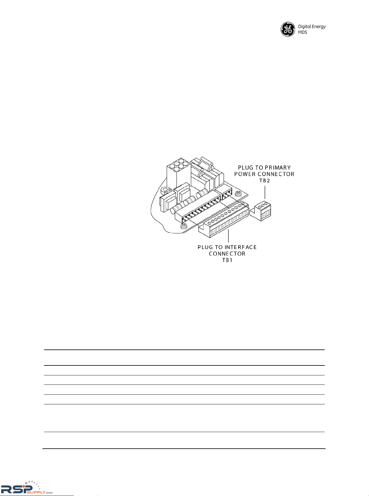
Interface/Utility Board connections are made through two compression-screw-type plug assemblies (see Figure 8). The plug assemblies are
removed by sliding the connectors away from the center of the PC board. There
is a pair of small clips on the plug that prevent the connectors from falling out
of the PCB mounted receptacles.
Invisible place holder
Figure 8. Plugs for Primary Power TB2
and Interface TB1 Connectors
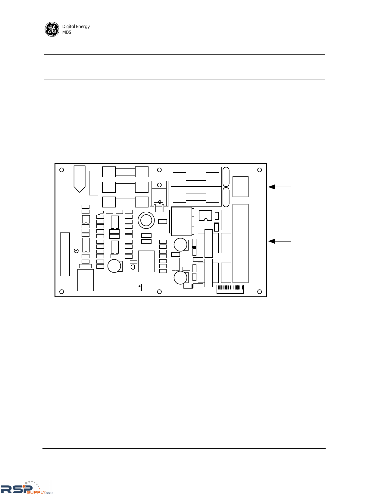
Audio and Keyline—TB1
Connector TB1 on the Analog Interface/Utility Board is used for all audio and
keyline terminations. Table 3 lists the pin assignments for TB1. When making
connections, refer to Figure 9 on Page 20 for a detailed view of the Analog
Interface/Utility Board.
Table 3. Pin Connections (Analog Interface/Utility Board)
TB1
Pins
Connection Remarks
1 & 2 Transmit Audio 600 , balanced
3 Ground
4 & 5 Receive Audio 600 , balanced
6 Ground
7 & 8 Keyline connection for positive or
negative keying
This arrangement allows the radio to be keyed by a variety
of different methods that will accommodate most systems.
For more information, see “Keyline Options” discussion
below.
RSPSupply - 1-888-532-2706 - www.RSPSupply.com
http://www.RSPSupply.com/p-8466-MDS-P60-Compact-Enclosure-(One-Radio).aspx
Page 20
20 MDS P-60/P-60 HL Reference Manual MDS 05-2818A01, Rev. C
Invisible place holder
Figure 9. Analog Interface/Utility Board, P/N 03-2110A01
Keyline Options
Several methods may be used to key the transceiver, depending on the facilities
available at the installation site and the design of the customer-supplied data
equipment. (See Figure 10 on Page 22.) This section discusses three common
keying methods. Contact the factory if further assistance is required.
Positive or Negative Keying
One keyline option is to use a keyed 12 to 25 volt source or a fixed voltage
source and a series relay. The relay contacts can be included in either the positive or negative supply lead. (See Figure 10 on Page 22, examples 1 and 2.)
The use of an opto-isolator allows both keying supply leads to “float” above or
below ground, and tolerates line to ground transients up to 2500 volts. TB1 Pin
7 must be positive with respect to TB1 Pin 8. For keying supply voltages higher
than 25 volts, add a resistor in series with the connection to TB1 Pin 7 or TB1
Pin 8 to limit the keying current to 10 to 20 mA.
9 AC Alarm Normally 11 Vdc; drops to zero volts if an AC failure occurs.
10 Received Signal Strength
Indication (RSSI)
Approximately 0 to 5 Vdc through a 10K resistor.
8 & 11 Keyline connection when an
internal current source is used.
(Requires a jumper between Pins
7 and 12.)
This method uses the on-board 12 volt DC supply. For more
information, see “Keyline Options” discussion below.
12 +13 Vdc Accessory power (1 Amp maximum). Jumpered to Pin 7 for
keying with an internal current source. See description for
Pins 8 & 11 above.
Table 3. Pin Connections (Analog Interface/Utility Board) (Continued)
TB1
Pins
Connection Remarks
LINE 2/DC +
NEUTRAL
LINE 1/DC
+13V ACCY
GND
RSSI
AC ALARM
KEYLINE LO
KEYLINE HI
GND
RX AUDIO
RX AUDIO
GND
TX AUDIO
TX AUDIO
2
3
1
00-00000-00
POWER
CONNECTIONS
(TB2)
INTERFACE
CONNECTIONS
(TB1)
1
2
3
4
5
6
7
8
9
10
11
12
1
2
3
J5
J4
J7
F5
F4
F3
J3
J2
J6
J1
F1
F2
T2
T1
TB1
TB2
MOV1
MOV2
26
25
2
1
25
RSPSupply - 1-888-532-2706 - www.RSPSupply.com
http://www.RSPSupply.com/p-8466-MDS-P60-Compact-Enclosure-(One-Radio).aspx
Page 21

MDS 05-2818A01, Rev. C MDS P-60/P-60 HL Reference Manual 21
Internal Current Source Keying
Another keyline option is to use the on-board 12 volt DC supply. This is done
by adding a jumper from TB1 Pin 7 to Pin 12. TB1 Pins 8 and 11 should then
be connected to the keyline relay contacts. (See Figure 10 on Page 22, example
3.)
Manual Keying Button (for test purposes)
A red pushbutton switch, SW1, is provided on the Interface/Utility Board to
key the transmitter manually when desired. This is intended for use during initial setup and testing of the packaged system.
NOTE: The Transmit Test Key, SW1, on the Interface/Utility Board is
non-functional with MDS iNET or TransNET radios.
Additional Interface Connections
Two unique outputs are provided on TB1 for custom applications: AC power
failure alarm, and the transceiver’s Received Signal Strength Indication
(RSSI).
AC Alarm —Pin 9
H = AC Present—Approximately 11 Vdc through a 1 K
resistor
L = AC Failure—Ground through a 1 K resistor
Received Signal Strength Indicator (RSSI)—Pin 10
Same as transceiver’s RSSI output. It provides a DC voltage proportional to the
received signal strength. The range is approximately zero to five volts DC
through a 10K current limiting resistor. Refer to the transceiver manual for
additional RSSI information.
For MDS iNET and TransNET Radios
The Orderwire and Diagnostic connectors on the Interface/Utility Board are
not used when MDS iNET or TransNET radios are installed. Orderwire and
diagnostic connections must be made directly at the radio, using appropriately
wired connectors. Refer to the transceiver manual for pinout information.
The TransNET’s Sleep and Alarm lines are not carried onto the P-60 terminal
strip, J1/TB1. If these functions are required, make the connection directly at
the radio, using an appropriately wired connector.
Two interface cables are packed inside each P-60 when an MDS iNET or
TransNET radio is installed. The proper cable must be identified by the user
and installed between the radio’s DB-9 data connector and J2 on the Interface/Utility Board.
• The 03-2848A01 cable is for use with an iNET radio’s COM2 port.
• The 03-2876A01 cable is for use with either a TransNET radio, or an
iNET radio’s COM1 port.
P-60 units with an MDS iNET transceiver installed include an Ethernet Transient Protector that is mounted at the bottom of the enclosure. A heavy ground
wire (green) extends between the stud on the protector, and the P-60’s ground
point.
RSPSupply - 1-888-532-2706 - www.RSPSupply.com
http://www.RSPSupply.com/p-8466-MDS-P60-Compact-Enclosure-(One-Radio).aspx
Page 22

22 MDS P-60/P-60 HL Reference Manual MDS 05-2818A01, Rev. C
Invisible place holder
Figure 10. Keying Options, Analog Interface/Utility Board, P/N 03-2110A01
RSPSupply - 1-888-532-2706 - www.RSPSupply.com
http://www.RSPSupply.com/p-8466-MDS-P60-Compact-Enclosure-(One-Radio).aspx
Page 23

MDS 05-2818A01, Rev. C MDS P-60/P-60 HL Reference Manual 23
2.6 Data Connections—Digital Interface/
Utility Board (P/N 03-2472Axx)
The Digital Interface/Utility Board serves as the connection point for all data
connections to the MDS P-60. Route the cabling to the Interface/Utility Board
through the weathertight bushing on the bottom of the enclosure (also used for
the antenna coaxial cable). Tighten the bushing after installing the interface
cable.
Interface/Utility Board connections are made through two compression-screw-type plug assemblies. The plug assemblies are removed by sliding
the connectors away from the center of the PC board. There is a pair of small
clips on the plug that prevent the connectors from falling out of the PCB
mounted receptacles.
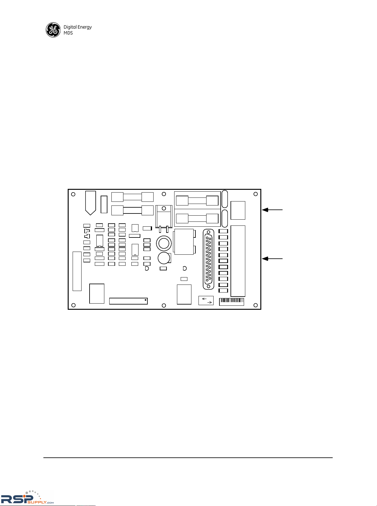
RS-232/EIA-232 Data Connections—TB1
Table 4 lists the functions of the RS-232/EIA-232 pins on TB1 of the Digital
Interface/Utility Board. When making connections, refer to Figure 11 on
Page 24 for a detailed view of the Digital Interface/Utility Board.
*DSR wired to +8 V in the transceiver.
†
Not applicable for x710 or x810 radios, which are asynchronous
NOTES
1. The radio is configured as DCE (Data Circuit-terminating Equipment)
as opposed to DTE (Data Terminal Equipment).
2. These lines are inputs: ETC, TXD and RTS.
3. These lines are outputs: TC, RC, RXD, CTS, DSR and DCD.
4. For asynchronous operation, make no connection to Pins 8, 9 or 10.
Table 4. Interface/Utility Board TB1 Connections
Pin Number and Function
1. Signal & Protective Ground (usually pin 1)
2. Transmit Data In (TXD)
3. Received Data Out (RXD)
4. Request-To-Send (RTS)
5. Clear-To-Send (CTS)
6. Data Set Ready (DSR)*
7. Data Carrier Detect (DCD)
8. Transmit Clock (TC) Synchronous Operation Only
†
9. Receive Clock (RC) Synchronous Operation Only
†
10. External Transmit Clock (ETC) Synchronous Operation
Only
†
11. Received Signal Strength (RSSI)
12. AC Alarm (AC Failure)
RSPSupply - 1-888-532-2706 - www.RSPSupply.com
http://www.RSPSupply.com/p-8466-MDS-P60-Compact-Enclosure-(One-Radio).aspx
Page 24
24 MDS P-60/P-60 HL Reference Manual MDS 05-2818A01, Rev. C
Additional Interface Connections
Two additional outputs are provided on TB1 for custom applications: AC
power failure alarm, and the transceiver’s Received Signal Strength Indication
(RSSI).
AC Alarm —Pin 12
H = AC Present—Approximately 11 Vdc through a 1 K
resistor
L = AC Failure—Ground through a 1 K resistor
Received Signal Strength Indicator (RSSI)—Pin 11
Same as transceiver’s RSSI output. It provides a DC voltage proportional to the
received signal strength. The range is approximately zero to five volts DC
through a 10K current limiting resistor. Refer to the transceiver manual for
additional RSSI information.
Invisible place holder
Figure 11. Digital Interface/Utility Board, P/N 03-2472Axx
00-00000-00
LINE 2/DC+
NEUTRAL
LINE 1/DC
AC ALARM
RSSI
ETC
RC
TC
DCD
DSR
CTS
RXD
TXD
GND
2
3
1
POWER
CONNECTIONS
(TB2)
INTERFACE
CONNECTIONS
(TB1)
RTS
1
2
3
4
5
6
7
8
9
12
10
11
1
2
3
J4
J7
F4
F3
F1
F2
J5
J1
J2
J6
J3
OUT
IN
SW2
26 25
21
2
TB1
TB2
MOV1 MOV2
RSPSupply - 1-888-532-2706 - www.RSPSupply.com
http://www.RSPSupply.com/p-8466-MDS-P60-Compact-Enclosure-(One-Radio).aspx
Page 25

MDS 05-2818A01, Rev. C MDS P-60/P-60 HL Reference Manual 25
2.7 Final MDS P-60 Installation Tasks
Perform the following steps to complete the installation of the MDS P-60 and
prepare the unit for normal operating service:
1. Dress and secure all external cabling in conformance with
applicable electrical codes.
2. Apply primary power to the unit and check for normal transceiver operation. (Checks for the radio are described in the transceiver manual.)
3. If necessary, refine the antenna heading for maximum RSSI. Refer to the
transceiver manual for additional RSSI information.
4. Close and latch the equipment cabinet. The cabinet latch may be padlocked if desired.
RSPSupply - 1-888-532-2706 - www.RSPSupply.com
http://www.RSPSupply.com/p-8466-MDS-P60-Compact-Enclosure-(One-Radio).aspx
Page 26

26 MDS P-60/P-60 HL Reference Manual MDS 05-2818A01, Rev. C
3.0 MDS P-50 INSTALLATION
NOTE: The MDS P-50 is a discontinued pro duct, an d is pro vided in th is
manual for historical reference only.
3.1 Unpacking and Inspection
After opening the shipping container, check the contents against the packing
list secured to the outside of the box. We recommend that all shipping materials
be saved in case you need to ship the unit in the future.
The factory test data sheet is normally packed with the equipment. Check this
sheet to ensure that the packaged radio system has been configured to meet
your requirements. Specific items to check include: primary power voltage,
transmit and receive frequencies, modem speed (if applicable), FM deviation,
and transmitter RF power output. If there are discrepancies, contact GE MDS
Customer Support at +1 (585) 242-9600 for assistance.
3.2 Installation Considerations
A short time spent planning the installation can help prevent performance
problems later on. Select a location that provides a stable mounting surface,
and also allows for convenient routing of the antenna, power and data cabling.
All of these cables (but especially the antenna feedline) need to be kept as short
as possible to minimize losses. Refer to the transceiver manual for further
information on selecting feedlines.
Packaged systems are normally mounted in either a wall-mount or pole-mount
configuration. If possible, install the unit in a location that can be easily
reached while standing on the ground. This allows convenient access for test
and servicing of the radio system.
If the unit must be installed in a location that is not easily accessible, it may be
desirable to first operate the packaged system on a test bench to verify proper
operation with customer-supplied equipment and to set any programmable
parameters before final installation. However, installation tasks such as
antenna aiming and SWR checks should be done with the unit in its permanent
operating position.
NOTE: The use of stainless steel mounting hardware is recommended for
outdoor installations.
3.3 Mounting the Enclosure
There are two basic mounting arrangements for the MDS P-50—wall mount or
pole mount. The steps below describe methods for mounting the unit in both of
these standard configurations. When planning the installation, refer to
Figure 12 on Page 27, which shows the mounting dimensions of the MDS P-50
packaged system.
RSPSupply - 1-888-532-2706 - www.RSPSupply.com
http://www.RSPSupply.com/p-8466-MDS-P60-Compact-Enclosure-(One-Radio).aspx
Page 27

MDS 05-2818A01, Rev. C MDS P-60/P-60 HL Reference Manual 27
Invisible place holder
Figure 12. MDS P-50 Mounting Dimensions
Wall Mounting Instructions
The steps below describe mounting of the MDS P-50 unit to a wall or other flat
surface. Ordinary lag screws (with flat washers) can be used if the unit is to be
mounted to a wooden surface. If it is to be mounted to a drywall, masonry or
other non-wooden surface, suitable fasteners will be required that can support
the weight of the unit.
To wall mount the unit, follow these instructions:
1. Hold the packaged unit up to the wall in the desired mounting
position. Have an assistant mark the four mounting holes with a
pencil or marker.
2. Prepare the mounting surface for the fasteners to be used. (If using lag
screws, a small pilot hole at each mark will allow easier starting of the
screw.)
3. Hold the packaged unit up to the wall again while an assistant installs the
four mounting screws. Make sure the screws are tightened securely, but do
not over-tighten.
Figure 13 on Page 28 shows a typical wall mount installation.
RSPSupply - 1-888-532-2706 - www.RSPSupply.com
http://www.RSPSupply.com/p-8466-MDS-P60-Compact-Enclosure-(One-Radio).aspx
Page 28

28 MDS P-60/P-60 HL Reference Manual MDS 05-2818A01, Rev. C
Invisible place holder
Figure 13. Typical Wall Mount Installation (MDS P-50)
Pole Mounting Instructions
Standard pole mounting requires the use of two pole-mount adapters (P/N
82-1743A01). These brackets must first be bolted to the MDS P-50 enclosure.
The complete assembly can then be mounted to a wooden utility pole with two
lag screws or with two long bolts that extend through the pole. (Threaded rod
can also be used for through-the-pole mounting.) In either case, it is important
to use flat washers with the attaching hardware (fasteners are not supplied).
To pole mount the unit, follow these instructions:
1. Attach the two pole mount adapter brackets to the MDS P-50
enclosure with suitable nut and bolt assemblies, as shown in
Figure 14 on Page 29.
2. With the help of an assistant, position the MDS P-50 enclosure on the pole
at the desired mounting point.
3. Install the attaching hardware (with flat washers) in the center hole of the
two brackets.
4. Tighten the fasteners securely, but do not over-tighten.
TO PRIMARY POWER
(CONDUIT)
COAXIAL CABLE
TO ANTENNA
LAG SCREW
FLAT WASHER
TO DATA EQUIPMENT (RTU)
(4 REQD)
RSPSupply - 1-888-532-2706 - www.RSPSupply.com
http://www.RSPSupply.com/p-8466-MDS-P60-Compact-Enclosure-(One-Radio).aspx
Page 29

MDS 05-2818A01, Rev. C MDS P-60/P-60 HL Reference Manual 29
Figure 14 shows a typical pole-mount installation using lag screws.
Invisible place holder
Figure 14. Typical Pole-Mounted Installation (MDS P-50)
Other pole-mount configurations are available for the MDS P-50, including a
mounting bracket with a sun shield (for use in excessively hot climates), a
tower mounting bracket, and other arrangements to meet special needs. Contact GE MDS for more information.
Rack Mount Alternative
In addition to wall and pole mounting, the internal chassis of the packaged
system can also be mounted in a standard 19 inch equipment rack for indoor
installations. The rack-mounted model is normally shipped without an enclosure and is supplied with hardware for mounting the chassis plate to the rack
cabinet. Figure 15 on Page 30 shows a typical rack mount installation, and
Figure 16 on Page 31 details the mounting plate configuration.
TO PRIMARY POWER
(CONDUIT)
COAXIAL CABLE
TO ANTENNA
LAG SCREW
FLAT WASHER
(2 REQD)
TO DATA
EQUIPMENT (RTU)
POLE MOUNT
BRACKET
82-1743A01
(2 REQD)
NUT & BOLT ASSEMBLY
(4 REQD)
RSPSupply - 1-888-532-2706 - www.RSPSupply.com
http://www.RSPSupply.com/p-8466-MDS-P60-Compact-Enclosure-(One-Radio).aspx
Page 30

30 MDS P-60/P-60 HL Reference Manual MDS 05-2818A01, Rev. C
The electrical installation procedures given in this section apply fully to rack
mounted units. The physical mounting instructions, however, will differ
depending on the type of rack cabinet to be used. Contact GE MDS if additional assistance is required.
Invisible place holder
Figure 15. Typical Rack Mount Installation (MDS P-50)
POWER, DATA &
ANTENNA CABLING
PACKAGED SYSTEM
CHASSIS PLATE
RSPSupply - 1-888-532-2706 - www.RSPSupply.com
http://www.RSPSupply.com/p-8466-MDS-P60-Compact-Enclosure-(One-Radio).aspx
Page 31

MDS 05-2818A01, Rev. C MDS P-60/P-60 HL Reference Manual 31
3.4 MDS P-50 Cable Connections
This section describes the connection of external cabling to the MDS P-50
packaged system. Included are steps for connecting DC power, the station
antenna, and the customer-supplied equipment. Figure 16 shows an overall
view of the connection points for all external cabling. Subsequent illustrations
will show more detailed views of wiring connections as required.
Invisible place holder
Figure 16. MDS P-50 Cable Connection Points
Primary Power—J3
The power input terminations for the MDS P-50 are provided on the Inter-
face/Utility Board connector J3. Note that J3 is used for input power regardless
of whether the unit has been configured for AC or DC operation. Primary
power wiring should be routed via conduit to the rear hole on the bottom of the
enclosure. This hole is fitted with a standard 1-1/4" (3.37 cm) conduit coupling.
CAUTION:
The MDS P-50 is available for operation on a wide variety
of AC or DC supply volta ges. Be sure to check the label near J3 and
make sure that the supply voltage you are using matches that specified
on the label before applying power. The use of an incorrect supply voltage can permanently damage the radio, power supply, or both.
DC Input—J3
Connector J3 is used for primary power input on DC-powered models. Pin 1 is
the positive (+) connection. Pin 3 is the negative (–) connection.
The system can be configured for negative or positive chassis ground by connecting either the negative or positive supply lead to J3 Pin 2 (chassis ground
terminal). As an alternative, the DC supply leads can be left “floating” by
making no connection to J3 Pin 2.
AC Input—J3
Connector J3 is used for primary power input on AC-powered models. J3 Pins
1 and 3 are the AC line inputs. The AC Ground must be connected to J3 Pin 2
(chassis ground terminal).
RSPSupply - 1-888-532-2706 - www.RSPSupply.com
http://www.RSPSupply.com/p-8466-MDS-P60-Compact-Enclosure-(One-Radio).aspx
Page 32

32 MDS P-60/P-60 HL Reference Manual MDS 05-2818A01, Rev. C
AC power supplies are most commonly wired for 120 Vac, but can readily be
rewired for 230 Vac if desired. There is a chart on the side of the power supply;
unmount the power supply to view it.
Accessory DC Power Out—J8
Accessory Power connector J8 on the Interface/Utility Board can be used to
provide up to 2 amperes at 13 Vdc negative ground for accessories. Fuse F2
provides over-current protection for this power.
Pin 1 of J8 is connected to the +13 volt DC supply. Pin 2 is at DC ground.
Backup Battery—Important information
Packaged systems supplied wired for AC operation have a backup battery
system installed as standard equipment. The battery is disconnected for shipping by unplugging its cable from the Interface/Utility Board. This prevents
accidental discharge of the battery and radio operation while the unit is in shipment or storage. Plug the battery cable into J4 to enable the backup power
option.
Antenna Connection
A type-N coaxial connector on the lower right side of the transceiver chassis
serves as the antenna connection to the packaged system. Route the antenna
coax through the front hole (a weathertight bushing) on the bottom of the
enclosure and attach it to the transceiver connector. This bushing is also commonly used to pass the RTU interface cabling through to the Interface/Utility
Board. Do not tighten it until all cabling has been installed.
Refer to the transceiver manual for additional information on selecting and
installing antennas and feedlines.
NOTE: The following subs ection describes audio and keyline connections
to an MDS P-50 Analog Interface/Utility Board (P/N 03-1105A21).
Instructions for the Digital Interface/Utility Board are given in the
next major subsection.
3.5 Analog Interface/Utility Board Connections
(P/N 03-1105A21)
The Analog Interface/Utility Board serves as the connection point for all audio
and keyline connections to the MDS P-50. Route the cabling to the Inter-
face/Utility Board through the weathertight bushing on the bottom of the
enclosure (also used for the antenna coaxial cable). Tighten the bushing after
installing the interface cable.
RSPSupply - 1-888-532-2706 - www.RSPSupply.com
http://www.RSPSupply.com/p-8466-MDS-P60-Compact-Enclosure-(One-Radio).aspx
Page 33

MDS 05-2818A01, Rev. C MDS P-60/P-60 HL Reference Manual 33
Connector J1 on the Analog Interface Utility Board is used for all audio and
keyline terminations. Refer to Table 5 for a summary of J1 pin connections.
Figure 17 shows a detailed view of the Analog Interface/Utility Board.
Figure 17. Analog Interface/Utility Board Connections—MDS P-50
Table 5. J1 Pin Connections (Analog Interface/Utility Board)
J1
PINS
CONNECTION REMARKS
1 & 2 Transmit Audio 600 , balanced
3 No Connection
4 & 5 Receive Audio 600 , balanced
6 No Connection
7 & 8 Keyline connection for positive or negative
keying
This arrangement allows the radio to be keyed
by a variety of different methods that will
accommodate most systems.
See “Keyline
Options” on Page 34.
8 & 11 Keyline connection when an internal current
source is used. (Requires a jumper between
Pins 7 and 10.)
This method uses the on-board 12 volt DC
supply.
See “Keyline Options” on Page 34.
9 AC Failure Alarm Normally 11 Vdc; drops to zero volts if an AC
failure occurs.
10 +13 Vdc Accessory power (2 Amp maximum) jumpered
to Pin 7 for keying with an internal current
source. See description for Pins 8 & 11 above.
11 PCB ground connection Connects to ground on the Interface/Utility
Board.
12 Received Signal Strength Indication (RSSI) Approximately 0 to 5 Vdc through a 10K
resistor.
RSPSupply - 1-888-532-2706 - www.RSPSupply.com
http://www.RSPSupply.com/p-8466-MDS-P60-Compact-Enclosure-(One-Radio).aspx
Page 34

34 MDS P-60/P-60 HL Reference Manual MDS 05-2818A01, Rev. C
Keyline Options
Several methods may be used to key the transceiver, depending on the facilities
available at the installation site and the design of the customer-supplied data
equipment. (See Figure 18 on Page 35.) This section discusses three common
keying methods. Contact the factory if additional assistance is required.
Positive or Negative Keying
One keyline option is to use a keyed 12 to 25 volt source or a fixed voltage
source and series relay. The relay contacts can be included in either the positive
or negative supply lead (see Figure 18 on Page 35, examples 1 and 2). The use
of an opto-isolator allows both keying supply leads to “float” above or below
ground. J1 Pin 7 must be positive with respect to J1 Pin 8. For keying supply
voltages higher than 25 volts, add a resistor in series with the connection to J1
Pin 7 (or Pin 8) to limit the keying current to 10 to 20 mA.
Internal Current Source Keying
Another keyline option is to use the on-board 12 volt DC supply. This is done
by adding a jumper from J1 Pin 7 to Pin 10. J1 Pins 8 and 11 are then connected
to the keyline relay contacts (see Figure 18 on Page 35, example 3).
Manual Keying Button (for test purposes)
A red pushbutton, SW1, is provided on the Interface/Utility Board to key the
transmitter manually when desired. This is useful during initial setup and
testing of the packaged system.
Additional Interface Connections
Two additional outputs are provided on J1 for custom applications: AC power
failure alarm, and the transceiver’s Received Signal Strength Indication
(RSSI).
AC FAIL—Pin 9
H = AC Present—Approximately 11 Vdc through a 1 K
resistor
L = AC Failure—Ground through a 1 K resistor
RSSI—Pin 12
Same as transceiver’s RSSI output. Provides a DC voltage proportional to the received signal strength. Range is approximately
zero to five volts DC through a 10K current limiting resistor.
Refer to the transceiver manual for additional RSSI information.
RSPSupply - 1-888-532-2706 - www.RSPSupply.com
http://www.RSPSupply.com/p-8466-MDS-P60-Compact-Enclosure-(One-Radio).aspx
Page 35

MDS 05-2818A01, Rev. C MDS P-60/P-60 HL Reference Manual 35
Figure 18. Keying Options—Analog Interface/Utility Board, P/N 03-1105A21
RSPSupply - 1-888-532-2706 - www.RSPSupply.com
http://www.RSPSupply.com/p-8466-MDS-P60-Compact-Enclosure-(One-Radio).aspx
Page 36

36 MDS P-60/P-60 HL Reference Manual MDS 05-2818A01, Rev. C
3.6 Digital Interface/Utility Board Connections
(P/N 03-1467A21)
The Digital Interface/Utility Board serves as the connection point for all data
interface cabling to the MDS P-50. Route the cabling to the Interface/Utility
Board through the weathertight bushing on the bottom of the enclosure (also
used for the antenna coaxial cable). Tighten the bushing after installing the
interface cable.
Connector J1 on the Digital Interface/Utility Board is used for all data cabling
terminations. Refer to Table 6 for a summary of the required pin connections.
Figure 19 on Page 37 shows a detailed view of the Digital Interface/Utility
Board.
*DSR wired to +8 V in the transceiver.
†
Not applicable for x710 or x810 radios, which are asynchronous
NOTES
1. The radio is configured as DCE (Data Communications Equipment) as opposed to
DTE (Data Terminal Equipment).
2. These lines are inputs: ETC, TXD and RTS.
3. These lines are outputs: TC, RC, RXD, CTS, DSR and DCD.
4. For asynchronous operation, make no connection to Pins 8, 9 or 10.
Table 6. Interface/Utility Board J1 Connections
Pin Number & Description Pin Number & Description
1. Signal & Protective Ground 7. Data Carrier Detect (DCD)
2. Transmit Data In (TXD) 8. Transmit Clock (TC)
Synchronous Operation Only
†
3. Received Data Out (RXD) 9. Receive Clock (RC)
Synchronous Operation Only
†
4. Request-To-Send (RTS) 10. External Transmit Clock (ETC)
Synchronous Operation Only
†
5. Clear-To-Send (CTS) 11. Received Signal Strength
(RSSI)
6. Data Set Ready (DSR)* 12. AC Failure (Alarm)
RSPSupply - 1-888-532-2706 - www.RSPSupply.com
http://www.RSPSupply.com/p-8466-MDS-P60-Compact-Enclosure-(One-Radio).aspx
Page 37

MDS 05-2818A01, Rev. C MDS P-60/P-60 HL Reference Manual 37
Invisible place holder
Figure 19. Digital Interface/Utility Board Connections—MDS P-50
Additional Interface Connections
Two additional outputs are provided on J1 for custom applications: AC power
failure alarm, and the transceiver’s Received Signal Strength Indication
(RSSI).
AC FAIL—Pin 12
H = AC Present—Approximately 11 Vdc through a 1 K
resistor
L = AC Failure—Ground through a 1 K resistor
SGN-STRENGTH (RSSI)—Pin 11
Same as transceiver’s RSSI output. Provides a DC voltage proportional to the received signal strength. Range is approximately
zero to five volts DC through a 10K resistor. Refer to the transceiver manual for additional RSSI information.
+
–
BATTERY
PACK
RED
BLACK
FUSE
DIGITAL
INTERFACE
ASSEMBLY
SYSTEM
GROUNDSTUD
DATA
INTERFACE
PRIMARY
POWER
ANTENNA
TRANSMISSION LINE
POWER
SUPPLY
J7
J4
1
1
J8
1
F2
J2
1
J1
1
J6
J5+–
F1
MOV1 MOV2
J3
1
3
46
+
+
+
+
J10
+
J9
PRIMARY POWER
INPUT (AC or DC as
indicated on c hassis
label.)
+–
13 VDC
+
–
RS-232
INTERFACE
CONNECTOR
J1
25 26
2
CHASSIS
GROUND
+–
2345 678910 11 12
12345 678910
T
R
A
N
S
C
E
I
V
E
R
E
T
C
R
C
T
C
D
C
D
D
S
R
C
T
S
R
T
S
R
X
D
T
X
D
G
N
D
A
C
F
A
I
L
S
G
N
S
T
R
E
N
G
T
H
RESERVED FOR RS-422
(CONSULT FACTORY)
RSPSupply - 1-888-532-2706 - www.RSPSupply.com
http://www.RSPSupply.com/p-8466-MDS-P60-Compact-Enclosure-(One-Radio).aspx
Page 38

38 MDS P-60/P-60 HL Reference Manual MDS 05-2818A01, Rev. C
3.7 Final MDS P-50 Installation Tasks
Perform the following steps to complete the installation of the MDS P-50 and
prepare the unit for normal operating service:
1. Dress and secure all external cabling in conformance with
applicable electrical codes.
2. Apply primary power to the unit and check for normal transceiver operation. (Checks for the radio are described in the transceiver manual.)
3. Close and latch the equipment cabinet. The cabinet latches may be padlocked if desired.
4. If necessary, refine the antenna heading for maximum RSSI. (Refer to the
transceiver manual for additional RSSI information.)
RSPSupply - 1-888-532-2706 - www.RSPSupply.com
http://www.RSPSupply.com/p-8466-MDS-P60-Compact-Enclosure-(One-Radio).aspx
Page 39

MDS 05-2818A01, Rev. C MDS P-60/P-60 HL Reference Manual 39
4.0 P-60/P-50 OPERATION
4.1 Introduction
The packaged systems are designed for unattended field operation. The only
normal operator interaction is to apply power at the time of installation and
observe the unit for proper LED indications. This chapter discusses the steps
for initial power-up and also describes the connection of accessory equipment
to the packaged system. These instructions assume that the unit has been
installed in accordance with the installation procedures given earlier in this
manual.
4.2 Initial Power-Up
As soon as primary power is applied to the packaged system, the unit is ready
for operation. Follow these steps to begin operation:
1. Apply primary power to the packaged system.
2. Observe for normal operation. Typically, the radio will be transmitting
intermittently in response to polling signals from the master station. The
transceiver instruction manual describes other installation checks that can
be made to the radio and antenna system.
Battery Backup Operation—for AC-powered units
In AC-powered units, a 12 volt battery is provided as standard equipment. The
battery provides at least four hours of continued operation in the event of a primary power failure. (Depending on the transmit duty cycle and how often the
radio is polled, the battery may last much longer.) The battery is float charged
by the power supply during normal operation.
During battery backup operation, an
AC FAIL LED illuminates on the Inter-
face/Utility Board. (On DC-powered units, this LED will be lit continuously
under normal conditions.) A test procedure for the backup battery is given in
Backup Battery Testing on page 48.
NOTE: Packaged systems supplied wired for AC operation have a backup
battery system installed as stan dard eq uipment. The ba ttery is
disconnected for shipping by un plugging its cable from the Interface/Utility Board. This prevents accidental discharge of the battery
and radio operation while the unit is in shipment or storage. Plug the
battery cable into J4 to enable the backup power option.
Low Voltage Disconnect Assembly
A Low Voltage Disconnect Assembly (P/N 03-3077A01) is included in many
recently manufactured packaged radio systems. This section explains the operation of the assembly and provides schematic and component location information.
A field upgrade kit (P/N 03-3077A11) is also available to add the Low Voltage
Disconnect Assembly to older packaged radio units. Contact GE MDS for
additional information.
RSPSupply - 1-888-532-2706 - www.RSPSupply.com
http://www.RSPSupply.com/p-8466-MDS-P60-Compact-Enclosure-(One-Radio).aspx
Page 40

40 MDS P-60/P-60 HL Reference Manual MDS 05-2818A01, Rev. C
Functional Description
The Low Voltage Disconnect assembly is a small PC board mounted on the
chassis plate of GE MDS packaged model radio systems. It prevents battery
damage that may be caused by allowing a backup battery to drop below 10.2
volts while powering a transceiver, such as might occur during a lengthy power
outage. Component locations are shown in Figure 20, and Figure 21 provides
a schematic diagram.
When the battery voltage drops to 10.2 Volts (± 0.2V), the Low Voltage Disconnect Assembly automatically disconnects the battery from the transceiver.
This, of course, stops operation of the radio, but protects the battery from
potential damage. When AC power returns, the battery is automatically connected to the power supply (for charging) and normal radio operation resumes
immediately.
Invisible place holder
Figure 20. Low Voltage Disconnect Assembly, P/N 03-3077A01
Component Locations
RSPSupply - 1-888-532-2706 - www.RSPSupply.com
http://www.RSPSupply.com/p-8466-MDS-P60-Compact-Enclosure-(One-Radio).aspx
Page 41

MDS 05-2818A01, Rev. C MDS P-60/P-60 HL Reference Manual 41
Invisible place holder
Figure 21. Low Voltage Disconnect Assembly, P/N 03-3077A01
Schematic Diagram
Use of the Battery Reset Switch (SW1)
Normally, the operation of the Low Voltage Disconnect Assembly is fully
automatic. The only exception is when replacing a discharged battery with a
charged unit before AC power has returned. In this case, it is necessary to press
the
BAT. RESET switch on the assembly after installing the new battery. (See
Figure 22.) Use a pen or other pointed object to press the switch. This allows
the replacement battery to immediately supply power to the transceiver.
Invisible place holder
Figure 22. Low Voltage Disconnect Assembly
NOTE: For proper opera tion of the Low V oltage Disconnect assembly,
14.10 Vdc (±0.1 V) must be present at the battery connector on the
Interface/Utility Board (with the battery disconnected). This is the
standard factory setting.
U
MC33172
-
3
1
2
U
MC33172
-
6
7
5
U
MC33172
+
-
4
8
K1
+-
3
6
4
1
J1
1
2
3
E1+
E2
E1
GN
SW
0.1UF
C
10UF
C
1
121K
R
1
110K
R
10K
R
10K
R
100
R
1ME
R
MMBT3904L T1
Q
2
3
1
1N5231
CR
1
3
2
CR
1
3
2
CR
132
RESE
BATTER
RSPSupply - 1-888-532-2706 - www.RSPSupply.com
http://www.RSPSupply.com/p-8466-MDS-P60-Compact-Enclosure-(One-Radio).aspx
Page 42

42 MDS P-60/P-60 HL Reference Manual MDS 05-2818A01, Rev. C
Operational Test
To test for proper backup battery operation, proceed as follows:
1. Apply AC power to the packaged system and operate the radio in
the normal manner.
2. When the battery has charged, disconnect the AC power and verify that the
system continues to operate on battery power.
3. Re-apply AC power. This completes the checkout procedure.
4.3 Interface/Utility Board Features and Indicators
Most user interaction with the packaged system takes place at the Interface/Utility Board located in the lower left hand side of the enclosure.
Depending on the model of the unit, a variety of features are available on this
board that will assist you in monitoring and controlling the operation of the
system. Table 7 on page 42 contains a summary of the available features and
indicators on each packaged model.
Invisible place holder
Table 7. Interface/Utility Board Features & Indicators
Model
Configuration
Order
Wire
Jack
1
HHT Jack
LED
Indicator(s)
Test
Switch
1
Adjustments
2
MDS P-60
w/Analog
Interface/Utility
Board
J1
(Modular)
J3 (Modular) CR6—AC
power failure
indicator. (On
with battery
operation.)
CR10—
Transmitter
keyed
SW1—Red
button.
Used to
manually
key the
transceiver.
R9—TX audio
level
R10—RX audio
level
R28—Order wire
deviation
RSPSupply - 1-888-532-2706 - www.RSPSupply.com
http://www.RSPSupply.com/p-8466-MDS-P60-Compact-Enclosure-(One-Radio).aspx
Page 43

MDS 05-2818A01, Rev. C MDS P-60/P-60 HL Reference Manual 43
Connecting an Order Wire Handset
NOTE: Order wire (voice) operation over data frequencies is not permitted
in all countries. Check the regula tions before connecting an Order
Wire handset to your system.
The radio equipment installed in the packaged system is normally used for data
(non-voice) transmission. Occasionally, however, it may be desirable to establish a temporary voice link to personnel at the master station to coordinate
installation or maintenance activities. This is accomplished with an “Order
Wire” connection.
Many packaged system Interface/Utility Boards have a modular telephone-style jack that will accept an Order Wire handset (see Figure 23).
Table 7 on page 42 shows the appropriate jack number to use for each pack-
aged system model. Although many standard telephone handsets can be used
for Order Wire service, GE MDS offers a unit specifically intended for use
with its transceivers (P/N 12-1307A01). The Order Wire facility is not available on units equipped with an MDS 9000 Series Transceiver.
To use the Order Wire feature:
1. Plug the Order Wire handset into the modular jack on the
Interface/Utility Board. (See Table 7 on page 42 for the appropriate
jack number.)
2. Key the transmitter by speaking into the handset (VOX).
MDS P-60
w/Digital
Interface/Utility
Board
J1
(Modular)
J3 (Modular)
or
DB-25
connector
(SW2 used to
switch these
jacks in or out
of the circuit)
CR15—AC
power failure
indicator. (On
with battery
operation.)
CR12—
Transmitter
keyed
SW1—Red
button.
Used to
manually
key the
transceiver.
R13—Order
wire handset
1
MDS P-50
w/Analog
Interface/Utility
Board
J11
(Modular)
N/A
(HHT must be
connected
directly to
transceiver)
CR8—AC
power failure
indicator. (DC
power indicator
with battery
operation.)
SW1—Red
button.
Used to
manually
key the
transceiver.
R2—RX audio
level
R19—TX audio
level
MDS P-50
w/Digital
Interface/Utility
Board
J9
(Modular)
N/A
(HHT must be
connected
directly to
transceiver)
CR5—AC
power failure
indicator. (On
with battery
operation.)
CR4 Transmitter
keyed indicator
SW1—Red
button.
Used to
manually
key the
transceiver.
R19—Order
wire deviation
1
1. T hese features are not available on units equipped with an MDS 9000 Series Transceiver.
2. Control adjustment procedures are given in Chapter 5—Servicing Data.
Table 7. Interface/Utility Board Features & Indicators (Continued)
RSPSupply - 1-888-532-2706 - www.RSPSupply.com
http://www.RSPSupply.com/p-8466-MDS-P60-Compact-Enclosure-(One-Radio).aspx
Page 44

44 MDS P-60/P-60 HL Reference Manual MDS 05-2818A01, Rev. C
NOTE: Unintentional sound picked up by the Order Wire handset may key
the transmitter and interrupt the normal data flow through the transceiver. To prevent erratic operation of the system, remove the Order
Wire handset when the Order Wire is not in use.
Invisible place holder
Figure 23. Order Wire Handset Connected to Packaged System
(MDS P-60 shown; MDS P-50 similar)
Connecting a Hand-Held Terminal
A significant feature of GE MDS transceivers is the ability to accomplish many
radio programming and diagnostic tasks through software commands issued
from a Hand-Held Terminal (HHT). (See Figure 24 on Page 45.)
HHT control of the transceiver allows you to make several key measurements
and adjustments without the need for removing the transceiver cover, or having
to reconfigure internal switches or jumpers. The transceiver manual contains a
list of HHT commands for the specific radio installed in your system.
NOTE: When an HHT is connected, th e normal data communications
between t he Interface/Utility Board and the transceiver will be
disrupted. Disconnect the HHT to restore normal operation. Addi-
tionally, with MDS P-60 Digital Interface/Utility Boards, SW2 must
be returned to the OUT position when the HHT is disconnected.
ORDER WIRE
CONNECTION
(SEE TEXT)
HANDSET
RSPSupply - 1-888-532-2706 - www.RSPSupply.com
http://www.RSPSupply.com/p-8466-MDS-P60-Compact-Enclosure-(One-Radio).aspx
Page 45

MDS 05-2818A01, Rev. C MDS P-60/P-60 HL Reference Manual 45
Invisible place holder
Figure 24. MDS Hand-Held Terminal
(Kit P/N 03-1501A01)
HHT Connection to an MDS P-60
On MDS P-60 models, an HHT can be plugged directly into the Interface/Utility Board (except for MDS x710 models, which require a diagnostics
connection directly at the modular jack on the transceiver). Follow these steps
to connect the terminal:
1. Plug the HHT cord into the matching jack on the Interface/Utility
Board. The HHT cord is usually fitted with a plug-in adapter to
allow use with either an RJ-11 modular jack or a DB-25 connector.
• On Analog Interface/Utility Boards (03-2110Axx), use J3 (the modular
jack).
• On Digital Interface/Utility Boards (03-2472Axx), use J3 or J8 (the
DB-25 connector). After plugging in the HHT, set SW2 to the
IN posi-
tion.
2. The HHT starts a self-check routine. When the test is finished, the HHT is
ready to accept commands. Refer to the transceiver manual for radio-specific commands.
On digital models, be sure to return SW2 to the
OUT position when finished
testing.
HHT Connection to an MDS P-50
On MDS P-50 models, an HHT must be plugged directly into the transceiver’s
INTERFACE DB-25 connector. Follow these steps to connect the terminal:
NOTE: For MDS x710 radios, GE MDS recommends that you plug the HHT
directly into the transceiver’s Diagnostics jack rather than the Interface/Utility Board.
1. Unplug the transceiver’s interface cable (a ribbon cable leading
from the transceiver to J2 on the Interface/Utility Board).
2. Plug the HHT’s coiled cord into the transceiver’s INTERFACE connector.
Z
CTRL
U
+
K
*
F
/
A
F1
V
,
Q
#
)
G
(
B
F2
SHIFT
ESC
W
=
R
7
M
4
H
1
C
F3
BKSP
X
0
S
8
N
5
I
2
D
F4
SP
ACE
Y
l
T
9
O
6
3
E
F5
ENTER
J
L
P
Older HHTs do not have
an R5-11/DB-25 adapter.
For a replacement cable
(RJ-11 to DB-25 with adapter),
contact MDS.
RSPSupply - 1-888-532-2706 - www.RSPSupply.com
http://www.RSPSupply.com/p-8466-MDS-P60-Compact-Enclosure-(One-Radio).aspx
Page 46

46 MDS P-60/P-60 HL Reference Manual MDS 05-2818A01, Rev. C
3. The HHT starts a self-check routine. When the test is finished, the HHT is
ready to accept commands. Refer to the transceiver manual for radio-specific commands.
When testing is finished, be sure to re-install the interface cable.
Special Note for MDS 9360 Users
The DB-25 connector on the Digital Interface/Utility Board (J8) permits direct
connection of an HHT or PC for diagnostic testing or link evaluation of an
MDS 9300 Series spread spectrum transceiver. A standard RS-232/EIA-232
cable may be used for connection to a PC.
RSPSupply - 1-888-532-2706 - www.RSPSupply.com
http://www.RSPSupply.com/p-8466-MDS-P60-Compact-Enclosure-(One-Radio).aspx
Page 47

MDS 05-2818A01, Rev. C MDS P-60/P-60 HL Reference Manual 47
5.0 SERVICING DATA
5.1 Introduction
This chapter contains information for keeping the packaged system in peak
operating condition, as well as procedures for performing minor field adjustments and troubleshooting. This service information is intended to augment the
transceiver manual shipped with your system.
5.2 Preventive Maintenance
The packaged systems are designed for long life and trouble-free operation.
However, because these units are frequently installed in outdoor environments,
periodic inspection of the equipment is more important than it would be for
equipment mounted indoors.
The unit should be checked occasionally for loose or corroded hardware, loose
cable connections, and damage to the exterior housing. The door seals and
cable entrances should also be checked for signs of leakage or other damage.
When performing preventive maintenance, it is also a good idea to check
related equipment, such as the antenna system and remote terminal unit, for
signs of damage or loose connections. Consult the applicable instruction
manual(s) for maintenance recommendations.
The transceiver instruction manual contains many transceiver maintenance
checks that can be made with an HHT. Specific items to check include RF
power output, received signal strength (RSSI), supply voltage and current
draw.
5.3 Fuse Replacement
The packaged systems are equipped with several fuses to guard against
over-current conditions. When a fuse blows, you should try to find the cause
of the problem before replacing the fuse. A blown fuse could be caused by a
short circuit, power surge or nearby lightning discharge.
Table 8 on page 48 contains a list of all fuses used in the packaged radio sys-
tems. In the MDS P-60, all fuses are located on the Interface/Utility Board. In
the MDS P-50, there are two fuses installed on the Interface/Utility Board and
one fuse installed in the battery cabling (inline fuse). Additionally, there is a
fuse inside all transceivers. (Refer to the applicable transceiver manual for
replacement instructions.)
RSPSupply - 1-888-532-2706 - www.RSPSupply.com
http://www.RSPSupply.com/p-8466-MDS-P60-Compact-Enclosure-(One-Radio).aspx
Page 48

48 MDS P-60/P-60 HL Reference Manual MDS 05-2818A01, Rev. C
For continued protection, replacement fuses must be of the same size and
rating. Be sure to disconnect primary power from the station before removing
or replacing a fuse.
5.4 Backup Battery
Backup Battery Testing
If the unit is equipped with a backup battery, the system should be tested occasionally for proper backup operation. To do this, temporarily shut off the AC
power to the station and check for continued radio operation. (If possible, the
system should be tested for 30 minutes or more on backup power.) If a battery
is found to be defective, refer to Backup Battery Replacement below for
replacement instructions. Steps are also given later in this chapter for checking
and adjusting the battery charging rate.
Table 8. Equipment Fuses
Equipment Model Ref Desig. Function Type
MDS P-60 F1, F2 Primary Power Refer to
Table 9
F3 Transceiver Power 3AG,
Fast,
250V,
3A
F4 Battery 3AG,
Fast,
250V,
3A
F5 Accessory (Analog
boards only)
1A/3AG
MDS P-50 F1, F2 Primary Power 2A/3AG
— Battery Fuse
(Inline)
5A/5AG
Table 9. F1/F2 Fuses for P-60 Models
Power Supply Installed F1/F2 Fuse Rating
12 Vdc (w/o converter) 3AG, Fast, 250V, 3A
12 Vdc (w/ converter) 3AB, Normal, 250V, 10A
24 Vdc (w/ converter) 3AG, Fast, 250V, 4A
48 Vdc (w/ converter) 3AG, Fast, 250V, 2A
125 Vdc (w/ converter) 3AG, Fast, 250V, 2A
115 Vac 3AG, Slow, 250V, 1.5A
230 Vac 3AG, Fast, 250V, 1A
Other voltages Consult Factory
RSPSupply - 1-888-532-2706 - www.RSPSupply.com
http://www.RSPSupply.com/p-8466-MDS-P60-Compact-Enclosure-(One-Radio).aspx
Page 49

MDS 05-2818A01, Rev. C MDS P-60/P-60 HL Reference Manual 49
Backup Battery Replacement
Backup batteries have a limited service life. The length of time a battery lasts
depends on many factors, including the charging rate, number of discharge
cycles and the ambient temperature at the installation site. If a backup battery
is found to be defective, follow these steps to replace it:
1. Turn off the primary power to the station.
2. Unplug the battery cable from J4 on the Interface/Utility Board.
3. Remove the battery bracket screws and the battery pack. Properly discard
the defective battery.
4. Install the new battery pack and re-install the battery bracket.
5. Connect the cable assembly between the battery and J4 on the Interface/Utility Board.
6. Re-apply primary power to the station.
Charging Adjustment
Refer to Battery Charging Check—AC-Powered Units Only on page 65. (Separate procedures are given for MDS P-50 and MDS P-60 Packaged systems.)
RSPSupply - 1-888-532-2706 - www.RSPSupply.com
http://www.RSPSupply.com/p-8466-MDS-P60-Compact-Enclosure-(One-Radio).aspx
Page 50

50 MDS P-60/P-60 HL Reference Manual MDS 05-2818A01, Rev. C
5.5 System Troubleshooting
If difficulties are experienced with the packaged system, Table 10 can be used
to help isolate the faulty element. See also the troubleshooting instructions
given in the associated transceiver manual.
If troubles persist, technical assistance is available from GE MDS’ Customer
Support by calling +1 (585) 242-9600. Please have the complete model
number code of the packaged system ready when calling for assistance. Refer
to the inside back cover of this manual for more information.
Table 10. Packaged System Troubleshooting Chart
Symptom Corrective Action
Unit does not operate a) Check for primary power
b) Check for blown fuses
c) Check for secure cabling connections
Unit does not operate on backup
battery, or runs only a short time
a) Check to see that battery is being charged properly (see
Battery Charging Check—AC-Powered Units Only
on
page 65).
b) Battery may be defective. If so, replace it with a functioning unit.
(see Battery Charging Check—AC-Powered Units Only
on page 65).
Transmitter does not key a) Manually key the transmitter with SW1 on the Interface/Utility
Board
b) Check cabling to external data equipment (RTU)
c) Check for secure cabling connections
System transmits and receives, but
overall performance is poor
a) Check antenna system for damage or antenna misalignment
b) Check for secure cabling connections
c) Check for proper supply voltage
d) Check transceiver for proper RF output
e) Check transceiver for proper frequency programming
RSPSupply - 1-888-532-2706 - www.RSPSupply.com
http://www.RSPSupply.com/p-8466-MDS-P60-Compact-Enclosure-(One-Radio).aspx
Page 51

MDS 05-2818A01, Rev. C MDS P-60/P-60 HL Reference Manual 51
5.6 List of Replaceable Assemblies
Table 11 and Table 12 on page 52 show a list of replaceable parts for the MDS
P-60 and MDS P-50, respectively. The parts used in a given system depend on
the configuration of the packaged system. Therefore, not all of the parts listed
will be used in every model. Please have the complete model number code for
your packaged system ready when ordering parts.
Table 11. MDS P-60 Replacement Parts
Part Name Description GE MDS Part Number
Transceiver Standard GE MDS
remote transceiver
MDS 2300, 4300 or
9300 Series
MDS 4710, 9710, or
9810 Series
Power Supply Assemblies
(AC and DC)
Converts primary power
to level required by the
radio system
120 VAC: 03-2168A01
12 VDC: 03-1212A05
24 VDC: 03-1212A02
48 VDC: 03-1212A03
125 VDC: 03-1212A04
Interface/Utility Board Provides system control
and interfacing.
Connection point for
external accessories.
Analog: 03-2110A01
(2300/4300 Series)
Digital: 03-2472A01
(2300/4300 Series)
03-2472A02
(9300 Series)
03-2472A03
(9800 Series)
Backup Battery Assembly 12V/4.6 Ah
(Not used in DC
powered models)
03-1575A02
Transceiver Interface Cable Connects the
transceiver data
connector to the
Interface/Utility Board
03-2160A01
Transceiver DC Power
Cable
Connects the
transceiver and
Interface/Utility Board
power connectors
03-1846A05
(2300, 4300, 9800
Series)
03-2250A02 (9300
Series)
External Interface
Connector
Connection point for
cabling to RTU
73-1194A19
Primary Power Connector Connection point for
primary power wiring
73-1194A18
Fiberglass Enclosure NEMA 4, weather
resistant
98-2830EN
RSPSupply - 1-888-532-2706 - www.RSPSupply.com
http://www.RSPSupply.com/p-8466-MDS-P60-Compact-Enclosure-(One-Radio).aspx
Page 52

52 MDS P-60/P-60 HL Reference Manual MDS 05-2818A01, Rev. C
Invisible place holder
Invisible place holder
5.7 Packaged System Adjustments—MDS P-60
Transmit/Receive Audio Level (Analog Interface/Utility
Board, P/N 03-2110A01)
The Analog Interface/Utility Board has two audio level controls—one to set
the transceiver modulation input level from the associated external equipment,
and a second level control to set the output audio level fed to the external
equipment. The setting of these controls assumes the associated transceiver has
been properly tested and adjusted prior to installation. The audio input and
output levels are preset at the factory before shipment.
Table 12. MDS P-50 Replacement Parts
Part Name Description GE MDS Part Number
Transceiver Standard GE MDS
remote transceiver
MDS 2300, 4300 or 9300 Series
MDS 4710, 9710, or 9810
Power Supply Assemblies
(AC and DC)
Converts primary power
to level required by the
radio system
120 VAC: 03-1143A02
12 VDC: 03-1212A05
24 VDC: 03-1212A02
48 VDC: 03-1212A03
125 VDC: 03-1212A04
Interface/Utility Board Provides system control
and interfacing.
Connection point for
external accessories
Analog: 03-1105A21
(2300/4300 Series)
Digital: 03-1467A21
(2300/4300 Series)
03-1467A22
(9800 Series)
Backup Battery Assembly 12V/5 Ah (Not used in
DC units)
03-1142A02
Transceiver Interface Cable Connects the
transceiver data
connector to the
Interface/Utility Board
03-1465A01
Transceiver DC Power
Cable
Connects the
transceiver and
Interface/Utility Board
power connector
03-1846A03
(2300, 4300,9800 Series)
03-2250A02 (9300 Series)
External Interface
Connector
Connection point for
cabling to RTU
73-1194A10
Primary Power Connector Connection point for
primary power wiring
73-1194A06
Fiberglass Enclosure NEMA 4, weather
resistant
98-1926EN
RSPSupply - 1-888-532-2706 - www.RSPSupply.com
http://www.RSPSupply.com/p-8466-MDS-P60-Compact-Enclosure-(One-Radio).aspx
Page 53

MDS 05-2818A01, Rev. C MDS P-60/P-60 HL Reference Manual 53
Transmit Audio Level, R9
While monitoring the transmitted signal on a communications service monitor,
adjust the Transmit Audio Level control (TX AUDIO), R9, to achieve the
desired deviation level—2.5 kHz for 12.5 kHz channel operation, and 3.0 kHz
for 25 kHz channel operation. The
TX TEST switch, SW1, on the Inter-
face/Utility Board, can be used to manually key the transmitter during this
adjustment. The audio present on Pins 1 and 2 of TB1 is used to modulate the
transmitter. The level must be within the range of –20 dBm to +10 dBm.
Receive Audio Level, R10
The Receive Audio Level control (RX AUDIO), R10, is used to set the outgoing signal level to Pins 4 and 5 of J1. With an actual or simulated signal
being received by the transceiver, adjust R10 to achieve the desired line level
signal to the associated remote equipment. The maximum output level is + 6
dBm at 600. Consult the RTU manual for specific recommendations.
Order Wire Levels (Analog Interface/Utility Board, P/N
03-2110A01)
The MDS P-60 Analog Interface/Utility Board has an Order Wire Level con-
trol, R28, used to set the transmit modulation level (deviation) of the audio
from the local Order Wire handset’s microphone. The Order Wire handset is
plugged into J1 on the Interface/Utility Board.
While monitoring the transmitted signal on a communications service monitor,
adjust the Order Wire Level control, R28, to achieve the desired deviation
level—2.5 kHz for 12.5 kHz channel operation, and 3.0 kHz for 25 kHz
channel operation. The radio is keyed automatically by speaking into the Order
Wire handset.
Order Wire Levels (Digital Interface/Utility Board, P/N
03-2472A01)
The MDS P-60 Digital Interface/Utility Board has an Order Wire Level con-
trol, R13, used to set the transmit modulation level (deviation) of the audio
from the local Order Wire handset’s microphone. The Order Wire handset is
plugged into J1 on the Interface/Utility Board.
While monitoring the transmitted signal on a communications service monitor,
adjust the Order Wire Level control, R13, to achieve the desired deviation
level—2.5 kHz for 12.5 kHz channel operation, and 3.0 kHz for 25 kHz
channel operation. The radio is keyed automatically by speaking into the Order
Wire handset (VOX).
NOTE: Unintentional sound picked up by the Order Wire handset may key
the transmitter and interrupt the normal data flow through the transceiver. To prevent erratic operation of the system, remove the Order
Wire handset from the packaged systems when the Order Wire is not
in use.
RSPSupply - 1-888-532-2706 - www.RSPSupply.com
http://www.RSPSupply.com/p-8466-MDS-P60-Compact-Enclosure-(One-Radio).aspx
Page 54

54 MDS P-60/P-60 HL Reference Manual MDS 05-2818A01, Rev. C
Battery Charging Check—AC-Powered Units Only
For proper charging of the battery, the power supply must be set at the correct
output voltage. As standard procedure, the factory checks and adjusts the
charging voltage before shipment. To check for proper charger output, use the
following procedure:
1. Disconnect the battery by removing the plug from J4 on the
Interface/Utility Board.
2. Connect a 1.5 k resistor (1/4 watt or larger) between Pins 2 & 3 of J4.
These are the two pins closest to the squared end of the jack’s shell. The
resistor is used to simulated the load of a discharged battery.
3. Measure the voltage present at the battery fuse, F4, referenced to power
supply negative. This voltage should be 14.10 Vdc; if not, the power
supply voltage should be adjusted to produce 14.10 Vdc. The power
supply output voltage can be adjusted with voltage adjustment pot R11
within the power supply unit (accessible through the hole on the side of its
chassis plate).
4. Remove the 1.5 k resistor from J4 and re-install the mating battery connector into J4.
RSPSupply - 1-888-532-2706 - www.RSPSupply.com
http://www.RSPSupply.com/p-8466-MDS-P60-Compact-Enclosure-(One-Radio).aspx
Page 55

MDS 05-2818A01, Rev. C MDS P-60/P-60 HL Reference Manual 55
5.8 Service Drawings and Reference Data—
MDS P-60
This section contains assembly drawings and wiring diagrams for the MDS
P-60 packaged system. Additionally, schematic diagrams are included for the
Analog and Digital Interface/Utility Boards.
Invisible place holder
Figure 25. MDS P-60 Interior (AC Version)
NEMA enclosure not shown
RSPSupply - 1-888-532-2706 - www.RSPSupply.com
http://www.RSPSupply.com/p-8466-MDS-P60-Compact-Enclosure-(One-Radio).aspx
Page 56

56 MDS P-60/P-60 HL Reference Manual MDS 05-2818A01, Rev. C
Invisible place holder.
Figure 26. Exploded View of MDS P-60 (AC Version)
NEMA enclosure not shown
RSPSupply - 1-888-532-2706 - www.RSPSupply.com
http://www.RSPSupply.com/p-8466-MDS-P60-Compact-Enclosure-(One-Radio).aspx
Page 57

MDS 05-2818A01, Rev. C MDS P-60/P-60 HL Reference Manual 57
Invisible place holder
Figure 27. Exploded View of MDS P-60 (DC Version)
Analog interface/utility board shown;
NEMA enclosure not shown
RSPSupply - 1-888-532-2706 - www.RSPSupply.com
http://www.RSPSupply.com/p-8466-MDS-P60-Compact-Enclosure-(One-Radio).aspx
Page 58

58 MDS P-60/P-60 HL Reference Manual MDS 05-2818A01, Rev. C
Invisible place holder
Figure 28. MDS P-60 Packaged System Interconnection Diagram
With 03-2110A01 Analog Interface/Utility Board Installed
10RSSI
6, 3, 11GND
12+13 ACCY
TX AUDIO
TX AUDIO
RX AUDIO
RX AUDIO
RTU
INTERFACE
TB1
1
2
4
5
PTT +
PTT –78
LINE 2
DC –
DC +
LINE 1
462
1
RADIO
TRANSCEIVER
AC LINE 1/DC –
AC LINE 2/DC +
TB2
GROUND
1
2
3
PRIMARY
POWER
INTERFACE
POWER SUPPLY
ASSEMBLY
J4 ANTENNA
ANTENNA
CONNECTOR
10
11
14, 26
21
6
RSSI
TX AUDIO
RX AUDIO
PTT
GND
9
11
10
14
1,7
J1 (DB-25 )
INTERFACE
AC ALARM 9
J5
J4
3
GND
2
+ 12 V
NOT USED IN
DC POWERED
MODELS
12V BATTERY
J2
POWER
CONNECTOR
J2
+13 V
GND
RED +
BLACK –
2
1
J7
F1
F2
F3
F4
F5
03-2110A01
INTERFA CE
& UTILITY P CB
RSPSupply - 1-888-532-2706 - www.RSPSupply.com
http://www.RSPSupply.com/p-8466-MDS-P60-Compact-Enclosure-(One-Radio).aspx
Page 59

MDS 05-2818A01, Rev. C MDS P-60/P-60 HL Reference Manual 59
Invisible place holder
Figure 29. Analog Interface/Utility Board, P/N 03-2110A01
Component Locations
SW1
Back-up
Battery
XCVR Power
Fuse
F33A/3AG
Battery
Fuse
F45A/3AG
Accessory
Fuse
F51A/3AG
Transmit
Test
Key
To
Power
Supply
Primary
Power Fuses
F1/F22A/3AG
Transceiver
Interface
Hand-
Held
Terminal
Jack
Not Used AC Power
Failure
LED
Order Wire
Handset
Jack
TX
Audio
Level
RX
Audio
Level
Primary
Power
Order Wire
Deviation
00-00000-00
Interface
Connector
XCVR
Power
3
2
1
J4
J7
F5
F4
F3
PTT
Active
LED
CR10
R24
R37
C13 +
J2
J3
J6
J1
26 25
21
U4
R39
R38
R40
U6
R34
R33
U5
U3
R26
CR8
R16
R17
R21
R22
R6
C10
C11
C12
R30
C14
R36
R23
R35
+ C8
C7 +
R29
R28
R13
C4
R12
C5
R18
R27
C3
R11
R25
R15
C26
25
+ C6
C9 + R2 0
R32
R7
R5
R14
R31
R19
CR5
U1
R8
R9
CR3
+ C2
+ C1
R10
CR11
U2
CR7
J5
V3
V2
V1T1
T2
R2R1 R3CR4
4
5
6
6
4
5
1
1
2
2
3
3
F1
F2
MOV1 MOV2
TB1
TB2
CR1
R4
RS-232 Interface
LINE 2/DC+
NEUTRAL
LINE 1/DC-
+13V ACCY
GND
RSSI
AC ALARM
KEYLINE LO
KEYLINE HI
GND
RX AUDIO
RX AUDO
GND
TX AUDIO
TX AUDIO
RSPSupply - 1-888-532-2706 - www.RSPSupply.com
http://www.RSPSupply.com/p-8466-MDS-P60-Compact-Enclosure-(One-Radio).aspx
Page 60

60 MDS P-60/P-60 HL Reference Manual MDS 05-2818A01, Rev. C
Invisible place holder
Figure 30. MDS P-60 Packaged System Interconnection Diagram
with 03-2472Axx Digital Interface/Utility Board Installed
03-2168A01—120 VAC
03-1324A21—12VDC
03-1324A22—24VDC
03-1324A23—48VDC
03-1324A24—125VDC
RTU
INTERFACE
TB1
LINE 2
DC –
DC +
LINE 14
6
2
1
RADIO
TRANSCEIVER
AC LINE 1/DC –
AC LINE 2/DC +
TB2
GROUND12
3
POWER SUPPLY
ASSEMBLY
1
RXD
TXD
RTS
CTS
DCD
DSR
3
2
4
5
7
6
GND
RSSI
11
J4 ANTENNA
ANTENNA
CONNECTOR
+13 V
GND
24
22
20
18
16
12
14,26
RTS
CTS
DCD
DSR
RXD
GND
2
3
4
5
6
8
1,7
TXD
J1 (DB-25)
INTERFACE
POWER
CONNECTOR
J2
RED +
BLACK –
AC ALARM
12
J5
J4
3
GND
2
+ 12 V
NOT USED IN
DC POWERED
MODELS
12V BATTERY
J2
2
1
J7
F1
F2
F3
F4
03-2472Axx
INTERFACE
& UTILITY PCB
PRIMARY
POWER
INTERFACE
RSPSupply - 1-888-532-2706 - www.RSPSupply.com
http://www.RSPSupply.com/p-8466-MDS-P60-Compact-Enclosure-(One-Radio).aspx
Page 61

MDS 05-2818A01, Rev. C MDS P-60/P-60 HL Reference Manual 61
Invisible place holder
Figure 31. Interface Wiring for iNET Transceivers (using COM2 port)
RSPSupply - 1-888-532-2706 - www.RSPSupply.com
http://www.RSPSupply.com/p-8466-MDS-P60-Compact-Enclosure-(One-Radio).aspx
Page 62

62 MDS P-60/P-60 HL Reference Manual MDS 05-2818A01, Rev. C
Invisible place holder
Figure 32. Interface Wiring for TransNET Transceivers (or iNET using COM1 port)
RSPSupply - 1-888-532-2706 - www.RSPSupply.com
http://www.RSPSupply.com/p-8466-MDS-P60-Compact-Enclosure-(One-Radio).aspx
Page 63

MDS 05-2818A01, Rev. C MDS P-60/P-60 HL Reference Manual 63
Invisible place holder
Figure 33. Digital Interface/Utility Board, P/N 03-2472A03
Component Locations
00-00000-00
2
Order Wire
Handset
Jack*
Not
Used
Hand-Held
Terminal/PC
Connection
VOX
TX
LED*
Hand-
Held
Terminal
IN/OUT
Back-
up
Battery
XCVR Power
Fuse
F33A/3AG
Battery
Fuse
F45A/3AG
Transmit
Test
Key*
To Power
Supply
Primary
Power Fuses
F1/F22A/3AG
AC
Power
Failure
LED
Order Wire
Handset
Level*
Primary
Power
XCVR
Power
Interface
Interface
Connection
Hand-Held
Terminal
(Alternate Connection)
J2
J1
J6
J3
IN
OUT
2
1
26 25
R31
CR12
SW2
CR11
CR10
CR9
CR8
CR7
CR6
CR5
CR4
CR3
CR2
CR1
J5
SW1
R13
J8
J9
J10
R16
CR15
R25
C10
R20
R21
R26
CR17
C9
R19
U3
R30
C11 +
U4
R28
R27
R22
R23
R29
R24
R18
R10R11
R2
C3
R4
C2
C1
R1
R5
R6
C8 +
R3
+ C6
+ C4
R7
U1
C12 +
R17
C5
R12
R8
CR14
R9
CR13
CR16
F1
F2
J4
J7
F3
F4
2
1
MOV1
MOV2
TB2
TB1RS-232 Data Interface
LINE 2/DC+
NEUTRAL
LINE 1/DC-
AC ALARM
RSSI
ETC
RC
TC
DCD
DSR
CTS
RTS
RXD
TXD
GND
3
RSPSupply - 1-888-532-2706 - www.RSPSupply.com
http://www.RSPSupply.com/p-8466-MDS-P60-Compact-Enclosure-(One-Radio).aspx
Page 64

64 MDS P-60/P-60 HL Reference Manual MDS 05-2818A01, Rev. C
Invisible place holder
Figure 34. Digital Interface/Utility Board, P/N 03-2472A02
Component Locations
NOTE: Some ea rly packaged models we re equipped with an 03-2115Axx
Digital Interface/Utility Board. The primary difference in this earlier
board is that it does not have a DB-25 connector for terminal connection. (Modular jack J3 is used for terminal connection on these early
models.) In all other respects, it is very similar to the 03-2472Axx
PCB.
5.9 Packaged System Adjustments—MDS P-50
Transmit/Receive Audio Level (Analog Interface/Utility
Board, P/N 03-1105A21)
The Analog Interface/Utility Board has two audio level controls—one to set
the Transceiver input modulation level from the associated external equipment, and a second to set the output audio level fed to the external equipment.
The setting of these controls assumes the associated transceiver has been properly tested and adjusted prior to installation.
00-00000-00
2
Order Wire
Handset
Jack*
Not
Used
Hand-Held
Terminal/PC
Connection
Back-up
Battery
XCVR Power
Fuse
F33A/3AG
Battery
Fuse
F45A/3AG
To Power
Supply
Primary
Power Fuses
F1/F22A/3AG
AC
Power
Failure
LED
Primary
Power
XCVR
Power
Transceiver
Interface
Interface
Connection
Hand-Held
Terminal
(Alternate Connection)
J4
J7
F4
F3
CR16
F1
F2
U4
R28
R27
R22
R23
C11 +
R30 R26
R21
R20
R25
CR15
J5
J1
J2
J3
J6
J9
J8
R31
CR11
CR10
CR9
CR8
CR7
CR6
CR5
CR4
CR3
CR2
CR1
26
25
21
CR17
LINE 2/DC+
NEUTRAL
LINE 1/DC-
AC ALARM
RSSI
ETC
RC
TC
DCD
DSR
CTS
RTS
RXD
TXD
GND
RS-232 Data Interface
TB1 TB2
MOV1 MOV2
3
2
1
RSPSupply - 1-888-532-2706 - www.RSPSupply.com
http://www.RSPSupply.com/p-8466-MDS-P60-Compact-Enclosure-(One-Radio).aspx
Page 65

MDS 05-2818A01, Rev. C MDS P-60/P-60 HL Reference Manual 65
Transmit Audio Level, R19
While monitoring the transmitted signal on a communications service monitor,
adjust the Transmit Audio Level control, R19, to achieve the desired deviation
level of 2.5 kHz for 12.5 kHz channel operation, or 3.0 kHz for 25 kHz channel
operation. The
TX TEST switch, SW1, on the Interface/Utility Board can be
used to manually key the transmitter during this adjustment. The audio present
on Pins 1 and 2 of J1 is used to modulate the transmitter. The level must be
within the range of –20 dBm to +10 dBm.
Receive Audio Level, R2
The Receive Audio Level control, R2, is used to set the outgoing signal level
to Pins 4 and 5 of J1. With an actual or simulated signal being received by the
transceiver, adjust R2 to achieve the desired line level signal to the associated
remote equipment. The outgoing level depends on the desired signal level at
the remote terminal unit. The maximum output level is + 6 dBm at 600. Con-
sult the RTU manual for specific recommendations.
5.10 Order Wire Levels (Analog Interface/Utility
Board P/N 03-1105A21)
On an MDS P-50 Analog Interface/Utility Board, the Order Wire level is fac-
tory set with fixed resistors. There are no Order Wire level adjustments on this
board.
Order Wire Levels (Digital Interface/Utility Board
03-1467A21)
The Interface/Utility Board has an Order Wire Deviation control, R19, used to
set the transmit modulation level of the audio from the local Order Wire
handset’s microphone. The Order Wire handset is plugged into J9 on the Interface/Utility Board.
While monitoring the transmitted signal on a communications service monitor,
adjust the Order Wire Level control, R19, to achieve the desired deviation
level—2.5 kHz for 12.5 kHz channel operation, and 3.0 kHz for 25 kHz
channel operation. The radio is automatically keyed by speaking into the Order
Wire handset (VOX).
NOTE: Unintentional sound picked up by the Order Wire handset may key
the transmitter and interrupt the normal data flow through the transceiver. To prevent erratic operation of the system, remove the Order
Wire handset when the Order Wire is not in use.
Battery Charging Check—AC-Powered Units Only
For proper charging of the battery, the power supply must be set at the correct
output voltage. To check for the correct charger output, perform the following
procedure:
1. Disconnect the battery by removing the plug from J4 on the
Interface/Utility Board.
2. Connect a 1.5 k (1/4 watt or larger) resistor between Pins 2 & 3 of J4. This
simulates the load of a discharged battery.
RSPSupply - 1-888-532-2706 - www.RSPSupply.com
http://www.RSPSupply.com/p-8466-MDS-P60-Compact-Enclosure-(One-Radio).aspx
Page 66

66 MDS P-60/P-60 HL Reference Manual MDS 05-2818A01, Rev. C
3. Measure the voltage present at the cathode of the large diode (CR9 on
Analog boards, CR1 on Digital boards), referenced to power supply negative. This voltage should be 14.10 Vdc; if not, the power supply voltage
should be adjusted to produce 14.10 Vdc at the cathode (banded end) of
the diode. The power supply output voltage can be adjusted with voltage
adjustment pot R11 within the AC power supply unit (accessible through
the hole on the side of its cover).
4. Remove the 1.5 k resistor from J4 and re-install the mating battery con-
nector into J4.
5.11 Service Drawings and Reference Data—
MDS P-50
This section contains assembly drawings and wiring diagrams for the MDS
P-50 packaged system. Additionally, schematic diagrams are included for the
Analog and Digital Interface/Utility Boards.
Invisible place holder
Figure 35. MDS P-50 Interior View
RSPSupply - 1-888-532-2706 - www.RSPSupply.com
http://www.RSPSupply.com/p-8466-MDS-P60-Compact-Enclosure-(One-Radio).aspx
Page 67

MDS 05-2818A01, Rev. C MDS P-60/P-60 HL Reference Manual 67
Invisible place holder
Figure 36. MDS P-50 Packaged System Interconnection Diagram
with 03-1105A21 Analog Interface/Utility Board Installed
NOT USED IN
DC POWERED
MODELS
12V BATTERY
TX AUDIO
TX AUDIO
RX AUDIO
RX AUDIO
RTU
INTERFACE
J1
1
2
4
5
9
PTT +
PTT –
7
8
AC FAILURE
J7
AC (DC+)
DC –
DC +
AC (DC–)
462
1
RADIO
TRANSCEIVER
POWER
CONNECTOR
J4
AC HI
AC LO
J3
03-1105A21
ANALOG
INTERFACE BOARD
GND
1
2
3
PRIMARY
POWER
INTERFACE
3
GND/DC –
2
+ 12 V
J4 ANTENNA
ANTENNA
CONNECTOR
J2
15
10
11
14, 26
21
6
RSSI
TX AUDIO
RX AUDIO
+8 V
PTT
GND
J1 (DB-25)
9
11
19
21
16
1,7
J2
J5
J6
+13 V
GND
INTERFACE
RED +
BLACK –
3A/3AG/FB
POWER SUPPLY
ASSEMBLY
OUTIN
10
+13 VDC
11
GND
DC +
DC –
12
RSSI
RSPSupply - 1-888-532-2706 - www.RSPSupply.com
http://www.RSPSupply.com/p-8466-MDS-P60-Compact-Enclosure-(One-Radio).aspx
Page 68

68 MDS P-60/P-60 HL Reference Manual MDS 05-2818A01, Rev. C
Invisible place holder
Figure 37. MDS P-50 Analog Interface/Utility Board, P/N 03-1105A21
Component Locations
RSPSupply - 1-888-532-2706 - www.RSPSupply.com
http://www.RSPSupply.com/p-8466-MDS-P60-Compact-Enclosure-(One-Radio).aspx
Page 69

MDS 05-2818A01, Rev. C MDS P-60/P-60 HL Reference Manual 69
Invisible place holder
Figure 38. MDS P-50 Packaged System Interconnection Diagram
with 03-1467A21 Digital Interface/Utility Board Installed
17
RTU
INTER FACE
J1
RADIO
TRANSC EIVER
J4
3GN
D/
DC–
2+12V
1
RXD
TXD
RTS
CTS
DCD
DSR
3
2
4
5
7
6
GND
TC
8
NOT US ED IN
DC P OWER ED
MODE LS
12V B ATT E R Y
ANTE NNA
J4
ANTENNA
CONNECTOR
J2
J1 (DB -25)
INTER FACE
J5
J6
+13 V
RED +
GND BLACK –
4A/4AG/FB
J7
AC (DC+)
DC –
DC +
AC (DC–)
4
6
2
1
03-1143A02—120 VAC
03-1324A01—12 VDC
03-1324A02—24 VDC
03-1324A03—48 VDC
03-1324A04—125 VD C
POWER SUPPLY
ASS EMBLY
OUTIN
RC
9
ETC
10
RSSI
11
AC F AILURE
12
AC HI
AC LO
J3
GND
1
2
3
PRIMARY
POWER
INTER FACE
DC +
DC –
20
22
23
26
RXD
TC
GND
RTS 4
3
15
1
24
5
11
12
16
18
19
RSSI
DCD
CTS
DSR
ETC
RC
2
24
21
8
6
5
TXD
POWER
CONNECTOR
J2
03-1467A21—RS -232/T TL
INT E R FA CE B OA RD
RSPSupply - 1-888-532-2706 - www.RSPSupply.com
http://www.RSPSupply.com/p-8466-MDS-P60-Compact-Enclosure-(One-Radio).aspx
Page 70

70 MDS P-60/P-60 HL Reference Manual MDS 05-2818A01, Rev. C
Invisible place holder
Figure 39. MDS P-50 Digital Interface/Utility Board, P/N 03-1467A21
Component Locations
J7
J4
1
1
J8
1
F2
J2
1
J1
1
J6
J5+–
F1
MOV1
MOV2
J3
1
3
46
C9+
R9
R10
C8C6+
+
SW1
R19
U2
U3
R22
R7
R8
R20
CR2
R15
R21
CR5
R18
R6
R13
C4
R16
R14
C11+
U1
CR3
J10
+
C5
J9
R12
R4
R11
R1
R2
R3
C1
C2
R17
C3
R5
CR1
PRIMARY
POWER
INPUT
(AC or DC as
indicated on
chassis label.)
+
–
13 VDC
ACCESSORY
DC POWER OUT
+
–
BATTERY
BACK-UP
AC POWER FAILURE
INDICATOR
(On with battery operation.)
ORDERWIRE
DEVIATION
ORDERWIRE
HANDSET
INTERFACE
CONNECTION
25 26
2
ACCESSORY
EQUIP. FUSE
(2 Amps DC Max )
PRIMARY POWER
INPUT FUSE
TRANSCEIVER
INTERFACE
(TO DB-25)
TO AC POWER
SUPPLY
TRANSMITTER
KEYED
INDICATOR
CHASSIS
GROUND
TRANSCEIVER
DC POWER
+–
AC FAIL
TX
TX
TRANSMIT
TEST KEY
23456789101112
12345678910
NOT USED
CR4
SGN-STRENGTH
CR17
CR18
CR19
CR20
CR21
CR22
CR23
CR24
CR6
CR8
CR10
CR12
CR14
CR16
CR7
CR9
CR11
CR13
CR15
GND
TXD
RXD
RTS
CTS
DSR
DCD
TC
RC
ETC
AC FAIL
RSPSupply - 1-888-532-2706 - www.RSPSupply.com
http://www.RSPSupply.com/p-8466-MDS-P60-Compact-Enclosure-(One-Radio).aspx
Page 71

RSPSupply - 1-888-532-2706 - www.RSPSupply.com
http://www.RSPSupply.com/p-8466-MDS-P60-Compact-Enclosure-(One-Radio).aspx
Page 72

RSPSupply - 1-888-532-2706 - www.RSPSupply.com
http://www.RSPSupply.com/p-8466-MDS-P60-Compact-Enclosure-(One-Radio).aspx
Page 73

RSPSupply - 1-888-532-2706 - www.RSPSupply.com
http://www.RSPSupply.com/p-8466-MDS-P60-Compact-Enclosure-(One-Radio).aspx
Page 74

RSPSupply - 1-888-532-2706 - www.RSPSupply.com
http://www.RSPSupply.com/p-8466-MDS-P60-Compact-Enclosure-(One-Radio).aspx
Page 75

RSPSupply - 1-888-532-2706 - www.RSPSupply.com
http://www.RSPSupply.com/p-8466-MDS-P60-Compact-Enclosure-(One-Radio).aspx
Page 76

RSPSupply - 1-888-532-2706 - www.RSPSupply.com
http://www.RSPSupply.com/p-8466-MDS-P60-Compact-Enclosure-(One-Radio).aspx
Page 77

RSPSupply - 1-888-532-2706 - www.RSPSupply.com
http://www.RSPSupply.com/p-8466-MDS-P60-Compact-Enclosure-(One-Radio).aspx
Page 78

RSPSupply - 1-888-532-2706 - www.RSPSupply.com
http://www.RSPSupply.com/p-8466-MDS-P60-Compact-Enclosure-(One-Radio).aspx
Page 79

MDS 05-2818A01, Rev. C MDS P-60/P-60 HL Reference Guide I-1
INDEX
A
Accessories 11
Adjusting
audio level, transmit/receive (P-50) 64
audio level, transmit/receive (P-60) 52
order wire levels (P-50) 65
order wire levels (P-60) 53
Analog interface/utility board
component locations, P-50 (illustrated) 68
component locations, P-60 (illustrated) 59
connections, P-50 32
keying options, P-50 (illustrated) 35
keying options, P-60 (illustrated) 22
analog interface/utility board
connections, illustrated 33
Assembly, low-voltage disconnect 39
Audio & keyline connections (analog interface/utility board),
P-60 19
Audio level, adjusting
P-50 64
P-60 52
B
Battery
backup operation 39
backup, charging adjustment 49
backup, replacement 49
backup, testing 48
charging check, P-50 65
charging check, P-60 54
low-voltage disconnect assembly 39
C
Cable connections
P-50 31–32
P-60 17–18
Cables
connection points, P-50 (illustrated) 31
connection points, P-60 (illustrated) 17
Connections
additional P-50 34
additional P-50 digital 37
additional P-60 21
additional P-60 interface 24
analog interface/utility board, P-50 32
audio & keyline (analog interface/utility board), P-60 19
cable connection points, P-50 (illustrated) 31
cable connection points, P-60 (illustrated) 17
digital interface/utility board, P-50 36
digital interface/utility board, P-50 (illustrated) 37
digital interface/utility board, P-60 23
hand-held terminal to P-50 45
hand-held terminal to P-60 45
hand-held terminal to packaged system 44
interconnection with analog interface/utility board (P-50),
illustrated 67
interconnection with analog interface/utility board (P-60),
illustrated 58
interconnection with digital interface/utility board (P-50),
illustrated 60, 61, 62
order wire handset 43
order wire handset to packaged system, illustrated 44
plugs for TB1 and TB2, illustrated 19
D
Description, equipment 8
Diagnostics and programming 10
Digital interface/utility board
connections, P-50 36
connections, P-60 23
P-50 component locations, illustrated 70
P-60 (illustrated) 24
P-60, P/N 03-2472A02 component locations, illustrated 64
P-60, P/N 03-2472A03 component locations, illustrated 63
E
Enclosure types 8
Equipment description 8
F
Fuses
replacing 47
H
Hand-held terminal
connecting to P-50 45
connecting to P-60 45
connection to packaged system 44
I
Illustrations
analog interface/utility board component locations
(P-50) 68
analog interface/utility board component locations
(P-60) 59
analog interface/utility board connections, P-50 33
analog interface/utility board, P-60 20
cable connection points, P-50 31
cable connection points, P-60 17
digital interface/utility board component locations
(P-50) 70
digital interface/utility board component locations (P-60,
P/N 03-2472A02) 64
digital interface/utility board component locations (P-60,
P/N 03-2472A03) 63
exploded view, P-60 (AC version) 56, 57
interconnection diagram with analog interface/utility board
RSPSupply - 1-888-532-2706 - www.RSPSupply.com
http://www.RSPSupply.com/p-8466-MDS-P60-Compact-Enclosure-(One-Radio).aspx
Page 80

I-2 MDS P-60/P-60 HL Reference Guide MDS 05-2818A01, Rev. C
(P-50) 67
interconnection diagram with analog interface/utility board
(P-60) 58
interconnection diagram with digital interface/utility board
(P-50) 60, 61, 62
interior view, P-50 66
interior view, P-60 (AC version) 55
keying options, P-50 analog interface/utility board 35
keying options, P-60 analog interface/utility board 22
low-voltage disconnect assembly (component locations) 40
low-voltage disconnect assembly (line diagram) 41
low-voltage disconnect assembly (schematic diagram) 41
MDS P-50 mounting dimensions 27
MDS P-60 mounting dimensions 13
MDS packaged radio systems 8
order wire handset connected to packaged system 44
P-50 digital interface/utility board connections 37
P-60 digital interface/utility board 24
plugs for TB1 and TB2 connectors 19
pole mounted installation, P-50 29
pole mounted installation, P-60 15
typical rack mount installation, P-50 30
typical rack mount installation, P-60 16
typical wall mount installation, P-50 28
typical wall mount installation, P-60 14, 15
Installation
additional P-50 interface connections 34
additional P-60 interface connections 21
cable connections, P-50 31–32
cable connections, P-60 17–18
considerations, P-50 26
considerations, P-60 12
final P-50 tasks 38
mounting the P-50 enclosure 26
mounting the P-60 enclosure 12
pole mounting instructions, P-50 28
pole mounting instructions, P-60 15
rack mount alternative, P-50 29
rack mount alternative, P-60 16
wall mounting instructions, P-50 27
wall mounting instructions, P-60 13
K
Keying
options, illustrated 22, 35
P-50 34–35
P-60 20–22
L
Low-voltage disconnect assembly 39
M
Maintenance
adjustments, P-50 64–66
adjustments, P-60 52–54
battery charging check, P-50 65
battery charging check, P-60 54
fuse replacement 47
preventive 47
service drawings, P-50 66–70
MDS 9360, special note for users 46
Mounting dimensions, MDS P-50 27
Mounting dimensions, MDS P-60 13
Mounting the P-50 enclosure 26
Mounting the P-60 enclosure 12
O
Operation
battery backup 39
connecting an order wire handset 43
initial power-up 39
operational test 42
using interface/utility board features and indicators 42
Order wire
adjusting levels, P-50 65
adjusting levels, P-60 53
connecting a handset 43
handset, connection to packaged system, illustrated 44
P
P-50
additional digital connections 37
analog interface/utility board connections 32
Analog interface/utility board connections, illustrated 33
cable connections 31–32
connecting hand-held terminal to 45
digital interface/utility board connections 36
digital interface/utility board connections, illustrated 37
installation considerations 26
installation, final tasks 38
interconnection diagram with analog interface/utility
board 67
interconnection diagram with digital interface/utility
board 60, 61, 62
interior view, AC version (illustrated) 55
interior view, illustrated 66
keying 34–35
keying options (analog interface/utility board),
illustrated 35
mounting dimensions 27
mounting the enclosure 26–30
pole mounted installation, illustrated 29
pole mounting instructions 28
rack mount alternative 29
rack mount installation, illustrated 30
service drawings 66–70
typical wall mount installation (illustrated) 28
unpacking and inspection 26
wall mounting instructions 27
P-60
additional interface connections 24
analog interface/utility board, illustrated 20
audio & keyline connections (analog interface/utility
board) 19
cable connections 17–18
connecting hand-held terminal to 45
digital interface/utility board connections 23
digital interface/utility board, illustrated 24
exploded view, AC version (illustrated) 56, 57
installation considerations 12
interconnection diagram with analog interface/utility
board 58
keying 20–22
keying options (analog interface/utility board),
illustrated 22
mounting dimensions 13
RSPSupply - 1-888-532-2706 - www.RSPSupply.com
http://www.RSPSupply.com/p-8466-MDS-P60-Compact-Enclosure-(One-Radio).aspx
Page 81

MDS 05-2818A01, Rev. C MDS P-60/P-60 HL Reference Guide I-3
mounting the enclosure 12–16
plugs for TB1 and TB2 connectors, illustrated 19
pole mounted installation, illustrated 15
pole mounting instructions 15
rack mount alternative 16
rack mount installation, illustrated 16
typical wall mount installation (illustrated) 15
typical wall mounted installation (illustrated) 14
unpacking and inspection 12
wall mounting instructions 13
Packaged radio systems, illustrated 8
Packaged systems
accessories 11
specifications 10
Pole mounting instructions, P-50 28
Pole mounting instructions, P-60 15
Power
initial power-up 39
low-voltage disconnect assembly 39
Power, primary 9
Programming and diagnostics 10
R
Rack mount installation, P-50 (illustrated) 30
Rack mount installation, P-60 (illustrated) 16
Rack mounting, P-50 29
Rack mounting, P-60 16
S
Specifications 10
T
Tab les
J1 pin connections (analog interface/utility board), P-50 33
troubleshooting chart 50
Transmit/receive audio level, adjusting
P-50 64
P-60 52
Troubleshooting 50
table of symptoms and corrective actions 50
U
Unpacking and inspection, P-50 26
Unpacking and inspection, P-60 12
W
Wall mounting instructions, P-50 27
Wall mounting instructions, P-60 13
RSPSupply - 1-888-532-2706 - www.RSPSupply.com
http://www.RSPSupply.com/p-8466-MDS-P60-Compact-Enclosure-(One-Radio).aspx
Page 82

I-4 MDS P-60/P-60 HL Reference Guide MDS 05-2818A01, Rev. C
RSPSupply - 1-888-532-2706 - www.RSPSupply.com
http://www.RSPSupply.com/p-8466-MDS-P60-Compact-Enclosure-(One-Radio).aspx
Page 83

IN CASE OF DIFFICULTY...
GE MDS products are designed for long life and trouble-free operation. However, this equipment, as with
all electronic equipment, may have an occasional component failure. The following information will assist
you in the event that servicing becomes necessary.
TECHNICAL ASSISTANCE
Technical assistance for GE MDS products is available from our Technical Support Department during
business hours (8:00 A.M.–5:30 P.M. Eastern Time). When calling, please give the complete model
number of the radio, along with a description of the trouble/symptom(s) that you are experiencing. In many
cases, problems can be resolved over the telephone, without the need for returning the unit to the factory.
Please use one of the following means for product assistance:
Phone: 585 241-5510 E-Mail:
gemds.techsupport@ge.com
FA
X: 585 242-8369 Web: www.gemds.com
F A CTORY SERVICE
Component level repair of this equipment is not recommended in the field. Many components are installed
using surface mount technology, which requires specialized training and equipment for proper servicing.
For this reason, the equipment should be returned to the factory for any PC board repairs. The factory is
best equipped to diagnose, repair and align your radio to its proper operating specifications.
If return of the equipment is necessary, you must obtain a Service Request Order (SRO) number. This
number helps expedite the repair so that the equipment can be repaired and returned to you as quickly as
possible. Please be sure to include the SRO number on the outside of the shipping box, and on any correspondence relating to the repair. No equipment will be accepted for repair without an SRO number.
SRO numbers are issued online at www.gemds.com/support/product/sro/. Your number will be issued
immediately after the required information is entered. Please be sure to have the model number(s), serial
number(s), detailed reason for return, "ship to" address, "bill to" address, and contact name, phone number,
and fax number available when requesting an SRO number. A purchase order number or pre-payment will
be required for any units that are out of warranty, or for product conversion.
If you prefer, you may contact our Product Services department to obtain an SRO number:
Phone Number: 585-241-5540
Fax Number: 585-242-8400
E-mail Address: productservices@GEmds.com
The radio must be properly packed for return to the factory. The original shipping container and packaging
materials should be used whenever possible. All factory returns should be addressed to:
GE MDS, LLC
Product Services Department
(SRO No. XXXX)
175 Science Parkway
Rochester, NY 14620 USA
When repairs have been completed, the equipment will be returned to you by the same shipping method
used to send it to the factory. Please specify if you wish to make different shipping arrangements. To
inquire about an in-process repair, you may contact our Product Services Group using the telephone, Fax,
or E-mail information given above.
RSPSupply - 1-888-532-2706 - www.RSPSupply.com
http://www.RSPSupply.com/p-8466-MDS-P60-Compact-Enclosure-(One-Radio).aspx
Page 84

GE MDS, LLC
175 Science Parkway
Rochester, NY 14620
General Business: +1 585 242-9600
FAX: +1 585 242-9620
Web: www.gemds.com
RSPSupply - 1-888-532-2706 - www.RSPSupply.com
http://www.RSPSupply.com/p-8466-MDS-P60-Compact-Enclosure-(One-Radio).aspx
 Loading...