

Page 1
Installation and Operation Guide
Installation & Operation Guide
MDS 05-4161A01, Rev. C
AUGUST 2007
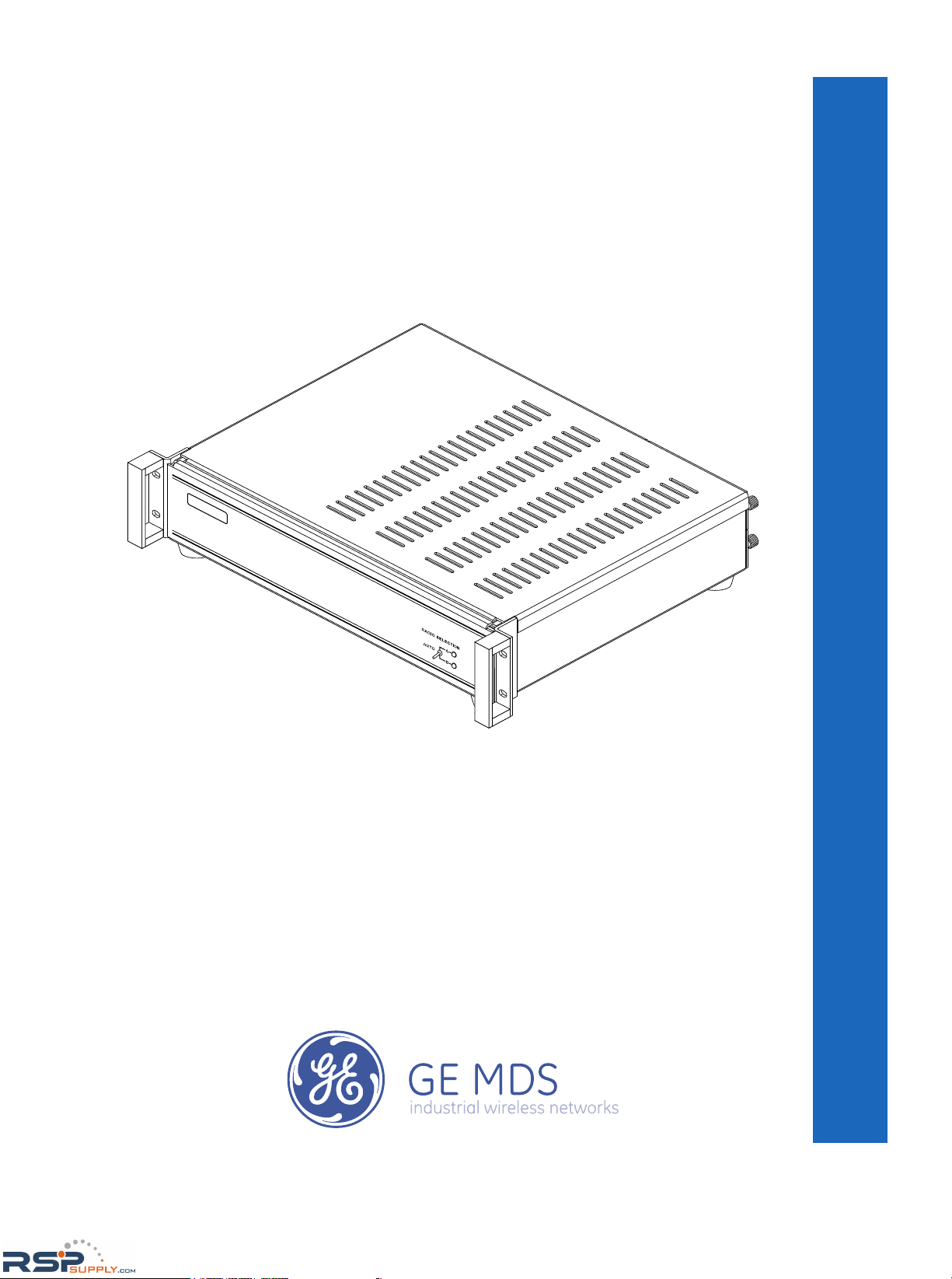
Protected Network Stations
Equipped with MDS iNET Series, EntraNET, or Mercury Transceivers
MDS P21/P22/P23
RSPSupply - 1-888-532-2706 - www.RSPSupply.com
http://www.RSPSupply.com/p-8464-MDS-P22-Redundant-Transceiver-Chasis-(Enet).aspx
Page 2

QUICK START GUIDE
Below are the basic steps for configuring a Protected Network Station. Detailed instructions are given in
“INSTALLATION” on Page 6.
1. Install transceivers (if not already present)
• Remove chassis cover.
• Remove the transceiver mounting plates.
• Mount the transceivers to the plates. Secure transceiver/plate assemblies to chassis. (Note that MDS
iNET/iNET-II and entraNET radios are stacked, but Mercury radios are installed side-by-side.)
• Connect internal cabling between transceivers and the Switchover Logic Board. (See “Internal
Cabling Arrangements” on Page 10.
2. Remove top cover plate and connect the internal back-up battery (if equipped). Re-install the
top cover.
• Units are shipped with the battery disconnected.
• Use care not to short the battery terminals.
• After the unit is powered up, allow several hours for the battery to fully charge.
3. Connect external wiring
• Connect chassis ground stud to facility’s Earth ground.
• Connect antenna feedline(s), data interface cabling, input power, and any alarm devices. (These
steps are explained with more detail in “External Connections” on Page 17.)
4. Program transceivers
• Programming can be performed with a PC terminal connected to the appropriate Data I/O connector
on the rear panel
• Consult transceiver manual(s) for programming details
5. Apply primary power
• Observe proper input voltage and polarity
• Verify that power supply has enough current capacity to power the chassis.
6. Select the active transceiver
• Set the front panel RADIO SELECTION Switch to A (Transceiver A, no auto switchover), B (Transceiver B, no auto switchover), or AUTO (automatic switchover)
7. Verify proper operation
• Observe LEDs on transceivers
•Refine directional antenna headings for maximum signal strength
RSPSupply - 1-888-532-2706 - www.RSPSupply.com
http://www.RSPSupply.com/p-8464-MDS-P22-Redundant-Transceiver-Chasis-(Enet).aspx
Page 3

05-4161A01, Rev. C P21/P22/P23 Protected Network Station i
TABLE OF CONTENTS
1.0 ABOUT THIS MANUAL ............................................................... 1
2.0 PRODUCT INFORMATION ......................................................... 1
2.1 Product Features ..............................................................................2
2.2 Chassis Radio Configurations ..........................................................3
2.3 Antenna Port Configurations ............................................................4
2.4 Items Supplied .................................................................................4
2.5 Model Configuration Codes ..............................................................5
3.0 INSTALLATION ............................................................................ 6
3.1 Installation Planning .........................................................................6
3.2 Installing Transceivers—MDS entraNET, iNET/iNET-II ...................... 7
3.3 Installing Transceivers—MDS Mercury .............................................9
3.4 Internal Cabling Arrangements ......................................................10
3.5 External Connections .....................................................................17
Safety Ground...............................................................................17
Station Antenna Connection(s)..................................................... 17
Data Connections ......................................................................... 18
Alarm Equipment Connections ..................................................... 19
Primary Power Connections ......................................................... 19
3.6 Mounting the Protected Network Station .......................................20
3.7 Initial Startup .................................................................................. 21
4.0 PROGRAMMING THE TRANSCEIVERS .................................. 23
4.1 Initial MDS iNET/iNET-II Programming and Setup ......................... 23
Redundancy Configuration Menus ...............................................23
“Mirrored Configuration” of Transceivers.......................................29
4.2 Initial MDS entraNET Programming and Setup .............................30
Redundancy Menu........................................................................30
4.3 “Mirrored Configuration” of Transceivers ........................................35
4.4 Initial MDS Mercury Programming and Setup ................................ 35
Redundancy Configuration (AP Only)...........................................35
5.0 TROUBLESHOOTING ............................................................... 36
6.0 TECHNICAL REFERENCE ....................................................... 37
6.1 Field-Replaceable Assemblies and Parts ......................................37
Replacing Power Supply Modules ................................................37
Replacing Other Assemblies ........................................................37
6.2 Specifications .................................................................................38
RSPSupply - 1-888-532-2706 - www.RSPSupply.com
http://www.RSPSupply.com/p-8464-MDS-P22-Redundant-Transceiver-Chasis-(Enet).aspx
Page 4
ii P21/P22/P23 Protected Network Station 05-4161A01, Rev. C
Copyright Notice
This Installation and Operation Guide and all software described herein
are protected by
copyright: 2007 GE MDS, LLC . All rights reserved.
GE MDS reserves its right to correct any errors and omissions in this
document.
Operational Safety Notices
The radio equipment described in this guide emits radio frequency
energy. Although the power level is low, the concentrated energy from
a directional antenna may pose a health hazard. Do not allow people to
come closer than 23 cm (9 inches) to the antenna when the transmitter
is operating in indoor or outdoor environments. More information on RF
exposure is on the Internet at www.fcc.gov/oet/info/documents/bulletins.
This manual is intended to guide a
professional installer to install,
operate and perform basic system maintenance on the described radio.
ESD Notice
To prevent malfunction or damage to this radio, which may be caused
by Electrostatic Discharge (ESD), the radio should be properly
grounded by connection to the ground stud on the rear panel. In addition,
the installer or operator should follow proper ESD precautions, such as
touching a grounded bare metal object to dissipate body charge, prior to
adjusting front panel controls or connecting or disconnecting cables on
the front or rear panels.
Environmental Information
The equipment that you purchased has required the extraction and use
of natural resources for its production. Improper disposal may contaminate the environment and present a health risk due to hazardous substances contained within. To avoid dissemination of these substances
into our environment, and to diminish the demand on natural resources,
we encourage you to use the appropriate recycling systems for disposal.
These systems will reuse or recycle most of the materials found in this
equipment in a sound way. Please contact the factory or your supplier
for more information on the proper disposal of this equipment.
Quality Policy Statement
We are committed to understanding and exceeding our customers’
needs and expectations.
• We appreciate our customers’ patronage. They are our business.
• We promise to serve them and anticipate their needs.
RF Exposure
RSPSupply - 1-888-532-2706 - www.RSPSupply.com
http://www.RSPSupply.com/p-8464-MDS-P22-Redundant-Transceiver-Chasis-(Enet).aspx
Page 5

iii P21/P22/P23 Protected Network Station 05-4161A01, Rev. C
• We are committed to providing solutions that are cost effective,
innovative and reliable, with consistently high levels of quality.
We are committed to the continuous improvement of all of our systems
and processes, to improve product quality and increase customer satisfaction.
ISO 9001 Registration
GE MDS adheres to this internationally accepted quality system standard.
Notice
While every reasonable effort has been made to ensure the accuracy of
this manual, product improvements may result in minor differences
between the manual and the product shipped to you. If you have additional questions or need an exact specification for a product, please contact our Customer Service Team using the information at the back of this
guide. In addition, manual updates can often be found on the GE MDS
web site at
www.GEmds.com .
RSPSupply - 1-888-532-2706 - www.RSPSupply.com
http://www.RSPSupply.com/p-8464-MDS-P22-Redundant-Transceiver-Chasis-(Enet).aspx
Page 6

iv P21/P22/P23 Protected Network Station 05-4161A01, Rev. C
RSPSupply - 1-888-532-2706 - www.RSPSupply.com
http://www.RSPSupply.com/p-8464-MDS-P22-Redundant-Transceiver-Chasis-(Enet).aspx
Page 7

05-4161A01, Rev. C P21/P22/P23 Protected Network Station 1
1.0 ABOUT THIS MANUAL
This guide provides:
• Instructions for installing the P21 (MDS iNET/iNET-II Series)
P22 (MDS entraNET), and P23 (MDS Mercury) Protected Network Stations, and configuring them for desired operation
• In-service operating instructions
• Instructions for installing or changing transceivers, power supplies and other assemblies in the chassis
• Troubleshooting information
This manual is a system-level guide to the Protected Network Station. It
does
not contain detailed information on the radio transceivers installed
within the chassis. Radio-specific information will be found in the
appropriate manual(s) supplied with the units installed in your system.
After installation, you may wish to keep this guide, the internal radio
documentation, and all other related information near the equipment for
future reference.
2.0 PRODUCT INFORMATION
The Protected Network Station (Figure 1) is a tabletop or rack-mount
unit designed to hold two GE MDS transceivers, two power supplies,
and a switchover logic board that automatically selects between transceiver A or B as the active transceiver. Manual transceiver selection
may also be made using a front panel switch.
NOTE:
When switchover occurs, a delay of approximately 30 seconds
occurs until the new radio initializes. It may take up to one
minute for the radio to re-establish a link with an associated
station.
Additionally, certain network devices may require up to 20
minutes to detect that the MAC address has changed for the IP
address of the radio. This does not affect the data-passing
ability of the radio—only the ability to conduct a console
management session.
RSPSupply - 1-888-532-2706 - www.RSPSupply.com
http://www.RSPSupply.com/p-8464-MDS-P22-Redundant-Transceiver-Chasis-(Enet).aspx
Page 8

2 P21/P22/P23 Protected Network Station 05-4161A01, Rev. C
Invisible place holder
Figure 1. Protected Network Station
With two transceivers and power supplies installed, the unit will continue to communicate even if a failure occurs in one of the transceivers
or its associated power supply. This capability is important in mission-critical applications where uninterrupted service is required.
At the time of publication, the following transceivers are supported by
the Protected Network Station:
• MDS iNET/iNET-II Series Access Point
• MDS iNET/iNET-II Series Dual Gateway Remote
• MDS iNET/iNET-II Series Ethernet Bridge Remote
• MDS iNET/iNET-II Series Serial Remote
• MDS entraNET (Access Point only)
• MDS Mercury (Access Point only)
The unit is equipped with alarm connections on the rear panel which
activate whenever the standby transceiver is put online. These are “dry”
(isolated) alarm contacts that may be connected to customer-supplied
external alarm equipment, such as a lamp or sounding device.
2.1 Product Features
The Protected Network Station provides:
• Fully-protected capability—Standard chassis contains two
transceivers and two power supplies. A provision for an
optional redundant antenna port is also available.
RSPSupply - 1-888-532-2706 - www.RSPSupply.com
http://www.RSPSupply.com/p-8464-MDS-P22-Redundant-Transceiver-Chasis-(Enet).aspx
Page 9

05-4161A01, Rev. C P21/P22/P23 Protected Network Station 3
• Automatic switchover to alternate transceiver if a failure occurs
in the primary unit or its power supply.
• Optional built-in battery backup for AC-powered units
• Rear panel alarm connections for customer-supplied alarm
equipment
• Tabletop or 19-inch rack mount installation
• Utilizes standard GE MDS transceivers inside
2.2 Chassis Radio Configurations
The chassis is available in the following transceiver configurations:
•
Two transceivers installed
This configuration provides an immediately usable Protected
Network Station for new installations.
•
One transceiver installed
This configuration allows customers to add an existing transceiver to the P21/22/23 chassis to create a Protected Network
Station.
•
No transceivers installed
This configuration allows customers to install two existing
transceivers in the empty chassis to create a Protected Network
Station.
NOTE:
Existing MDS iNET/iNET-II Series radios to be used in a
Protected Network Station must have firmware revision 5.1.0
or higher installed. (All firmware versions of iNET-II radios
meet this requirement.) If entraNET transceivers are used, they
must have firmware revision 2.3.7 or higher installed. Consult
the factory for firmware availability.
RSPSupply - 1-888-532-2706 - www.RSPSupply.com
http://www.RSPSupply.com/p-8464-MDS-P22-Redundant-Transceiver-Chasis-(Enet).aspx
Page 10

4 P21/P22/P23 Protected Network Station 05-4161A01, Rev. C
2.3 Antenna Port Configurations
The Protected Network Station can be configured with a single antenna,
or with two separate antennas for full redundancy to continue operation
if the primary antenna becomes damaged or is otherwise inoperative.
The following configurations are available:
•
Single antenna port
The port is automatically switched to the active transceiver by
an internal relay.
•
Two antenna ports
Each port is connected to one of the transceivers and to separate
station antennas.
2.4 Items Supplied
Figure 2 shows the contents of a typical Protected Network Station shipment.
Invisible place holder
Figure 2. Protected Network Station Typical Shipment
POWER CORD(S)
(AC type shown)
REDUNDANT
STATION
TRANSCEIVER
INSTRUCTION
MANUAL
P-21/22
INSTRUCTION
MANUAL
RSPSupply - 1-888-532-2706 - www.RSPSupply.com
http://www.RSPSupply.com/p-8464-MDS-P22-Redundant-Transceiver-Chasis-(Enet).aspx
Page 11

05-4161A01, Rev. C P21/P22/P23 Protected Network Station 5
2.5 Model Configuration Codes
The configuration details of the Protected Network Station (as shipped
from the factory) can be quickly determined from the model number
label attached to the outside of the chassis. Figure 3 shows the significance of the model number characters printed on the label.
Invisible place holder
Figure 3. Model Configuration Codes
PACKAGE
1 - 12V DC
2 - 24 V DC
3 - 48V DC
4 - 125V DC
A - 115/230V AC w/battery
B - 115/230V AC w/o battery
ANTENNA PORTS
1 - One
2 - Redundant
P2x
RSPSupply - 1-888-532-2706 - www.RSPSupply.com
http://www.RSPSupply.com/p-8464-MDS-P22-Redundant-Transceiver-Chasis-(Enet).aspx
Page 12

6 P21/P22/P23 Protected Network Station 05-4161A01, Rev. C
3.0 INSTALLATION
This section presents installation steps for:
1. I
nstallation Planning
2.
Installing transceiver(s) inside a chassis
This step may be skipped if transceivers are already installed.
3. Installing the Protected Network Station
Use these steps to connect external wiring and prepare the unit for
regular service.
4.
Configuring the Protected Network Station
This section describes how to set up the station for desired operation, including what events will trigger a switchover to the alternate
transceiver.
5.
Optimizing radio performance
This section offers tips for obtaining peak performance from your
Protected Network Station.
3.1 Installation Planning
Helpful advice for planning a radio system, including site and antenna
selection, can be found in the manual(s) supplied with your transceivers.
The Protected Network Station is typically installed at an Access Point
(AP) site to ensure uninterrupted communication with remote radios.
For iNET/iNET-II systems, it may also be used at one or more remote
sites in a network to increase reliability and protect against equipment
failures at these locations.
Figure 4 shows a typical installation arrangement.
The installation site should have adequate and stable primary power,
suitable access for cabling, and should not be subject to temperature
extremes or poor ventilation. The unit may be placed on a sturdy
tabletop or installed in a standard 19-inch rack cabinet.
RSPSupply - 1-888-532-2706 - www.RSPSupply.com
http://www.RSPSupply.com/p-8464-MDS-P22-Redundant-Transceiver-Chasis-(Enet).aspx
Page 13

05-4161A01, Rev. C P21/P22/P23 Protected Network Station 7
Invisible place holder
Figure 4. Typical P-Series Installation
3.2 Installing Transceivers—MDS entraNET,
iNET/iNET-II
(If not already installed)
The modular construction of the Protected Network Station makes it
easy to install transceivers. The only tool required is a Phillips screwdriver. If the transceivers were not installed at the factory, proceed with
the steps below for installation and to connect the internal cabling. Refer
to Figure 5 during these steps.
NOTE:
Before installing a transceiver in the chassis, make sure each
radio is operating properly as a standalone unit, and is
equipped with up-to-date firmware code. The latest revision of
firmware for most GE MDS products is available for download at www.GEmds.com.
1. Make sure the power is off.
2. Remove the top cover of the Protected Network Station by loosen-
ing the two screws at the rear panel.
3. If a backup battery is installed in the chassis, be sure it is discon-
nected from the battery control board.
4. Remove the transceiver mounting plates from the chassis by loosen-
ing the screws that secure them to the chassis.
5. Attach the lower mounting plate to the lower transceiver (Radio B)
using four screws. Attach the mounting plate and radio to the chassis.
STATION ANTENNA
LOW-LOSS FEEDLINE
PC, DATA
EQUIPMENT
OR LAN
TO DATA
INTERFACE CONN.
TO ANTENNA
CONNECTOR
PRIMARY
POWER CORD(S)
P2x PROTECTED
NETWORK STATION
(With transceivers installed)
RSPSupply - 1-888-532-2706 - www.RSPSupply.com
http://www.RSPSupply.com/p-8464-MDS-P22-Redundant-Transceiver-Chasis-(Enet).aspx
Page 14

8 P21/P22/P23 Protected Network Station 05-4161A01, Rev. C
6. Attach the upper mounting plate to the upper transceiver (Radio A)
using four screws. Place the radio/mounting plate over the top of
Radio B and attach the plate to the chassis.
7. Connect and secure the data interface, diagnostics and power cables
to the transceivers as shown in
Internal Cabling Arrangements on
Page 10
.
8. Connect the battery cable to the battery control board, if it has been
purchased and installed in the chassis. (See Figure 33 on Page 38.)
9. Re-install the top cover of the Protected Network Station and tighten
the side screws.
This completes the installation of transceivers in the chassis. Refer to
Section 3.5, External Connections to complete the installation.
Invisible place holder
Figure 5. Top View Showing Two Radios Installed
NOTE: The internal back-up battery (if equipped) is disconnected for
shipment from the factory. To enable back-up power, remove
the top cover of the chassis and connect the battery cable to the
battery control board. See Figure 33 on Page 38.
J11
COM1LAN PWR LINKCOM2
J16 J17
J13J2
J6
J8
J10J5
J14J3
J7
UPPER:
RADIO A
LOWER:
RADIO B
1
J12
J4
J18
J19
J1
J9
J15
COM2 LINKPWRLAN COM1
Battery
& Control PCB
RSPSupply - 1-888-532-2706 - www.RSPSupply.com
http://www.RSPSupply.com/p-8464-MDS-P22-Redundant-Transceiver-Chasis-(Enet).aspx
Page 15

05-4161A01, Rev. C P21/P22/P23 Protected Network Station 9
3.3 Installing Transceivers—MDS Mercury
(If not already installed)
The modular construction of the Protected Network Station makes it
easy to install transceivers. The only tool required is a Phillips screwdriver. If the transceivers were not installed at the factory, proceed with
the steps below for installation and to connect the internal cabling. Refer
to Figure 5 during these steps.
NOTE:
Before installing a transceiver in the chassis, make sure each
radio is operating properly as a standalone unit, and is
equipped with up-to-date firmware code. The latest revision of
firmware for most GE MDS products is available for download at www.GEmds.com.
1. Make sure the power is off.
2. Remove the top cover of the Protected Network Station by loosen-
ing the two screws at the rear panel.
3. If a backup battery is installed in the chassis, be sure it is discon-
nected from the battery control board.
4. Remove the transceiver mounting plates from the chassis by loosen-
ing the screws that secure them to the chassis.
5. Attach the Radio A mounting plate to the first transceiver using four
screws. Secure the mounting plate and radio to the chassis.
6. Attach the Radio B mounting plate to the second transceiver using
four screws. Secure the mounting plate and radio to the chassis.
7. Connect and secure the data interface, diagnostics and power cables
to the transceivers as shown in Internal Cabling Arrangements on
Page 10.
8. Connect the battery cable to the battery control board, if this option
has been purchased and installed in the chassis. (See Figure 33 on
Page 38.)
9. Re-install the top cover of the Protected Network Station and tighten
the side screws.
This completes the installation of Mercury transceivers in the chassis.
Refer to Section 3.5, External Connections to complete the installation.
RSPSupply - 1-888-532-2706 - www.RSPSupply.com
http://www.RSPSupply.com/p-8464-MDS-P22-Redundant-Transceiver-Chasis-(Enet).aspx
Page 16

10 P21/P22/P23 Protected Network Station 05-4161A01, Rev. C
Invisible place holder
Figure 6. Top View Showing Two Mercury Radios Installed
NOTE: The internal back-up battery (if equipped) is disconnected for
shipment from the factory. To enable back-up power, remove
the top cover of the chassis and connect the battery cable to the
battery control board. See Figure 33 on Page 38.
3.4 Internal Cabling Arrangements
The following figures illustrate the internal cabling arrangements for the
P21 (MDS iNET/iNET-II version), P22 (MDS entraNET version), and
P23 (MDS Mercury version). Refer to the drawing that shows your particular unit.
RSPSupply - 1-888-532-2706 - www.RSPSupply.com
http://www.RSPSupply.com/p-8464-MDS-P22-Redundant-Transceiver-Chasis-(Enet).aspx
Page 17

05-4161A01, Rev. C P21/P22/P23 Protected Network Station 11
Invisible place holder
Figure 7. P21 (MDS iNET/iNET-II Series) Internal Cabling—Lower
(B) Radio
J9
J9
J19
J19
J18
1
1
o
o
J15
J1
J11
J4
J12
1
1
<
<
<
<
<
<
<
<
<
<
J7
J14
J17
J3
J3
J14
J14
J5
J10
J8J6J2
J16
LOWER:
RADIO B
COM1LAN PWR LINKCOM2
Battery
& Control PCB
From Lower
Radio
To S/O-Logic
PCB Assy.
Cable Type
LAN J17 RJ-45
COM1 J2 DB-9 Male
COM2 J14 DB-9 Female
PWR J7 2-Conductor Phoenix
LINK (Antenna) J5 TNC Coaxial
RSPSupply - 1-888-532-2706 - www.RSPSupply.com
http://www.RSPSupply.com/p-8464-MDS-P22-Redundant-Transceiver-Chasis-(Enet).aspx
Page 18

12 P21/P22/P23 Protected Network Station 05-4161A01, Rev. C
Invisible place holder
Invisible place holder
Figure 8. P21 (MDS iNET/iNET-II Series) Internal Cabling—Upper
(A) Radio
COM2 LINKPWRLAN COM1
UPPER:
RADIO A
o
<
J12
J14
J14
J4
J11
J18
J3
J3
J19
J1
J9
J15
J7
J16 J17
J14J2J8
J10
J5
J6
J13J3
Battery
& Control PCB
From Upper
Radio
To S/O-Logic
PCB Assy.
Cable Type
LAN J16 RJ-45
COM1 J3 DB-9 Male
COM2 J13 DB-9 Female
PWR J6 2-Conductor Phoenix
LINK (Antenna) J10 TNC Coaxial
RSPSupply - 1-888-532-2706 - www.RSPSupply.com
http://www.RSPSupply.com/p-8464-MDS-P22-Redundant-Transceiver-Chasis-(Enet).aspx
Page 19

05-4161A01, Rev. C P21/P22/P23 Protected Network Station 13
Invisible place holder
Invisible place holder
Figure 9. P22 (MDS entraNET) Internal Cabling—Lower (B) Radio
J9
J9
J19
J19
J18
1
1
o
o
J15
J1
J11
J4
J12
1
1
<
<
<
<
<
<
<
<
<
<
J7
J14
J17
J5
J10
J8J6J2
J16
J14J3
LOWER:
RADIO B
COM1LAN PWR LINKCOM2
Battery
& Control PCB
From Lower
Radio
To S/O-Logic
PCB Assy.
Cable Type
LAN J17 RJ-45
COM1 J14 RJ-12
COM2 J2 RJ-45
PWR J7 2-Conductor Phoenix
LINK (Antenna) J5 TNC Coaxial
RSPSupply - 1-888-532-2706 - www.RSPSupply.com
http://www.RSPSupply.com/p-8464-MDS-P22-Redundant-Transceiver-Chasis-(Enet).aspx
Page 20

14 P21/P22/P23 Protected Network Station 05-4161A01, Rev. C
Invisible place holder
Invisible place holder
Figure 10. P22 (MDS entraNET) Internal Cabling—Upper (A) Radio
COM2 LINKPWRLAN COM1
UPPER:
RADIO A
o
<
J12
J14
J14
J4
J11
J18
J3
J3
J19
J1
J9
J15
J7
J16 J17
J14J2J8
J10
J5
J6
J13J3
Battery
& Control PCB
From Upper
Radio
To S/O-Logic
PCB Assy.
Cable Type
LAN J16 RJ-45
COM1 J13 RJ-12
COM2 J3 RJ-45
PWR J6 2-Conductor Phoenix
Link (Antenna) J10 TNC Coaxial
RSPSupply - 1-888-532-2706 - www.RSPSupply.com
http://www.RSPSupply.com/p-8464-MDS-P22-Redundant-Transceiver-Chasis-(Enet).aspx
Page 21

05-4161A01, Rev. C P21/P22/P23 Protected Network Station 15
Invisible place holder
Figure 11. P23 (MDS Mercury) Internal Cabling—Radio A
Radio Front Panel
Connector
Switchover Logic
PCB Assy.
Cable Type
PWR J6 2-Conductor
Phoenix
LAN J16 RJ-45
COM1 J3 DB-9 Male
GPS Antenna J20 SMA Coaxial
TX/RX1 J10 TNC Coaxial
RSPSupply - 1-888-532-2706 - www.RSPSupply.com
http://www.RSPSupply.com/p-8464-MDS-P22-Redundant-Transceiver-Chasis-(Enet).aspx
Page 22

16 P21/P22/P23 Protected Network Station 05-4161A01, Rev. C
Invisible place holder
Invisible place holder
Figure 12. P23 (MDS Mercury) Internal Cabling—Radio B
Radio Front Panel
Connector
Switchover Logic
PCB Assy.
Cable Type
PWR J7 2-Conductor
Phoenix
LAN J17 RJ-45
COM1 J2 DB-9 Male
GPS Antenna J22 SMA Coaxial
TX/RX1 J5 TNC Coaxial
RSPSupply - 1-888-532-2706 - www.RSPSupply.com
http://www.RSPSupply.com/p-8464-MDS-P22-Redundant-Transceiver-Chasis-(Enet).aspx
Page 23

05-4161A01, Rev. C P21/P22/P23 Protected Network Station 17
3.5 External Connections
All external connections are made at the unit’s rear panel. Refer to
Figure 13 for connector definitions. The text that follows provides additional detail for each connector.
Invisible place holder
Figure 13. Rear Panel of Protected Network Station
Safety Ground
Connect the rear panel ground stud to the facility’s safety ground (earth)
system.
Station Antenna Connection(s)
Connect the antenna feedline to the Type-N coaxial fitting provided on
the rear panel of the chassis. (Two such connections are required if the
unit is equipped with the Redundant Antenna Option.) If a directional
antenna is used, set its heading in the desired direction of transmission/reception.
GPS Antenna Connection—P23 only
Connect the GPS antenna feedline to the SMA-type coaxial connector
on the rear panel.
NOTE: It is highly recommended that lightning protection be properly
installed for all antenna systems.
POWER
ON/OFF
POWER
INPUT
ANTENNA / LINK
PORT (A+B)
ALARM
CONNECTIONS
REDUNDANT
ANTENNA / LINK
PORT (OPTIONAL)
GROUND STUD
(AC TYPE SHOWN)
POWER SUPPLY MODULES
LAN (ETHERNET)
CONNECTOR
J1 - DCE J15 - DTE
DATA I/O
INTERFACE
(P21 iNET COM2)
(P22 entraNET COM1)
(P23 Mercury—Unused)
DATA I/O
INTERFACE
(P21 iNET COM1)
(P22 entraNET COM2)
(P23 Mercury COM1)
GPS
ANTENNA*
* P23 Only
RSPSupply - 1-888-532-2706 - www.RSPSupply.com
http://www.RSPSupply.com/p-8464-MDS-P22-Redundant-Transceiver-Chasis-(Enet).aspx
Page 24

18 P21/P22/P23 Protected Network Station 05-4161A01, Rev. C
Data Connections
For the following connections, be sure to use only the required pins for
the application. Do not use a fully-wired (25 conductor) cable on the
DB-25 ports. Refer to Figure 14 for detailed views of the DB-25 interface connectors and Table 1 for DB-25 I/O connector functions.
a. Connect the facility’s Ethernet cable to the rear panel
LAN con-
nector.
b. Connect the facility’s serial data equipment to the appropriate
DB-25 Data I/O connector on the rear panel.
c. If you intend to program the transceivers, or perform local diag-
nostics with a PC, connect the computer to the appropriate console/terminal (DB-25) connector on the rear panel.
Invisible place holder
Figure 14. COM1 and COM2 Pinouts
(As viewed from outside the chassis)
Table 1. DB-25 Rear Panel Data Ports & Functions
Model & Internal
Transceivers
Left (Male) DCE:
Connected to Internal
Transceiver Port
Right (Female) DTE:
Connected to Internal
Transceiver Port
P21 (MDS iNET/iNET-II
Series)
COM1/DCE/Console COM2/DTE/Data
P22 (MDS entraNET) COM2/DCE/ Data COM1/DTE/Console
P23 (MDS Mercury) COM1/DCE/Console Unused
13
12
11
10
9
8
7
6
5
4
3
2
1
Data Carrier Detect (DCD)
Data Set Ready (DSR)
Clear-to-Send Output (CTS)
Request-to-Send Input (RTS)
Received Data (RXD)
Transmitted Data (TXD)
25
24
23
22
21
20
19
18
17
16
15
14
Description
Pin
No.
Pin
No.
Description
Data Terminal Ready (DTR)
Unused
Unused
Unused
Unused
Unused
Unused
Unused
Unused
Unused
Unused
Unused
Unused
Ground
Unused
Unused
Unused
Unused
Unused
RSPSupply - 1-888-532-2706 - www.RSPSupply.com
http://www.RSPSupply.com/p-8464-MDS-P22-Redundant-Transceiver-Chasis-(Enet).aspx
Page 25

05-4161A01, Rev. C P21/P22/P23 Protected Network Station 19
Alarm Equipment Connections
If alarm equipment (lamp, sounding device, etc.) is to be used with the
station, make the appropriate connections to the rear panel
ALARM ter-
minals.
Figure 15. Rear Panel Alarm Contacts
(For use when two radios are installed)
The ALARM terminals are “dry” (isolated) alarm contacts which close
(connect to the alarm common) when the Switchover Logic Board
detects that operation has switched to the secondary radio. Figure 15
shows the connection state in the absence of an alarm condition—the
right pin is Normally Open (NO) and the left pin is Normally Closed
(NC), with respect to the Common terminal.
The alarm contacts are rated for the following service: 0.5 Ampere at
125 Vac or 1.0 Ampere at 24 Vdc. The common terminal in the connector’s middle “floats” and is not connected to ground or any internal
power supply voltage source.
NOTE: The alarm functions are intended for use with a fully-popu-
lated and enabled chassis (i.e., two transceivers, two power
supplies, and both power supply switches set to ON). The front
panel switch should also be set to the AUTO position so that a
fault in the primary transceiver causes an automatic
switchover to the secondary transceiver. (It is this switchover
that applies power to the secondary radio, thereby causing the
alarm contacts to change state.)
Manual switchover to the secondary transceiver may also be
performed with the front panel switch, but it will immediately
cause the alarm contacts to change state, as a failure is assumed
in the primary radio.
Primary Power Connections
Connect input power to the power supply modules. See Figure 16
(AC units) and Figure 17 (DC units).
Alarm Common
Normally
Closed
Normally
Open
RSPSupply - 1-888-532-2706 - www.RSPSupply.com
http://www.RSPSupply.com/p-8464-MDS-P22-Redundant-Transceiver-Chasis-(Enet).aspx
Page 26

20 P21/P22/P23 Protected Network Station 05-4161A01, Rev. C
Invisible place holder
Figure 16. Input Power Connections (AC Units)
NOTE: The internal back-up battery (if installed) is disconnected for
shipment. To enable back-up power, remove the top cover of
the chassis and connect the battery cable to the battery control
board. See Figure 5 for details.
Invisible place holder
Figure 17. Input Power Connection (DC Units)
3.6 Mounting the Protected Network Station
The Protected Network Station can be placed on a sturdy tabletop, or
mounted in a 19 inch rack cabinet or equipment rack. Choose a
mounting location that provides easy access to the rear panel connectors
and an unobstructed view of the LED status indicators (through the rear
panel viewing slots). Figure 18 shows the dimensions of the Protected
Network Station.
POWER
ON/OFF
POWER INPUT
TRANSCEIVER B
GROUND STUD
POWER INPUT
TRANSCEIVER A
ON/OFF SWITCH
DC POWER INPUT
RSPSupply - 1-888-532-2706 - www.RSPSupply.com
http://www.RSPSupply.com/p-8464-MDS-P22-Redundant-Transceiver-Chasis-(Enet).aspx
Page 27

21 P21/P22/P23 Protected Network Station 05-4161A01, Rev. C
Invisible place holder
Figure 18. Mounting Dimensions
3.7 Initial Startup
In-service operation of the Protected Network Station is completely
automatic. Once the unit has been properly installed and configured,
operator actions are limited to observing the LED status indicators for
proper operation.
To prepare for full operation, make sure your Protected Network Station
is properly configured for the desired service. Basic configuration
instructions are provided in this manual for:
• MDS iNET/iNET-II Series transceivers, see “Initial
MDS iNET/iNET-II Programming and Setup” on page 23.
• MDS entraNET transceivers, see “Initial MDS entraNET Programming and Setup” on page 30.
• MDS Mercury transceivers, see “Initial MDS Mercury Programming and Setup” on page 35..
If all parameters are correctly set, operation of the Protected Station can
be started as follows:
1. Apply primary power.
2. Select the active transceiver by setting the front panel
RADIO SELEC-
TION switch to A, B or AUTO. (See Table 2 for an explanation of the
switch positions.)
19.05"
484 mm
RSPSupply - 1-888-532-2706 - www.RSPSupply.com
http://www.RSPSupply.com/p-8464-MDS-P22-Redundant-Transceiver-Chasis-(Enet).aspx
Page 28

22 P21/P22/P23 Protected Network Station 05-4161A01, Rev. C
Invisible place holder
Figure 19. Radio Select Switch
Invisible place holder
3. If desired, you may observe the transceiver LED status panel(s) for
the proper indications by removing the unit’s top cover plate. Refer
to the transceiver’s manual for an explanation of LED functions.
4. After the basic operation of the Protected Network Station has been
checked, you may wish to optimize transceiver performance using
some of the suggestions in the transceiver’s manual.
Table 2. Radio Selection Switch Positions
Switch
Position
Function
A Transceiver A is selected as the active unit. Switchover will not
occur if a failure occurs in Transceiver A or if the Remote
Switchover is invoked.
AUTO
(Normal/Default)
The most recently selected transceiver is active. If a failure
occurs with that unit, switchover automatically occurs to the
other transceiver.
Also, when the switch is in this position, the Remote Switchover
command can be invoked.
B Transceiver B is selected as the active unit. Switchover will not
occur if a failure occurs in Transceiver B or if the Remote
Switchover command is invoked.
RSPSupply - 1-888-532-2706 - www.RSPSupply.com
http://www.RSPSupply.com/p-8464-MDS-P22-Redundant-Transceiver-Chasis-(Enet).aspx
Page 29

23 P21/P22/P23 Protected Network Station 05-4161A01, Rev. C
4.0 PROGRAMMING THE
TRANSCEIVERS
This section presents menu settings for transceivers used in Protected
Network Stations. Only menus pertaining directly to protected network
operation are covered here. Please refer to the transceiver manual for all
other radio commands.
• For instructions on programming MDS iNET/iNET-II Series
transceivers, see “Initial MDS iNET/iNET-II Programming and
Setup” below.
• For instructions on programming MDS entraNET transceivers,
see “Initial MDS entraNET Programming and Setup” on Page
30.
• For instructions on programming MDS Mercury transceivers,
see “Initial MDS Mercury Programming and Setup” on
page 35.
4.1 Initial MDS iNET/iNET-II Programming and
Setup
This section presents menu settings for MDS iNET/iNET-II Series
transceivers used in P21 Protected Network Stations. Only menus pertaining directly to protected network operation are covered here. Please
refer to the transceiver manual for a complete list of radio commands.
NOTE: Radios used in a Protected Network Station chassis must have
firmware installed that supports redundant configuration.
MDS iNET/iNET-II Series transceivers must have revision
5.1.0 or higher installed. Consult the factory for firmware
availability.
NOTE: To ensure proper operation after a switchover, both trans-
ceivers in a Protected Network Station must have identical
configurations. After setting the configuration of one transceiver, refer to “Mirrored Configuration” of Transceivers on
Page 29 to transfer the same profile to the other radio.
Redundancy Configuration Menus
You enter the Redundancy Configuration menus by selecting this option
from the transceiver’s Main Menu (Figure 20). If the redundancy function is not already enabled, a password prompt appears. If you do not
have a password, contact your factory representative for assistance.
RSPSupply - 1-888-532-2706 - www.RSPSupply.com
http://www.RSPSupply.com/p-8464-MDS-P22-Redundant-Transceiver-Chasis-(Enet).aspx
Page 30

24 P21/P22/P23 Protected Network Station 05-4161A01, Rev. C
Invisible place holder
Figure 20. Transceiver’s Main Menu
Upon successful entry to the redundancy menus, the screen shown in
Figure 21 appears. This is the starting point for setting all parameters
related to redundancy switchover. The first menu item,
Redundancy Con-
figuration
, must be set to Enabled, for the switchover function to be active.
NOTE: When switchover occurs, a delay of approximately 30 seconds
occurs until the new radio initializes. It may take up to one
minute for the radio to re-establish a link with an associated
station.
Additionally, certain network devices may require up to 20
minutes to detect that the MAC address has changed for the IP
address of the radio. This does not affect the data-passing
ability of the radio—only the ability to conduct a console
management session.
Select this item for
redundancy configuration menus
RSPSupply - 1-888-532-2706 - www.RSPSupply.com
http://www.RSPSupply.com/p-8464-MDS-P22-Redundant-Transceiver-Chasis-(Enet).aspx
Page 31

25 P21/P22/P23 Protected Network Station 05-4161A01, Rev. C
Invisible place holder
Figure 21. Redundancy Menu (Top Level)
Select the letter of the item you wish to configure, and a sub-menu
appears with settable parameters. (Exception: Selecting the last item,
Force Switchover does not bring up a sub-menu. It initiates an immediate
change to the other transceiver.)
The following screens show the Redundancy sub-menus and provide
brief descriptions of their functionality.
Invisible place holder
Figure 22. Network Event Trigger Configuration
RSPSupply - 1-888-532-2706 - www.RSPSupply.com
http://www.RSPSupply.com/p-8464-MDS-P22-Redundant-Transceiver-Chasis-(Enet).aspx
Page 32

26 P21/P22/P23 Protected Network Station 05-4161A01, Rev. C
Figure 22 shows a list of Network Events that can trigger a switchover.
When
ENABLED is selected in the menu, the event will trigger a
switchover. When
DISABLED is selected, no switchover occurs for that
event. An explanation of menu items is provided below:
Invisible place holder
Figure 23. Radio Event Trigger Configuration
Figure 23 above shows the list of Radio Events that can trigger a
switchover. When the status is
ENABLED, the event will trigger a
switchover. When the status is
DISABLED, no switchover occurs for that
event. An explanation of menu items is provided below:
AP Ethernet Link
Disconnected
The AP’s Ethernet cable is disconnected, damaged, or
the AP hasn’t been able to poll a specified address.
For this event to occur, the following values must be
configured properly on the Redundancy Configuration
Options menu:
Ethernet Link H/W Watch enable/disable
Ethernet Link Poll Address X.X.X.X
Network Interface Error There is a problem with the network interface.
MAC Decryption Failed Caused by mismatched encryption phrases. When this
occurs, the units will associate, but data will not be
passing in both directions.
RSPSupply - 1-888-532-2706 - www.RSPSupply.com
http://www.RSPSupply.com/p-8464-MDS-P22-Redundant-Transceiver-Chasis-(Enet).aspx
Page 33

27 P21/P22/P23 Protected Network Station 05-4161A01, Rev. C
Country/SkipZone Mismatch The unit is not receiving the correct frequency
hopping format.
Lack of Associated Remotes
Exceeded Threshold
The Access Point fails to have any associated
remotes for specified period of time.
For this event to occur properly, the following
value must be configured in the Redundancy
Configuration Options menu:
Lack of Remotes for x (seconds)
For Remotes (instead of above):
Loss of Associated AP
Exceeded Threshold
The Remote fails to have an associated AP for
specified period of time.
For proper detection, the following value must
be configured in the Redundancy
Configuration Options menu:
Loss of Access Point for x (seconds)
Packet Receive Errors
Exceeded Threshold
The rate of Packet Receive Errors exceeded
the defined threshold
For proper detection, the following values must
be configured in the Redundancy
Configuration Options menu. (These configure
the Maximum number or packet receive errors
within a specific period of time before a
redundancy switchover occurs.):
Maximum Receive Errors x
Receive Error Count Interval x (seconds)
Packet Retry Errors Exceeded
Threshold
The rate of Packet Send Errors exceeded the
defined threshold
For proper detection, the following values must
be configured in the Redundancy
Configuration Options menu. (These configure
the Maximum number or packet retry errors
within a specific period of time before a
redundancy switchover occurs.):
Maximum Retry Errors x
Retry Error Count Interval x (seconds)
RSPSupply - 1-888-532-2706 - www.RSPSupply.com
http://www.RSPSupply.com/p-8464-MDS-P22-Redundant-Transceiver-Chasis-(Enet).aspx
Page 34

28 P21/P22/P23 Protected Network Station 05-4161A01, Rev. C
Invisible place holder
Figure 24. Hardware Event Trigger Configuration
Figure 24 above shows the list of Hardware Events that will trigger a
switchover. When
ENABLED is selected, the event triggers a switchover.
When set to
DISABLED, no switchover occurs for that event. An explana-
tion of menu items is provided below:
MAC communication Failed The main CPU is unable to communicate to the
MAC.
FPGA communication Failed The main CPU is unable to communicate to the
FPGA.
ADC output Railed The Analog to Digital Converter is railed.
Frequency Not Calibrated The unit’s Frequency Adjustment Algorithm is
not properly calibrated
Power Not Calibrated The unit’s Power Adjustment Algorithm is not
properly calibrated
Flash Test Failed There is a problem with the Flash memory
PLL Not locked The Phase Lock Loop was not locked
RF Power Control Saturated
High
There is a hardware defect that is causing the
Power Control Loop to fail.
RSPSupply - 1-888-532-2706 - www.RSPSupply.com
http://www.RSPSupply.com/p-8464-MDS-P22-Redundant-Transceiver-Chasis-(Enet).aspx
Page 35

29 P21/P22/P23 Protected Network Station 05-4161A01, Rev. C
Invisible place holder
Figure 25. Redundancy Configuration Options
The Redundancy Configuration Options screen (Figure 25) allows you
to set the threshold limits or behavior for many redundancy-triggering
events. To configure an option, simply select the letter of the menu item
and follow the instructions at the bottom of the screen.
“Mirrored Configuration” of Transceivers
To ensure proper operation after a switchover, it is important that both
transceivers in a Protected Network Station have the identical configuration profile. This can be accomplished using a configuration file as
follows:
1. Install transceivers in the chassis as described earlier. Apply power
to the Protected Network Station.
2. Set the front panel
RADIO SELECTION switch to “A”.
RF Power Control Saturated Low There is a hardware defect that is causing the
Power Control Loop to fail.
Initialization Error The software failed to initialize properly.
Additional Menu Item for Remotes:
SNR Below Threshold
The Signal to Noise ratio is below the
user-defined threshold.
For proper detection, the following value must
be configured in the Redundancy
Configuration Options menu on the Remote:
SNR Threshold x
Additional Menu Item for Remotes:
RSSI Below Threshold
The Receiver Signal Strength Indication is
below the user-defined threshold.
For proper detection, the following value must
be configured in the Redundancy
Configuration Options menu on the Remote:
RSSI Threshold x (dBm)
RSPSupply - 1-888-532-2706 - www.RSPSupply.com
http://www.RSPSupply.com/p-8464-MDS-P22-Redundant-Transceiver-Chasis-(Enet).aspx
Page 36

30 P21/P22/P23 Protected Network Station 05-4161A01, Rev. C
3. Configure Radio A (upper unit) as appropriate. Save the configura-
tion file to a TFTP server as described in the transceiver manual.
4. Set the front panel
RADIO SELECTION switch to “B”. Download the
saved configuration file into Radio B (lower unit).
5. This completes the configuration procedure. Set the front panel
switch to
AUTO, re-install the top cover, and the unit is ready for ser-
vice.
4.2 Initial MDS entraNET Programming and Setup
This section presents menu settings for MDS entraNET transceivers
used in P22 Protected Network Stations. Only menus pertaining directly
to protected network operation are covered here. Please refer to the
transceiver manual (Part No. 05-4055A01) for a complete list of radio
commands and other operation details.
(For instructions on programming MDS iNET/iNET-II Series transceivers, see “Initial MDS iNET/iNET-II Programming and Setup” on
Page 23.)
NOTE: MDS entraNET radios used in a Protected Network Station
must have firmware revision 2.3.7 or higher installed. Consult
the factory for firmware availability.
Redundancy Menu
Redundancy is available only at the AP. The Redundancy Menu is used
in protected installations where a backup transceiver can be immediately placed online should a primary unit fail. This protects against
“single point of failure” scenarios. The Redundancy menu contains
selections and settings that are used to manage redundancy functions.
NOTE: The chassis uses a Switchover Logic Board (Part No.
03-6061Axx). This board is similar in appearance to the one
used in P20 configurations, but they are not interchangeable.
Consult factory for assistance with replacement PCBs.
RSPSupply - 1-888-532-2706 - www.RSPSupply.com
http://www.RSPSupply.com/p-8464-MDS-P22-Redundant-Transceiver-Chasis-(Enet).aspx
Page 37

31 P21/P22/P23 Protected Network Station 05-4161A01, Rev. C
Invisible place holder
Figure 26. Redundancy Menu
• Redundancy Configuration—This selection is used to enable or
disable redundancy operation. When the supervisory board
detects an alarm condition, the currently selected transceiver is
disabled, and the backup transceiver comes online.
[
enabled, disabled; disabled]
•
Network Event Triggers—This selection presents a submenu (see
Figure 27) with Ethernet (network) related alarm conditions.
•
Hardware Event Triggers—This selection presents a submenu (see
Figure 28) with parameters related to local alarm conditions.
•
Redundancy Configuration Options—This selection presents a sub-
menu (see Figure 29) for duration settings related to network
events. (e.g., if a PING attempt fails after xx minutes, a contingency action will be taken, such as the radio switching from the
active to standby unit.)
•
Force Switchover—This selection invokes an immediate switcho-
ver from the active to the standby unit.
RSPSupply - 1-888-532-2706 - www.RSPSupply.com
http://www.RSPSupply.com/p-8464-MDS-P22-Redundant-Transceiver-Chasis-(Enet).aspx
Page 38

32 P21/P22/P23 Protected Network Station 05-4161A01, Rev. C
Invisible place holder
Figure 27. Network Event Triggers Menu
• Network Interface Error—This selection is used to enable or disable redundancy switchover on the occurrence of a Network
Interface Error. [
enabled, disabled; enabled]
Invisible place holder
Figure 28. Hardware Event Triggers Menu
RSPSupply - 1-888-532-2706 - www.RSPSupply.com
http://www.RSPSupply.com/p-8464-MDS-P22-Redundant-Transceiver-Chasis-(Enet).aspx
Page 39

05-4161A01, Rev. C P21/P22/P23 Protected Network Station 33
• Frequency Not Calibrated—This selection is used to enable or disable redundancy switchover if a frequency calibration error
occurs. If this error occurs, the radio will require factory service.
[
enabled, disabled; disabled]
•
Power Not Calibrated—This selection is used to enable or disable
redundancy switchover if an RF power calibration error occurs.
If an error occurs, the radio will require factory service.
[
enabled, disabled; disabled]
Invisible place holder
Figure 29. Redundancy Configuration Options Menu
• Lack of Associated Remotes Exceeded Threshold—This selection
brings up another screen (Figure 30) where you can specify the
duration of time that a redundant AP waits before considering
itself to be malfunctioning. (A system must have at least one
associated remote to be functional.)
•
Packet Receive Errors Exceeded Threshold—This selection brings
up another screen (Figure 31) where you can specify the number
of packet errors that must be exceeded in a given time frame
before a redundant AP considers itself to be malfunctioning.
RSPSupply - 1-888-532-2706 - www.RSPSupply.com
http://www.RSPSupply.com/p-8464-MDS-P22-Redundant-Transceiver-Chasis-(Enet).aspx
Page 40

34 P21/P22/P23 Protected Network Station 05-4161A01, Rev. C
Invisible place holder
Figure 30. Lack of Associated Remotes Exceeded Threshold Menu
• Lack of Remotes for—the duration of time that a redundant AP
waits (in seconds) before considering itself to be malfunctioning.
Invisible place holder
Figure 31. Packet Rx Errors Exceeded Threshold Menu
This screen contains two settings relating to Packet Receive Errors. One
setting sets the number of missed packets, and the other sets a time
interval after which an error is declared. The settings work together, and
both criteria must be met before a redundancy switchover occurs.
These configuration settings are intended for data-intensive applications
and must be customized for your specific application.
RSPSupply - 1-888-532-2706 - www.RSPSupply.com
http://www.RSPSupply.com/p-8464-MDS-P22-Redundant-Transceiver-Chasis-(Enet).aspx
Page 41

05-4161A01, Rev. C P21/P22/P23 Protected Network Station 35
• Maximum Receive Errors—Here, you specify the number of packet
errors that must be exceeded before a redundant AP is reported
as malfunctioning. This setting works in conjunction with the
Interval setting below. [
0-1000; 300]
•
Receive Error Count Interval—This field is used for entering a time
interval that dictates the duration (in seconds) that works in conjunction with the Maximum Receive Errors above.
[
time interval; 300 seconds]
4.3 “Mirrored Configuration” of Transceivers
To ensure proper operation after a switchover, it is important that both
MDS entraNET transceivers in a P22 Protected Network Station have
the identical operational configuration profiles. This can be accomplished using a configuration file of one transceiver to configure the
second transceiver mounted in the protected chassis. The follows steps
outline the configuration process. Please review the use of a terminal
and TFTP programs in the radio transceiver’s manual before starting the
procedure.
1. Install transceivers in the chassis as described earlier. Apply power
to the Protected Network Station.
2. Set the front panel
RADIO SELECTION switch to “A”.
3. Configure Radio A (upper unit) as appropriate. Save the configuration file to a TFTP server as described in the transceiver manual.
4. Set the front panel
RADIO SELECTION switch to “B”. Download the
saved configuration file into Radio B (lower unit).
5. This completes the configuration procedure. Set the front panel
switch to
AUTO, re-install the top cover, and the unit is ready for ser-
vice.
4.4 Initial MDS Mercury Programming and Setup
Redundancy Configuration (AP Only)
Only AP Mercury radios may be used in a P23 chassis, and a second,
properly configured radio must be present.
Mercury’s Redundancy Configuration Menu (Figure 32) is where you
enable/disable redundancy operation and define the triggers that will
cause a switchover to the alternate unit.
RSPSupply - 1-888-532-2706 - www.RSPSupply.com
http://www.RSPSupply.com/p-8464-MDS-P22-Redundant-Transceiver-Chasis-(Enet).aspx
Page 42

36 P21/P22/P23 Protected Network Station 05-4161A01, Rev. C
Invisible place holder
Figure 32. Redundancy Configuration Menu (AP Only)
Below are brief descriptions of the menu items available on the Redundancy Configuration Menu. Refer to the Mercury Reference Manual
(Part No. 05-4446A01) for complete details on this menu and its associated submenus.
•
Redundancy Configuration—Enable/disable redundancy switcho-
ver for an AP. [
enabled, disabled; disabled]
• Network Event Triggers—This selection brings up a submenu
where you can set/view the trigger status for Network Events.
•
Radio Event Triggers—This selection presents a submenu where
you can set/view the trigger status for Radio Events, such as a
loss of associated Remotes or excessive packet errors.
•
Hardware Event Triggers—This selection brings up a submenu
where you can set/view the trigger status for initialization/hardware errors.
•
Redundancy Configuration Options—Presents a submenu where
you can set the threshold criteria for declaring an error event.
•
Force Switchover—Selecting this option forces a manual (user
initiated) switchover to the backup AP. The “challenge question”
Are you sure? (y/n) is presented to avoid an unintended
switchover. To invoke the change, press the letter
y followed by
the Enter key.
5.0 TROUBLESHOOTING
The radio LED status indicators are an important troubleshooting tool
and should be checked whenever a problem is suspected. Consult the
transceiver manual for a discussion of LED functions.
RSPSupply - 1-888-532-2706 - www.RSPSupply.com
http://www.RSPSupply.com/p-8464-MDS-P22-Redundant-Transceiver-Chasis-(Enet).aspx
Page 43

05-4161A01, Rev. C P21/P22/P23 Protected Network Station 37
When an alarm condition exists, the transceiver creates an alarm code or
message that can be read on a PC terminal connected to the rear panel
DIAGNOSTICS port. This information can be helpful in resolving many
system difficulties. Consult the transceiver manual for a discussion of
alarm messages and corrective action.
6.0 TECHNICAL REFERENCE
6.1 Field-Replaceable Assemblies and Parts
Table 3 lists field-replaceable internal assemblies and parts available to
implement repairs. Contact the factory for price and availability.
Replacing Power Supply Modules
Power supply modules are held in place with two knurled thumbscrews
at the rear of the chassis. To remove a power supply, loosen the two captive screws and slide the unit straight out. (There are no cables to disconnect, as the modules are fitted with in-line connectors.)
To re-install the modules, make sure that the slides are properly aligned
with the guide slots on the chassis, and push straight in. Tighten the
thumbscrews to secure the assembly.
Replacing Other Assemblies
The Switchover Logic Board and the front panel Indicator Board
(03-3307A01) are held in place with Phillips screws. To remove these
assemblies, disconnect all connectors from the board and remove the
mounting screws. The boards can then be removed from the chassis.
Table 3. Field Replaceable Assemblies and Parts
Assembly Part Number
Power Supply Module 03-1143A12 (115/230 Vac)
03-2613A02 (18-36 Vdc)
03-2613A03 (36-75 Vdc)
03-2613A04 (10.5-16 Vdc)
Switchover Logic Board
(P21/P22)
03-6061A01
Switchover Logic Board
(P23)
03-6061A03
Battery Control Board 03-3362A01
Indicator Board 03-3307A01
Backup Battery (1.2 Ah) 28-1575A03
Top Cover Plate 82-3365A01
RSPSupply - 1-888-532-2706 - www.RSPSupply.com
http://www.RSPSupply.com/p-8464-MDS-P22-Redundant-Transceiver-Chasis-(Enet).aspx
Page 44

38 P21/P22/P23 Protected Network Station 05-4161A01, Rev. C
The Backup Battery (28-1575A03) and Battery Control Board
(03-3362A01), if present, can be removed by loosening the bracket that
holds it to the chassis and disconnecting its push-on terminals. Use care
not to short the battery terminals during removal. Figure 33 shows the
battery, control board and associated interface cables.
Invisible place holder
Figure 33. Backup Battery and Control Board Assemblies
6.2 Specifications
Physical
Case: Aluminum (rack mountable 2U)
Dimensions: 8.9 cm (3.5”) high
48.3 cm (19.0”) wide
35.6 cm (14.0”) deep
Weight: 5.74 kg (12.65 lbs.) w/o transceivers
Approx. 1 kg (2.2 lbs.) additional for each transceiver
Environmental
Temperature Range: 0°C to +50°C (32° to 122° F)
Humidity: 95% at 40°C (104° F), non-condensing
Power Supplies
115/230 Vac with battery backup
12 Vdc (10.5-15 Vdc Operating Range)
24 Vdc (18-36 Vdc Operating Range)
48 Vdc (36-72 Vdc Operating Range)
Connect to J12 on the
Connect to J1 on
Battery Control PCB
Battery (L) & Battery Control Board (R)
Switchover Logic PCB
RSPSupply - 1-888-532-2706 - www.RSPSupply.com
http://www.RSPSupply.com/p-8464-MDS-P22-Redundant-Transceiver-Chasis-(Enet).aspx
Page 45

05-4161A01, Rev. C P21/P22/P23 Protected Network Station 39
General
Frequency Range: Dependent on transceiver(s) installed. See trans-
ceiver manual.
Data Interface: IP/Ethernet, Serial (RS-232). Provided by two rear
panel DB-25 connectors (DCE and DTE)
Diagnostic Interface: Serial (RS-232), Telnet, or Web browser. Provided
by a rear panel DB-25 connector.
Alarm Output: Dry (isolated) contacts for controlling an alarm
device upon primary power failure or transceiver
switchover.
Transceiver Ordering Options
Transceiver Complement: 1, 2 or no transceivers mounted in chassis
RSPSupply - 1-888-532-2706 - www.RSPSupply.com
http://www.RSPSupply.com/p-8464-MDS-P22-Redundant-Transceiver-Chasis-(Enet).aspx
Page 46

40 P21/P22/P23 Protected Network Station 05-4161A01, Rev. C
RSPSupply - 1-888-532-2706 - www.RSPSupply.com
http://www.RSPSupply.com/p-8464-MDS-P22-Redundant-Transceiver-Chasis-(Enet).aspx
Page 47

05-4161A01, Rev. C P21/P22/P23 Protected Network Station I-1
A
Antenna
port configurations 4
B
Battery Control Board, replacing 37
C
Configurations
antenna port 4
chassis 3
D
Dimensions, mounting 21
F
Features 2
I
Illustrations
model configuration codes 5
Protected Network Chassis chassis 2
Protected Network Station chassis, internal view 8, 10
Protected Network Station installation 7
Protected Network Station mounting dimensions 21
Protected Network Station rear panel 17
Protected Network Station shipment contents 4
radio selection switch 22
Indicator Board, replacing 37
Installation 6–21
initial start-up 21
mounting chassis 20
planning 6
programming transceivers 23, 30
transceivers 7, 9
M
Model configuration codes, illustrated 5
P
Power supply
replacing module 37
Procedures
initial start-up 21
installing transceivers 7, 9
mounting Protected Network Station chassis 20
programming transceivers 23, 30
replacing parts (Technical Reference) 37
troubleshooting 36
Protected Network Station
typical installation 7
Protected Network Station chassis
configurations 3
features 2
how to mount 20
illustrated 2
internal view, illustrated 8, 10
rear panel, illustrated 17
replacement parts for 37
shipment contents, illustrated 4
R
Radio selection switch, illustrated 22
Rear panel
connections, illustrated 17
Replacement parts 37
replacing 37
S
Start-up procedures 21
Switchover Logic Board, replacing 37
T
Tables
radio selection switch positions 22
Technical reference (assembly replacement) 37
Transceivers
initial programming 23, 30
installation of 7, 9
Troubleshooting 36
RSPSupply - 1-888-532-2706 - www.RSPSupply.com
http://www.RSPSupply.com/p-8464-MDS-P22-Redundant-Transceiver-Chasis-(Enet).aspx
Page 48

I-2 P21/P22/P23 Protected Network Station 05-4161A01, Rev. C
RSPSupply - 1-888-532-2706 - www.RSPSupply.com
http://www.RSPSupply.com/p-8464-MDS-P22-Redundant-Transceiver-Chasis-(Enet).aspx
Page 49

IN CASE OF DIFFICULTY...
GE MDS products are designed for long life and trouble-free operation. However, this equipment, as with
all electronic equipment, may have an occasional component failure. The following information will assist
you in the event that servicing becomes necessary.
TECHNICAL ASSISTANCE
Technical assistance for GE MDS products is available from our Technical Support Department during
business hours (8:00 A.M.—5:30 P.M. Eastern Time). When calling, please give the complete model
number of the radio, along with a description of the trouble/symptom(s) that you are experiencing. In many
cases, problems can be resolved over the telephone, without the need for returning the unit to the factory.
Please use one of the following means for product assistance:
Phone: 585 241-5510 E-Mail: TechSupport@GEmds.com
FAX: 585 242-8369 Web: www.GEmds.com
FACTORY SERVICE
Component level repair of this equipment is not recommended in the field. Many components are installed
using surface mount technology, which requires specialized training and equipment for proper servicing.
For this reason, the equipment should be returned to the factory for any PC board repairs. The factory is
best equipped to diagnose, repair and align your radio to its proper operating specifications.
If return of the equipment is necessary, you must obtain a Service Request Order (SRO) number. This
number helps expedite the repair so that the equipment can be repaired and returned to you as quickly as
possible. Please be sure to include the SRO number on the outside of the shipping box, and on any correspondence relating to the repair. No equipment will be accepted for repair without an SRO number.
SRO numbers are issued online at www.GEmds.com/support/product/sro/. Your number will be issued
immediately after the required information is entered. Please be sure to have the model number(s), serial
number(s), detailed reason for return, ship to address, bill to address, and contact name, phone number,
and fax number available when requesting an SRO number. A purchase order number or pre-payment will
be required for any units that are out of warranty, or for product conversion.
If you prefer, you may contact our Product Services department to obtain an SRO number:
Phone Number: 585-241-5540
Fax Number: 585-242-8400
E-mail Address: productservices@GEmds.com
The radio must be properly packed for return to the factory. The original shipping container and packaging
materials should be used whenever possible. All factory returns should be addressed to:
GE MDS, LLC
Product Services Department
(SRO No. XXXX)
175 Science Parkway
Rochester, NY 14620 USA
When repairs have been completed, the equipment will be returned to you by the same shipping method
used to send it to the factory. Please specify if you wish to make different shipping arrangements. To
inquire about an in-process repair, you may contact our Product Services Group using the telephone, Fax,
or E-mail information given above.
RSPSupply - 1-888-532-2706 - www.RSPSupply.com
http://www.RSPSupply.com/p-8464-MDS-P22-Redundant-Transceiver-Chasis-(Enet).aspx
Page 50

GE MDS, LLC
Rochester, NY 14620
General Business: +1 585 242-9600
FAX: +1 585 242-9620
Web: www.GEmds.com
175 Science Parkway
RSPSupply - 1-888-532-2706 - www.RSPSupply.com
http://www.RSPSupply.com/p-8464-MDS-P22-Redundant-Transceiver-Chasis-(Enet).aspx
 Loading...