

Page 1

Installation & Operation Guide
Supporting Phase 1 Units
MDS 05-4819A01, Rev. 08
MAY 2010
MDS LCT 450
Tri-Mode Data Transceiver
Page 2

OPERATIONAL & SAFETY NOTICES
Concentrated energy from a directional antenna may pose a health
hazard to humans. Do not allow people to come closer to the antenna
than the distances listed in the table below when the transmitter is
operating. More information on RF exposure can be found online at
the following website:
www.fcc.gov/oet/info/documents/bulletins
.
Above data based on a 30-watt RF output level with a 100% duty cycle.
FCC Part 15 Notice
The transceiver is approved under Part 15 of the FCC Rules. Operation is subject to the following two conditions: (1) this device may not cause harmful interference, and (2) this device
must accept any interference received, including interference that may cause undesired operation. Any unauthorized modification or changes to this device without the express approval of
Microwave Data Systems may void the user’s authority to operate this device. Furthermore,
this device is intended to be used only when installed in accordance with the instructions outlined in this manual. Failure to comply with these instructions may void the user’s authority to
operate this device.
Antenna Gain vs. Recommended Safety Distance
Device complies with Power Density requirements at 20 cm separation: No
Required separation distance for 5 dBi antenna (in meters): 1.6
Required separation distance for 10 dBi antenna (in meters): 2.8
Required separation distance for 16.5 dBi antenna (in meters): 6.0
RF Exposure
Page 3

05-4819A01, Rev. 08 LCT 450 Installation/Operation Guide
1
INTRODUCTION
This guide presents installation and operating instructions for the
MDS LCT 450 Series wireless transceiver.
The transceiver (Figure 1) is designed to operate in Railroad Distributed Power applications. It is software-configurable to provide flexible operation in a variety of applications using one hardware
platform. It employs microprocessor control and Digital Signal Processing (DSP) technology to provide robust communications even
under adverse conditions.
Figure 1. Data Transceiver
NOTE:
Some features may not be available on all units, based on the
options purchased and the applicable regulatory constraints
for the region in which the radio will operate.
Front Panel Connectors
Figure 2 and Figure 3 show the interface connectors and indicators on
the transceiver’s front and rear panels. These items are referenced in
the installation steps given later in this guide.
Page 4

2 LCT 450 Installation/Operation Guide 05-4819A01, Rev. 08
Invisible place holder
Figure 2. Antenna & DC Power Connectors
Invisible place holder
Figure 3. Data Interface Connectors & LED Status Panel
DC Power Input
13.6 Vdc +/-15%
Antenna Connector
(UHF)
Power Connector:
Tyco/AMP Electronics 172129-1
LED Indicator Panel
P1 Control Interface Connect
(DB-25)
PWR
DCD
TXD
RXD
P2 Programming & Diagnostic
(DB-9)
Page 5

05-4819A01, Rev. 08 LCT 450 Installation/Operation Guide
3
INSTALLATION
There are three main requirements for installing the transceiver as follows:
• Adequate and stable primary power
• An efficient and properly installed antenna system
• Correct data connections between the transceiver and the data
equipment.
Figure 4 shows a typical station arrangement. This is followed by
step-by-step procedures for installing the transceiver and making front
and rear panel connections.
Figure 4. Typical Station Arrangement
INTEGRATED PROCESSING
MODULE (IPM)
ANTENNA
SYSTEM
LOW-LOSS
COAXIAL CABLE
(50 Ohm)
RADIO
TRANSCEIVER
PL-259 UHF
CONNECTOR
DB-25M
CONNECTOR
Antenna Connector
DC POWER CABLE
Negative Ground
13.6 Vdc +/-15%
Page 6
4 LCT 450 Installation/Operation Guide 05-4819A01, Rev. 08
Installation Steps
Below are the basic steps for installing the transceiver. Refer to
Figure 4 as necessary when making cable connections.
1.
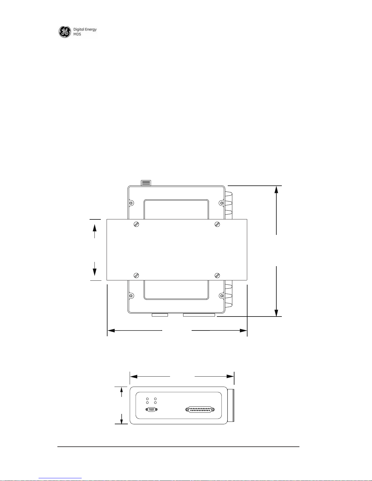
Mount the transceiver to a stable surface using the U-shaped
bracket provided. Begin by attaching the radio’s mounting bracket
to the bottom of the transceiver case (if not already attached) using
the four 6-32 x 1/4 inch (6 mm) screws supplied. Figure 5 shows
the transceiver mounting dimensions with bracket attached.
NOTE:
To prevent moisture from entering the radio, do not mount the
case with the cable connectors pointing up. Also, dress all
cables to prevent moisture from running along the cables and
into the radio.
Invisible place holder
Figure 5. Transceiver Mounting Bracket Dimensions
6.86"
3.25"
83 mm
2.0"
51 mm
5.63"
143 mm
174.24 mm
177.80 mm
7.00"
U-Shaped Bracket
(Part No. 821753A14)
Page 7

05-4819A01, Rev. 08 LCT 450 Installation/Operation Guide
5
Using screws longer than 1/4 inch (6 mm) to attach the
bracket to the radio may damage the internal PC board.
Use only the supplied screws.
2.
Install the antenna and feedline for the station. The antenna
used with the transceiver must be designed to operate in the
radio’s frequency band, and be mounted in a location that provides a clear path to the other associated station(s). Use low loss
coaxial feedline and keep the cable as short as possible.
3.
Connect the data equipment to the
DATA INTERFACE
connector. Check P1 CONTROL INTERFACE on Page 24 for pin wiring
details.
NOTE:
The radio’s
P2
port is used for entering configuration
commands and reprogramming the radio’s firmware.
4.
Connect primary power to the transceiver. Power applied must
be 13.6 Vdc (+/- 15%) and capable of providing at least 8
Amperes of continuous current. A power connector with is provided with each unit (see Figure 4).
The transceiver is designed for use with negative-ground systems only. The power supply should be
equipped with overload protection (NEC Class 2 rating),
to protect against a short circuit between its output terminals and the radio’s power connector.
This completes the installation of the transceiver.
SOFTWARE COMMANDS
Table 1 lists software commands commonly used during configuration
of the transceiver. In many cases, no changes or settings will be
required, as the radio is typically supplied ready for operation from the
factory. These commands are provided in the event future changes are
needed, or to facilitate troubleshooting of the unit.
These commands require a PC to be connected to the transceiver as
explained in the following steps:
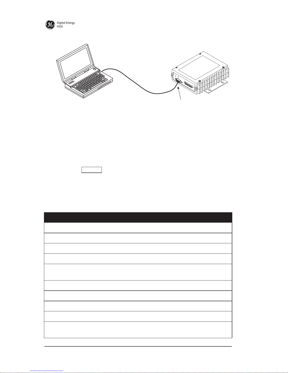
1. Connect a PC to the transceiver’s
P2
connector as shown in
Figure 6. If desired, a connecting cable may be assembled using
the information shown on Page 26.
CAUTION
POSSIBLE
EQUIPMENT
DAMAGE
CAUTION
POSSIBLE
EQUIPMENT
DAMAGE
Page 8
6 LCT 450 Installation/Operation Guide 05-4819A01, Rev. 08
Invisible place holder
Figure 6. PC Configuration Setup
2. Launch a terminal communications program, such as HyperTerminal (included with most Windows
TM
systems). Data parameters
are 8 data bits, no parity, and 1 stop bit (8N1). Data rate is determined by autobaud, but 1115200 bps is the preferred speed.
3. Press the key a few times (at half-second intervals) to
obtain the ready “>” prompt on the screen. Commands may now
be entered from the keyboard.
Table 1. Command Summary
Command Name
Function
ALARM
Alarm Summary
AMASK
Alarm Mask
AUDIO
Audio Monitor/Orderwire Status
BOOT
Reboot Radio
CHAN
Channel commands (RX/TX frequency, RF
power, bandwidth)
CKEY
Key TX Continuously (Digital Only)
DATAKEY
Key on Data Activity
DUMP
Read Current Unit Profile
EMP
Modem TX Audio Pre-Emphasis
FSET
Receive or Transmit frequency mini/max
value
PC Running Terminal Session
Transceiver
To DB-9
Management Port
ENTER
Page 9

05-4819A01, Rev. 08 LCT 450 Installation/Operation Guide
7
HELP
User Help
HREV
Display Hardware Revision
INIT
Initialize EEPROM Defaults
MODE
Radio Mode
MODEL
Model Number Information
MTYPE
Modem Family Type
OPT, OPTION,
OPTIONS
Display Authorized Options
OWM
Owner’s Message
OWN
Owner’s Name
PROG
Program
PWRL, PWRM, PWRH,
PWRRXH
Power Lo (5W), Medium (20W), Hi (25),
Extra-High (30W)
PTT
Push-to-Talk Delay
REF
Reference Frequency
RSSI
Received Signal Strength Indicator
RXTOT
Loss of RX Data Alarm Time
SER
Radio’s Serial Number
SHOW
Show Power Settings
SPECTRUM
Internal Spectrum Analyzer
SQUELCH
Squelch Operation
SREV
Software/Firmware Revision Level
STAT
Alarm Status
TEMP
Internal Temperature
TOT
TX Timeout-Timer
VERSION
Firmware Version
Table 1. Command Summary
(Cont’d)
Command Name
Function
Page 10

8 LCT 450 Installation/Operation Guide 05-4819A01, Rev. 08
DETAILED USER COMMANDS
The commands in this section may be used in two ways. First, you can
type only the command name to view the currently programmed data.
Secondly, you can set or change the existing data by typing the command, followed by a space, and then the desired entry. In the list
below, allowable programming variables, if any, are shown in brackets
following the command name.
ALARM
Alarm Summary
The
ALARM
command displays a summary of the radio's current operating condition. An eight-digit code will be presented which can be
decoded as described in “Major Alarms vs. Minor Alarms”.
AMASK [0000 0000-FFFF FFFF]
Alarm Mask
The
AMASK
command displays or sets which events cause an alarm
output signal to be active. Normally, the mask is
FFFF FFFF
, meaning
that any of the 32 possible events will activate the alarm output signal.
Entering the
AMASK
command alone displays the current setting of
alarm events in hexadecimal format. Entering the
AMASK
command
followed by an eight-digit hexadecimal number reprograms the specified events to trigger an alarm. The eight-digit hexadecimal number
used as the command parameter specifies 0 to 32 events that can
trigger the external alarm output. The hex value for the mask corresponds to the hex value for the
STAT
command. Each bit that is a '1'
identifies an alarm condition that can trigger the external output. For
more information on configuring the alarm response, contact GE
MDS.
ASENSE [HI/LO]
Alarm Sense
The
ASENSE
command sets or displays the sense of the alarm output
at Pin 6 of the COM2 port. Entering the
ASENSE
command alone
shows whether the alarm output is active high or low. Entering the
ASENSE
command followed by
HI
or
LO
resets the alarm output to
active high or low.
Page 11

05-4819A01, Rev. 08 LCT 450 Installation/Operation Guide
9
AUDIO [ON/OFF]
Audio Monitor/Orderwire Status
Used to set or display Audio Monitor/Orderwire functionality (on or
off)
BOOT [1, 2, OTHER]
Reboot Radio
Used to reboot to selected image or current image if no image specified.
CHAN [0-8, ALL]
[RXFREQ xxx.xxxx]
(MHz)
[TXFREQ xxx.xxxx]
(MHz)
[PWR [5, 20, 25, 30]
(Watts)
[BW [12.5, 25]
(kHz)
Channel Mods...
If only the first argument is given, then it displays the channel(s)
parameters. If a third (or greater) argument is given, then that channel
with have its parameters changed.
CKEY [ON/OFF] -
Digital Only
Key TX Continuously
The
CKEY
command enables or disables the continuously keyed func-
tion of the radio. When
CKEY
is set to ON, the radio is continuously
keyed and the Timeout Timer is disabled.
CTS [0-255]
Clear-to-Send Time
The CTS (clear-to-send) command selects or displays the timer value
associated with the CTS line response. The command parameter
ranges from
0 to 255 milliseconds.
For DCE operation, the timer specifies how long to wait after the RTS
line goes high, before the radio asserts CTS and the DTE can transmit
the data. A CTS value of zero keys the radio and asserts the CTS line
immediately after the RTS line goes high.
Page 12

10 LCT 450 Installation/Operation Guide 05-4819A01, Rev. 08
For CTS Key operation (see DEVICE command), the timer specifies
how long to wait after asserting the CTS, before sending data out the
DATA INTERFACE port. A timer value of zero means that data will be
sent out the data port without imposing a key-up delay. (Other delays
may be present based on selected radio operating parameters.)
CTSHOLD [0-60000]
Clear-to-Send Hold Time
Used in DEVICE CTS KEY mode, this command sets the amount of time
in milliseconds that CTS remains present after transmission of the last
character out the RXD pin of the
DATA port. This “hold time” can be
used to prevent squelch tail data corruption when communicating with
other radios.
The CTSHOLD setting can range from 0 to 60000 ms (i.e., 60 seconds).
The default value is
0, which means that CTS will drop immediately
after the last character is transmitted. If the command is entered when
the radio is in
DEVICE DCE mode, the response CTSHOLD N/A is dis-
played.
DATAKEY [ON/OFF]
Key on Data Activity
The
DATAKEY command enables or disables the ability of the radio to
key the transmitter as data is received at the
DATA INTERFACE con-
nector. Asserting RTS keys the radio regardless of this command setting.
If
DATAKEY is set to ON, the radio will key when a full data-character
is received at the transceiver's
DATA INTERFACE connector. If
DATAKEY is set to OFF, the radio needs to be keyed by asserting RTS.
DEVICE [DCE, CTS KEY]
Data Device Mode
The
DEVICE command controls or displays the device behavior of the
radio. The command parameter is either
DCE or CTS KEY.
Page 13

05-4819A01, Rev. 08 LCT 450 Installation/Operation Guide 11
In DCE mode (the default setting), CTS will go high following RTS,
subject to the CTS programmable delay time. If the
DATAKEY com-
mand is set to
ON, keying can be stimulated by the input of characters
at the data port. Hardware flow control is implemented by signaling
the CTS line if data arrives faster than it can be buffered and transmitted.
In CTS KEY mode, the radio is assumed to be controlling another radio.
It will still key based on the RTS line, but the CTS line is used as a keyline control for the other radio. CTS is asserted immediately following
the receipt of RF data, but data will not be sent out the
DATA INTER-
FAC E port until after the CTS programmable delay time has expired.
(This gives the other radio time to key.)
DUMP
Read Current Unit Profile
This command causes all of the programmed settings to be displayed.
EMP [ON/OFF]
Modem TX Audio Pre-Emphasis
This command displays or sets the TX pre-emphasis and RX
De-Emphasis when the radio is operating with the analog mode and
the radio's modem is turned off (
MODEM NONE). It should be set to
match the other radios in the system. The use of pre and de-emphasis
can help reduce the detrimental influence of high frequency audio
noise.
FSET
Receive or transmit frequency min/max value
HELP
User Help
Show available commands.
HREV
Display hardware revision
Page 14

12 LCT 450 Installation/Operation Guide 05-4819A01, Rev. 08
INIT
Initialize EEPROM Defaults
The INIT command is used to re-initialize the radio's operating parameters to the factory defaults. This may be helpful when trying to
resolve configuration problems that may have resulted from the entry
of one or more improper command settings. If you are unsure of which
command setting may have caused the problem, this command allows
you to get back to a known working state. The following changes to
the radio are made when
INIT is entered:
•
CTS is set to 0
• DATAKEY is set to ON
• DEVICE is set to DCE
• PTT is set to 0
• SCD is set to 0
• TOT is set to 30 seconds and set to ON
• PWR is set to +37 dBm (5 watts)
All other commands remain as previously set.
MODE [NORMAL, TEST]
Radio Mode
This command puts the radio into a
TEST or NORMAL mode. In the test
mode, it disables the radio from looking at the hardware channel select
lines and automatically selects Channel 0.
MODEL, MODEL1, MODEL2
Model Number Information
MTYPE [SD | X710_AE | X710_B | LOOPBACK]
Modem Family Type
OPT, OPTION, OPTIONS
Display Authorized Options
Page 15

05-4819A01, Rev. 08 LCT 450 Installation/Operation Guide 13
OWM [XXX...]
Owner's Message
This is a command to display or program an owner's message. To program the owner's message, type
OWM then the message, followed by
an ENTER keypress.
To display the owner's message, type
OWM, followed by an ENTER
keypress. The owner's message appears on the display.
OWN [XXX...]
Owner's Name
This is a command to display or program an owner's name. To program the owner's name, type
OWN then the name, followed by
ENTER.
To display the owner's name, type
OWN then ENTER. The owner's
name appears on the display.
PROG
Program
The
PROG command used for serial reprogramming - spoof entry into
the bootloader.
PROGRAM
Program
The
PROGRAM command spoofing MDS x710 bootloader program
command to start serial reprogramming. Erases and programs inactive
image via serial port with xon/xoff flow control. Returns when complete. If successful active image is switched. Only valid after program
or prog command at
LOADER> prompt. Used for serial reprogram-
ming.
PWRL [0-30], PWRM [0-30], PWRH [0-30],
PWRXH [0-30]
Sets Power Level
This command sets the power level value for this name. This name is
used for the power calibration command (CPWR). PWRL defaults to
5 watts, PWRM defaults to 20, PWRH is 25 and PWRXH is 30 watts.
Page 16

14 LCT 450 Installation/Operation Guide 05-4819A01, Rev. 08
PTT [0-255]
Push-to-Talk Delay
This command sets or displays the key-up delay in milliseconds. This
timer specifies how long to wait after the radio receives a key signal,
before actually keying the radio.
REF [xxxxx]
Reference Frequency
RSSI
Received Signal Strength Indicator
This command continuously displays the radio's Received Signal
Strength Indication (RSSI) in dBm units, until you press the Enter key.
Incoming signal strengths from -50 dBm to -120 dBm can be read.
NOTE: The RSSI samples the incoming signal for one to two seconds
before providing an average reading to the connected PC.
RTU [ON/OFF/0-80] Digital Only
RTU Emulator
This command enables or disables the radio's internal RTU simulator,
which runs with proprietary factory polling programs such as
poll.exe
and
rsim.exe. The internal RTU simulator is available whenever a
radio has diagnostics enabled. This command also sets the RTU
address that the radio will respond to.
The internal RTU can be used for testing system payload data or
pseudo bit error rate testing. It can be helpful in isolating a problem to
either the external RTU or the radio.
RXTOT [NONE, 1-255]
Loss of RX Data Alarm Time
The
RXTOT command selects or displays the receive time-out timer
value in minutes. This timer triggers an alarm (Event 12) if data is not
detected within the specified time.
Entering the
RXTOT command without a parameter displays the timer
value in minutes. Entering the
RXTOT command with a parameter
ranging from
0 to 255 resets the timer in minutes. Entering the RXTOT
command with the parameter
NONE disables the timer.
Page 17

05-4819A01, Rev. 08 LCT 450 Installation/Operation Guide 15
SCD [0-255]
Soft-Carrier Dekey
This command displays or changes the soft-carrier dekey delay in milliseconds.
This timer specifies how long to wait after the removal of the keying
signal before actually releasing the transmitter. A value of 0 milliseconds will unkey the transmitter immediately after the removal of the
keying signal.
SER
Radio's Serial Number
This command displays the radio's serial number as recorded at the
factory.
SHOW [DC, PORT, PWR]
Show Power Settings
The
SHOW command displays different types of information based on
the command variables. The different parameters are:
•
DC-Display DC input/output voltages
•
PWR-Display RF power output
SPECTRUM [xxx.xx]
Internal Spectrum Analyzer
Activates the built-in spectrum analyzer tool (see Figure 8) that can be
displayed on a connected PC. This tool is helpful in diagnosing interference problems on or near your channel frequency.
Access the spectrum analyzer by entering spectrum at the command
prompt. A display appears showing detected signals on your current
channel.
Optionally, you can specify a frequency at the command prompt to
view the surrounding spectrum of that frequency. To do this, enter
spectrum xxx.xx, where xxx.xx is the frequency in MHz.
Page 18

16 LCT 450 Installation/Operation Guide 05-4819A01, Rev. 08
A typical spectrum analyzer display is shown in Figure 8. The display
creates a received signal strength indication (RSSI) vs. frequency plot
for the frequency and surrounding signals. By analyzing the display,
you can determine the presence of other signals near the transceiver's
operating frequency. This information can be helpful in troubleshooting interference problems.
SQUELCH [AUTO, BYPASSED]
Squelch Operation
Set or display analog squelch bypass.
SREV
Software/Firmware Revision Level
This command displays the software revision level of the transceiver
firmware.
STAT
Alarm Status
This command displays the current alarm status of the transceiver.
If no alarms exist, the message
NO ALARMS PRESENT appears.
If an alarm does exist, a two-digit code (
00-31) is displayed and the
alarm is identified as “Major” or “Minor.” A brief description of the
alarm code is also given.
TEMP
Internal Temperature
This command displays the internal temperature of the transceiver in
degrees Celsius.
TOT [1-255, ON, OFF]
TX Timeout-Timer
This command sets or displays the transmitter Time-out Timer value
(1-255 seconds), as well as the timer status (
ON or OFF). If the timer is
on, and the radio remains keyed for a longer duration than the
TOT
value, the transmitter is automatically unkeyed.
Page 19

05-4819A01, Rev. 08 LCT 450 Installation/Operation Guide 17
When this happens, the radio must be commanded back to an unkeyed
state before a new keying command is accepted. The default timer
value is
30 seconds.
VERSION
Firmware Version
Displays package version information for each firmware image.
RADIO TESTS & TEST MODE COMMANDS
The following are checks and settings that can be performed by a technician to ensure optimal performance of the radio. For most tests, it
will be necessary to connect a PC to the radio as described in SOFT-
WARE COMMANDS on Page 5.
Antenna System SWR Check
SWR is a parameter related to the ratio between forward transmitter power and the reflected power from the antenna system.
As a general guideline, reflected power should not exceed 10%
of the forward power (≈ 2:1 SWR). A high SWR may result in
decreased performance, and should be corrected.
The transceiver’s
TXD/RXD LEDs will light when the SWR is too
high. Actual SWR can be measured by connecting a reflected
power meter, such as a Bird Model 43
™
directional wattmeter
with the proper element installed, between the transceiver and
the antenna system. Use the
KEY/DEKEY commands described
below to control the transmitter during these tests. Test transmissions should be kept as brief as possible.
If the results are normal, record them for comparison during
future routine preventative maintenance. Abnormal readings
indicate a possible trouble with the antenna or the transmission
line that will need to be corrected. Look for cable damage, poor
connections, or improper positioning of the antenna (such as
having the antenna whip too close to a metal surface).
Page 20

18 LCT 450 Installation/Operation Guide 05-4819A01, Rev. 08
Over-Temperature Check
If the transmitter is approaching an out-of-tolerance temperature condition, an error code is issued (see Table 3) and the
PWR lamp will
flash. Further operation may be inhibited. Over-temperature conditions should be investigated and resolved before further use of the
radio.
To read the actual internal temperature of the radio (in degrees Celsius), the
TEMP command may be issued from a PC. Excessive temper-
atures may be caused by inadequate ventilation of the transceiver case,
or operating the unit beyond its rated duty cycle (see “SPECIFICA-
TIONS” on Page 26).
Test Mode Commands
The following commands may be used by a technician to test the radio
or to make advanced setting changes during installation and maintenance activities.
BW [xxxxx]
Channel Bandwidth
This command displays the current bandwidth or sets the modem
bandwidth for channel 0. This command also sets the appropriate deviation for this bandwidth.
CHAN [0-8, ALL]
[RXFREQ xxx.xxxx] (MHz)
[TXFREQ xxx.xxxx] (MHz)
[PWR [5, 20, 25, 30] (Watts)
[BW [12.5, 25] (kHz)
Channel Mods...
If only the first argument is given, then it displays the channel(s)
parameters. If a third (or greater) argument is given, then that channel
with have its parameters changed.
Page 21

05-4819A01, Rev. 08 LCT 450 Installation/Operation Guide 19
DKEY
Unkey Transmitter
This command deactivates the transmitter after it has been keyed with
the
KEY command.
KEY
TX Key
This command activates the transmitter. See also the
DKEY command.
MODEM [xxxx]
Analog/Digital Modem Selection
This command selects the radio's modem characteristics. For digital
operation enter
MODEM xxxx, where xxxx equals the modem selection
of the radio (
9600 or 19200). For analog operation with an external
modem, enter
NONE for this parameter.
When the
MODEM command is set to NONE, the analog TX Input and
RX Audio outputs of the
DATA INTERFACE will be used to interface
with the connected external modem, and digital operation is disabled.
These levels must be set to complement the audio signal level requirements of the external modem. See “RXLEVEL [-20 to 0]” and
“TXLEVEL [-20 to 0, AUTO]” for details on setting these levels.
PWR [Watts]
NOTE: This function may not be available in all units, depending on
certification requirements for a particular country.
TX RF Power Output Level
This command displays the current power level in watts or sets the
desired RF forward output power setting for channel 0 of the radio.
The
PWR command parameter is specified in watts and its settings are
5, 20, 25, 30. The default setting is 5 watts. To read the actual (mea-
sured) power output of the radio, use the
SHOW PWR command.
RX [xxx.xxxx]
Receive Frequency
This command displays the current receive frequency or selects the
radio's receive frequency (in MHz) for channel 0. The frequency step
size is 6.25 kHz.
Page 22

20 LCT 450 Installation/Operation Guide 05-4819A01, Rev. 08
If the radio’s frequency has not been programmed at the factory, a
default frequency will be programmed in the radio near the center of
the frequency band.
SELCHAN [0-8]
Select Channel
This command causes the radio to go to another channel when the
radio is in
MODE TEST. It causes the radio to select appropriate RX and
TX frequencies, power level and bandwidth for that channel.
TX [xxx.xxxx]
TX Frequency
This command displays the radio's transmit frequency in MHz or
changes channel 0's transmit frequency. The frequency step size is
6.25 kHz.
If the frequency has not been programmed at the factory, a default frequency will be programmed in the radio near the center of the frequency band.
TROUBLESHOOTING
For proper operation, all radios in the network must meet these basic
requirements:
• Adequate and stable primary power
• Secure connections (RF, data and power)
• A clear transmission path between stations
• An efficient antenna system providing adequate received signal
strength.
• Proper programming of the transceiver’s operating parameters
• The correct interface between the transceiver and the connected
data equipment (correct cable wiring, proper data format, timing, etc.)
Page 23

05-4819A01, Rev. 08 LCT 450 Installation/Operation Guide 21
LED Indicators
The LED status indicators (Figure 7) are an important troubleshooting
aid and should be checked whenever a problem is suspected. Table 2
describes the function of each status LED on the front panel of the
radio.
Invisible place holder
Figure 7. LED Indicators
Additional LED indications—for trouble conditions:
TXD/RXD
lit: High Standing Wave Ratio (SWR). Check antenna
system.
PWR lamp flashing: Over temperature (Observe duty cycle, ensure
adequate ventilation)
Event Codes
When an alarm condition exists, the transceiver creates a code that can
be read on a connected terminal. These codes can be helpful in
resolving many system difficulties. Refer to Table 3 (Page 22) for a
definition of the event codes.
Table 2. LED Status Indicators
LED Name Description
PWR • Continuous—Power applied, no problems detected.
• Rapid flash (5 times-per-second)—Alarm indication.
TXD Unit is transmitting.
RXD Unit ready to receive data (not transmitting).
DCD Message is being received.
PWR
DCD
TXD
RXD
Page 24

22 LCT 450 Installation/Operation Guide 05-4819A01, Rev. 08
Checking for Alarms—STAT command
To check for alarms, connect a terminal to the radio’s P2 Programming
& Diagnostic port. See P2 PROGRAMMING & DIAGNOSTIC
INTERFACE on Page 26 for pinout information.
Enter
STAT on the connected terminal. If no alarms exist, the message
NO ALARMS PRESENT appears on the display.
If an alarm does exist, a two-digit alarm code (00–31) is displayed and
the event is identified as a Major or Minor Alarm. A brief description
of the alarm is also given.
Major Alarms vs. Minor Alarms
Major Alarms—report serious conditions that generally indicate a
hardware failure, or other abnormal condition that will prevent (or
seriously hamper) further operation of the transceiver. Major alarms
generally indicate the need for factory repair. Contact your factory
representative for assistance.
Minor Alarms—report conditions that, under most circumstances will
not prevent transceiver operation. This includes out-of-tolerance conditions, baud rate mismatches, etc. The cause of these alarms should
be investigated and corrected to prevent system failure.
Event Code Definitions
Table 3 contains a listing of event codes that may be reported by the
transceiver. The codes shown are a subset of a larger pool of codes
used for various GE MDS products. For this reason, the table does not
show a sequential listing of all code numbers. Only the codes applicable to this product are shown.
Table 3. Event Codes
Event
Code
Event
Class Description
01 Major Improper software detected for this radio model.
04 Major The RF synthesizer is reporting an out-of-lock
condition.
08 Major The system is reporting that it has not been
calibrated. Factory calibration is required for proper
radio operation.
Page 25

05-4819A01, Rev. 08 LCT 450 Installation/Operation Guide 23
Internal Spectrum Analyzer
The radio contains a built-in spectrum analyzer tool (Figure 8) that can
be displayed on a connected PC. The tool is helpful in diagnosing
interference problems on or near your channel frequency.
Access the spectrum analyzer by entering
spectrum at the command
prompt. A display appears showing detected signals on your current
channel.
Optionally, you can specify a frequency at the command prompt to
view the surrounding spectrum of that frequency. To do this, enter
spectrum xxx.xx, where xxx.xx is the frequency in MHz.
As shown in Figure 8, the display creates a received signal strength
indication (RSSI) vs. frequency plot for the frequency and surrounding signals. By analyzing the display, you can determine the
presence of other signals near the transceiver’s operating frequency.
This information can be helpful in troubleshooting interference problems.
12 Major Receiver time-out. No data received within the
specified receiver time-out time.
13 Minor A Transmitter timeout was detected. The radio
stayed keyed longer than the duration specified by
the TOT command.
17 Minor A data parity fault has been detected on the
PAYLOAD port. This usually indicates a parity
setting mismatch between the radio and the
customer equipment.
18 Minor A data framing error has been detected on the
PAYLOAD port. This may indicate a baud rate
mismatch between the radio and the customer
equipment.
26 Minor The DC input voltage is out-of-tolerance. If the
voltage is too far out of tolerance, operation may fail.
31 Minor The transceiver’s internal temperature is
approaching an out-of-tolerance condition. If the
temperature drifts outside of the recommended
operating range, system operation may fail.
Table 3. Event Codes (Cont’d)
Event
Code
Event
Class Description
Page 26

24 LCT 450 Installation/Operation Guide 05-4819A01, Rev. 08
Invisible place holder
Figure 8. Internal Spectrum Analyzer Display
P1 CONTROL INTERFACE
Table 4 lists the pin functions on the P1 Control Interface connector.
Table 4. P1 Control Interface Pin Descriptions (DB-25)
Pin No. Description
1 No connection (NC)
2 Audio Isolated Ground
3 No connection (NC)
4 Detected Audio
5 Channel Select 3 (see Note 1).
6 RXD+ (RS-485/422 digital). Output from radio.
7 PTT Keying signal (see Note 2)
8 RXD- (RS-485/422 digital) Output from radio.
9 No connection (NC)
10 No connection (NC)
Page 27

05-4819A01, Rev. 08 LCT 450 Installation/Operation Guide 25
Note 1:
Channel select decoding as follows: High = no connection; Low = Gnd. See
table below for radio channel selections.
Note 2:
Provide low impedance path to ground to key transmitter.
11 Audio Isolated Ground
12 No connection (NC)
13 No connection (NC)
14 Channel Select 2 (See Note 1)
15 No connection (NC)
16 RS-485/422 Isolated Ground
17 TX Audio input to radio
18 Channel Select Isolated Ground
19 Channel Select 0 (Note 1)
20 No connection (NC)
21 PTT Isolated Ground
22 No connection (NC)
23 Channel Select 1 (Note 1)
24 TXD+ (RS-485/422 digital). Input to radio.
25 TXD- (RS-485/422 digital) Input to radio.
Table 5. Channel Selection Table
Channel 3 Channel 2 Channel 1 Channel 0 Selected
High (future use) High High High 1
High (future use) High High Low 2
High (future use) High Low High 3
High (future use) High Low Low 4
High (future use) Low High High 5
High (future use) Low High Low 6
High (future use) Low Low High 7
High (future use) Low Low Low 8
Table 4. P1 Control Interface Pin Descriptions
Page 28

26 LCT 450 Installation/Operation Guide 05-4819A01, Rev. 08
P2 PROGRAMMING & DIAGNOSTIC
INTERFACE
Table 4 lists the pin functions on the DB-9 DIAGNOSTIC INTERFACE
connector.
SPECIFICATIONS
GENERAL
Frequency Range*: 450–512 MHz
Number of Channels: 8
RECEIVER
Maximum Usable Sensitivity: 0.35 uV for 12 dB SINAD
Bandwidth: 12.5 kHz
Maximum Applied Signal: +28 dBm
TRANSMITTER
RF Carrier Power: 5 Watts to 30 Watts
Duty Cycle: 25%
Output Impedance: 50 Ω
Channel Spacing: 12.5, 25 kHz
FCC Emission Designators:
6.25 kHz B/W: 4K00F1D, 4K00F2D,4K00F3D
Table 6. Diagnostic Interface Pin Descriptions (DB-9)
Pin No. Description
1 No connection (NC)
2 RX Data
3 TX Data
4 No connection (NC)
5 Signal Ground
6 No connection (NC)
7 No connection (NC)
8 No connection (NC)
9 No connection (NC)
Page 29

05-4819A01, Rev. 08 LCT 450 Installation/Operation Guide 27
12.5 kHz B/W: 9K30F1D, 9K30F2D, 9K30F3D
25.0 kHz B/W: 16K5F1D, 16K5F2D, 16K5F3D
DATA CHARACTERISTICS
(P1 Control Interface Connect)
Payload Signaling Type: CCITT V.23
Connector Types: DB-25 Female
Payload Data Rate: 1200 bps
DATA CHARACTERISTICS
(P2 Programming & Diagnostic Port)
Connector Type: DB-9F
Signaling Standard: RS-232
PRIMARY POWER
Voltage: 13.6 Vdc (+/- 15%)
Negative-Ground Systems Only
TX Supply Current: 8 Amperes (Typical) @ 30 Watts Output
RX Supply Current: Operational—125 mA, Nominal
Power Connection: 5-inch “pigtail” (14 AWG) with Tyco/AMP
connector (Part No. 172129-1)
Fuse: 8-Ampere, internal
Page 30

28 LCT 450 Installation/Operation Guide 05-4819A01, Rev. 08
Page 31

Installation Guide
Page 32

GE MDS, LLC
Rochester, NY 14620
General Business: +1 585 242-9600
FAX: +1 585 242-9620
Web: www.gemds.com
175 Science Parkway
 Loading...