

GE LBI-31482 Maintenance Manual

Mobile Communications
MAINTENANCE MANUAL
FOR
GENERAL ELECTRIC
33-50 MHz
Beacon Monitor Pager
Maintenance Manual
LBI-31482
Printed in U.S.A.

Copyright © June 1985, General Electric Company
TABLE OF CONTENTS
Page
DESCRIPTION . . . . . . . . . . . . . . . . . . . . . . . . . . . . . . . . . . . . . . . . . . . . . . . . . . . . . 2
OPERATION . . . . . . . . . . . . . . . . . . . . . . . . . . . . . . . . . . . . . . . . . . . . . . . . . . . . . . 2
BATTERY INFORMATION . . . . . . . . . . . . . . . . . . . . . . . . . . . . . . . . . . . . . . . . . . . . . . 2
CIRCUIT ANALYSIS . . . . . . . . . . . . . . . . . . . . . . . . . . . . . . . . . . . . . . . . . . . . . . . . . . 2
Receiver . . . . . . . . . . . . . . . . . . . . . . . . . . . . . . . . . . . . . . . . . . . . . . . . . . . . . . 2
Sequential Tone Decoder . . . . . . . . . . . . . . . . . . . . . . . . . . . . . . . . . . . . . . . . . . . . . 3
DETERMINATION OF TONE FREQUENCIES . . . . . . . . . . . . . . . . . . . . . . . . . . . . . . . . . . . 5
GE Format . . . . . . . . . . . . . . . . . . . . . . . . . . . . . . . . . . . . . . . . . . . . . . . . . . . . . 5
Quik-Call II Format . . . . . . . . . . . . . . . . . . . . . . . . . . . . . . . . . . . . . . . . . . . . . . . . 5
SERVICING
Disassembly . . . . . . . . . . . . . . . . . . . . . . . . . . . . . . . . . . . . . . . . . . . . . . . . . . . . 6
Alignment Procedure . . . . . . . . . . . . . . . . . . . . . . . . . . . . . . . . . . . . . . . . . . . . . . . 6
Troubleshooting . . . . . . . . . . . . . . . . . . . . . . . . . . . . . . . . . . . . . . . . . . . . . . . . . . 8
OUTLINE DIAGRAM . . . . . . . . . . . . . . . . . . . . . . . . . . . . . . . . . . . . . . . . . . . . . . . . . 11, 12
SCHEMATIC DIAGRAM . . . . . . . . . . . . . . . . . . . . . . . . . . . . . . . . . . . . . . . . . . . . . . . 13
PARTS LIST AND PRODUCTION CHANGES . . . . . . . . . . . . . . . . . . . . . . . . . . . . . . . . . . . . 14
PARTS BREAKDOWN . . . . . . . . . . . . . . . . . . . . . . . . . . . . . . . . . . . . . . . . . . . . . . . . . 15
TYPICAL SPECIFICATIONS
FCC Identification Number AXA9ERER-145-A1, B1, C1, D1
GE Type Numb er ER-145-A1: 41-45 MHz
ER-145-B1: 37-41 MHz
ER-145-C1: 33-37 MHz
ER-145-D1: 45-50 MHz
Frequency Range 33-50 MHz
Type of Operation Tone, Voice and Monitor
Signalling System Two-Tone Sequential
Audio Power Output (4 Ohm Speaker)
HI
LO
150 Milliwatts
20 Milliwatts
TYPICAL SPECIFICATIONS (CONT.)
Current Drain (at 2.5 Volts)
Standby
Receive
5.2 milliamperes
105 milliamperes
Battery Life
Nicke1-Cadmium
Mercury
25 hours
115 hours
Modulation Acceptance ±8 kHz
Channel Spacing 20 kHz
Selectivity (EIA) -65 dB
Paging Sensitivity 7 uV/meter
Usable Sensitivity (12 dB SINAD) 18 uV/meter
Spurious Response -56 dB
Frequency Stability ±5 PPM
Audio Distortion 5%
Dimensions (H x W x D) 110 x 52 x 36 millimeters (with belt clip)
(4.3 x 2 x 1.4 inches)
Weight 160 grams (5.66 ounces) with battery and belt clip
COMBINATION NOMENCLAURE
Digits 1 & 2
Digit 3
Digit 4 Digit 5 Digit 6 Digit 7 Digit 8
Product
Code
Tone
Option
Control Color
Channel
Spacing
Frequency
Range
Distribution
L
T99/Quick Call
M
Separator
W
Black
5
20 kHz
B
33-37 MHzAAll Other
P8
Pager
R
Red
C
37-41 MHz
D
Dealer
D
41-45 MHzBLess Xtals &
Reeds
E
45-50 MHzELess Xtals &
Reeds Dealer
LBI-31482 LBI-31482
1
DESCRIPTION
The General Electric Beacon Monitor Pager is a
highly reliable, extremely compact receiver for tone and
voice paging and channel monitor applications.
The Pager is equipped with a built-in speaker, earphone
jack and antenna, and is shipped with two nickel-cadmium
rechargeable batteries and an external earphone.
The receiver is housed in a ruggedly-constructed case,
with all operating controls conveniently mounted on the top
and side of the case. An accessory jack on the bottom of the
radio is provided for an external earphone.
Power for the Pager is normally supplied by two rechargeable nickel-cadmium batteries that fit in a separate
battery compartment in the bottom section of the case. The
batteries can be recharged either in or out of the receiver.
If desired, the Pager can also be operated by mercury,
zinc-carbon, or alkaline batteries. However, these batteries
are not rechargeable.
The sprin g c lip on the Page r m ay be us ed to cli p th e ra dio to a pocket or belt.
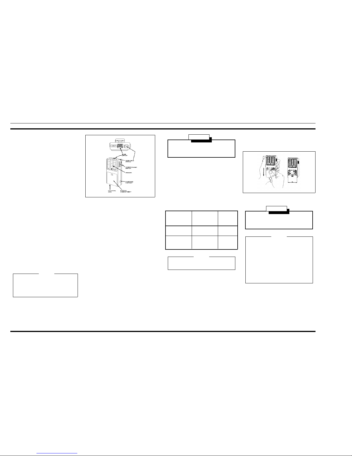
OPER A TION
Turn the receiver on by placing the Power/Volume
switch to Volume HI position (See Figure 1). Several short
bursts of tone should be heard. The receiver is now ready to
receive messages.
Before a message is received, a short, interrupted burst
of tone will be heard, followed by a voice message. As soon
as the message is completed, press the Reset/Monitor button
to reset the receiver.
The Pager operates in either the SELECTIVE or MONITOR mode.
In the SELECTIVE mode, the Pager operates as a tone
and voice receiver, and allows only those calls that are tone
coded for the Pager to be heard. After the call has been received, the Pager switches automatically to the MONITOR
mode. The Pager will remain in the MONITOR mode, receiving all calls on the channel until the RESET switch is
pressed.
Placing the mode switch in the MONITOR position allows all calls on the channel to be heard whether they are
tone coded or not. The Pager will squelch when no calls are
being received.
An earphone is available for use in high-noise areas, or
for receiving messages in private. Plugging the earphone
into the earphone jack disables the Pager speaker so that
messages can only be heard through the earphone.
After receiving the first message, it may be desirable to
reduce the volume by placing the OFF-HI switch in the LO
position.
CHARGERS
A single-unit desk-top charger and a multi-unit charger
are available for recharging the nickel-cadmium batteries in
the radio as well as spare ni ck el-cadmium batteries.
Temperature characteristics of nickel cadmium batteries
prevent a full charge at temperature extremes. For maximum capacity, recharge the batteries at room temperatures
between 65° to 85° Fahrenheit.
To use the charger, connect the power cable to an appropriate power source. Place the Pager into the charger. The red
light will turn on, indicating that the Pa g e r is being charged. To
charge spare nickel-cadmium batteries, place them into t h e battery insert. A second red light will come on to indicate that the
batteries are being charged.
BATTERY INFORMATION
Two different types of batteries are normall y used in the
Pager. The type and battery life for e a ch b at tery is shown in the
following chart.
BATTERY
TYPE
PART
NUMBER
TYPICAL
BATTERY
LIFE
Nickel-Cadmium
(Rechargeable)
19A703502P1 25 Hours
Mercury (Not
Rechargeable)
19A701300P1
Mallory MP401,
Eveready EP401E
115 Hours
BATTERY REPLACEMENT
The Pager is shipped from the factory ready for immediate
operation upon installation of two fu lly ch ar g ed b atte ries .
To install or replace the batteries:
1. Slide the Pager OFF-HI switch to the OFF position.
2. Press in the battery cover on the ridges at the top of
the cover and slide cov er down a s sho wn .
3. Replace batteries according to the (+) and (-) signs in
the battery compartmen t.
4. Slide battery cover back into place.
CIRCUIT ANALYSIS
RECEIVER
Paging receiver Types ER-145-A1, -B1, -C1 and -D1 are
double-conversion, superheterodyne receiver for tone and
voice paging in the 33-50 MHz range. One circuit board con-
Failure to press the Reset button after receiving a
message may shorten battery life. Do not press the
Reset button while receiving a message or an alert
tone. Doing so will prevent you from receiving the
message.
NOTE
Figure 1 - Operating Controls
Do not attempt to charge mercury, alkaline or zinccarbon batteries. To do so may cause the batteries to
explode.
WARNING
Nickel-cadmium batteries should be fully re-charged
before using.
NOTE
Do not dispose of either the rechargeable battery or the
Mercury battery by burning. To do so may cause a b attery to explode.
WARNING
There is no way to dispose of mercury batteries without possible polution except by returning them to the
manufacturer for recycling.
Mallory Battery Company will buy all used mercury
batteries at the current market price. Batteries are to be
shipped prepaid, enclosing a packing slip indicating
who is to receive payment for the batteries to:
Mallory Battery Company
Plant #2
Lexington, North Carolina 27292
NOTE
Figure 2 - Battery Replacement
LBI-31482 LBI-31482
2
tains both tone and voice circuits, and utilizes both discrete
components and Thick Film Integrated Circuit Modules (IC’s).
The receiver has intermediate frequencies of 10.7 MHz and
455 kHz. Adjacent channel selectivity is provided by using
two, 2-pole ceramic filters. References to symbol numbers
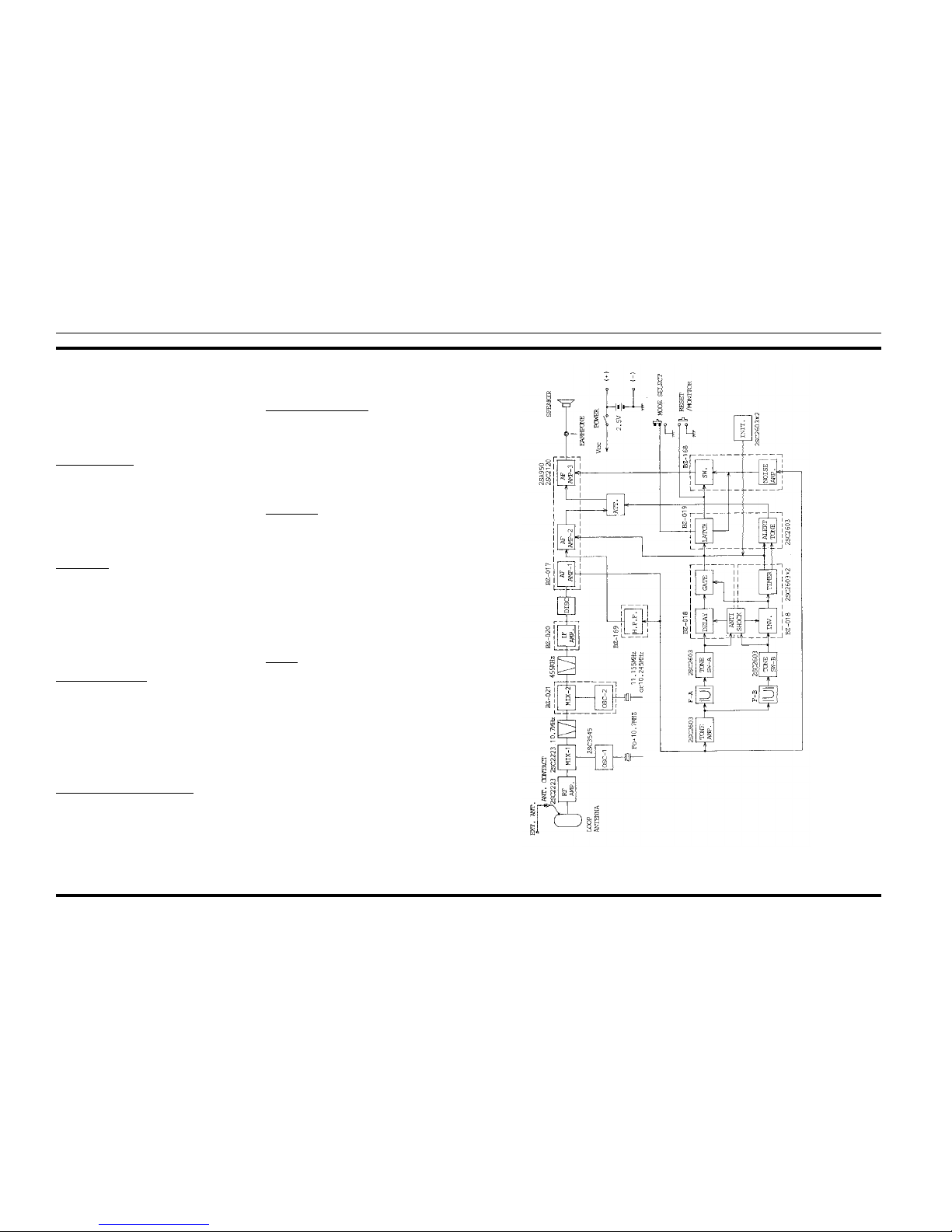
mentioned in the following text are found in the Outline Diagram, Schematic Diagram and Parts List (See Table of Contents). A block diagr am o f t he r ece i ve r is shown i n F igure 3.
Receiver Front End
An RF signal from the antenna is coupled through the antenna circuit to the base of RF amplifier Q1. The antenna circuit consists of L1, CV1 and C2. The circuit is tuned by CV1.
The output of Q1 is coupled through three tuned circuits
that provide most of the front end selectivity. The tuned circuits are L2, L3, L4 and associated circuitry. The output of L4
is coupled through C10 to the base of the first mixer .
1st Oscillator
Q2, X1, L5 and associated circuitry make up a Colpitts oscillator. The frequency is controlled by a third mode crystal operated at one third of the required injection frequency. L5 is
used to set the oscillator on frequency. R3 is in parallel with
X1 to ensure operation on the third overtone of the crystal. The
injection frequency is the operating frequency (-) 10.7 MHz,
and is coupled through C16 to the first mixer. L6 is tuned to
three times, the crystal frequency. The output to the 1st mixer
is approximately 60-90 millivolts rms.
1st Mixer and IF Filter
RF from the Pager front end is applied to the base of first
mixer Q3. Injection voltage from the first oscillator is also applied to the base of Q3. The 10.7 MHz first IF frequency is
coupled through L7 to 10.7 MHz filter FL1. L7 is used to
match the mixer output to the input of FL1.
The highly-selective filter provides the first portion of the
receiver IF selectivity. The 10.7 MHz output of FL1 is applied
to the second mixer IC (Al).
2nd Oscillator, Mixe r and IF Filter
Al and associated circuitr y make u p the 2nd oscilla tor and
mixer. The crystal for the oscillator is X2. The oscillator operates at 10.245 MHz for low side injection of the 2nd IF (standard), or 11.155 MHz for high side injection for those radios
determined to be operating on a tweet frequency. This frequency is mixed with the 10.7 MHz input to provide the 455
kHz 2nd IF frequency.
The output of Al is coupled through ceramic filter FL2
which provides the 455 kHz selectivity. The filter output is applied to IF amplifier A2.
IF Amplifier and Detector
A2 and associated circuitry make up the IF amplifier. The
amplifier IC also provides the 455 kHz limiting. The output of
A2 is applied to the discriminator.
The discriminator demodulates the 455 kHz signal. This
type of detector provides a high degree of AM rejection. The
recovered audio, tone and noise is applied to audio amplifier
IC A51.
Audio Stages
The discriminator output is applied to buffer/pre-amp A51.
One output at A51-4 is coupled through high-pass filter A56
which filters out frequencies under 200 Hz to eliminate any
Channel Guard (CTCSS) tone. The filter output is applied to
squelch circuit A55, and to the decoder circuitry.
Applying the proper sequential tones to the receiver activates the decoder circuitry and audio stages, causing the second alert tone to be heard at the speaker.
After the alert tone is heard, the output of A51 is applied to
the push-pull audio amplifiers Q51 and Q52, and then to the
speaker.
Squelch
Squelch control IC A55 monitors noise in the 30-40 kHz
range on A55-1. When there is no carrier present, the noise is
above a squelch threshold set by RV52. This condition makes
A55-7 high, shutting off the audio amp at A51-9. When a carrier is present, the noise level drops below the threshold driving A55-7 and A51-9 low. This turns the audio amp on
allowing transmissions on the channel to be monitored.
SEQUENTIAL TONE DECODER
The decoder is a two-reed, sequential tone decode r for operation with any two-tone sequential encoder in individual call
applications.
The two reeds mount at the bott om of the circuit board, and
are available for operation on tone frequencies in the 288.5 to
2000 Hz range.
Figure 3 - Pager Block Diagram
LBI-31482 LBI-31482
3
The pager is also compatible with Quik-Call II two-tone
paging systems, and operates in both individual call and
group call applications.
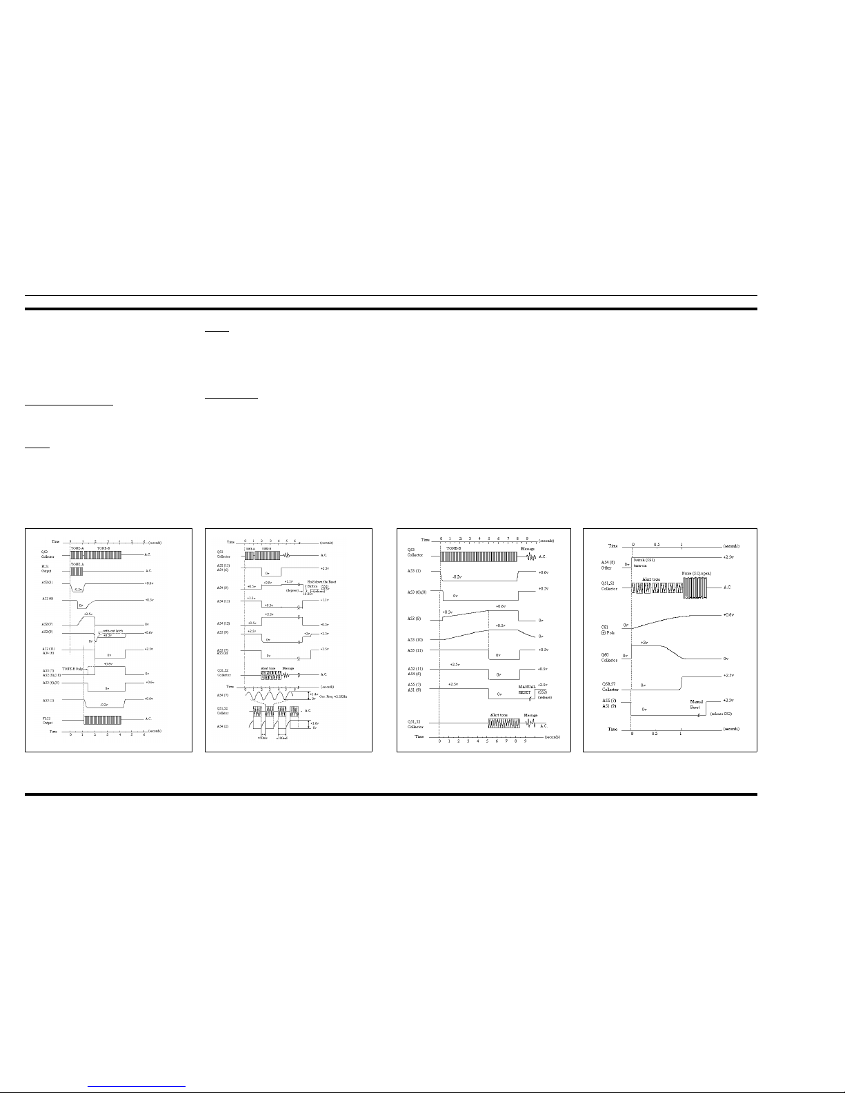
Timing waveforms for the decod er c i rc uitry are shown in
Figures 4-1, 4-2 and 5-1, 5-2. It is recommended that these
waveforms be studied in conjunction with the circuit analysis for a better understanding of the d ec o d er o peration.
Tone Amplifiers & Reeds
When the proper tone sequence is applied to the Pager,
the discriminator output is applied to buffer/amplifier A 51-1.
Tone A
When an HE signal containing Tone A is applied to the
Pager for approximately one second, the output at A51-2 is
applied to limiter-amplifier Q53. The square wave output of
Q53 drives reed FL51 into mechanical resonance. The reed
output is applied to tone amplifier Q54 which provides a
gain of approximately 20 dB. The amplifier output is rectified by D52, and the resulting low (-0.2 VDC) is applied to
A52-1.
Tone B
After Tone A has been received, Tone B is applied to the
receiver for approximately three seconds. The tone is amplified by Q53 and applied to reed FL52. The reed output is
amplified by Q55 (approximately 20 dB gain) and rectified
by D53. The low output (-0.2 VDC) is applied to A53-1.
Individual Call
The one-second low output from Q54 and D52 applied to
A52-1 causes A52-6 to go low for approximately one second
after a delay of 0.6 second (See Figures 4-1 and 4-2). A52-6
then returns to a high state controlled by delay timer C68
and R69. The high at A52-6 cau ses A52-8 to go low momentarily , and t h en go h ig h.
After Tone A is received, Tone B causes a low to be applied to A53-1. The lows applied to A52-1 and A53-1 activate an “AND” gate in A52, causing the output at A52-11 to
go low for approximately 2.5 seconds. The low at A52-11 is
applied to A54-6, activating the alert tone oscillator.
The continuous tone output at A54-7 is shunted to ground
for 50 milliseconds at 100 millisecond intervals by Q59 to provide the interrupted alert tone. The alert tone is then applied to
A51-5.
The same time the tone alert oscillator starts, A55-5 and
A55-7 go low. The low at A55-7 is applied to amplifier A5 1-9 ,
turning the amplifier on so that mess ag es ca n b e heard.
GROUP CALL
In group call applications, only Tone B is applied to the receiver. The tone is applied for approximately 8 seconds. This
applies a low to A53-1, causing A53-6 to go low af ter a 0.3
second delay caused by C72. After a 5-second delay by delay
timer circuit R72, R73, and C73, A53-11 goes low and turns
off Q56. This allows Q57 to turn on, applying a low to A54-6
and a high to A54-3. This causes a continuous, interrupted 3.5
second alert tone to be heard, followed by the voice message.
ANTI-SHOCK CIRCUIT
When the Pager is subjected to a mechanical shock, both
reeds will vibrate and apply a low to pin 1 of A52 and A53.
This causes a high at pin 2 of decoders A52 and A53 which
disables the decoders to prevent falsing.
RESET/MONITOR CIRCUIT
Pressing momentary reset button S52 at any time applies a
negative pulse to A54-9. This drives A54-12 and squelch control IC A55-13 low. A55-7 then applies a low to audio amp
A51-9 and turns it on. While the reset button is depressed,
noise or any transmission on the Pager frequency will be
heard. Releasing the reset button causes A54-9, A54-12, A5513, A55-7 and A51-9 to all go high shutting off the audio amp
and resetting the Pager.
MODE SELECT
When mode select switch S53 is in the SEL (SELECT) position, A54-11 is high and the Pager operates in the tone and
voice paging mode. Placing S53 in the MON (MONITOR) position applies a low to A54-11, causing A54-6 to go low and
A54-12 to go high. This causes the Pager to switch to the
monitor mode so that all transmissions on the Pager frequency
can be monitored.
Figure 4-1 - Individual Call Timing Diagram Figure 4-2 - Individual Call Timing Diagram Figure 5-1 - Group Call Timing Di ag ram Figure 5-2 - Group Call Timing Di ag ram
LBI-31482 LBI-31482
4
 Loading...