

Page 1
1
I
ApplianceRegistration
Broiling
BurnerIgnition
CareandCleaning
ElectronicOvenControl
Clock
UpperOven/TimerControls
Features
Installation
BurnerAdjustment
GasandElectricalSupply 5
L.F.GasAdjustments
Location
LightBulbReplacement
Modeland SerialNumber
(
OvenCooking 11.12
ProblemSolver
Recipes
RepairService
SafetyInstructions
Warranty,
BackCover
16-18
10
;.>7
1
b
4-7
18
19
14,15
20
2
13
9
9
.,
7
6
4
2
8
-
Page 2

Readthis book C%mMJny.
[t i intendedt help you operate and
maintain your new oven properly.
K&3p it handy for answers to your
‘questions.
if you c!o’n’tunderstand something or
need more help, write (include your
phone number):
Consumer Affairs
RCA
Appliance Park
Louisville, KY 40225
Write down the modeland
serial numbers.
You’ll find them orIa labelorIthe front
of the ovenbehind the ovenor broiler
door.
Write these numbers into the space
below. Alsowritethe numbersintothe
spaceon the warranty cardthat came
with your oven before you send the
card in.
Ifyou rfxxived
a
immediately contact the dealer (or
builder)that soldyou the oven.
Ovens.”
Saw time and money.
Beforeyou request
service...
Check the Problem Solver. M iists
causes of minor operating problems
that you can correctyourself.
ModelNumber
SerialNumber
Usethese numbers in anycorrespondenceorservice callsconcerning your
oven.
.,
2
Page 3
/-
yo
.
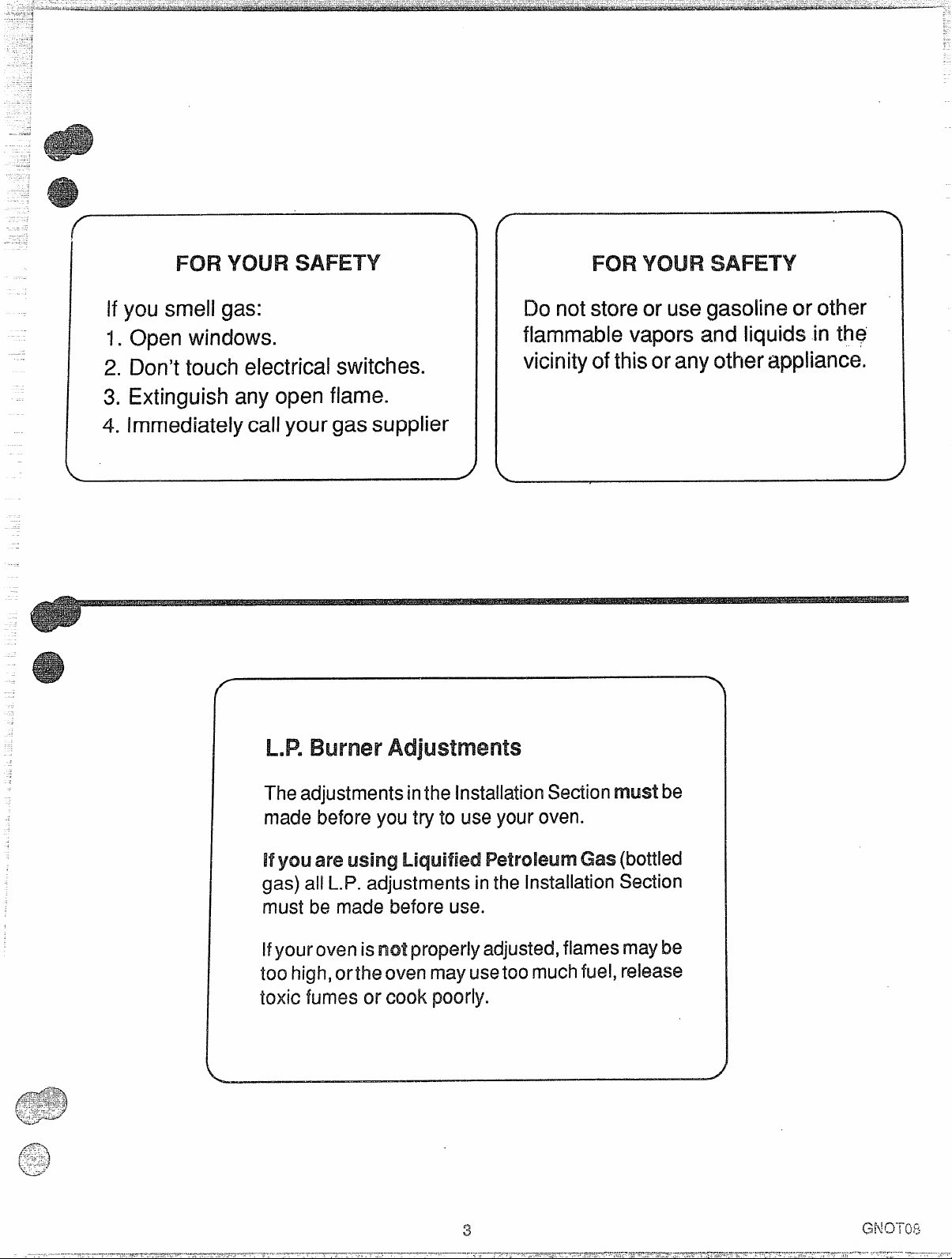
IfyoL4smell gas:
1.Open windows.
2. Don’t touch electrical switches.
3 Extinguishany open flame.
4. Immediatelycallyour gassupplier
<
M?
Dorid store or usegasoline orother
flammable vapors and liquids in the
vicinityofthisoranyotherappliance.
/
The adjustments inthe Installation Section mwst b
mabefy t t u
Hyou areWmMJ Gas (bottled
gas) all LJ? adjustments inthe Installation Section
must be made
Hyow own isnot properly adjusted, flames maybe
too high,orthe oven may usetoo much fuel, release
toxic fumes or cook poorly.
befus
ov
Page 4
the WM?.
.
—
TOOL iLKiin-
1/8” drill bit
1.
Electric or hand drill
2.
Flat bladed screwdriver
3.
No.
4.
5.
6.
7.
8.
9.
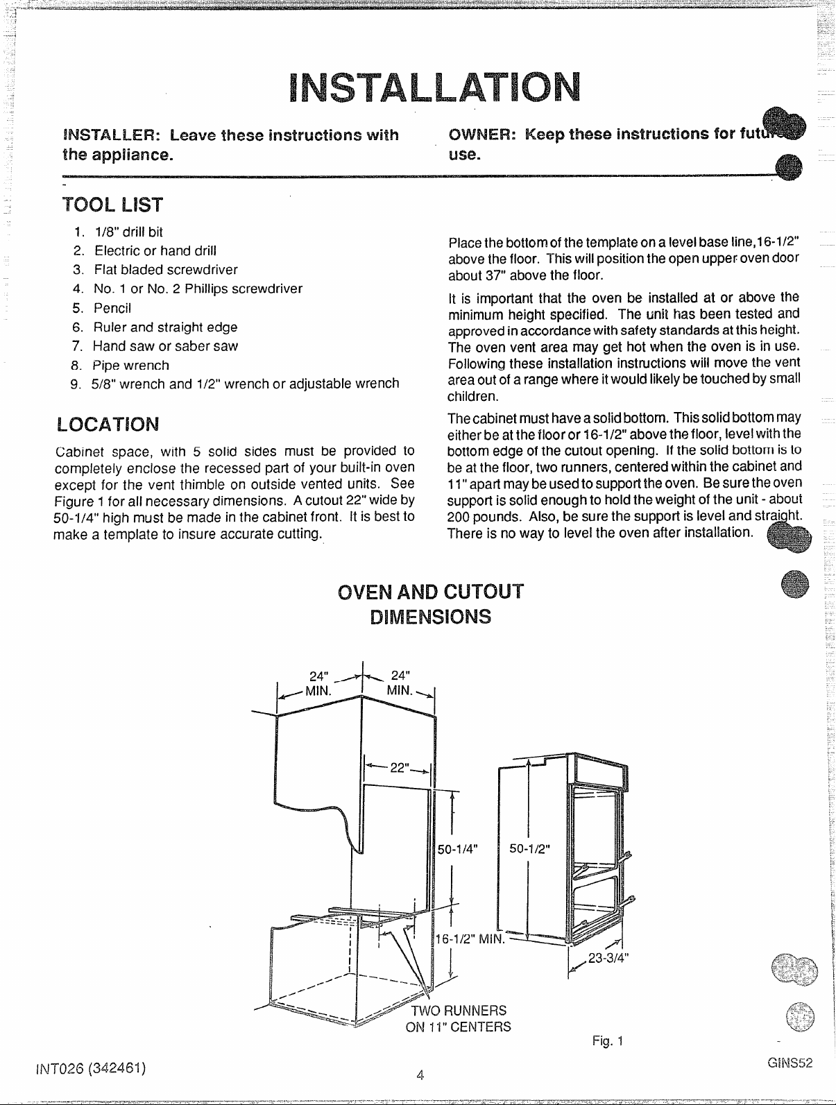
Cabinet space, with 5 solid sides must be provided to
completely enclose the recessed part of your built-in oven
except for the vent thimble on outside vented units. See
Figure ~for all necessary dimensions. A cutout 22’’wide by
50-1/4” high must be made in the cabinet front. His best to
make a template to insure accurate cutting.
1 or No. 2 Phillips screwdriver
Pencil
Ruler and straight edge
Hand saw or saber saw
Pipe wrench
5/8” wrench and 1/2” wrench or adjustable wrench
Placethebotlornof thetemplateona levelbase line,16-1/2°
abovethe floor. Thiswill positionthe open upper ovendoor
about37” abovethe floor.
It is important that the oven be installed at or above the
minimum height specified. The uni2has been tested and
approvedinaccordancewith safetystandardsatthis height.
The oven vent area may get hot when the oven is in use.
Following these installation instructions wiil move the vent
areaout of a rangewhere itwould likelybetouched bysmall
children.
Thecabinetmusthaveasolidbottom. Thissolictbottommay
eitherbe atthe floor or 16-1/2”abovethefloor, levelwiththe
bot!om edge of the cutout opening. If the solid bottom isto
beat the floor, two runners,centered within the cabinet and
11“apartmaybeusedto supporttheoven. Besuretheoven
support is solid enoughto holdthe weight of the unit - about
200pounds. Also, be surethe supportis level and stra~ht.
There is no way to levelthe oven after installation.
I (
23-3/4”
k
Fig.1
~
G
Page 5

Checkwith your local utilitiesfor electricalcodes that apply
.7
If there are no local codes, the National
e,ANS1/NFPANo.70-! 987mustbefollowed,
copy by writing:
National Fire ProtectionAssociation
Batterymarch Park
Quincy, MA 02269
An adequate electrical supply and outlet must be usedto
operatethe electricalpartsof your oven. Theovencordhas
a three prong plug and must be used with a properly
groundedthree hole outlet with standard 120volt, 60Hertz
AC household current.
Installthe electrical outlet belowthe ovenon the rightside.
Itshouldbe easily reachedthrough cabinetdoors belowthe
oven. See Figure 5.
The preferred method of electrical hook-up is shown in Fig.
2. Ifyou do not have agrounded (three hole)outlet, havea
qualified electrician change your old outlet or install a new
one.
Agrounding adapter plug maybe usedtoconvert atwo hole
outlet to a three hole outlet until a grounded outlet can be
installed. See Figure 3. This should bedoneonly temporarily and only if the two hole outlet is properly polarized and
grounded. Have a qualified electrician test the outlet to be
sure it meets all requirements.
p unplug the oven cord before making any electri-
cal repairs to the oven.
When unplugging the oven,
waysgrasp the plug, never the cord. Never use an
tension cord to connect the oven to the electrical
supply.
Do not under any circumstances cut or
removegroundingprongfromovencord.
Failure to provide proper Polarization
may create a hazardous condition.
P W G P
P P
G R
I
Y
& ,——”—.-.—.-.,. .. . .
P R
P G
M E
/
R e
P
M
S
FIG.3
TEMPCWL4RYMEWKXI
.r-..uc
GAS
cm operatethe burners of this oven
when using LP. (bottled) gas before
converting the pressure regulator and
bur’rw?f’orifices for M. gas usage.
You must follow local codes when installing built-in
oven. Check with your local utilities for codes and ordinancesthat applyin your area. If there are no loca!codes,
you must follow the National Fuel Gas Code ANSl/Z223.11984 2nd Addenda Z223.t2-1987, You can get a copy by
writing:
American Gas Association
1515Wilson Boulevard
Arlington (Rosslyn),VA 22209
Iftheoven isto be installedinamobilehome,the installation
mustconform to the !vlanufacturedHomeConstruction and
Safety Standard, Titie 24CFR,parl 3280(formerlythe Federal Standard for Mobile Home Construction and Safety,
Title24,HUDpart280)or,when notapplicable,the standard
for Manufactured f-tome installations 1982 (Manufactured
Home Sites, Communities and Set-ups) AMY A225-l-
1984,orwith localcodes. You canget acopy of the Federal
Standard by writing:
Office of Mobile Home Standards
HUD Building
451 7th Street, S.W.
Washington, D.C. 24010
Thegas supply mustbeshutoff beforeremovinganoldoven
andstayoff until the hookup of the newoven isfinished. You
should know where your main gas shut off valve is located.
Never reuse an old connector when a new
oven.
Besure nostrain isput onthe connecting line assembly. To
prevent gas leaks, put a pipe joint compound, which resists
the action of L.P. gas, on the male (outside) threads only.
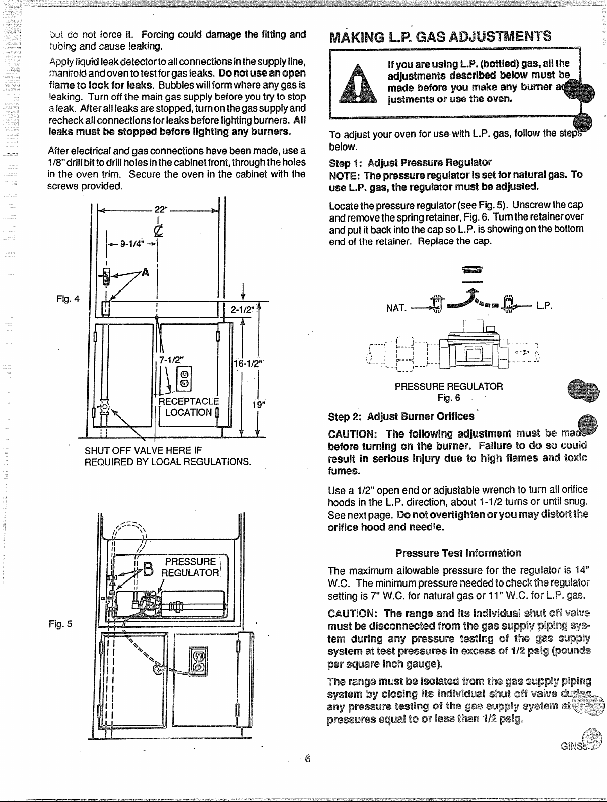
Usel/2’’ gas inlet pipe. The hok?forthe gas inlet pipe shoulci
be 9-1/4” to the left of the center line of the cabinel (see
Figure 4) and 23” behind the front surface of the cabinet.
Connect a 1/2” coupling to the inlet pipe. The top of the
coupling should be about 2-1/2” above the bottom edge of
the cutout opening (see Figure 4). Before you put the oven
into the cabinet opening, connect the 1/2” reducer shut-off
valve to the coupling (see point A in Figure 4). This valve is
supplied with the oven and is wire-tied to
Putthe oven intothe cabinet. NOTE: The oven/broiler door
may be removed before inserting the oven
lessen the weight. See the kwtructkmsintheCleaningand
Care section of the Owners Manual for removing the door.
/
;
When the oven is in place, remove the hookup and adjustment access covers at the lower oven back (Figure 5).
Reach through the access opening and connect tlw oven
tubing to the reducer shutoff valve (see point Elin Figure 5).
Usea5/8’’wrenchtoturn the fitting.
5
backd unit.
intothe(x?Mwtto
Page 6
oui dc not force it. Forcing could damage the fitting and
t~~~ngand cause
liquid k?akdetectorto allconnectionsinthesupplyiine$
manifoldandoventotestfor gasleaks. DOnot
fkwnet~ look for leaks. Bubbleswi[lformwhere anygasis
leaking.
T o m gassupplybeforeyoutrytostop
kakin~.
aleak.Af%erallleaksarestopped,tl!rnonthegassupplyand
recheckallconnectionsforleaksbeforelightingburners.M
leaksmust be before any burners.
After
electrical and gasconnectionshavebeenmade,usea
l/13*’driHbittodrillholesinthe cabinetfront,
in the oven trim. Secure the oven in the cabinet with the
screws
LJ?
To adjustyourovenforusewithL.P. f
below.
Locatethepresmm reg.dator(seeFig.5). Unscrewthecap
andremovethespringretainer,Fig.6.Turntheretairwover
andputitbackintothecapsoL.P,isshowingonthebottom
endoftheretainer. Replacethecap.
I
1
A’
Fig.4
,
71
7-1/2W
:
1[).0
RECEPTACL
SHUTOFF VALVEHEREIF
RK?UIR13JBYLOCALREGULATIONS.
+
2-1/2?
TT
j
1
19;
L
1 I
,. --.,
-1
~ ..-..,- -
~==={---;-
,
I
I
,;
:/ ,
W
.4
I
I
B==={ ‘
&
_
4
PRESSUREREGIJLATOR
Fig.6 ~
step2: Adjust EwTiw CMifkx?s’
m?
befcm tw’nh’lgcmthe M!i’rwiF%ih.n todo
result inseriousrlriywy(we WI high imdiWn-4k
be ma
nmws.
Usea 1/2”openendor adjustablewrenchto turn allorifice
hoodsinthe L.P.direction,about1-1/2turnsor untilsnug.
Seenextpage.Do
orifice hood
and needle.
Fwess,nreTest
Fig.5
The maximumallowablep k
V
The r p n t r
s
,
o
W.G.for n g V
Page 7
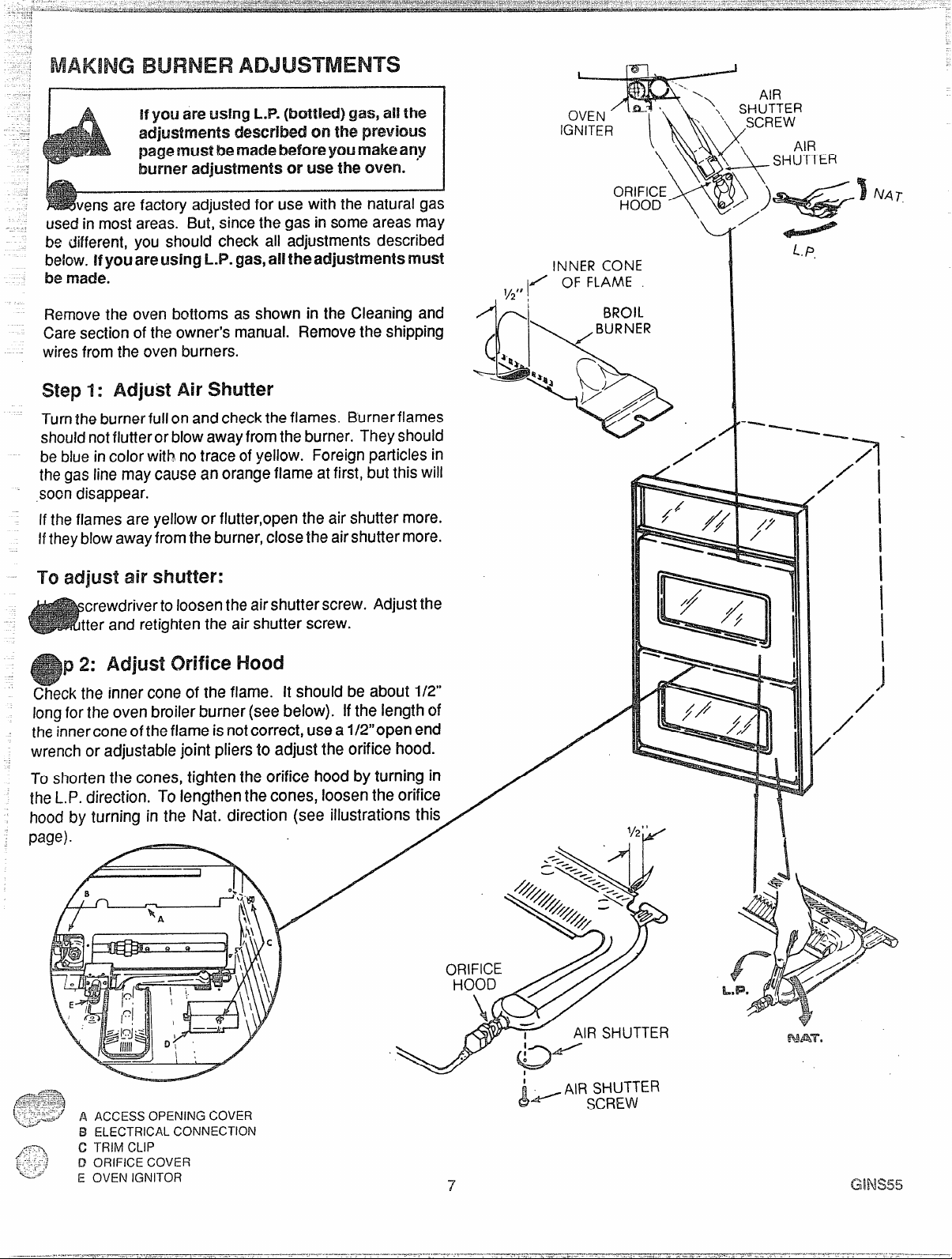
,
1
used But, since the gas in some areas may
be different, you should check all adjustments described
below.Ifyouareusing L.P.
be
made.
Removethe oven bottoms as shown in the Cleaning am!
Caresection of the
w f the oven burners.
step 1: Air Shutier
Turnthe burnerfull on and checkthe flames. Burnerflames
shouldnotfiutteror blow awayfrom the burner. Theyshould
bebJueincolor with notrace of yellow. Foreign particles in
the gas line may cause an orange flame atfirst, butthis will
,soondisappear.
Ifthe flames are yellow or flutter,open the air shutter more.
Htheyblow awayfrom the burner, close the airshutter more.
TO adjust air
crewdriverto loosenthe airshutterscrew. Adjust the
‘(
I
1
\
.
tter and retighten the airshutter screw.
2: Adjust orificemod
p
Checkthe inner coneof the flame. It should be about 1/2”
l forthe oven broiler burner (seebelow). Ifthe length of
!heinnercone ofthe flame isnotcorrect, use a l/2’’open end
wench or adjustable joint pliers to adjust the orifice hood.
I_oshorten the cones, tighten the orifice hood by turning in
heI-P. direction.
lood by turning in the Nat. direction (see illustrations this
o m Removethe shipping
ToIengthen the cones, loosen the orifice
gas,a!ltheadjmtmnts mm!
INNERCONE
1X FLAME
1/2”,
c
-+’ ,,4 ‘~
1!
a
L
.: .
\
/
L
L.P.
IN?OIL
B
LA) //y
I
I
I
I
1
I
)
/
/
/
1/2
“9’)”- “
A O C
E C
T C
O C
O I
OJJI(J
‘J
AIRSHUTTER
- AIR SHUTTER
L
d--- sc~~w
f?wwr.
Page 8

u
Keep this book for later use.
Besure
your oven is installedand grounded prop-
erly by a qualified technician.
keep the oven area clear and free from
things that will bum, gasoline and otherflammable
vapors and liquids.
Always change oven rack positions while oven is
coo!.
broiling,alwaystakethe broiler panoutofthe
ovenandclean it. Leftovergrease inthe broilerpan
can catch on fire next time you use the pan.
Ahnmysuse dry pot holders when removing pans
from the oven.
Moist or damp potholders can
cause steam burns.
Always usecare when opening oven door. Let hot
air and steam out before moving food.
Always follow cleaning instructions in this book.
Teach children notto playwith oven controls orany
other part of the oven.
I r or replaceany parl of the
unlessinstructionsaregiveninthis book.Al! d
work should be done by a ski!ledtechnician.
Never heat unopened foodcontainers. Pressu
build up may
m container burst and caus~
injury.
Never leave jars or cans of fat or drippings near
t ovNeMgrease buildup onycwroven.
You can keep grease fires from starting if you
clean up grease and spills after each oven use.
Never use aluminum foil to line oven bottoms.
Improper use of foil could start a fire and cause
incomplete combustion.
Never block the flow of combustion and ventila-
tion air through oven vents.
Never try to move a pan of hot fat, especially a
deep fat fryer. Wait until the fat has cooled.
Never leave children alone or unattended where
an oven k3in use.
Never use your oven for warming or heating a
room. Such use can be dangerous and c
damage oven parts.
Never wear loose fitting or hanging clotheswh
using your oven. Such clothes could catch f
and cause serious injury.
Never use a towel or other bulky cloth as a pot
holder. Such cloths could catch fire on a burner.
Never store things in an oven.
Neverfusewater cma grease f will cmly 1.close oven Ckmr and t u
Spu?ad m m
2. Hfire’ MMmNM?s, soda On the
f oruse adry chemical -kX3rn$29 t
!!30rid t W move‘me park
The California Safe Drinking Water and Toxic 1
Act requires the Governor of California to publish a list of
substances
businessestowarn custonwrsofpotentialexposuretosuch
substances.Gasappliancescan causeminorexposureto
threeof thesesubstances,namelybenzene,forrmakkhyde
knowntoMestatetoczwseCarxerandr
andsoot,causedprimarilybytheincompletecombustionof
naturalgasorL.P.fuels.
bya bluish
pkte combustion.Expc&m3to these substancescf$~~}3
minimizedfuriherby ventingwithan openwindoworN%+$9
a ventilationfanor hood.
r a y f!arne,willminimizeirKgn-
Properlyadjustedranges,indicated
‘“-’~
<:;;2’.
,,-Y;,j
;J
L_
8
Page 9

,
;
-
% =%2?-
-
.
,-A.
Themodel
and serial number @
yourfWl!m!sfCW’?dcma
tag, the upper
door, ‘on the left
f the front WM’lx?.
the numbers Into
space on page 2 of
manual.
1.
2.
3.
4.
5.
.
o Light s
LowerOven (Xntmi
Oven Vent (area may get
130tduringoven use: Do not
block vent)
Electronic Oven Co@rol
BroilPanandGrid
Ftemvabk?CWerIRacks
6.
(
7.
FWmvab!eOvenBottom
RemovableOvenDoor
8.
Lower Oven
9.
(9
and
/
Whenvou turn the upper or lower oven on, one of the glow
barign~terbeginsto %at. Whenth@igniter is hot enough, in
about1
minute,the glassflowsintotheburrterandisignited.
Theigniterglowsbrightorangewhen hot. Itcyclesonand
offwiththethermostatandwillglowwhenevertheburneris
on.
A Du~i~Q~PQ~~~f~~~~~~~~~~~f~~’~~~n~’ ‘
CIVEN
Whentheovenison,heatedairrnovesthroughavent under
thecontrolpanel. This hotairmaymakecontrolpanelarea
ho!.
See the following pages.
Toi3ake:
1.Turn LowerOven
~ d t
2. WhenfinishedturnLowerOvenControlto OFF. The
lowerovencanbeusedwhilethe upperovenis on. You
cannotbroilinthe loweroven
9
GBlFc15
Page 10

Range
—-—.
TIME
Shows the time of day, the times you set for
maticovenoperationsor timer,oventempera-
ture
SET KIWX3- Turn to set times and temperatures.
2.
FUNCTION INDICATORS
3.
whether oven isbaking or broiling and whether you
are using the timer.
ALJTCNMATICOVEN INDICATORS-Show whether
4.
an automatic oven operation that will start later
(delay) iscurrently programmed and whether oven
or stop time is being shown.
OVEN TIME - Pushbefore setting length of time the
5.
oven will be on (for automatic oven operations).
TEMPERATURE DISPLAY WINDOW -
or broil settings you have selected.
- Light up to show
o
auto-
4
TIMER - Push
8.
BAKE - Push before settingtemperature.
C - C e e c
10.
t
you’ve made a mistake in programming.
EIRCNL- Pushbeforeselectingbroil setting.
It.
3
0
b s a t
oven off orto clear everything”
S
STOP TIME - Push before selecting the time
6.
want the oven to turn off
o
C -
7’.
of day into the
Push before setting clock or to bring time
l DISPLAY WINDOW.
C
B
a
C S O
T
\
10
r
PUSH
B
T
T
J
Page 11

-:.:
.............. ... . .. ......... .. . .
J
.
TO OR
2
d w I r
A t w s o r
OVEN OFF’
3 PUSH
n
)
ON OFT
[
/
i
— — —
n
T
Whencook e a s
wiil t
C
C S
l
O
w
n
L
. (
C
A
.
1
~
?
I
Y =’
;
——. —
C
T
W s r a s
o w t o
I
O
S
n
T
1 f
1
PUSH
(s”
—
w c
TOSET LENGTH
C
OR
Attention T s p
1.
p e s a
t t A
u y s a teCANCEL.
TURNTOSET
T
. . . .-
~\
PUSH
1
s HOLD
o“
3 S C
NOTE:T’tIetimer is a and will rm$operate
the oven.
You mayrecall f p b o
f
2. Funciion
o r f
s
E s t a p
~ b
& p
s a
Page 12

-------
~:..:,,,,..,..
,... .. ......
...,.
. ,..... . ..
“
;.;..
..:..::. . . .
... . ......
...
e
Alwaysfollow recipecarefully.
Measureingredientsproperly.
Use proper pan placement.
Let the oven preheat thoroughly before
Cookingbaked products.Allow
10-d5 mtin-
utespreheattime.
Avoidopening the door too often to check
the food during bakingas heat will be lost.
Thismay resultinpoorbakingresults.
Cakes, cookies, muffins,and quick breads
should be baked in shinypans— to reflect
the heat
— becausetheyshouldhavea light
golden crust. Yeast breads and pie crusts
shoul~ be bakedin glassor dull (non-shiny
pans)
— to absorbthe heat — be~au~etheY
shouldhavea brown,crispcrust.
@
Placepans on the ovenrackswith 1Vi- 2“ of
space cm all sides of each pan. Avoid
air
overcrowdingthe oven.
@
Pans too close to each other, to oven walls
or to the oven bottom block the free movement of air. Improper air movement causes
uneven browning and cooking.
2 cake hyers
Q
baking should be done on the second
shelf posRiOnfrom the bottom. When baking
several items, use two shelves placed on the
second and fourth rack positiOnSfrom the
bottom of the oven. stagger pans so that no
pan is directly above another. E3akf3angel
f(x)d cakes on the first shelf p(xithm from
the of the oven.
Oven temperatures should be reduced 25
degrees below recommendedtemperatures
if you usedark pansor ovenproofglass.
There may be some odor Whenthe oven is
first used. This is caused by the heating of
ne-wpartsand insulation.
@
Do not cover the oven bottom or an entire
oven rack with foil. The foil can block nor-
mal heat flow, cause cooking failures, and
damage the oven interior.
12
Page 13

WHEN
3
Most f b 1 S S
LO B s a e b
irq of foods that should be c the well done
s ( t porkc p
@ Broiling is cooking by direct heat from the broil
burner.Tendercutsof meator marinatedmeatshould
be selected for broiling. For best resuRssteaksand
chopsshouldbeat least%“thick.
@After placing food on the broiler pan, put the pan on
n oven rack in the proper rack position.The recom-
mended rackpositionand cookingtime can be found
inthe chartat right.
@The closer the food is to the broil burner, the faster
the meat brownson the outside, yet stays red to pink
in the center. Moving the meat farther away from the
burner letsthe meat cook to the center while browning outside. Side one should be
longerthan sidetwo.
* Your oven door be
@
rangefor broiling.They aredesignedfor proper
the broiler pan and gridthat came with your
1
TO
B 2
6
c m
while
d
and liquids andhelp preventspatter,smoke
or fire.
e DO ~of when broiling. Preheating
m
thermostat to cycle the broil burner off and on.
For even broiling on both sides, start the food on a
cold
p
Q T t ~ i
the fatty edges to keep the meatfrom CWhI$J
A-F~_
,..g.e-=..-=---
~~~~~;=k juiciness, salt the first side just before
turning the meat.
,s-7) sw-!hg.
f- -.-l
!. -
. ,.*
of fat from steaksand ChOpS.S!it
Salt the stxxmd side just befme
E3rushchicken and fish with butter several times as
they broil.When broilingfish, greasethe grid to keep
itfrom stickingand broilwith skinsidedown. It isnot
necessaryto turnfish.
Neverleavea soiledbroiler pan in the range. Grease
in the pan may smokeor burnthe nexttime the oven
isused.
Be sureyou the correct for
QXNa greasefire.see the
Do nd txww the Mob grid foil.
drainaged hot fatmay txwse a Bw’$mw
PO(M’
me.
If a firestarts,dose oven door and turn
mnhds M. M conhues, throw baking
soda the me.Dcl notputwater the
me.
Rack
Fod
Position
4=
1=!LOwest
Steak - 1“ Thick
Rare
Medium
Well Done
Ground Beef Patties
Medium
Wel! Done
Lamb Chosm- 1“Thick ] 3
Pork Chops - 1“ Thick
Pork Shoulder Steaks
l-lamSlice - fl”Thick
Fish (Fillets)
Chicken (Halves)
Frankfurters
Sandwiches
This chart is a !2y37eralguide. The size, weight., tl7ick-
4
3
3
3
3
3
3
3
3
1
3
2
I
riess, and starti~g cd the food as well as
your own personal preference will affect the
time. Times in the chart are based on the food being at
Totai
I
1
10-12
14”16
20-22
11-13
13-15
16-20
20-25
15-20
14-16
10-15
40-60
10-15
6-10’
I
1
Time
I
1
Page 14

Ame
-
314cup margarine,softened
7cup sugar
2eggs
1cup sour cream
2 cups all-purpose flour
1teaspoonbaking powder
1teaspoonsoda
1/2teaspoonsalt
1teaspoonnutmeg
3/4 cup light brown sugar
1/2cup chopped pecans
1teaspooncinnamon
Creammargarine andsugaruntil light andfluffy. Add eggsand
saltand nutmeg. Add to batter and mix well. Pour batterinto gr
Combine brown sugar, pecans and cinnamon; mix well. Sprinkle one half of this mixture over cake batter;swirl mixture
through batter.Sprinkle remaining one half mixture evfmlyovercake batter.
c w C f b p s
‘ f x x b
Cover and chill overnight.
toothpick.
A delicious quick-to-make hearty stew that.will feed a crowd or feed the family. Refrigerate or freeze the remainder for
another day.
7-10 oz. can barbecue beef
7-70 oz. can barbecue pork
1-24 oz. can Brunswick stew
1-5 oz. can boneless chicken
1-12 oz. can vacuum packed corn niblets
7-76 oz. can baby lima beans, drained
2-16 oz. cans stewed tomatoes
; - J~I/~Oz.can sliced okra, drained
U and bake in preheated 350°F oven for 35 to 45 minutes or until caketests done with
2-10 oz. pkg. frozen chopped broccoli
1cup mayonnaise
Ycup sharp cheddar cheese,grated
2 eggs, beaten slightly
1can cream of mushroom soup
2 tablespoons chopped onion
1cup cheese cracker crumbs
Preheat oven to 375°F.Cook broccoli according to package directions; drain.
Mix with other ingredients. Pour into greased two (2) quart casserole.Sprinkle
with cheese cracker crumbs. Bakeat 375°F for 20-25minutes.
Elrainokra and lima beans. Add to all other ingredients in 4quart
@m.Heat on medium to serving temperature.
P
Page 15

1/2C mtwganm
CL@chopped gpwmpepper
cup chopped onion
3 eggs, well beaten
17oz. can cream style corn
17oz. can whole
muffin mix
7 cheddar chcmw?,shredded
Preheatoven to
350°F.$13uk?green peppers and onion in margarine; combine
with remaining ingredients except cheese. Pour into greased two (2) quart casserole; sprinkle with cheeseand bake45-55minutes in 350°F oven+.Letstand 5
minutes before serving.
(M@my:Illinois
Cooperative Extension Homemakers
squaresserni-sw@ chocolate
1stick margarine
1cup sugar
1/4cup flour
2 eggs
1tsp. vanilla
Dash salt
I%CUpchoppedpecans
Frozen 9“ pie shell
W oven to 350*F. Melt chocolate and margarine. Add othe~
ingredients to melted mixture. Pour into unbaked pie sheil and
bake 35-40 minutes or until pie appears set. Serve warm with ice
cream or whipped cream.
w
.
1-20 oz.
a pie filling
1/2 cup sugar
1-9 oz. box white cake mix (1 layer size)
1stick margarine, melted
1/2 cup chopped pecans
Preheat oven to 350°F. Place in layers in greased 9“ or 10” square baking dish:
apples, sugar, dry cake mix. Pour melted margarine over top of cake mix. Bake
at 350° F for 35 minutes. Sprinkle with pecans. Continue baking 15 minutes.
w
Serve
Page 16

..=
.-
..... .. ........ .......... .............
...
.-
Onthefollowing Pac&, the removable pals cm
your oven are shown. Referto those pages
when cleaning your range.
~ w a m d a c
PART
Control pane{ and knobs
Glassoven cfoor/wincfQw(some
models)
Oven finishes:
Continuous-cleaning (some
models)
Standard porcelain enameled
ovens, porcelain enameled
(smooth) areas of continuous-
cieaning ovens, broiler comPa~ment, broiler pan
CLEANINGMATEFtM-S
Detergent,warmwater,softcloth
Glasscleanerandpapertowels
See special instructionson previous Page”
Detergent,warmwater, scouring
pad or soapfilled steel WOOIpad
or non-aerosol (brush-on)o~en
cleaner
are safe to usecmall cleanable parts of your
range, /+[1purpose cleaners,such as F%rNastik@,can also be used. Do not use metal sw3uring pads, exceptwhere recommended.
Donotuse
foreasiercleaning.
Removestubbornsoilwithpasteof baking
sodaandwater. Donotuseabrasivecleaners. Rinsethoroughly.
Rinsethoroughly aftercleaning.Whenusing
ovencleaneroncontinuous-cleaningovens
besureto keep it awayfromthe continuOuscleaning finish. Oven cleanerswili damage
the continuous-cieanin9 finish. Oven bottom can be removed for easier cieaning.
Remove oven bottom of continuous-Giean-
ing ovens if cieaning it with oven cieaner.
abrasivecleaner~.Knobspul!off
--
O Racks (and guides on
some models)
Detergent, warm water and
scouring pad or soap tilled steel
wool pad
Removefrom ovento clean. Drythoroughiy.
Page 17

HOLES
.1
1-
ecarefulnot toscrakh the ovenfinish when insta$!ing
r removing oven racks.
“i-clmm!!:
.1. PM thepegsontheendofthe rackguideintotheholes
intheovenback.
Lockthe front hook in the slot inthe oven side.
2.
3.
Set the raised back edge of the oven rackson a pair
of rackguides sothe hooksatthe sides ofthe rackrun
underneaththe rackguides.
4.
Pushthe rack in until you reach the bump inthe rack,
Ihen lift the front ofthe racka bil and push the rackall
the way in.
r
To
,Pullthe oven rack out, then
2. Lift thefront ofthe rackguideto unhookitfromtheoven
pky
*
11
*/%””” “-‘ II
:
/
f
BUMP
/
the door.
2. Lowerthe doortothefullyopenpositionandpushthe
r tabs down (see fig. A).
Removetheovenbottomfor easier cleaning.
Becarefulnotto scratchthe ovenfinishwhen removing or
installing oven bottom,
remove:
-i-cl
1. F oven racks and guides (see above).
2. Lift the front of the oven bottom enough to clear the
front frame, then pull OUI.
To replace:
~ Slidethe oven bottominto the oven so thatthe back
*%*:1 .
.-----.=—~>-..—=
i----!=---.-,--2
.,,
,.-=-”-..d—>w-
~~+;-%
(
[~:% 2. LowerihefrOntof theov@nbo~omin?oPlacebehir]dthe
. .
edgeoftheovenbottomresisonthe
oven wall.
..
ridge inthe back
C ‘II
Fig.
I%(X=JTFRAME
//
\%’&.
-“/
l%. D I
1
.
I
Page 18

Do fnog wan bulb. notWdl bulbwith wet
hands. Newerwipemen light areawith wetcloth.
M& touch the electrically live metal collar on the bulb
when replacing it.
Replacethe bulb with a 40 watt, appliance bulb. An
appfiance b is’smailer than a standard 40 watt household bulb“andis made to withstand high oven tempera-
tures and havea much longer bulb life.
18
cHvmn-02
Page 19

%aw?m’ie t cmforW
0
e (Mm burnersdo notwork.
(Ms supplynotconnectedor
notturnedon. If usingM.
gas,tankmaybeempty
0
Appliance not properly
groundedor polarized. This
canaffectsparkignition.
e
Controls
9
Burnersnotadjustedproperly
notsetcorrectly
“ (Meckthe reducerstwt-offvalvearid~he
gassupplyshut-offvalvetoIX!surethey
areopen(seeinstallationsection)
IfusingL.P. gas; isthereanygas inthe
L.P. tank?
G Checkinstallationsectioninthisrn~nual.
e Check operatinginstructionsin this
manual.
o Foodsdo notbakeproperly
o F b p
~ O smokes
Oven not preheated long
enough
Improperrackor pan place-
ment
Ovenventblockedorcovered
Improperuseoffoil
Impropertemperaturesetting
forutensilused
Recipenotfollowed
Usingimpropercookware
o Improperrackplacement
o (Menpreheated
~ Improperutensilused
o Improperbroilingtime
~ Dirtyoven
Besureto preheat.
10minutesbelow350degrees
IS minutesabove350degrees
Maintain
unikmnairspace arotmdp
andutensils; seeovencookingsection.
Besureovenventis notMocked
Foilusenotrecommended. Reducetemperature25degreesforg~a$$
or dulVdarkenedpans.
!srecipetestedandreliable?
Seeovencookingsection.
Check broil
section.
Do not preheat
pan placement in broiling
whenbroiling.
Use broiler pan and grid suppliedwith
range.
Checkbroilingchartin broilingsection.
o (Meekfor heavyspiliover.
———
Broilerpanful[ofgreaseleflin
o
oven
~ clean panandgrid aftereachuse.
s Check witch setting.
Checkor replace twe w%w’@
Q
care
Page 20

H )’(3LI service
To obtain service, see your warranty
on the backpage of this book.
We’re proud of our service and want
youto be pleased. If for somereason
youarenot happywith the serviceyou
receive,here arethree stepsto follow
for further help.
FIRST, contact the people who serv-
icedyour appliance. Explainwhy you
arenotpleased. Inmost cases, this
will solvethe problem.
NEXT,ifyouarestill not pleased,write
ail the details-including your phone
number-to:
Manager, Consumer Relations
RCA
Appliance Park
Louisville, Kentucky 40225
F\NALLY, if your problem is still not
resolved,write:
Major Appliance
Consumer Action Panel
20 North VVacker12rive
Chicago,
~ 60606
20
Page 21

I
yoursalessliporcxmcekxicheckto
!!s FULL
f%!’
fxpurchase,we provide,
freeofcharge,partsandservice
laborinyourtmrrwto repairor
replace of theoventhat
failsbecauseofa manufacturing
defect.
Thiswarrantyisextendedtothe
originalpurchaserandanyswceed-
ingownerforproductspurchasedfor
ordinaryhomeuseinthe48 main-
landstates,HawaiiandWashington,
DC. InAlaskathewarrantyisthe
sameexceptthatitis LM!TE~
becauseyoumustpaytoshipthe
producttotheserviceshop or for the
servicetechnician’stravelcoststo
yourhome.
o Servicetripsto t
Ifyouthenhaveanyquestions
about theproduct,
pleasecontactyourdealerm our
I’xmlw.
~ improperinstallation.
Ifyouhavean installation
contact your dealer or instailer. You
.,
are responsiblefor providing adequate e9ectri6al,plumbing and other
connecting facilities.
me year km the date of
p
c
rna!m’idm
Affairsofficeataddress
problem,
WeatRCAstrivetoprovidethehighestquality
p s
Therefore,wehavedesignatedGE
CONSUMER
theserviceindustry,to
service needs. Should your appliance
need service,during the warranty
SEFWKX, aleaderin
Milt your
periodorbeyond,lookintheWhiteor
Yellowpages of
yourtelephone
directoryforGECONSUMERSEFWKX or anAUTHORIZEDRCA
ANCE SERVICER.
APPLl-
Q Replacementofhousefusesor
resettingof circuitbreakers.
~
Failureoftheproductif it isused
forotherthanitsintendedpurposeor
usedcommercially.
0 Damageto productcausedby
accident,fire,floodsor acfsofGod.
WARRANTOR K N(3T RESPCNSH3LEFOR CONSECWENTMd-
DAMAQES.
4
4
Somestatesdonotallowths exclusionorlimitationofincidentalor consequentialdamages,sothe above
limitationorexclusionmaynotapplyto you. Thiswarrantygivesyouspecificlegalrights,andyoumayalsoham
otherrightswhich fromstatetostate. Toknowwhatyourlegalrightsareinyour state,
consultyourlocalor stateconsumer
a o oryour state’sAttorneyGeneral.
 Loading...