

Page 1
....,
.”- —..—— ..—
.——.~
.—
--,:
.. ...—-..—.--—.—---..—-..—.——.
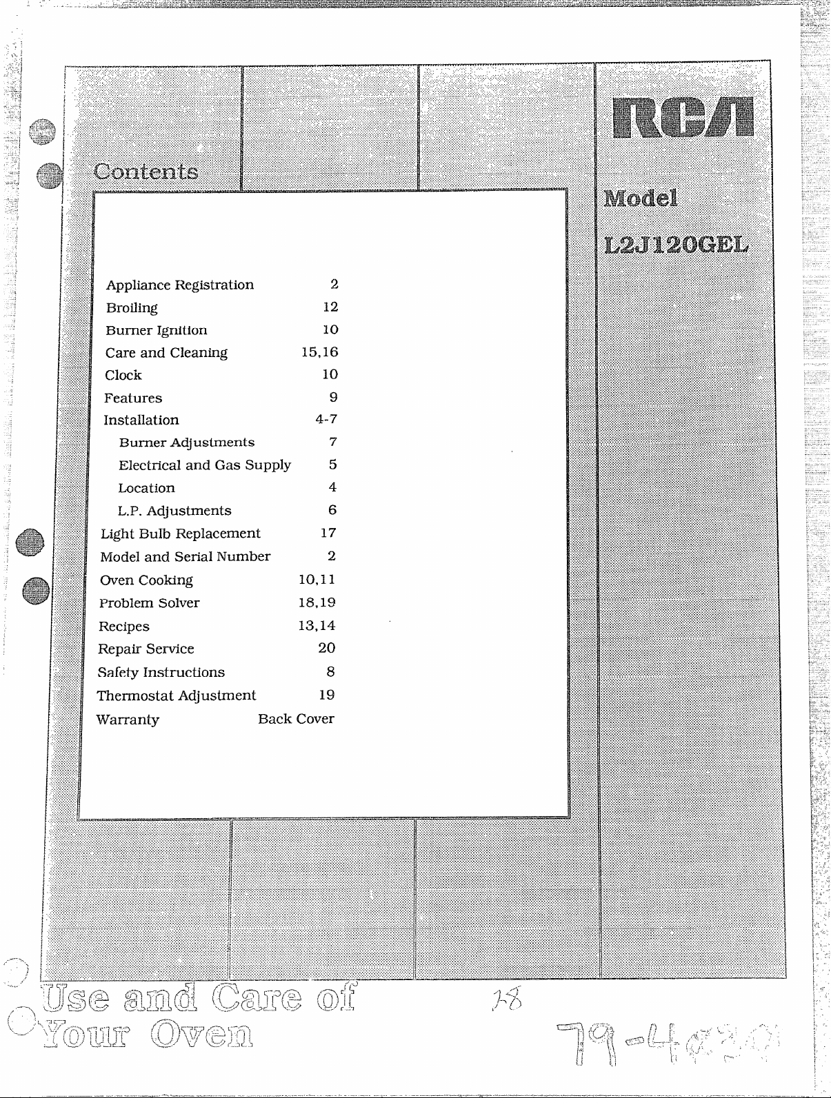
Appliance Registration
Broiling
Burner Ignition
Care and Cleaning
ChCk
Features
Installation
IXnmerAdjustments
Electrical and Gas Supply
Location
LOP.Adjustments
Light Bulb Replacement
10
4-7
9
7
5
4
6
Model and SeriaI Number
Oven Cooking
Problem Solver
Recipes
Repair Service
Safety Instructions
Thermostat Adjustment
10,11
18,19
13,14
2
8
19
Back Cover
,-----
.....
,<
Page 2
Rethbocar
mo
If isintendedto help you operateand
maintain your new oven properly.
Keep it handy for answers to your
questions.
If youdon’t understandsomethingor
need more help, write (include your
phonenumber):
ConsumerAffairs
RC
AppliancePa*
Louisville,KY 40225
I y re
a daov
Immediately contact the dealer (or
builder)that soldyouthe oven.
S t a
Bey re
ser
Check the Problem Soh@r. It lists
causesof minor operating problems
that youcan correctyourself.
Wrdot moa
senwm
You’llfindthemon alabelonthefront
of Iheovenbehindthe ovenor broiler
door.
Write these numbers into the space
below.Alsowritethe numbersintothe
spaceon the warrantycardthatcame
with your oven before you send the
card in.
ModelNumber
SerialNumber
Usethese numbers in anycorrespondenceorservicecallsconcerningyour
oven.
Page 3
/
Se
yo
re
-—-.——..—.. ——.—..
—.—
\
FOR
Hy smg
qxWi
1.
Dotoeleswi
2
Extia o fl
3
4
Immec y g su
D n s o u g o o
flv a l i t
vio t o a o a
S
/
L
L
T adjui t InsSe! b
mabey t t u y o
[fa us!lJPeG (b
gaa L adji t Ins
mub m beu
I
t hio t o m u t m f
tofuo c po
o i n pradf m
3
GNOT03
Page 4
.-...—.-
.
.——.———-
-.
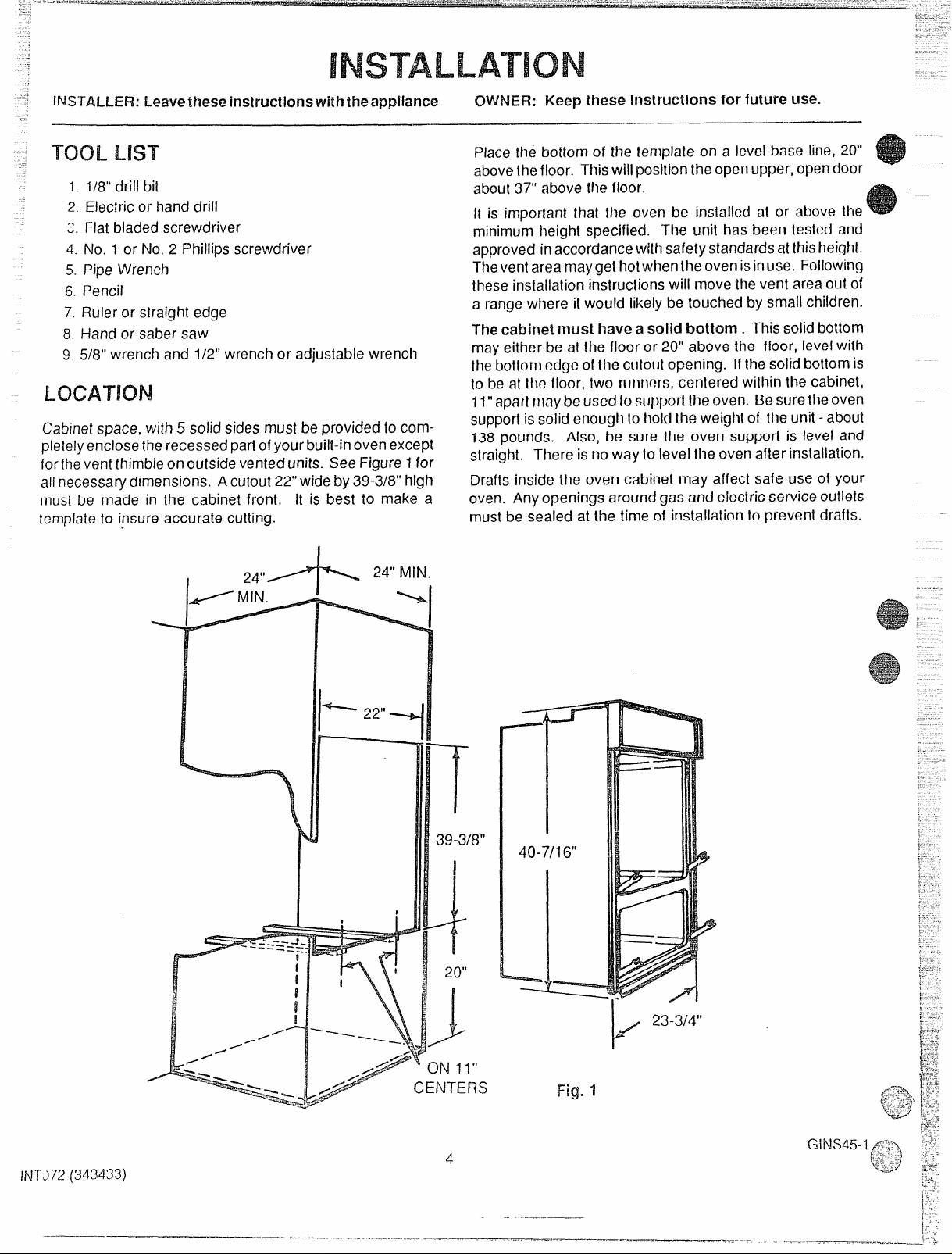
fNSTN-f&R: Leavethese instructions with theapp!lance
-I-Us-r
1.1/8”drill bil
2. Eleclric or hand drill
q Flatbladedscrewdriver
v.
4. No. 1or No. 2 Phillips screwdriver
5. Pipe Wrench
6. Pencil
7. Ruleror slraight edge
8. Hand or sabersaw
9. 5/8” wrenchand 1/2” wrenchor adjustablewrench
Cabinetspace,with 5 solidsides must beprovidedto com-
pletelyenclosethe recessedpartofyourbuilt-inovenexcept
forfhe ventthimbleonoutsidevenfedunits. See Figure1for
allnecessarydimensions. A cutout22”wideby39-3/8”high
must be made in the cabinet front. It is best to make a
templaieto insure accurate cutting.
CNNNER:Keep these instructions for future use.
Placethe bottom of the template on a level base line, 20”
abovethefloor. Thiswillpositionthe openupper,opendoor
aboul37” above the floor.
His importan! thal the oven be installed at or above the
minimu’mheight specified, The unit has been tested and
approvedinaccordancevdthsafetystandardsat thisheight.
Theventareamaygethotwhenthe ovenisinuse, Following
theseinstallation instructionswill movethevent areaout of
a rangewhere it would likelybe touched by smallchildren.
Thecabinet must have asolid bottom. Thissolidbottom
mayeither be at the floor or 20” above the floor, levelwith
thebotlornedgeofthe cuto[ltopening. If the solidbottom is
to be at thf?floor, two rllntwrs, centered within the cabinet,
11”apfitt IIIaybeusedtosupporttheoven. fl? suretile oven
supportis solid enoughtoholdtheweight of the unit -about
138pounds.
straight. There isnowayto levelthe ovenafter installation.
Drafts inside the oven cabinet may affect safe use of your
oven. Anyopenings aroundgas andelectricserviceoutlets
mustbe sealed at the time of installation to preventdrafts.
Also, be sure the oven support is level and
~ 24”MIN.
c
EfW
11“
‘ERS
23-3/4”
k
Fig. 1
IN1J72(343433)
.—————-
4
-.
Page 5

Checkwith yourioca!utilitiesfor electricalcodesthat apply
your area. Uthere are no local
lecMcaicode,
You
canget a copyby writing:
An adequate electrical supplyand outlet must be used to
operatethe electricalpartsofycwroven. Theovencordhas
a three prong plug and must be used with a properly
groundedthree hole outlet ina standard120volt, 60 cycle
AC household current. Never use an extension cord to
connectthe oven to the electricalsupply.
installthe electricaloutlet belowthe oven on the rightside.
Itshouldbe easily reachedthroughcabinet
AN!3VNFPANo.70-1987mustbefollowed.
National Fire ProtectionAssociation
13atteryrnarchPark
CMincy,MA 02269
codes,the National
doorsbelowthe
oven.SeeFigure5.
Thepreferedmethodof electricalhook-upisshowninFig.2.
If you do not have a grounded (three hole) outlet, have a
qualified electrician change
youroldoutletor installa new
one.
Agroundingadapterplugmaybe usedtoconverfatvvohole
outlet to a three hole outlet until a grounded outlet can be
installed. SeeFigure
ily andoniy if the Mo hole outlet is properly polarized and
arouncied. Have a cwalifiedelectrician test the outlet to be
meetsallrequirements.
re it
3. Thisshouldbedoneonlytemporal-
Alwaysunplugtheovencordbeforemakinganyelectrical
irs to the oven. When unplugging the oven, always
sp the plug, never
Do n under any Wcwnstancesc or
removegroundingfprcmg
Failure to provide proper polarization
thecord.
f csvencord.
may causeshock and fire hazard.
PLUGWITHGROUNDPRONG
PROPERLYPOLARIZEDAND
GROUNDEDRECEPTACLE
POIARIIZEDRECEPTACLE
PROPERLYGROUNDED
METALEYELET
o
VQ
g‘ ‘ .../
(GROUND)
RECEPTACLE
FUTE
MOUNTING
“< SCREW
141
KM
n c the+bwmm o MS oven
when using i (imttkd) gas before
the preswm$ tmcl
burngasusage.1)’Mg$l
f!arne$
Swkms injury.
You must follow local codes when installing your built-in
oven. Check with your local utilities
nanceswhichapplyin
you mustfollow the NationalFuel GasCodeANSl/Z223.11984and Addenda Z223.12-1987. You can get a copyby
writing:
Arlington (Rosslyn),VA 22209
Iftheovenisto be installedina mobilehome,the installation
mustconformto the Manufactured Home Constructionand
SafetyStandard,Title 24CFR,pad 3280 (formerlythe
eralStandardfor
Title24,HUD,Part280)or,whennotapplicable,theStandardfor ManufacturedHomeInstallations1982(Manufac-
turedHomeSites,CommunitiesandSet-ups),ANSI
1984, or with local codes.
standardsby writing.
Officeof MobileHomeStandards
Thegassupplymustbeshutoffbeforeremovingan’olcloven
andstayoffuntilthehookupofthenewovenisfinished.You
shouldknowwhereyourmaingasshutoffvalveislocated.
Neverreuseanoldconnectorwhen installinga,newoven.
Be
sure nostrain isputonthe connectinglineassembly.To
preventgasleaks,putapipejointcompound,whichresists
theactionofL.P.gas,onthe male(outside)threadsonly.
Usel/2’’gasinletpipe.Theholeforthegasinletpipeshould
be8-1/4’’totherightofthecenterlineofthecabinet.Connect
a 1/2” couplingto the inletpipe. Thetop of the ccmp!ing
shouldbeabout2-1/2”abovethebottomedgecdtheCMCM
opening(seeFigure4). Beforeyou putthe ovenintothe
cabinetopening,connectthe 1/2”reducershut-oftvalveto
thecoupling(seepointA infigure
withtheovenandiswire-tiedtothe backof theunit.
Puttheovenintothecabinet,NOTE: Theovenandbroiler
door’sshouldberemovedbeforeinsertingMeovenintothe
cabinettolessentheweight.Seethe
andusesectionoftheuseandcaremanual
doom.
md toxic n (xu.ikfGWS4?
for codesandordi-
yourarea, Ifthere arenoIocaicodes,
American GasAssociation
1515Wilson Boulevard
Fed-
Mobile Home Construction andSafety,
AA225.1-
You can get a copy of the
HUDBuilding
4517thStreet,S.W.
Washington,D.C.24010
4 Thisva!veis
Fig..2
Prcm-mdMmmd
WherIthe ovenis inplace,removethe andadjt.M-
mentaccesscoversatfheIowerovenback 5)0
I
Hg.3
throughtheaccessopeningandconnecttheoven !0
5
Page 6
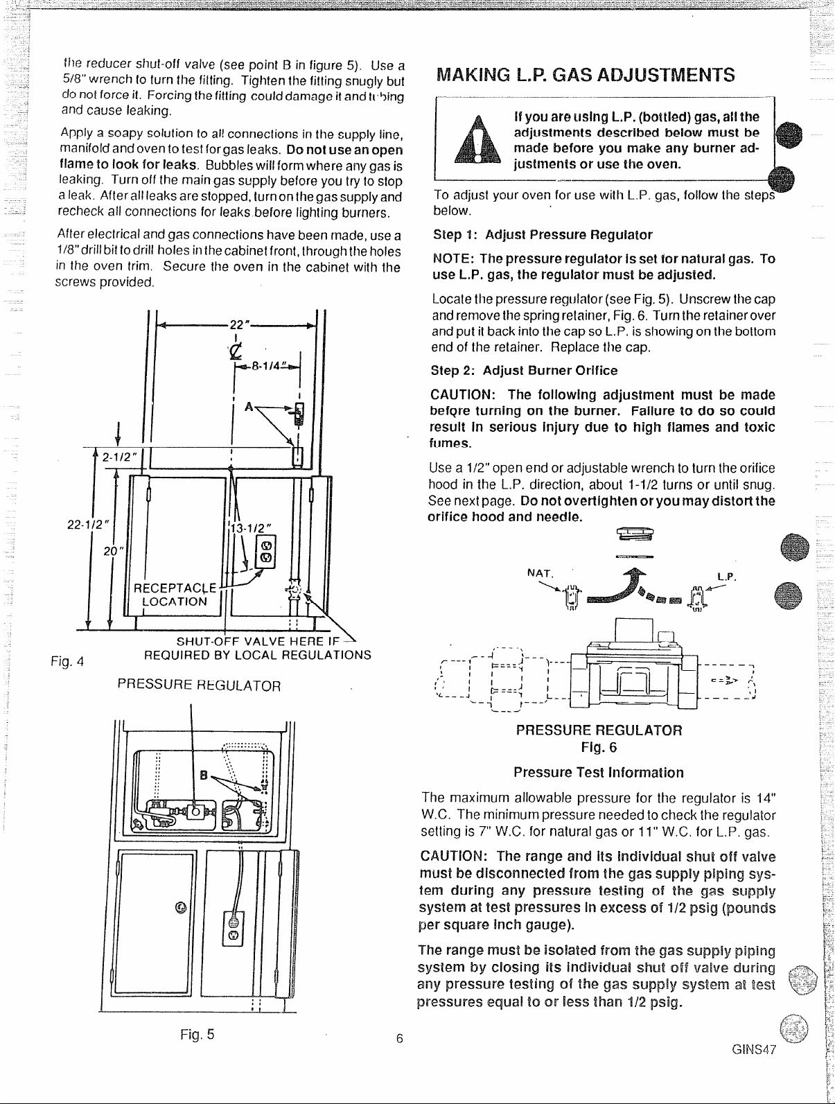
tl~ereducershut-off vaive[see point B in figure 5). Use a
‘
L-
.
;..
~~,
~-,
5/8”wrench10turnthe fit(ing. Tightenthefitting snuglybut
donotforceit, Forcingthefitting coulddamageitandti5ing
andcauseleaking,
Applya soapysolutionto ailconnectionsirrthe supplyline,
manifoldandoventotestforgas leaks. f30not useanopen
flame to look for leaks. Bubbleswill formwhereanygasis
leaking. Turnoff the maingassupplybeforeyoutrytostop
aleak. Afterallleaksarestopped,turnonthegassupplyand
recheckall connectionsfor leaksbeforelightingburners,
Afterelectricalandgas connectionshavebeenmade,usea
1/8”drillbittodrili holesinthecabinetfront,throughtheholes
in the oven trim. Secure ihe oven in the cabinet with the
screwsprovided.
IL----=---+-H
I GAS
r
below.
Step 1: Adjust PressureRegulator
hlOT~: Thepressure regulatorissetfornatura
use L.P. gas, the regulator must be adjusted.
Locatethe pressureregulator(seeFig.5). IJnscrewthecap
andremovethespringre!ainer,Fig.6. Turntheretainerover
andput ifbackintothecapsoL,P. isshowingon the bottom
endof the retainer. Replacethe cap.
Step2: Adjust Burner Orifice
CAUTION: The following adjustment must be made
bef~re turning on the burner. Failure to do so could
result in serious Injury due to high flames aild toxic
fu
gas. To
I
22-112“
Fig. 4
II
20
II
SHUT-OFFVALVEHEREIF>
REQUIREDBY LOCALREGULATIONS
PRESSURE REGULATOR
Usea 1/2”openend or adjustablewrenchto turntheorifice
hood in the L.P. direction, about 1-1/2 turns or urlil snug.
Seenextpage. Donot overtlghtenoryoumaydistortthe
orifice hoodand needle.
E=E!z?
—
1
I
I
:
I
J
=-
-1
-l’”-- “’L--
~.. ,{
:
----- =
\-
I —
I
I
,-–_t
PRESSUREREGLJLATOFt
~--- ,- -
1
:
1’‘
,/
% _ - -
I
Fig.6
Pressure Test Iilformatkm
The maximum allowable pressure for the regulator is 14” ‘
W.C. The minimumpressure needed tocheckthe regulator ~
....
setting is 7“W.C. for natural gas or 11” VV.C.for L.F’.gas. :
CAUTION: The range and its individual shut OffVahR ...
must be dkmnmcted from the gas supply piping systern during any pressure testing of the gas supply ~
system a! test pressures In excess of 1/2 psig (pounds $
per square inch gauge).
Fig. 5
—L
T
6
Page 7
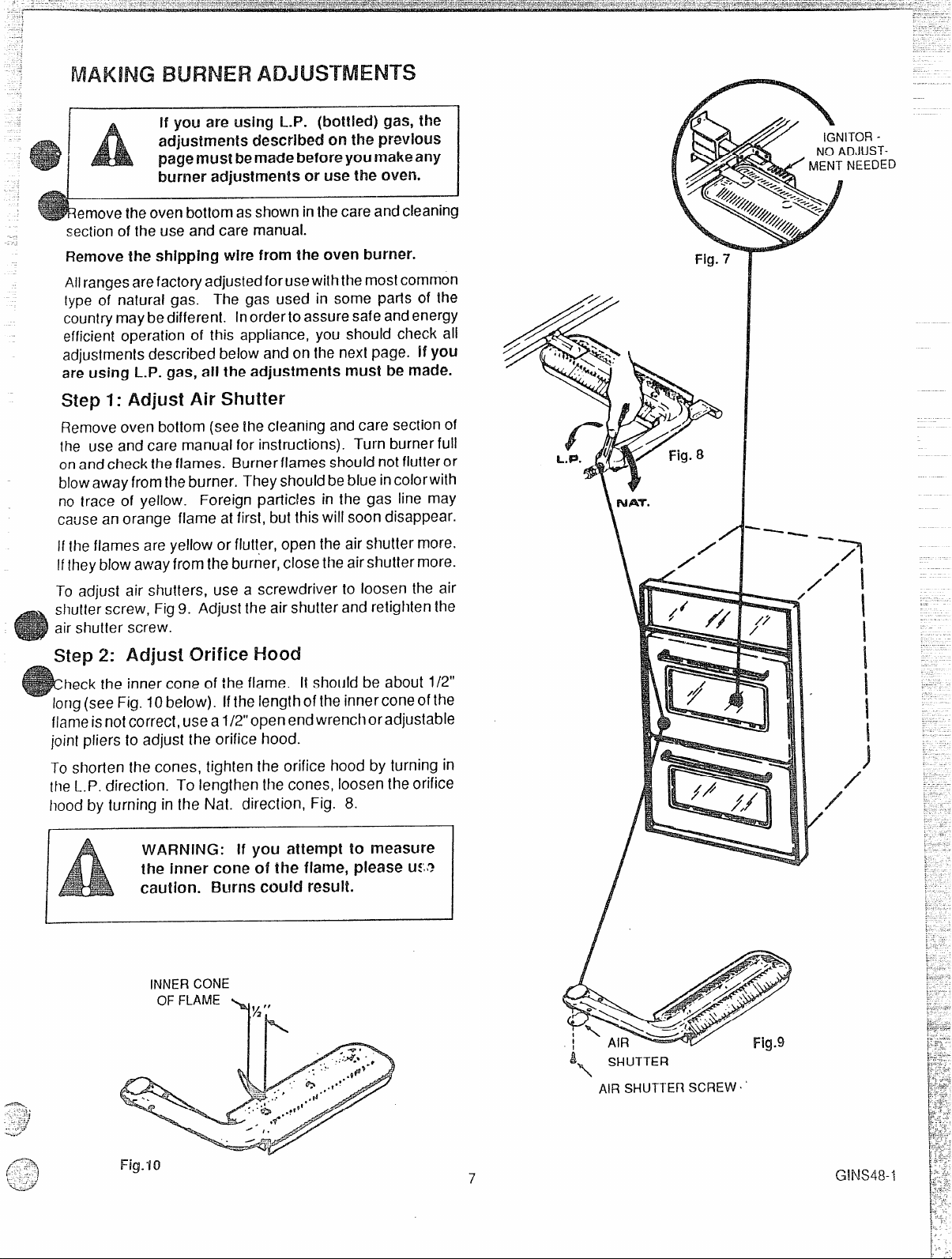
f
~..
, ,-
If you are usingi-.P. (bottied) gas, fhe
adjustmentsdescribedon the previous
pagemust bemade 13eforeyoumakeany
burner adjustmentsor usethe oven.
-J
ernoveIheovenbottomasshowninthecareandcleaning
secto thusancaman
Remoth
Ailrangesarefactoryadjustedforusewiththemostcommon
[ype of natural gas.
countrymaybedifferent. Inorderto assuresafeandenergy
efficient operation of this appliance, you should check ail
adjustmentsdescribedbelow and onthe nextpage. if you
areusing L.P. gas, aii the adjustments must be made.
step 1: Adjust Air shutter
Removeoven bottom (seeIhecleaning andcare sectionof
the use andcare manual
onandchecktheflames. Burnerflames shouidnot flutteror
blowawayfromtheburner. Theyshouldbeblueincolorwith
no trace of yellow.
causeanorange flame at first,but thiswill soondisappear.
Ifthe flames are yellow or flutter, open the air shuttermore.
If/hey blowawayfrom the burner,closetheairshuttermore.
To adjust air shutters, use a screwdriver to loosen the air
shutterscrew, Fig9. Adjust theair shutterand retightenthe
air shutter screw.
shipping wirefrom the oven burner.
The gas used in some parts of the
f instrucTurn burnerfull
Foreign particles in the gas line may
N
\
TOFIDJUSTNEEDED
Step 2: Adjust Orifice Hood
.
heckthe inner cone of the flame. It should be about 1/2”
long(see Fig. 10below). Ifthe Iengthofthe innerconeofthe
flameisnotcorrect,usea1/2”openendwrenchoradjustable
joint pliers to adjust the orifice hood.
To shorten the cones, tighten the orifice hood by turning in
theL.P. direction. To lengthen thecones, loosenthe orifice
hoodby turning in the fUa-t.direction, Fig. 8.
—
VWARNifW: if you attempt to measure
the inner cone of the flame, please u:’,,?
caution. Burns could result.
INNCO
O FLA~,
,72
SHUTTER
‘
AIRSHUTTEffSCREW~‘
GINS48-I
Page 8

.
Hu
Kethbof lau
B suyoovi insa gropr
erb a qualtech
ket ova cla f f
thithwibugasa otfla
vapors and liquids.
Always change oven rack positions
who i
co
Afbroialtat brp o o t
ova cli Leftoi t bro
c cao finetiy u t p
Always u d p holw remp
frt ovMoo d potc
castbu
Always usewhopeo doL h
a a sto bemofo
Always focleinsti t bo
Teach chin t plw o cono a
otpao t ov
F&t t r o replace any part of the ove
uninsa g i t b A o
w s b d b a s t
N h unf coP
b u m m cob a c
in
N l j o c o f o d n
t o N l g b
Y c k g f f
c u g a s a e o u
N u alf t l o b
Imu o f c s a f a c
inco
N b t f o coa v
t a tho v
N t t m a p o h f e a
d f f W u t f h c
N l cha o u w
a o i i u
N u Your oven f w o h a
u y o
starting i y
r S u c b d a c
dao p
N w ! f o h c w u y o
S c c c f
a c sei
N u a t o o b c a a p
hoS c c c f o a b
N s t i a o
Rea
undethinfoN
Shoy evneH y w n h t
f rea
Neu
sprethflam
The California Safe Drinking Water and Toxic Enforcement
Act requires the Governor of California to publish a list of
substances knownto the state to cause cancer and requires
businessesto warn customers of potential exposure tosuch
substances. Gas appliances can cause minor exposure to
three of these substances, namely benzene, formaldehyde
watc a grefirwion
D n - t m t p
1 c o d a t O
2 Hf cob s o W
f ‘ u a d chf ‘ t
extinguisher.
and soot, caused by the incomplete combustion of natural
gas or L.P. fuels. Properly adjusted ranges, indicated by a
bluish rather than a yellow
combustion. Exposure to these
mized further by venting with
ventilation fan or hood.
8
f w r i
s c b r
a o ! o using ~-
~~AF(;j~
+_J
Page 9

M
PC)FITANT:
num@ yoov
serial
nb fouo atabeh
eovendoor,ontheleftside
.-
I&the rangefront frame.
copy the numbers into the
spaceon
ual.
Themodeland
pa2 o this man-
I
0
-.-....-.-y.-.
y --~..... . .
!w
11 ~
-...................
. . . . . . . . . . ..... ... .... ..7. .
. . . . . . . . .
1
.-—
I)J–.
-T
1. Oven Light Switch
2.
Oven Control
3. Electronic Clock arm’Timer
4.
Oven Light
<
6. RemovableOvenRacksandGuides
~~-) 7. Removable Oven Bottom
,
‘-----
—
.“...,.,-.:.-,-,.+&,
~c.~“-.,
9
——
—-
.
8.
9. RemovableBroilPanGuides
10.
11.
12. Broiler
“..9
RemovableOvenDoor
Broil Pan and (3icf
RemovableBroilerDoor
GBm4
Page 10

“ S t Then
1. Turnthe Clock/Timerknobinlhe clockwkedirection unt
the words “SETTIMER” aredisplayed.
2. Turn the Clock/Timer knob in either direction to
amountoftirne. Thetimerwil!automaticallystartcountin
down.
Note: To cancel timer,turn the Clock/Timerknob untilthe
display reads:OO
Whilethe timer isbeingused,the time of daywill beshown
in the display about every 10 seconds.
Thetimer is a reminderonly andwill notcontrol theoven.
‘c-.—
3’
CLOCK
TIMER
T Set thClo
1. TurntheclocWtimerknobinthecOuntercloCkwisedirection
untilthe words “SET TIME”are displayed.
2. Turn the Clock/Timer knob in either directionto set the
time of day. Clock is now set.
TOBakeor Broil:
1. Set the OVEfVCONTFIOLto desired temperature or to
f3ROlL. Whenbroiling, besureto setthe knoballtheway
to the stop in the BROIL section of the knob. See the
following pages for more information.
2
Whenfinished, turn OVEN CONTROLto OFF.
O
CC)NTROL
OvenIgnition
When you turn the Oven Control on, the glow bar igniter
belowoven bottom beginsto heat. Whenthe igniter is hot
enough,inabout 1 minute,the gasflows into
is ignited.
The igniter glowsbright orangewhen hot. Itcycles on and
offwith the thermostat and will glow wheneverthe burner.
theburnerand
o
Duringapower faikwethe b c
b l and y Shtx.kfn t RI d w
Oven V
Whenthe ovenison, heatedairmovesthrough aventunder
the control panel. This hot air may make the control panel
area hot.
The vent is necessary for proper air circulation in the oven
and good baking results. Do not block this vent. Doing so
may cause cooking failure, fire or damage to Me oven.
Page 11

.....-.i
~.,,.:,<.,.,,.,
..,.,:.:.:,...,...:.....:.,,-
...............
. .....
,:...,:.......
.,,;:::~.
,...::,
,-....:..
.. .
L t o preheat thoroughly before
cooking 13akeclproducts. Allow 10-15 minutes preheat time.
Avoid opening the door too of-ten tO check
t f d b a h w b l
T m r i p b r
Cacom a q b
shb b i s p — t r
t h
golden c Y b a p c
shb
p
shh a
@Alwforecipe carefully.
@
Meaingrpro
6
U prop plac
(3
Pipao t ovraw 1M- 2 o
— b t s h a l
baked i g o d (
—t a t h —
brown, crisp crust.
b t
a spo a sio e p Av
overct ov
.
Pans too close to each other, to oven walls
or to the oven bottom
ment of air. Improper air movement causes
uneven browning and
block the free move-
coo
O tems b r 2
deb ret
i y u d p o o p g
T m b s o w t o i
f u T i c b t h o
n p a in
D n c t o b o a e
o r w f T f
mal
.
h f c c f a
dat o in
2 cake layers
4 CA%?layers
Q Moibaking shot. ddbe done on the second
shelf
posfrt botW ba
seviteu t sheplo t
seca foraposf t
boto t ovStap s t n
.
-4/
~ ,-
‘&.
p i CtilabanoB an
..
“ fo
t boto t ov
..
cakes on the first shelf posf
.
11
.
.
can block nor-
Page 12

s F3rushchickenandfishwithbutterseveraltimesas‘they
—
.————. .——————.-——
broil.Whenbroili~fish,greasethegititOpWve~$t~iW
andbroilwith
fish.
skinsidedown. Mis notneces~awto turn
Broiling is cooking by direct heat from the broii
burner.Tender cuts of meator marinated meat should
be selected for broiling. For best results steaks and
chops should be at Jeast%“thick.
After placing food on the broiler pan, put the pan on
the rack in the lower broiling compartment. The
recommended rack position and cooking time can be
found in the chart at right.
The closer the food is to the broil burner, the faster
the meat browns on the outside, yet stays red to pink
in the center. Moving the meat farther away from the
burner lets the meat cook to the center while browning outside. Side one should be cooked 1 -2 minutes
I
‘onger than side two. ‘
40LMOVWIC&XXand !XOMWdoor sim.dcif be cxm)!eteiyckm?dwhile broiling.
Jseonly the broiler pan and grid that came with your
ange for broiling. They are designed for proper drain[geof fat and liquids and help prevent spatter, smoke
wfire.
10not pwheat when broiling. Preheating may cause
!3
Ie thermostat to cycle the broil burner off and on.
tl-
F
w even broiling on both sides, start the food on a
C(
id pan.
T
‘im the outer layer of fat from steaks and chops. Slit
th
e fatty edges to keep the meat from curling.
w maximum juiciness, salt the first side just before
Fc
ming the meat. Salt the second side just before
tul
se
wing.
* hive a sdk! Lwdk pan h
in the pan may smoke or burn the next time the oven
is used.
@Be sure you $Wmw
w? mn’ed ‘for
the Grease
w agreaseflSeethe w on s
m n
l%xwdrdniaged hot M maywwe a !m3iler
m
If a f $ dose h? aw?lmma! kmwer
dcms am!
throw bakingsoda cm the
water on the fire.
After placing food on the broiler pan, slide the pan into
the proper rack position in the lower broiling compartment. Be sure the sump (greasewe!!) inthepanisto the
frontof the range.
Steak- 1“ Thick
Rare
Medium
Well Done 2 20-22
Ground Beef patties
Medium
Well Done
Lamb Chops - 1“ T
Pork Chops - 1“ Thick 2
Pork Shoulder Steaks
Ham We - 1“ Thick
Fish (Fillets)
Chicken (Halves)
Frankfurters
I
b
Bacon
Open-face Sandwiches 2
This chart is a genera! guide. The size, weight, thick-
ness, and starting temperature cd the fcmd as weli as
your own personal preference will affect Me mxking
time. Times in the chart are based on the food being at
refrigerator temperature.
4XWWt e broiler grid with k
t controls o MWe
Fhck
I
Food
F@Mon Total
3 =
1 =Lowest
2
*
1
2
2
f IDor p
-
1
I
20-25
I
4
I
10-15
I
5-7
6 :,, ..
I
I
I
I
I
I
&q:
::~’~=$
7-’5~-;.
b
i-.<,,.
; -;
<
.
Page 13

A
R
4i
3/4cup margarine,softened
1Cupsugar
2eggs
7cup sour cream
2 cups all-purposeflour
1teaspoonbakingpowder
1teaspoonsoda
1/teaspoonsalt
1teaspoonnutmeg
3/4cup light brown sugar
1/2cup choppedpecans
1teaspooncinnamon
Creammargarineandsugaruntil light andfluffy. Add eggsand sour cream;mix well. Combineflour, baking powder,soda,
saltand nutmeg.Add to batter and mix well. Pour batter into greasedand floured 13” x 9“ x 2“ baking pan.
Combine brown sugar, pecansand cinnamon; mix well. Sprinkle one half of this mixture over cake batter; swirl mixture
through batter.Sprinkle remainingone half mixture evenlyovercakebatter.
Coverand chill overnight. Uncover and bakein preheated 350°F oven for 35to 45 minutes or until cake tests done with
toothpick.
2-oz.pkg. frozen choppedbroccoli
1cup mayonnaise
1cup sharp cheddar cheese,grated
2 eggs,beaten slightly
1can creamof mushroom soup
...
..”,.... ... .
A delicious quick-to-make hearty stew that will feed a crowd or
another day,
1-10 oz. can barbecue beef
1-10 oz. can barbecuepork
7-24 oz.can Brunswick stew
1-5 oz. can boneless chicken
1-oz. can vacuumpacked corn niblets
1--16 oz.can baby lima beans,drained
2-16 oz.cans stewed tomatoes
1- 14’/2oz. can sliced okra, drained
...
...-.
..”.5. .
n
~-~~.#alno~{raand li~a beans. Add to all other ingredients in 4 ~uati
‘pan. I-leat.on medium to serving temperature,
●“‘..
B
,..
‘
..
2 tablespoonschopped onion
1cup cheesecrackercrumbs
Preheat oven to 375”F. Cook broccoli according to packagedirections; drain,
Mix with other ingredients. Pour into greasedtwo (2) quart casserole.Sprinkle
with cheesecracker crumbs. Bakeat 375°Ffor 20-25minutes.
feed the family. Refrigerate or freezethe remainder for
13
C -
Page 14

1/cumarga
;
i
,
;
{
.
f
:
.
!
~
p-
~
:.
k
[j
3/4 cuchopped greenpepper
CUp chOppedonion
113
3 eggs, well beaten
cacreamstyle corn
17oz.
1 ozcawhokernel corn with liquid
8’; oz.pkg.
1cuchedcheeshre
Preheatoven to 350°F.Sautdgreen peppersand onion in margarine; combine
with remaining ingredients except cheese.Pour into greasedtwo (2) quart casserole;sprinkle with cheeseand bake 45-55minutes in 350°F oven. Letstand 5
minutes beforeserving,
CourfeIllinCooperaExtenHomem
comuffin m
2-1 o sqsemch
1stmar
1c su
1 c fl
2 eggs
tsva
1
Dashsalt
1/2cup chopped pecans
Frozen 9“ pie shell
Preheat oven to 350°F. Melt chocolate and margarine, Add other
ingredients to melted mixture. Pour into unbaked pie shell an
bake 35-40 minutes or until pie appears set. Serve warm with ic
cream or whipped cream.
1-ozcan apple pie filling
12 cup sugar
1-9 oz. box white cake mix (1 layer size)
1stick margarine, melted
I 2 cup chopped pecans
Preheatoven to 350°F. Placein layers in greased 9“ or 10” square baking dish:
apples, sugar, dry cake mix. Pour melted margarine over top of cake mix. Bake
at 350°F for 35 minutes, Sprinkle with pecans. Continue baking 15 minutes.
approximately 2 tablespoons cookor 8“ or 9“ square baking pan. Place,fi- ‘:
Tilt pan to coat bottom evenly. Mix ~j>’
‘into hot greased pan. Bake 20-25
\ )1
‘=--
,,-.,-.\
‘:.;j;;j
L
.-
t.
t
:
Page 15

o t following page, t rer
r oven are shown. Refer t i w
r range.
VVarrrlwater, a mild detergent and a soft cloth are
!
PMn’-
e p o
n cle; ming
CLEAN!NGMATERIALS
s t u o a clp o y r A
purpose cleaners, s a Fac a b
u D n u m s p e
where recommended.
REMARKS
Controlpanel andknobs
Glassovendoor/window(some
models)
Ovenfinishes:
Continuous-cleaning (some
models)
Standard porcelain enameled
ovens, porcelain enameled
(smooth) areas of continuous-
ieaningovens,broi\ercompart-
P
ment,broiler pan
Oven Racks (and guides on
somemodels)
Detergent,warmwater,softcloth
Glasscleanerand papertowels
See specialinstructionson previouspage.
Detergent,warmwater,scouring Rinsethoroughlyaftercleaning.Whenusing
pador soap filledsteelwool pad
or non-aerosol (brush-on)oven
cieaner cleaningfinish. Ovencleanerswill damage
Detergent,
scouringpad or soapfilled steel
wool pad
warm water and
Donotuseabrasivecleaners.Knobspulloff
for easiercleaning.
Removestubbornsoilwith paste of baking
sodaandwater. Donotuseabrasivecleaners. Rinse thoroughly.
ovencleaneroncontinuous-cleaningovens
besureto keepitawayfrom thecontinuous-
the continuous-cleaningfinish. C)venbottom can be removed for easier cleaning.
Removeoven bottom of continuous-cleaningovens if cleaningit with ovencleaner.
Removefromoventoclean Drythoroughly.
Page 16

l-f
OVF
f3carefulrmt?,oscratchtheoven
or removingoven racks.
T“oInsta!i:
PLJ[thepegsontheendofIl]e rackguideinlothe holes
in Ihe oven back.
2.
Lockthe front hookinthe slot inthe oven side.
Set the raised back edgeof the ovenrackson a pair
3.
of rackguidessothehooksatthe sidesofthe rackrun
underneaththe rackguides.
4
Pushthe rack in untilyou reach the bump in the rack,
then liftthe frontof theracka bit andpushthe rackall
Iheway in.
To remove:
1.
Pullthe oven rackout, then up.
2. Lift thefrontoftherackguideto unhookitfromtheoven
wall and pull out.
OVEN AND BROILER
DOORS
Removethe doors for easier cleaning.
To remove:
1. Open the door fully andraise the releasetab on each
door hinge (see fig. A).
Raisethe releasetabsasfarastheywillgo(seefig. B),
2.
then close the door to the point where it will hold a
parlially open position.
3. Grasp thedoor firmly at IIIUsides,pul! IIIGloweredge
awayfrom theoven andlift thedooroff thehinge arms
(see fig. C).
To replace:
1. Slip thehingearms intothe upper portion of theslotsin
the door.
2. Lowerthe door to the fully open position and push the
release labs down (seefig. A).
Cl’(s A
finishwheninstalling
./’
/“
L
RACKHOOK
RELEASE >.
,.,.% ~ >$;
//
~ig. A ill
/-’
\
\
‘..
\
-..
..+’::b ‘~ “’,.,.$
~i9’ ~
Ill
I
‘.
!)
/
.. .,
.
/
RACK
BUMP
Fig. B
I
./
Fig. D
./”.<
OVEN
Removethe oven bottom for easier cleaning.
~e careful not to scratch the oven finish when removing or
installingoven bottom.
To remove:
1. Remove the oven racks and guides (see above).
2. Lilt the front of the oven bottom enough to clear the
front frame, fhen pull out.
TCIreplace:
1. Slidethe oven botlom into the oven so that Ihe back
edge of the oven bottom resls on the ridge inthe back
oven wall.
‘) Lowerlhe frontof theoven bol!om intoplace behind!he
k.
FRONT FRAME
16
Page 17

T LIGHT(
D notfmnchhot oven btDo no! touch bulb Wwi w
hands.Never wipe cwn lightarwith w doll?.
evtouthelectrlimecolo t bu
when replacing it.
edricd powermustbeshutoffifyouhaveb rep!acea
brokbul
Replth
bulb with a 40 watt, appliance bulb. J\n
appliance bulb is smaller than a standard 40watt house-
hobuani mat withhiovtem
turanhaa mulonbuli
-.
17
Page 18

Savetime and money—CWck this list beforeyou call for service.
-—-—,,....
TOeliminateunnecessaryserviced!s, first,readaiithe instructionsinthismanuai carefully. Then,ifyouhaveaproblem,always check this tist of common problemsand possible solutions bef~re you call for Se!ViCe.
PROBLEM
● C)venburnd n wo
POSSIBLECAUSE
o Gas supply notconnected or
~ Check the reducershut-offvalve andthe
not turned on. If using L.F’.
gas, tank may be empty
o Appliance not properly
* Check installation section inthis manual.
grounded or polarized. This
can affect spark ignition.
= Foodsdo not bake properly
o Controls notset correctly
w Burnersnotadjustedproperly
Oven not preheated long
o Check operating instructions in this
o Seethe installationsectioninthis manual.
o Be sureto preheat.
enough
Improper rack or pan place-
D Maintain uniform air space around pans
ment
Ovenventblockedorcovered
Improper use of foil
Impropertemperature setting
● Be sure oven vent is not blocked
o Foil use not recommended.
o Reduce temperature 25degrees forg!a ”-- ~
for utensil used
Recipe not followed
o Is recipe tested and reliable?
Improper thermostat calibra-
tion
Using improper cookware
DON’T CALLFOR SERVICE UNTIL
Y(XJCHECK
gas supply shut-offvalve tobe surethey
areopen (see installationsection)
Ifusing L.P. gas; is there any gas in the
L.P.tank?
manual.
10 minutesbelow 350 degrees
15 minutesabove 350 degrees
and utensils; see oven cookingsection.
or dull/darkened pans.
d
A
$l!ll
Page 19

..
-Y
I
Foodsdo not broil
I
~ Oven smokes. c Dirtyoven
e !rnproperrack position
o Ovenpreheated
o Improperutensil used
o Improperbroilingtime
I
● Broilerpan full of grease left in
oven
s Check in broiling section.
o
D not preheatwhen broiling.
U broiler pan and grid supplied with
*
range.
o Checkbroiling chart in broilingsection.
o Checkfor heavyspillover.
o Cleanpan and grid after eachuse.
~ 13esure that sump (grease well) isto thefron
of the rangewhen broiling.
..
Lightswitch inoff position
D Ovenlight orwork light
does notwork (if
equipped).
= Continuous-Cleaning ~ Heavyspilioverswere not wipec
ovenfinish looks soiled up
(continuous-clean
modelsonly)
mperature in your newovenhas been set correctly at
thefactory,sobe sureto followthe recipetemperaturesand
times the first few times you bake in your newoven.
If you think the oven should be hotter or cooler, you can
adjust it yourself. To decide how muchto change the temperature,set the oventemp knob25°F higheror lowerthan
the temperature inyourrecipe,thenbake. Theresultsof this
‘lest” should give you an ideaof howmuchthetemperature
shouldbe changed.
o
c Lightbulb burnedout
I
l-cl ikrmkx
“ Checkswitch setting.
o Checkor replacelight bulb; see cleaning
and care instructions.
“ See continuous-cleaning oven information in
cleaning andcare sec!ion.
The continuous-cleaningovenfinish will not
keep your oven spotless, only presentably
clean.
4.
Holdthe knob handle (Aon illustration)while turningthe
knob skirt (B on illustration) in the desired direction. As
you turn, you should be able to hear clicks and feel
notchesorteeth. Eachclickor notch is 100. Youcanturn
upto 5 clicks or notches in either direction.
When you reachthe desired adjustment, retighten both
5.
screws.
B
D
B
P
I. Turn OVEN CONknt OFF and remove the
knob by pulling straight off.
.2.Lookat the back of the knob.The arrow pointing to the
center of the upper screw indicates the original factory
setting.T knob can be adjusted up to 5 Fhoo
5 cooi 1 incr
?. U a screwdriverto loosen thetwo screws about 1turn
each.
MACMCX30LER
(S
MovedToCh
19
MAKES
@crewMOW*TowardI-lo!tw)
O
Gsrml 8
Page 20

IfYbLJNeed Service
To obtain service, seeyour warranty
on the back pageof thisbook.
We’re proud of our serviceand want
youto be pleased. If for some reason
youare not happywiththeserviceyou
receive,herearethree stepsto follow
forfurther help.
FIRST, contactthe peoplewho servicedyour appliance. Explainwhyyou
are not pleased. In mostcases, this
will solvethe problem.
NEifyouarestill notpleased,write
all the details-including your phone
number-to:
Manager, Consumer Relations
RCA
Appliance Park
Louisville, Kentucky40225
FINALLY, if your problem is still not
resolved,write:
Major Appliance
Consumer Action Panel
20 North Wacker Drive
Chicago, Illinois 60606
.
Page 21

R
le
Save proofof originaipurchasedate suchas your salessliporcancelledcheckto establishwarrantyperiod.
—— —
FULLONE-YEARVVAFIF3ANTY
Foroneyearfrom the date of
originalpurchase,we willprovide,
free of charge,partsandservice
laborin your hometo repairor
repiaceanypiwf of the oven that
fails becauseof a manufacturing
defect.
Thiswarranty is extendedto the
originalpurchaserandanysucceedingownerfor productspurchasedfor
ordinaryhomeuse inthe 48 mainland states, HawaiiandWashington,
D.C. InAlaskathe warrantyisthe
same exceptthat it is LIMITED
becauseyou must payto ship the
productto the serviceshop or for the
servicetechnician’stravel costs to
your home.
INHAT I N Cx
● Servicetrips to yourhometo teach
you howto usethe product.
F?eadyour We and Care material.
If you then haveany questions o Failure of the product if it is
operatingthe product,
ab
please contact your dealer or
Consumer Affairs officeat address
below.
o Improperinstallation.
If you havean installationproblem, SIBLE FOR CONSEQUENTIAL
contact your dealer or installer. You
are responsiblefor providing ade-
quate electrical, plumbing and other
connecting facilities.
.
We at
est quality productsandservice.
Therefore,we havedesignated(3E
COS a leaderin
the serviceindustry,to fulfill your
serviceneeds. Shouldyourappliance
needservice,duringthe warranty
periodor beyond,look inthe Whiteor
Yellow pagesof yourtelephone
directoryfor GE CONSUMERSERVICEor an AUTHORIZEDRCAAPPLlANCE SERVICER.
o Replacementof housefuses or
resettingof circuitbreakers.
for other than its intendedpurposeor
o
used commercially.
E Damageto product caused by
accident,fire, floods or acts of God.
WARRANTOR IS NOT 13ESPON-
DAMAGES.
———
——
R striveto providethe high-
[
—.
u
(
Sostates do notallowtheexclusionorlimitationofincidentalorconsequentialdamages,sothe Aove
limitationor exclusionmaynotapply
othrigwhvafrstt stT k w y
conyoloo stconaffofo y stAtGe
Hfurther help is needed concerning this warranty, write:
t yoThwargiy spl ria y m a h
ria i y s
Warrantor: FKL4Appliances
Manager—Consumer Affairs, FICA,
Appliance Park, Louisville, KY 40225
 Loading...