

Page 1
Installation
JXBC67 Kit
Instructions
WARNING
TO REDUCE THE RISK OF FIRE,
ELECTRIC SHOCK OR INJURY TO PERSONS, OBSERVE THE FOLLOWING:
A. Use this unit only in the manner intended by the
manufacturer. If you have questions, contact the
manufacturer at the address or telephone number
listed in the warranty.
B. Before servicing or cleaning unit, unplug or switch
power off at service panel and lock service
disconnecting means to prevent power from being
switched on accidentally. When the service
disconnecting means cannot be locked, securely
fasten a prominent warning device, such as a tag, to
the service panel.
C. Installation work and electrical wiring must be done
by qualified person(s) in accordance with all
applicable codes and standards, including fire rated
construction.
D. Sufficient air is needed for proper combustion and
exhausting of gasses through the flue (chimney) of
fuel burning equipment to prevent back drafting.
Follow the heating equipment manufacturer’s
guideline and safety standards such as those
published by the National Fire Protection
Association (NFPA), and the American Society for
Heating, Refrigeration and Air Conditioning
Engineers (ASHRAE), and the local code authorities.
E. When cutting or drilling into a wall, ceiling or floor,
do not damage electrical wiring and other hidden
utilities.
F. Ducted fans must always be vented to the outside.
• For general ventilating use only. Do not use to
exhaust hazardous or explosive materials and
vapors.
For Outdoor Remote Blower Locations
AVERTISSEMENT
IL FAUT OBSERVER LES
PRÉCAUTIONS SUIVANTES POUR
RÉDUIRE LES RISQUES D’INCENDIE, DE
CHOC ÉLECTRIQUE OU DE BLESSURES.
A. Utiliser cet appareil uniquement de la manière
prévue par le constructeur. Pour toute question
concernant cet appareil, contacter le constructeur
à l’adresse ou au numéro de téléphone indiqué
dans la garantie.
B. Avant une intervention ou le nettoyage de l’appareil,
le débrancher ou couper l’alimentation électrique au
panneau électrique et verrouiller le coupe-circuit
pour empêcher la remise accidentelle sous tension.
Quand il n’est pas possible de verrouiller le coupecircuit, mettre fermement en place un dispositif
d’avertissement, une pancarte par exemple, sur le
panneau électrique.
C. Les travaux d’installation et de câblage électrique
doivent être faits par des personnes qualifiées,
conformément aux codes et réglementations, y
compris une construction résistant aux incendies.
D. Il doit y avoir suffisamment d’air pour permettre la
combustion et l’évacuation des gaz dans la
cheminée de tout équipement à foyer, afin d’éviter
un retour de flamme. Il faut suivre les directives du
constructeur de l’équipement de chauffage et les
normes de sécurité telles que celles publiées par le
Code national de prévention des incendies du
Canada et l’American Society for Heating,
Refrigeration and Air Conditioning Engineers
(ASHRAE) et les codes locaux.
E. Lors de la coupe ou du perçage dans un mur, un
plafond ou un sol, il faut prendre soin de ne pas
endommager les fils électriques et autres services
cachés.
CAUTION: Before beginning
installation, read the Installation Instructions provided
with the Downdraft Vent. Insure that the duct run does
not exceed maximum permissible length for the
cooking product being installed.
F
. Les ventilateurs canalisés doivent toujours être
évacués à l’extérieur.
• Pour utilisation pour la ventilation générale
seulement. Ne pas utiliser pour évacuer des
matériaux ou des gaz dangereux ou explosifs.
PRUDENCE – Avant de com-
mencer l’installation, il faut lire les instructions fournies
avec l’évent vertical vers le bas. Vérifier que la longueur
du conduit n’est pas supérieure à la longueur maximale
permise pour l’appareil de cuisson à installer.
1
Page 2
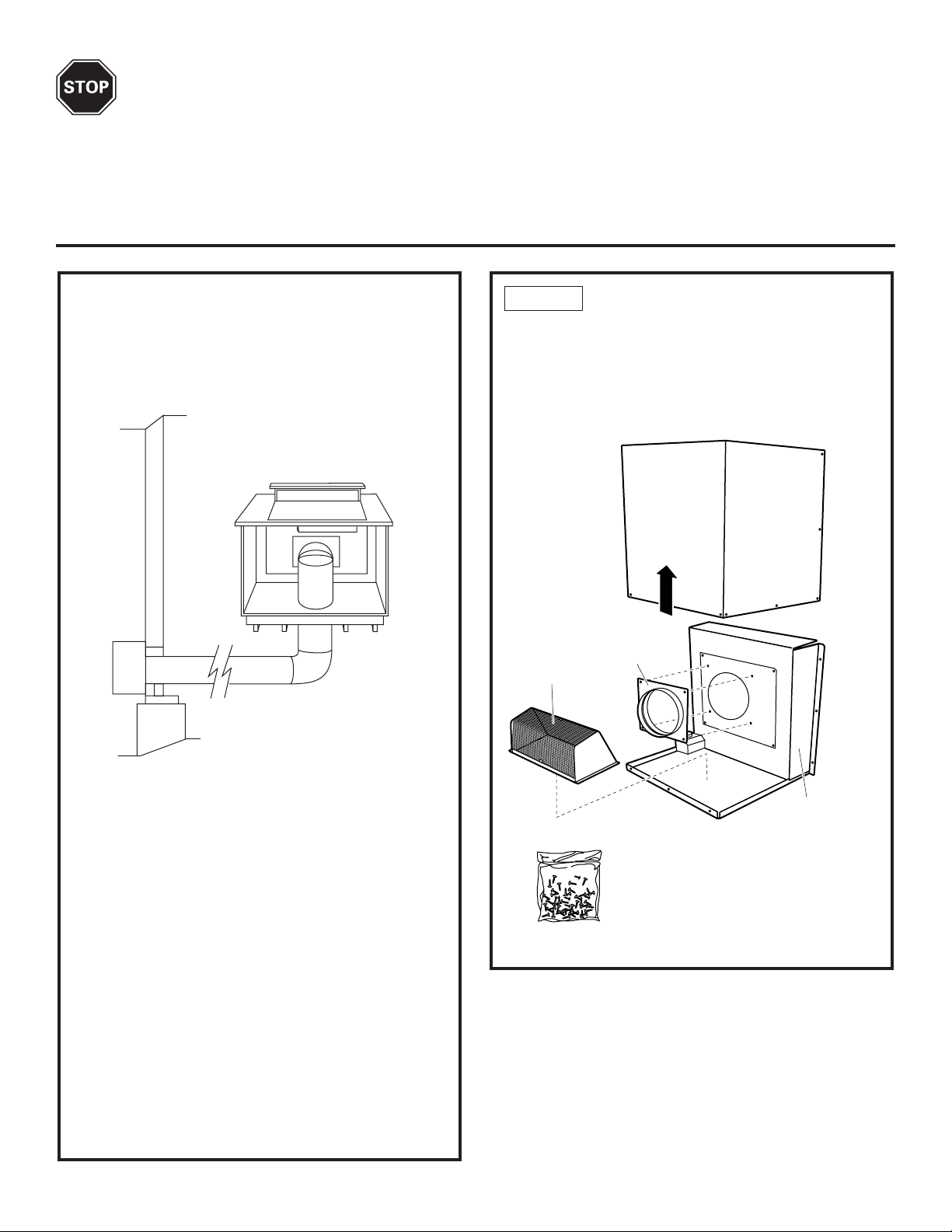
BEFORE YOU BEGIN
Adapter
Plate
Base Assembly
Damper
Read these instructions completely and carefully.
IMPORTANT - Save these instructions for local inspector’s use.
IMPORTANT - Observe All Governing Codes and Ordinances.
Note to Installer - Be sure to leave these instructions with the Consumer.
Note to Consumer - Keep these instructions for future reference.
JXBC67 KIT
The blower and motor assembly can be mounted on
an outside wall. This kit provides a means to mount
the blower outdoors with a protective cover. It should
be installed in an accessible and unobstructed
location, at least 10" above the ground.
STEP 1 CHECK PARTS SUPPLIED
• Separate the cover from the base assembly by
removing 5 screws. Lift off the cover. Retain all
screws.
• Remove the damper and the adapter plate. Be
careful not to damage the damper.
Materials Required (not supplied)
• Approved liquid tight service connections for use
between the wire compartment on the base and
inside the structure.
• 7 wire nuts or other approved connectors.
• (6) 5/16” dia. fasteners compatible with the type of
material the base is being fastened to.
• 6” round duct, sufficient length to reach the outdoor
installation location.
• Two 6" round 90° elbows
• 6" round duct, length to reach blower location
• Electrical cable and connectors, sufficient length to
connect the downdraft vent to the remote blower
location. 14-guage min. is recommended, must
conform to local codes.
Tools required:
• Chalk or Pencil
• Measuring tape
• Drill with appropriate bits
• 1/4", 3/8" and
7/16" Nut driver
• Duct Tape
• Safety glasses
Package of screws
2
Page 3
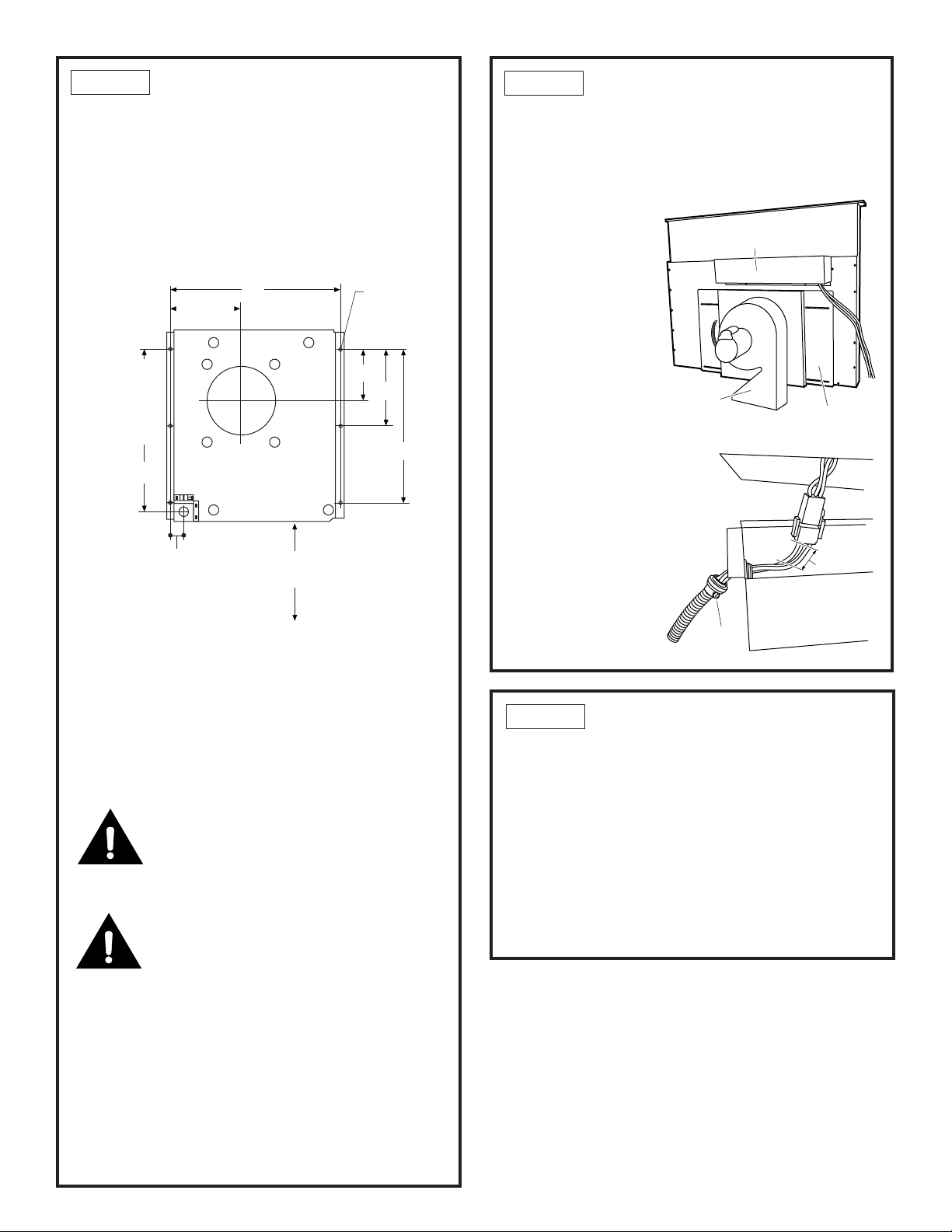
STEP 2 MARK MOUNTING
LOCATION
• The base is designed to be mounted to studs 16” on
center or to other suitable exterior surfaces. Use the
dimensions shown to determine the location of the
ducting and wiring through the wall.
OR
• Place the base against the exterior wall and mark
the 6 mounting locations, the 6” duct location and
the hole for the wiring. Use pencil or chalk.
16"
6-11/16"
Align
With Duct
Opening
On Outside
Wall
6-1/8" Dia.
12-15/16"
6 Holes
For 5/16"
Fastners
5-1/8"
6"
12"
STEP 3 PREPARE THE VENT
• Flatten the shipping box to use as a pad.
• Place the unit on its back and onto the protective
pad.
• Remove the 3 screws holding the control box on the
plenum. Retain screws.
• Cut the blower
leads approximately 3” from the
plug on the end of
the vent.
• Remove the blower
conduit by loosening the screw on
the fitting.
Blower/
Motor
Control Box
Mounting
Plate
1-13/16"
• The bottom of the base assembly must be 10” Min.
above the ground. There should be no obstructions
to the discharge from the damper.
• Cut a 6-1/8” Dia. hole in the vertical structure to
accommodate a 6” round duct. Cut another hole for
the wiring.
• Drill 6 pilot holes through the wall for the 5/16”
fasteners (not supplied). Use fasteners appropriate
for the type of construction.
10" Min
Above Ground
CAUTION
When cutting or drilling into a wall or ceiling, do not
damage electrical wiring or hidden utilities.
PRUDENCE
Lors de la coupe ou du perçage dans un mur ou un
plafond, il faut prendre soin de ne pas endommager
les fils électriques et autres services cachés.
• Check for interference with floor joists and stud
walls. If necessary, locate the base to provide a
secure installation.
• Place a 6” round duct through the hole extending
approximately 3” from the wall to provide a proper
seal with the blower. Secure the duct to the building
structure to prevent it from being pushed back when
the blower is installed.
3"
Control Box
Loosen
Screw
STEP 4 REMOVE THE BLOWER
• Remove the 4 screws holding the blower to the
mounting plate. Retain all screws.
• Lift the blower off the assembly, turn it over to
access the 4 nuts holding the blower to the mounting
plate. Remove the nuts, lift the mounting plate off the
blower.
• Reinstall the mounting plate onto the plenum with
the 4 original screws.
IMPORTANT: Do not lift motor by power cable.
Damage will occur!
3
Page 4

STEP 5 INSTALL ADAPTER PLATE
STEP 7 CONNECT DUCTWORK
• Install the adapter
plate over the
mounting plate on
the plenum with the
flange towards the
outside. Use 4
screws provided.
Install Adapter
Plate
• Install the vent into the cabinet according to the
installation instructions packed with the vent.
STEP 6 CUT DUCTWORK HOLES
• Install a section of 6" round duct through the cabinet
floor.
• Connect the plenum to the ductwork with 90° elbow.
Secure the joint with sheet metal screws. Tape to
seal all joints.
• Install 6" round duct to reach the outdoor motor
assembly.
Duct Tape
Over Seam and Screw
Air
Flow
Screw
• DO NOT USE flexible plastic ducting.
• Use the straightest duct run possible.
• For satisfactory performance the duct run should not
exceed 150 ft. Refer to the table of equivalent lengths.
• Install ductwork so the piece of duct nearest the
downdraft unit slots INTO the next piece of the duct.
Secure the joints with self-tapping screws and apply
duct tape around the joints to ensure an airtight seal.
90°
Elbow
Cut a
6-1/2" Dia.
Hole
• Place the 90° elbow over the adapter plate.
• Mark the location for a 6-1/2" round hole in the floor
of the cabinet.
NOTE: Check to be sure there is no interference
below the cabinet floor. The mounting plate on the
plenum can be shifted 3-1/2" to the left or right sides.
• Cut the hole through the cabinet and another hole
through the floor below.
Check for
Interference
Below Floor
STEP 8 CONNECT VENT WIRES
• Use electrical cable and connectors that conform to
local codes (14 gauge min. is recommended). Use a
length to reach between the vent and the blower/
motor location.
• Attach the wire box removed from the blower
conduit to the end of new wiring.
Control Box
Tighten
Screw
• Use wire nuts to secure the wire to the 3” remaining
wires with plug.
• Reinstall wire box with original screws.
4
Page 5

STEP 9 MOUNT BLOWER
• Mount the blower onto the base assembly. The studs
on the motor will mate with holes on the assembly.
Secure with 4 nuts from the hardware bag.
STEP 10 CONNECT BLOWER
WIRES
• Check that the red plastic anti-short bushing is
secured in the end of the conduit. Install the blower
conduit into the conduit connector on the junction
box and tighten the screw.
• Run the electrical wiring from the downdraft vent to
the wire compartment. Install a liquid tight service
connection where the wire enters the compartment.
The fitting should be sized to fit wire being used.
Blower
Conduit
STEP 11 FINALIZE INSTALLATION
Install
Damper
• Place the cover over the assembled kit and secure
with 16 screws.
• Install damper to outlet on the bottom with 4 sheet
metal screws. Reach inside the damper to be sure it
moves freely.
TEST OPERATION
• Turn power on at the circuit breaker. Plug power
cord into a properly grounded receptacle.
• Refer to the Downdraft Vent Owner’s Manual for
operating instructions.
Red Anti-
Base
Assembly
Wire From
Vent
Install
Liquid Tight
Connection
• Attach the green ground leads from the wire
compartment, connecting one to the green ground
lead on the blower and the other to the ground lead
of the wiring from the downdraft vent.
• Connect the neutral (white) and power lead (black)
from the blower to the leads from the downdraft
vent.
• Use wire nuts to connect wires.
Green Ground
Short Bushing
Conduit
Connector
Wire
Compartment
Leads
5
Page 6

Notes
6
Page 7

Notes
7
Page 8

959-0295-001 SPECIFICATIONS SUBJECT TO CHANGE WITHOUT NOTICE Pub. No. 49-80186
8
Dwg. No. 164D4290P342
(N.D. 682) 2/03
 Loading...