

Page 1
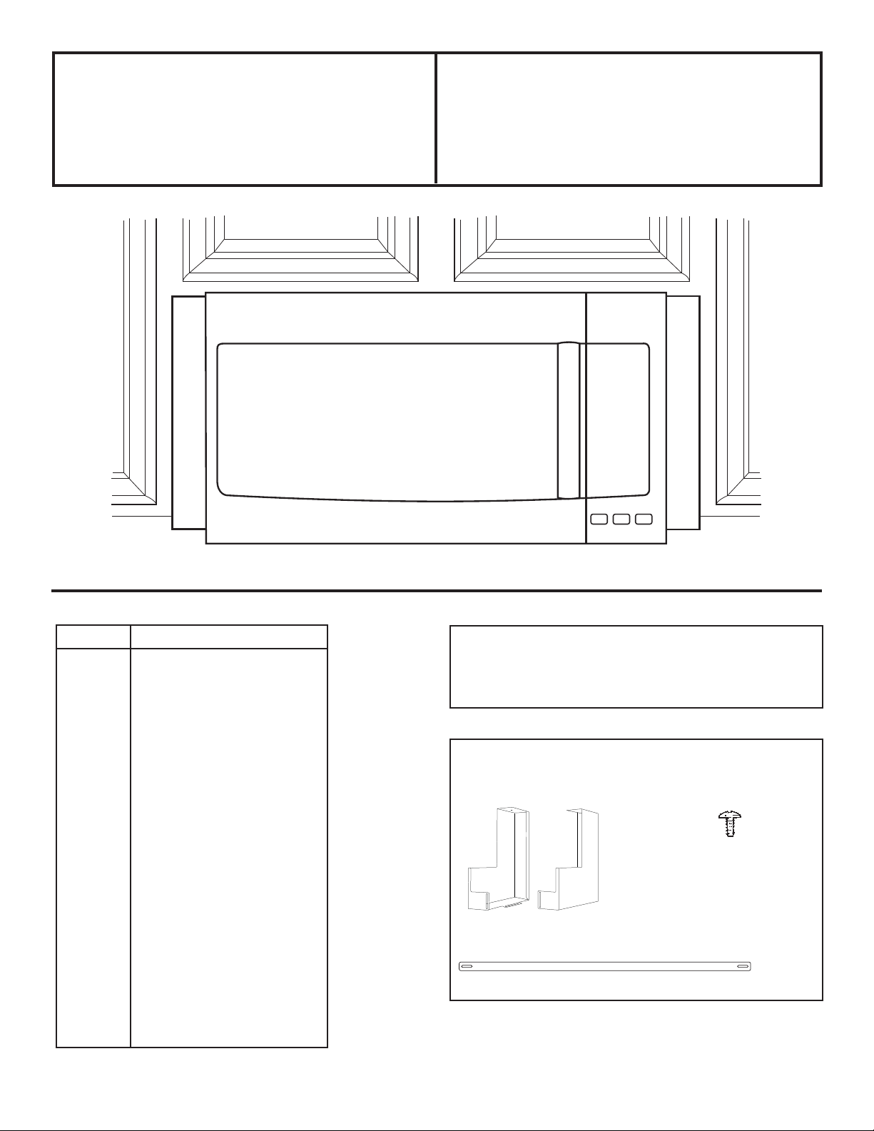
Installation Filler Panel Kit
Instructions
JX36
FOR 36” INSTALLATIONS
Kit Model
JX36B CVM519
CVM721
CVM1750
CVM1790
CSA1201
CVM517
CVM521
JVM3160
JVM3162
JNM3163
JVM6172
JVM6175
DVM7195
JVM7195
JNM7196
PSA9120
PSA9240
PVM9005
PVM9179
PVM9215
PNM9216
QVM7167
RVM5160
TOOLS YOU WILL NEED
• Phillips screwdriver
PARTS INCLUDED
• Trim kit side mount (2)
• Connecting Bar (1)
• Installation screws (2)
31-7000104 Rev. 1 11-20 GEA
Page 2
Installation Instructions
Install the OTR bracket according to OTR
Installation Instructions.
NOTE: This kit is best installed with 12” base
cabinets. Cabinets with greater than a 12” base
may have a larger gap between back wall and
kit.
NOTE: Ensure the OTR and the Cooking
Product installation manuals are followed.
OTR Bracket
KIT INSTALLATION
1. Place the microwave on a flat surface where
you can work on the bottom of both sides.
2. Remove all 3 pieces from the package (right
panel, left panel, top brace.
3. Remove the screws from the lower back
corner of the microwave.
4. Your microwave will have 1-3 screws on the
bottom left side. Remove these screws to
create a gap between the bottom plate and
the case of the microwave.
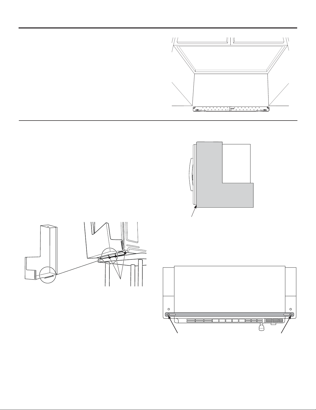
7. Make adjustments so the side panel is in line
with the front of the microwave case.
Flush with front of
microwave case.
8. Repeat the same procedure for the other side.
9. Using the 2 flat head screws provided, attach
the top brace to the 2 side panels to pull both
panels together.
Screw
Holes
5. With the short edge of the side trim to the
back of the left side of the microwave, slide
the lower lip of the side panel inside the gap
between the bottom plate and the case.
6. Attach the side trim to the back of the
microwave using the screw removed in step 3,
then reattach the screws removed in step 4 to
the underside of the microwave.
Printed in the USA
Must use two forward holes for the top brace
10. Install the over-the-range microwave with side
panels into the 36” opening.
NOTE: Make sure you have installed the
mounting wall bracket in the center of the 36”
opening per the installation instructions provided
with your microwave.
2
 Loading...