

GE JX2130 Installation Instructions Manual
Installation
Instructions
Built-In TrimKits
JX2127andJX2130
Questions?Call GEAnswer Centerat 800.626.2000or Visito,u-X_bsite,t: www.GEAppliances.com ]
BEFORE YOU BEGIN
Read these instructions completely and carefully.
• IMPORTANT - S.,ethese
inst_ uctions fin" local inspector's use.
• IMPORTANT - Obse,.e.U
governing codes and ordinances.
• Note to Installer - Be sure to leave these
instructions with the Consumer.
° Note to Consumer - KeeI)these instructions
tot fllttu'e reference.
• For easier installation and personal safety, we
recommend that two people install this microwave oven.
• Unplug the microwave oven beflwe attempting
installation of this kit.
FOR YOUR SAFETY:
WARNING - Bef.,ebeginning the
installation, switch power off at service panel and lock
the service disconnecting means to prevent power
from being switched on accidentally. When the service
disconnecting means cannot be locked, securely tasten
a prominent warning device, such as a tag, to the
service panel.
TOOLS YOU WILL NEED
#2Phillipsscrewdriver
Pencil
Awl or punch
Drill with 7A/'bit or#35
Scissors(optional) Tapemeasure
READ CAREFULLY.
KEEP THESE INSTRUCTIONS.
Skill level - Installation of this appliance requires basic
mechanical and electrical skills.
° Completion time - 1-3 horn's
• Proper installation is the responsibility of the installer,
• Product failure due to improper installation is not
covered trader the _4"u'rantv.
This kit is UI, listed for installation ahme or over
any (;eneral Electric/Hotpoint/RCA single electric
wall o_,eil.
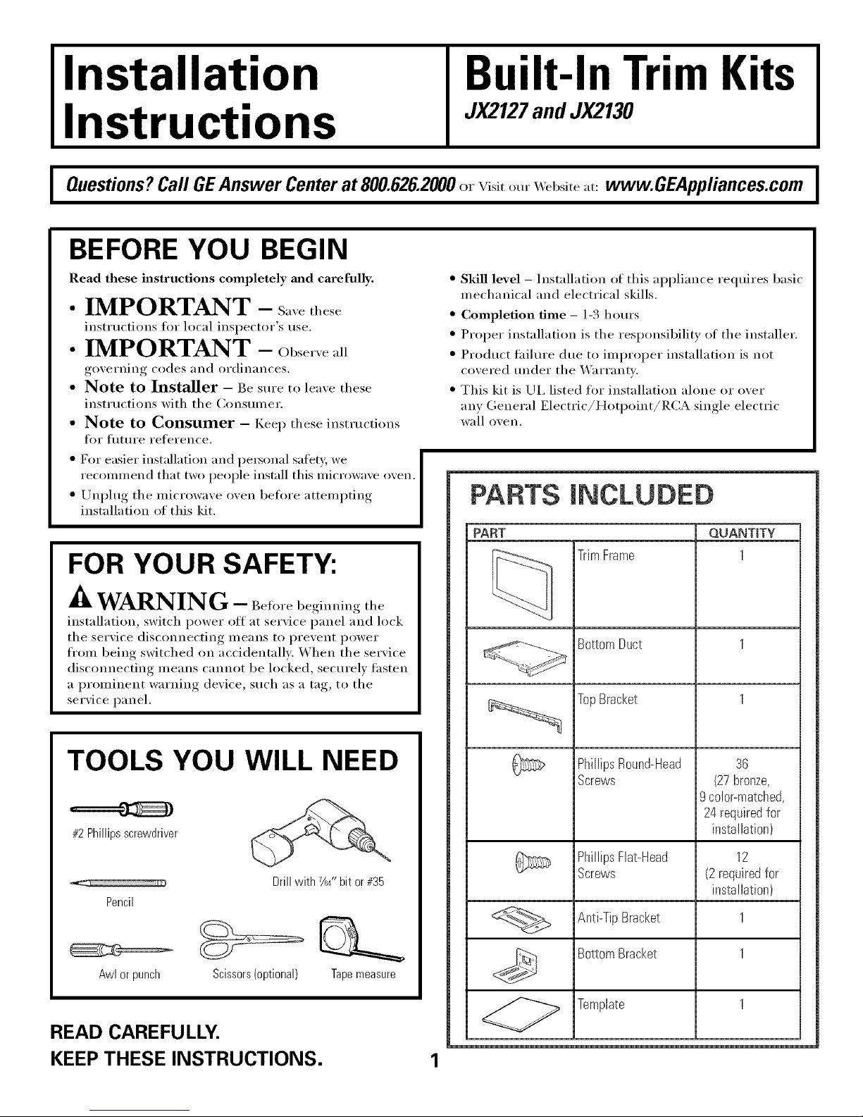
PARTS iNCLUDED
PART OUANTtTY
TrimFrame 1
BottomDuct 1
TopBracket 1
PhillipsRound-Head
Screws
36
(27bronze,
9 color-matched,
24 requiredfor
installation)
PhillipsFlat-Head 12
Screws (2 requiredfor
installation)
Anti-TipBracket 1
BottomBracket 1
Template 1
Installation Instructions
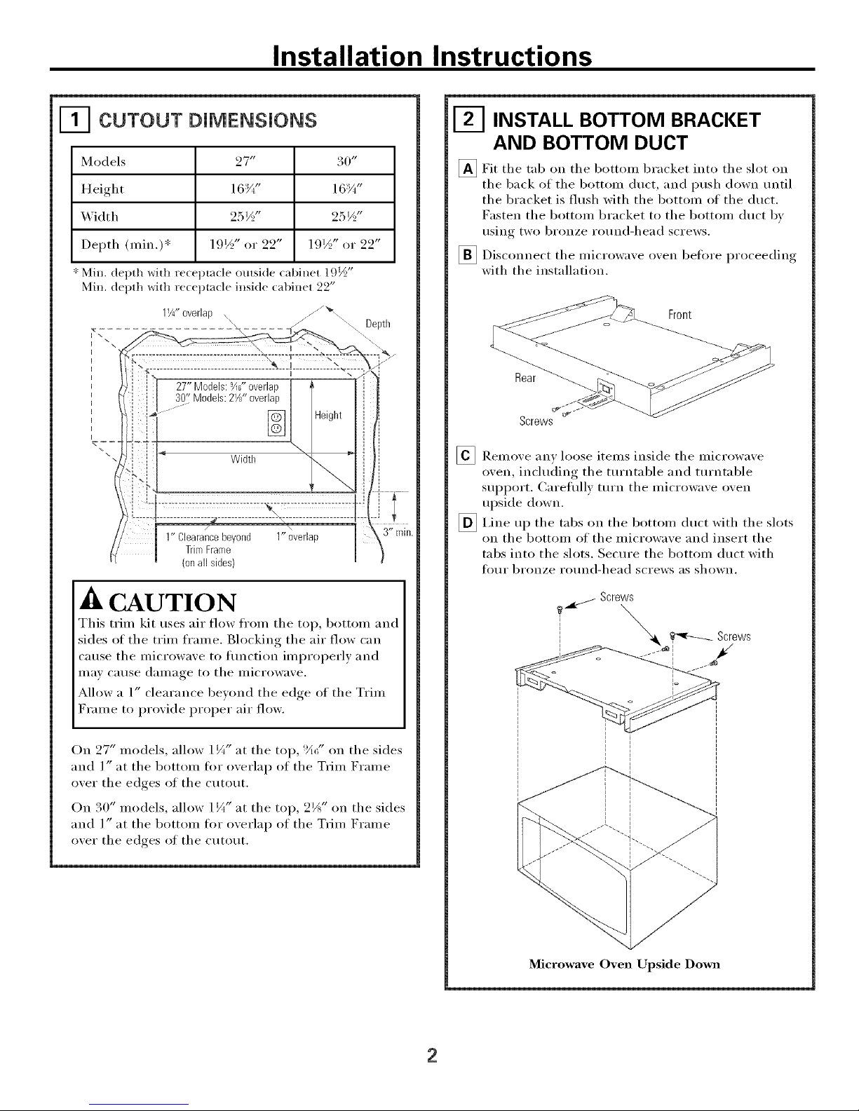
CUTOUT DiMENSiONS
Models
Height
Width
Depth (nfin.)*
* Min. depth with rece
Min. depth with rece
27 tr
16%"
25½"
19½" or 22"
1.½
)ta(le Olltside (;tbii/et QI 9"
m_(le inside _abinet 22"
1%"overlap ...........
30"
16:_"
25½"
19½" or 22"
Depth
1" Clearancebeyond 1"overlap
TrimFrame
(onall sides)
A CAUTION
This trim kit uses air flow fl'om tile top, bottom and
sides of tile trim frame. Blocking tile air flow can
cause tile microwave to flmction improperly and
Ill,IV C_ltlSe dalllage to tile illicYowave.
Allow a 1" clearance beyond tile edge of tile Trim
Frame to provide proper air flow.
On 27" models, allow 1 i/_,, at tile top, !_;" on tile sides
and l" at tile bottom for oxerlap of tile Trim Frame
oxer tile edges of tile cutout.
l zt
On 30" models, allow l ¼ at tile top, 2JA" on tile sides
and l" at tile bottom for oxerlap of tile Trim Frame
oxer tile edces of tile cutout.
INSTALL BOTTOM BRACKET
AND BOTTOM DUCT
_Fit tile tab tile bottom bracket tile slot
into
(111 oil
tile back of tile 1)ottom duct, and push down until
tile bracket is flush with tile bottom of tile duct.
Fasten tile bottom bracket to tile bottom duct b_
rising two bronze ro/ind-head screws.
_ Disconnect tile microwa',e o',en 1)elore _roceeding
I ,
with tile installation.
Front
Rear
Screws
_ Remove any loose items inside tile microwave
oven, including tile tm'ntable and turntable
support. Careflfllv tm'n tile microwave oven
upside down.
_ I,ine tile tabs tile bottom duct with tile slots
lip
Oil
on tile bottom of tile microwave and insert tile
tabs into tile slots. Secm'e the bottom duct with
four bronze ro/md-head screws as shown.
f Screws
I % _ Screws
, i
Microwave Oven Upside Down
2
 Loading...