

Page 1
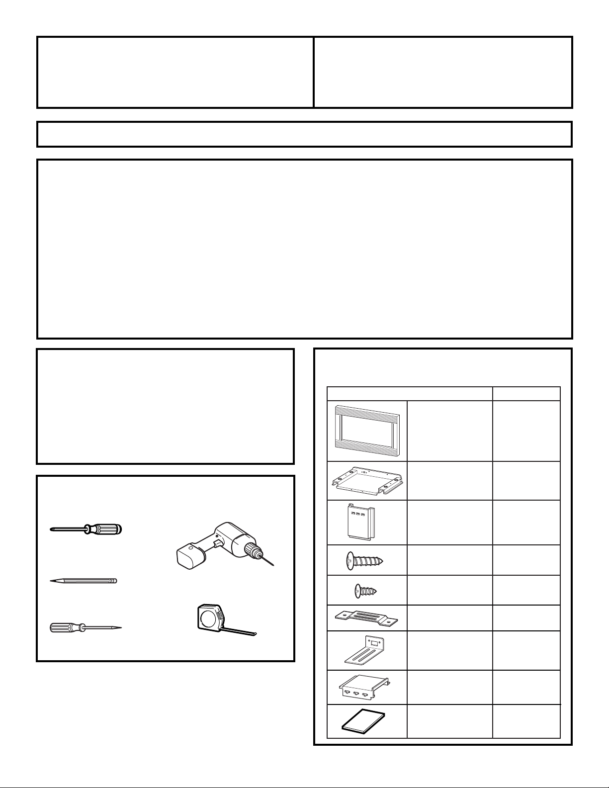
PART QUANTITY
Trim Frame 1
Bottom Duct 1
Side Duct 1
1” Screws 6
(4 required, 2 extra)
1/2” Screws 15
(11 required, 4 extra)
Anti-Tip Bracket 1
Bottom Bracket 1
Upper Duct 1
Template 1
PARTS INCLUDED
Questions? Call GE Answer Center at 800.626.2000
or Visit our Website at:
www.GEAppliances.com
READ CAREFULLY.
KEEP THESE INSTRUCTIONS
.
Installation Built-In Trim Kits
Instructions
JX1827 and JX1830
Read these instructions completely and carefully.
•
IMPORTANT
–
Save these
instructions for local inspector’s use.
•
IMPORTANT
–
Observe all
governing codes and ordinances.
• Note to Installer –Be sure to leave these
instructions with the Consumer.
• Note to Consumer –Keep these
instructions for future reference.
BEFORE YOU BEGIN
• Unplug the microwave oven before attempting
installation of this kit.
• Skill level – Installation of this appliance requires basic
mechanical and electrical skills.
• Completion time – 1-3 hours
• Proper installation is the responsibility of the installer.
• Product failure due to improper installation is not
covered under the Warranty.
• This kit is UL listed for installation alone or over any
General Electric/Hotpoint/RCA single electric wall
oven.
TOOLS YOU WILL NEED
Phillips screwdriver
Pencil
Tape measure
Awl or punch
Drill with
7
⁄64″ bit or #35
1
FOR YOUR SAFETY:
WARNING
–
Before beginning the
installation, switch power off at service panel and lock
the service disconnecting means to prevent power
from being switched on accidentally. When the service
disconnecting means cannot be locked, securely fasten
a prominent warning device, such as a tag, to the
service panel.
Page 2
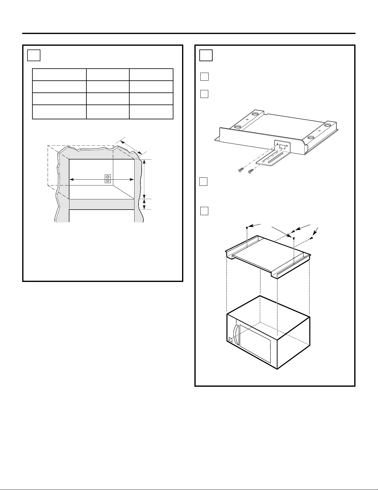
2
CUTOUT DIMENSIONS
1
.
* Min. depth with receptacle outside cabinet 19
1
⁄2″
Min. depth with receptacle inside cabinet 22″
Installation Instructions
Models 27″ 30″
Height 16
3
⁄4″ 163⁄4″
Width 25
1
⁄2″ 251⁄2″
Depth (min.)* 19
1
⁄2″ or 22″ 191⁄2″ or 22″
On 27″ models, allow 1″ at the top, 11⁄16″ on the sides
and 1
3
⁄8″ at the bottom for overlap of the Trim Frame
over the edges of the cutout.
On 30″ models, allow 1″ at the top, 23⁄16″ on the sides
and 1
3
⁄8″ at the bottom for overlap of the Trim Frame
over the edges of the cutout.
Depth
Height
3″ Min.
Width
INSTALL BOTTOM BRACKET AND BOTTOM DUCT
2
.
Disconnect the microwave oven before proceeding
with the installation.
Fasten the bottom bracket to the bottom duct by
using two
1
⁄2″screws.
Remove any loose items inside the microwave
oven, including the turntable and turntable
support. Carefully turn the microwave upside
down.
Install bottom duct with four
1
⁄2″screws as shown.
A
C
B
D
Front
Rear
1
⁄2″ Screws (2)
Screws
Screws
Microwave Oven Upside Down
Page 3

3
Installation Instructions
INSTALL THE ANTI-TIP BRACKET
3
.
Fold or cut the front edge of the template, along
the front guide line. Place the template flush along
the front edge of the cutout floor, aligning the
center line of the template with the center line of
the cutout floor. Mark the center positions with an
awl or center punch for the anti-tip bracket
location as shown.
Remove the template and drill two holes for the
anti-tip bracket.
Install the anti-tip bracket onto the cutout floor
using two
1
⁄2″screws.
A
B
C
Cutout Floor
1
⁄2″ Screws (2)
Anti-Tip Bracket
INSTALL SIDE DUCT AND UPPER DUCT
4
.
Connect the side duct to the upper duct as shown.
1. Insert projecting tabs of the upper duct into the
holes of the side duct.
2. Bend the tabs up with caution as shown.
NOTE: Remove any oil or dirt on the surface of the
microwave oven before the ducts are attached.
Set the microwave upright, being careful not to
bend the front flange. Remove the one existing
screw from the left side of the microwave oven.
Peel off the backing of the double sided tape.
Carefully position the side duct and upper duct
assembly on the microwave cabinet, aligning with
the bottom screw hole. Press down firmly on the
ducts. Fasten the duct assembly to the left side of
the cabinet with the screw removed above.
B
A
(2)
C
Existing Screw (1)
(1)
Upper Duct
Side Duct
3 Tabs
3 Holes
Page 4

4
Installation Instructions
INSTALL MICROWAVE OVEN INTO CABINET
5
.
Slide the microwave oven part way into the cabinet
opening.
Plug in the microwave oven.
Bottom bracket must be flat to the cutout floor to
engage correctly with the anti-tip bracket as shown.
Carefully slide the microwave back, making sure
the power cord is not mashed or cut.
Center the microwave oven within the cutout
opening and slide the microwave oven in place,
engaging the anti-tip bracket.
Ensure the microwave oven is accurately centered.
Drill pilot holes through the positioning flange
and then install three
1
⁄2″screws at the front of the
bottom duct as shown.
A
B
C
Place the trim frame over the microwave oven.
Make sure the trim frame is level and the
microwave oven is centered within the trim frame.
Mark four center positions through the four
mounting holes of the trim frame.
NOTE: Center the trim frame equally on all four sides.
Remove the trim frame and drill four pilot holes.
Attach the trim frame by using four screws.
A
B
C
D
Anti-Tip Assembly
Bottom Duct
1
⁄2″ Screw
Bottom Bracket
Anti-Tip
Bracket
D
E
Cutout Opening
Positioning Flange
1
⁄2″ Screw
F
INSTALLING THE TRIM FRAME
6
.
Pilot Hole
Cutout Opening
Mounting Hole
Trim Frame
1″ Screw
Your trim kit is now fully installed. Replace any
loose items that were removed from the inside of
the microwave oven.
Keep these installation instructions for future
reference.
Replace house fuse or close circuit breaker.
A
B
REPLACE ANY LOOSE ITEMS
7
.
Part No. 245B1790P075
Pub. No. 31-20936-1
3828W5U0053 12-00 JR Printed in Korea
C
 Loading...