

Page 1
Installation Bump-Out Kit
Instructions
JX15BUMP
For 15” Deep Cabinets
IMPORTANT:
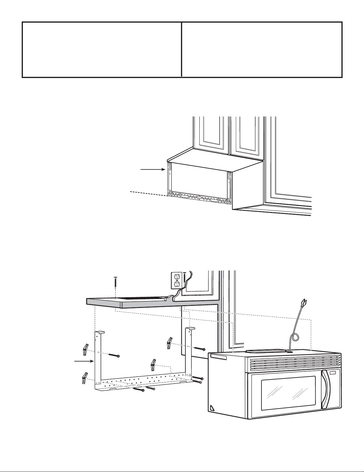
Use the existing mounting bracket that comes with your OTR Microwave to identify location for the Bump Out Kit.
Place the original bracket on the wall according to
installation instructions from the OTR Microwave to
determine where to place the Bump Out Kit Bracket.
Existing Mounting Bracket
from OTR Microwave
Mark lowest edage of bracket
Place the Bump Out Kit Bracet in place of existing bracket location making sure that the bottom edge lines up.
Bump-Out Kit
Bracket
49-40719-1 03-15 GE
Page 2
Installation Instructions
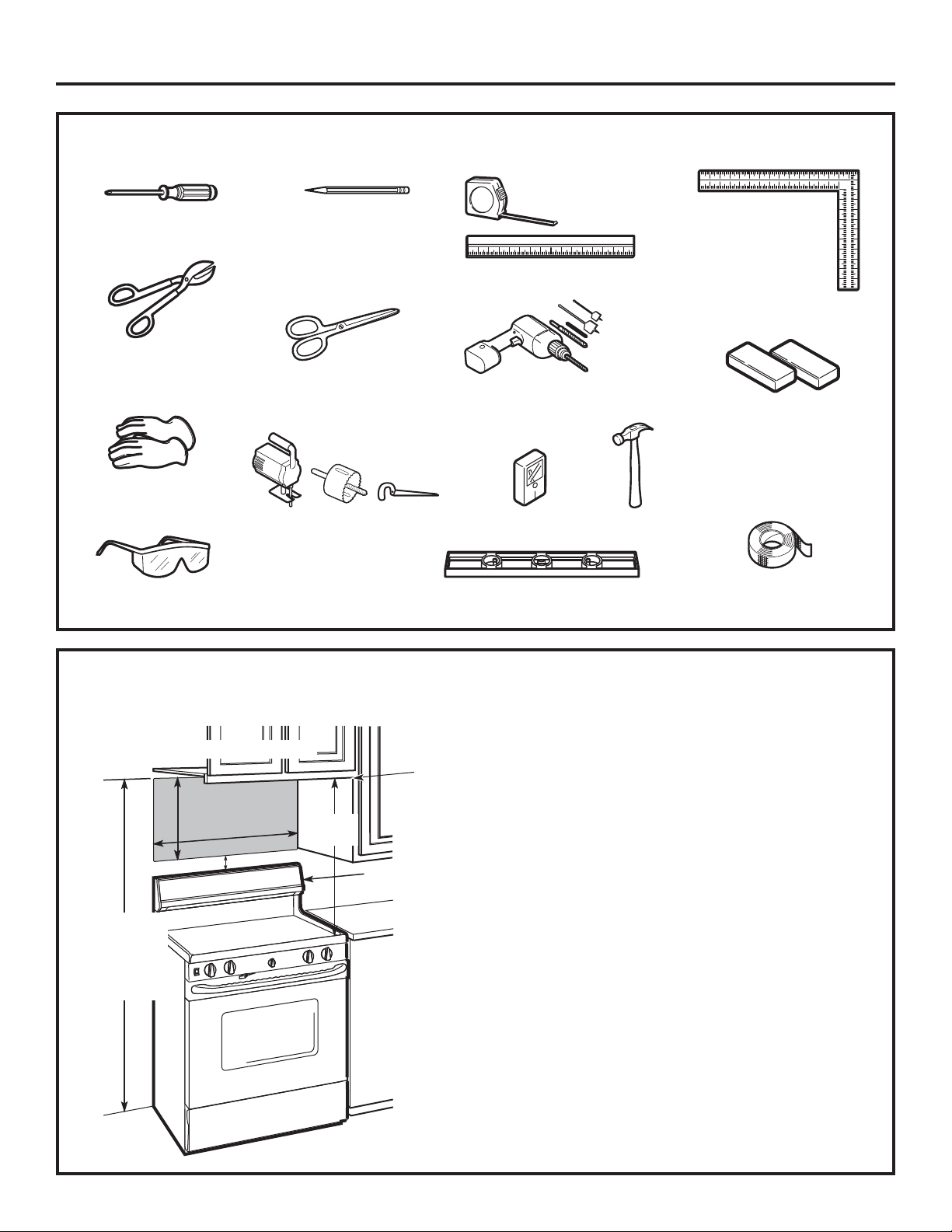
TOOLS YOU WILL NEED
#1 and #2 Phillips screwdriver
Tin snips (for cutting
damper, if required)
Gloves
Scissors
(to cut template, if necessary)
Pencil
Ruler or tape
measure and
straight edge
Electric drill with
1
ø2” and 5ø8” drill bits
3
ø16” , 7ø16”, 3ø8”,
Carpenter square
(optional)
Filler blocks or scrap
wood pieces, if needed
for top cabinet spacing
(used on recessed
bottom cabinet
installations only)
Saw (saber, hole or keyhole)
Safety goggles
MOUNTING SPACE
NOTE: Maximum cabinet depth is 15”.
1
16-
ø4”
30
”
2”
66” or more
from the
floor to the
top of the
oven
30”
min.
Backsplash
Stud finder or
Bottom edge
of cabinet
needs to
be 30” or
more from
the cooking
surface
Hammer (optional)
Level
Duct and masking tape
NOTES:
The space between the cabinets must be 30” wide
and free of obstructions.
If the space between the cabinets is greater
than 30”, a Filler Panel Kit may be used to fill
in the gap between the oven and the cabinets.
Your Owner’s Manual contains the kit number for
your model.
This oven is for installation over ranges up to
36” wide.
If you are going to vent your oven to the outside,
see Hood Exhaust Section for exhaust duct
preparation.
When installing the oven beneath smooth, flat
cabinets, be careful to follow the instructions
on the top cabinet template for power cord
clearance.
2
Page 3

Installation Instructions
PLACEMENT OF THE BUMP-OUT BRACKET
1
Find the studs, using one of the following methods:
A.
FINDING THE WALL STUDS
Level line for front overhang
Wall Studs
Center
1
A. Stud finder – a magnetic device which locates nails.
B. Use a hammer to tap lightly across the mounting
surface to find a solid sound. This will indicate a stud
location.
After locating the stud(s), find the center by probing
2
the wall with a small nail to find the edges of the stud.
Then place a mark halfway between the edges. The
center of any adjacent studs should be 16" or 24" from
this mark.
3
Draw a line down the center of the studs.
THE OVEN MUST BE CONNECTED TO AT LEAST ONE
WALL STUD.
OR
ALIGNING THE WALL PLATE
B.
CAUTION: Wear gloves
to avoid cutting fingers
on sharp edges.
Hole Location A
Area E
Hole Location C
Draw a vertical line on the wall at the center of the 30”
1
wide space.
Use mounting plate as the template for the rear wall.
2
Place mounting plate on the wall, making sure that the
tabs are touching the bottom of the cabinet or the level
line drawn for cabinets with front overhang. Line up the
notch and center line on the mounting plate to the center
line on the wall. (If the tabs are not in line with front
overhang, unit will be tilted.)
3
While holding mounting plate with one hand, draw circles
on the wall at holes A, B, C and D (see illustration above) .
Four holes must be used for mounting.
NOTE: Appearance
and shape of the
mounting plate
may vary from your
model.
Draw a
Vertical Line
on Wall from
Center of Top
Cabinet
NOTE: Holes C and D are inside area E. If neither C nor D
is in a stud, find a stud somewhere in area E and draw
a fifth circle to line up with the stud. It is important to
use at least one wood screw mounted firmly in a stud to
support the weight of the oven.
Hole Location B
Hole Location D
Set the mounting plate aside.
Drill holes on the circles. If there is a stud, drill a 3ø16” hole
4
for wood screws. For holes that don’t line up with a stud,
drill a 5ø8” hole for toggle bolts.
NOTE: DO NOT MOUNT THE PLATE AT THIS TIME.
3
Page 4

Installation Instructions
INSTALLING THE BUMP-OUT BRACKET
2
A.
ATTACH THE MOUNTING PLATE TO
THE WALL
Attach the plate to the wall using (2-4) toggle bolts.
At least one wood screw must be used to attach the
plate to a wall stud. NOTE: Use hardware from OTR
packaging.
Remove the toggle wings from the bolts.
1
Insert the bolts into the mounting plate through the
2
holes designated to go into drywall and reattach the
toggle wings to 3ø4” onto each bolt.
To use toggle bolts:
Spacing for
Toggles More Than
Wall Thickness
Mounting
Plate
Place the mounting plate against the wall and insert
3
the toggle wings into the holes in the wall to mount
the plate.
NOTE: Before tightening toggle bolts and wood screw,
make sure the tabs on the mounting plate touch the
bottom of the cabinet when pushed flush against the
wall and that the plate is properly centered under the
cabinet.
CAUTION: Be careful to avoid pinching fingers between
the back of the mounting plate and the wall.
Tighten all bolts. Pull the plate away from the wall to
4
help tighten the bolts.
Toggle Wings
Toggle
Bolt
Wall
Bolt End
4
 Loading...