

Page 1
Microwave Oven
Installation instructions
for your new
CAUTION:
• Before you begin—Read these instructions, Use & Care Manual and Important Safety Instructions
completely and carefully.
• This Kit is for use on models: JE1530GW, JE1540AW/GW/WW, JE1550GW/GY/WW/WY, JES1533BW, JES1534BW,
JES1634WA/BB/WB, JE1640GA/WA/AB/GB/WB, JE1650AA/GA/WA, JE1660GA/SA/WA/GB/WB/SB, ZE1660SA/SB.
• This kit can be installed alone or over any General Electric/Hotpoint/RCA single electric wall oven.
• Do not alter or modify any part of this kit or the oven.
• Observe all governing codes and ordinances.
• Oven must be plugged into a properly grounded 3-hole, 120 volt receptacle as required by the
National Electrical Code.
• Unplug the microwave oven before attempting installation of this kit.
• Save these instructions (for Local Inspectors and Future Reference).
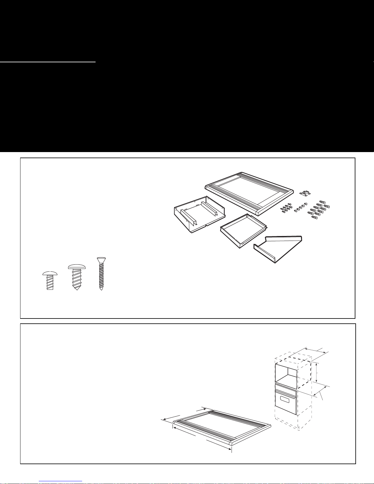
Parts List
1. Base Pan
2. Rear Duct
3. Top Duct
4. Trim Kit Frame
5. 2 Rear Holdown Brackets
Screws A (6 required 2 extra)
B (4 required 1 extra)
C (8 required 2 extra)
Built-In Trim Kits
JX1530MAW, JX1530MBW,
JX1530MWW, JX1530MSA
4
1
2
A
5
B
C
Parts Inventory
Screw A Screw B Screw C
Note: This kit has extra screws to prevent servicemen from spending
extra time locating a replacement in case they lose one during installation.
Cabinet Cutout Dimensions and Specifications
Allow 1-1/2" overlap on the top and bottom edges and 3" overlap on
each side of the cutout for this microwave oven trim kit.
WIDTH HEIGHT DEPTH
24-1/8"±1⁄ 8" 17-9/16"±1⁄16" 19" Min. receptacle outside cutout
21" Min. receptacle inside cutout
120 volt—60 Hertz grounded power receptacle.
For Installation Above a Built-In Oven
Microwave oven should be installed on a
3⁄8" plywood base and supported by 2x4 or
1x2 equivalent runners on all sides. Base
must be capable of supporting a minimum
of 100 lbs.
19-3/4"
29-3/4"
3
24-1/8"±1/8"
17-9/16"±1/16"
21" Min.
receptacle
in cabinet
19" Min.
receptacle
outside
cabinet
Page 2
Tools Needed
2 Phillips head screwdrivers (#1 & #2)
Drill and 3/32" drill bit
Centerpunch or nail
Pencil and ruler
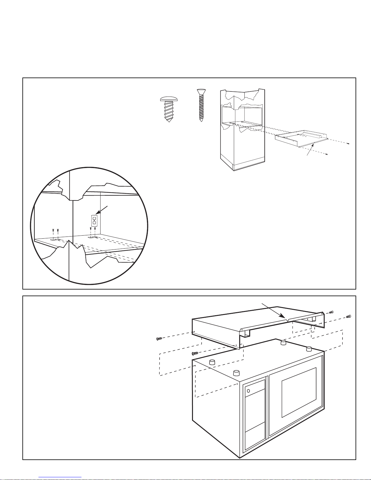
Installation Procedure
Step 1
Locating and Installing Rear
Holddown Supports
Set Base Pan (1) into the front cabinet
microwave oven cutout and center it right
and left. Push back until front flange is
against cabinet front wall. The V-notch in
the Base Pan front flange can be used to
help center the Base Pan. Bore two 3/32"
diameter holes into the cabinet base
120V/60 Hertz
Grounded Power
Outlet
Drive two Screws
(C) into the Base
Pan front flange to
hold in place
temporarily.
Screw CScrew B
V Notch
supporting structure using the two holes in the Base Pan front
flange as your guide (center the drill in the base holes keeping
the front flange centered and tight against the cabinet front
wall).
Slide the two Rear Holddown Brackets (5) from the rear into
the slots in the Base Pan. The tongues of the Rear Holddown
Brackets should be sticking into the base, be centered in the slot,
and be into the slot as far as it will go. Mark and drill four 3/32"
diameter holes. Mount the Rear Holddown Brackets using four
Screws (B). Both Rear Holddown Bracket tongues should now be
centered in the slotted holes in the base and be into the base as
far as they can go.
Remove the two screws in the Base Pan front flange and slide the
Base Pan straight out.
Step 2
Installation of Base Pan
Disconnect microwave oven from receptacle. Remove everything out of the
microwave oven (packing, glass shelf,
temperature probe, Use & Care books).
Turn the microwave oven upside down.
Remove the four side screws from the
sides of the Microwave Oven cabinet.
Place the Base Pan (1) on the bottom of
the microwave oven and secure it with the
four screws just removed. Turn microwave
oven right side up being careful not to
bend the Base Pan front flange.
V Notch
Page 3

Step 3
Installation of Rear Duct
Note: It is easier to start all screws before
tightening any screw.
Remove one screw (D) on the back of the
microwave oven. Retain screw.
Install Rear Duct by inserting the bottom
flange between the oven and the back of
the Base Pan. The Rear Duct should be as
far to the right as possible. Drive two
screws (A) through the Base Pan and into
the Rear Duct bottom flange. Drive the
one screw (D) previously removed into
original holes on the side flanges. Drive
one screw (A) into the microwave oven.
Step 4
Installation of Top Duct
Slide the Top Duct (3) from the front
toward the Rear Duct. The partition
extending out from the Top Duct should
slide into the Rear Duct. Drive the two
Screws (A) through the Rear Duct into
the Top Duct. Drive one Screw (A)
through the side of the Rear Duct into the
partition extending from the Top Duct.
Screw A
Screw A
Screw D
Screw D
Screws A
Screws A
Step 5
Installation of the Microwave Oven
Plug the power cord into the wall receptacle. Slide the microwave oven assembly
gently into the cabinet using care not to
pinch the power cord, and to keep it
centered as it slides back to where the
holddown bracket’s tongue goes through
the rear slots. The unit should now be
centered right to left in the opening and
the Base Pan front flange tight against the
cabinet. Drive two screws (C) through the
Base Pan front flange into the holes
initially drilled. Bore two 3/32" dia. holes
in the cabinet using the top duct flange
holes to locate. Drive two (C) screws in
top duct flange.
Screw A
C
L
V Notch
Screws C
Screw C
Screws C
Page 4

Step 6
Installing the Trim Kit Frame
1. Using the Trim Kit Frame (4) as a
template (and with the microwave oven in
position and secured), center the Trim Kit
Frame around the microwave oven, make
sure the vents point downward. See illustration. Mark the four holes on the side
trim.
2. Remove the Trim Kit Frame.
3. Center punch and drill 3/32" dia. pilot
holes per their hole center marks for the
mounting screws.
4. Position the Trim Kit Frame around the
Oven and secure it with 4 screws (C). Use
the smaller Phillips head screwdriver (#1)
to prevent burring the Phillips head.
The vents on the trim kit frame should
point downward.
For Replacement Installation
If this kit is replacing a JX14, JX16 or JX38
kit, the cutout may be too wide for the trim
screws. If the opening is too wide, the
installer should reduce the opening to 24"
wide by installing wood strips or cleats on
each side to accept the mounting screws.
Wall
Installation
Mark
Mark
Mark
Top
Vent
Vents on top and
bottom should point
downward
Bottom
Vent
CAUTION: Do not overtighten screws
since it can cause misalignment of top/
side strips.
Screw C
Trim Kit Frame
Mark
Part No. 245B1790P071 (2)
Pub. No. 31-1168 (2)
SPECIFICATIONS SUBJECT TO CHANGE WITHOUT NOTICE
(N.D. 313) 2/99
 Loading...