

Page 1
Questions? Call 1.800.561.3344
or Visit our Website at:
GEAppliances.ca
READ CAREFULLY.
KEEP THESE INSTRUCTIONS
.
Installation Built-In Trim Kits
Instructions
JX1124STC
❒
BEFORE YOU BEGIN
FOR YOUR SAFETY:
WARNING –
Before beginning the
installation, switch power off at service panel and lock
the service disconnecting means to prevent power
from being switched on accidentally. When the service
disconnecting means cannot be locked, securely fasten
a prominent warning device, such as a tag, to the
service panel.
1
Read these instructions completely and carefully.
• IMPORTANT – Save these instructions for local
inspector’s use.
•
IMPORTANT – Observe all governing codes and
ordinances.
•
Note to Installer – Be sure to leave these instructions with the
Consumer.
•
Note to Consumer – Keep these instructions for future
reference.
• For easier installation and personal safety, we recommend that
two people install this microwave oven.
WARNING – This oven must be plugged into a properly
grounded 3-hole, 120V receptacle as required by the National
Electrical Code.
• Do not alter or modify any part of this kit or the oven.
• Unplug the microwave oven before attempting installation of
this kit.
• Skill level – Installation of this appliance requires basic
mechanical and electrical skills.
• Completion time – Less than 1 hour
• Proper installation is the responsibility of the installer.
• Product failure due to improper installation is not covered
under the Warranty.
• This kit is cUL listed for installation alone. Not for use adjacent
to (within 2 feet of) any gas or electric range, cooktop or oven.
• This kit is for use on model: JE1140 STC.
PARTS
Number Part Quantity
1 Screw, M4 x 10 4
2 Customer Supplied Cabinet Not Included
3 Microwave Oven Not Included
4 Lower Exhaust Guide 1
5 Screw M4 x 8 7
6 Trim Piece 1
7 Screw M3 x 20 4
8 Upper Exhaust Guide 1
Page 2
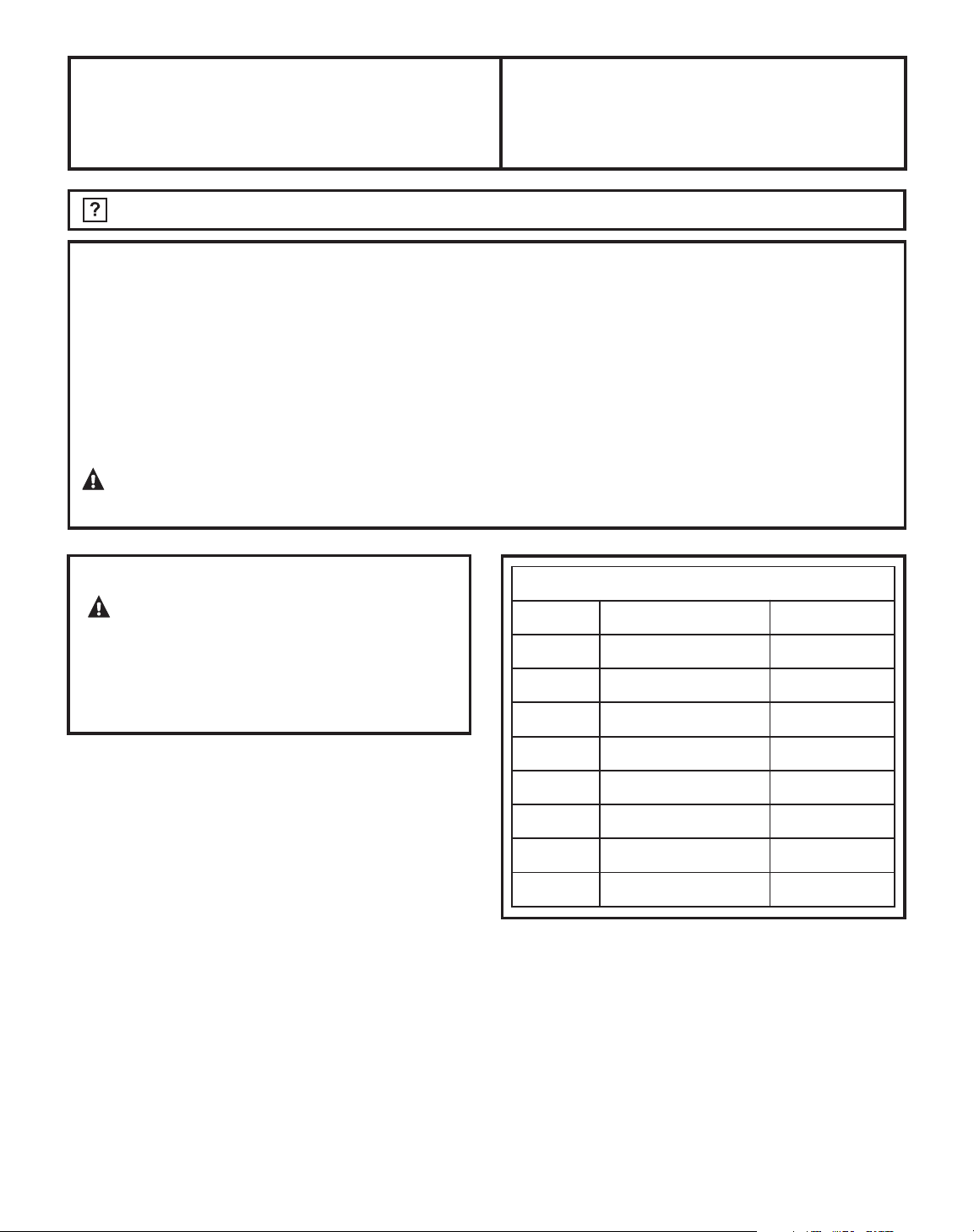
❒
CABINET REQUIREMENTS
1
2
Installation Instructions
Cabinet must comply with these dimensions.
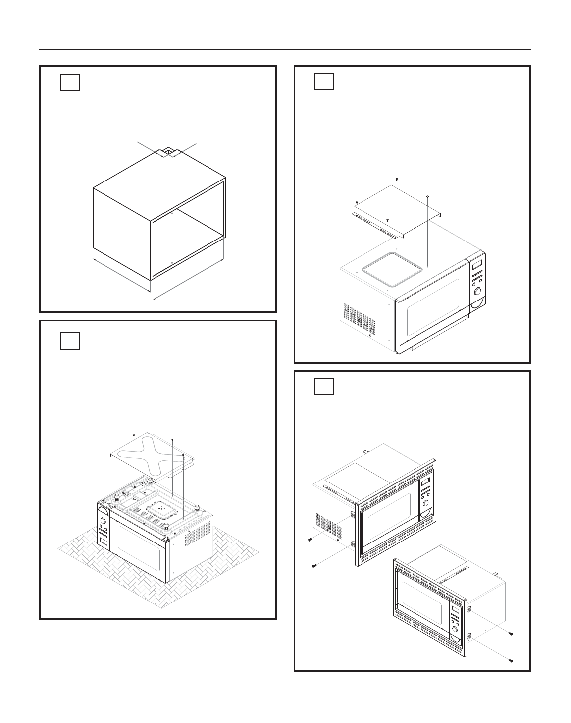
❒
INSTALL UPPER EXHAUST
GUIDE
3
Mount Trim Piece onto the front of the Microwave
and secure on both sides using four M4 x 10 screws,
2 on each side.
❒
INSTALL TRIM PIECE
4
❒
INSTALL LOWER EXHAUST
GUIDE
2
Turn the Microwave upside down and install the
Lower Exhaust Guide using three M4 x 8 screws.
NOTE: Ensure the orientation of the Rear flange is
correct (i.e. Opening pointing forward).
Return the Microwave to its upright position
and install the Upper Exhaust Guide using
four M4 x 8 screws.
NOTE: Ensure the orientation of the Rear flange is
correct (i.e. Opening pointing forward).
2.5”
(100 mm)
-0
+0.08 (2)
2.5”
(100 mm)
17.9” (455 mm) min
14.5” (370 mm)
22” (560 mm)
+0.08 (2)
-0
Page 3

Installation Instructions
Centre the Microwave in the opening, pre-drill 4 holes
through the Trim Piece into the Cabinet then attach
the Microwave/Trim Piece assembly to the Cabinet
using 4 M3 x 20 screws (1 in each corner).
❒
FASTEN THE MICROWAVE
6
Place the Microwave close to the Cabinet opening
and fit the Power Cord (Plug End first) through
the 2.5” x 2.5” (100 mm x 100 mm) opening.
Slide the microwave into the Cabinet and, at the
same time, ensure the Power Cord continues to be
drawn through the opening.
A
B
❒
MOUNT MICROWAVE
5
350A4502P714
29-5792
08-011 ATS
Printed in China
2.5”
(100 mm)
2.5”
(100 mm)
2.5”
(100 mm)
2.5”
(100 mm)
 Loading...