

Page 1
Installation
Overthe Range
Instructions
Microwave Oven
JVM2050,JVM2070
Questions?Call800.GE.CARES(800.432.2737)or Visit,,,,_x_ebsite;,t:GEAppliances.com I
BEFORE YOU BEGIN
Read these instructions completely and carefully.
• IMPORTANT - S_,,ethese
instructions for local inspector's use.
• IMPORTANT - Obse_,'e_,ll
governing codes and ordinances.
• Note to Installer - Be sure to leave these
instructions with the Consumer.
° Note to Consumer - KeeI)these
instructions for future reterence.
° Skill level - Installation of this appliance requires
basic mechanical and electrical skills.
• Proper installation is the responsibility of the installer.
• Product tailure due to improper installation is not
coxered under the _'arrantx.
Fora Spanish version of thismanual, visitour Websiteat GEAppliances.com.
Para consultaruna versionen espa#ol de estemanual de instrucciones,visitenuestrositio
deinternet GEAppliances.com.
READ CAREFULLY.
KEEP THESE INSTRUCTIONS.
Page 2
Installation Instructions
CONTENTS
General information
hnportant Safety Instructions .................................. 3
Electrical Requirements .......................................... 3
Hood Exhaust ...................................................... 4, 5
Damage - Shipment/InstaJlation .............................. 6
Parts Included. ......................................................... 6
Tools You Will Need ................................................ 7
Mounting Space ...................................................... 7
Step-by-step installation guide
Placement of Mounting Plate ............................ 8-10
Removing the Mounting Plate ...................... 8
Finding the _,_lll Studs .................................. 8
Determining _,_all Plate Ix)ration .................. 9
Rerirculating ........................................ 19-22
Attach Mounting Plate to _._._11 .......... 19
Prepm_lfion of Top Cabinet .......... 19
Check Microwave Assembly .......... 20
Adapting Microwave Blower
ti)r Rerirculation ......................... 20, 21
Motmt the Microwave Oveu ..........21, 22
Installing the Charcoal Filter ..............22
Before You Use Your Microwave .......................... 23
Aliguiug the Wall Plate.. ............................. 10
Installation Types.. ................................ 11-22
[]Outside Top ............................
Attach Mortaring Plate to WM1 ....... 12
Preparation of Top Cabinet .......... 13
Checking tier Proper Damper
()peration ............................................ 13
Mount the Microwave Oven .......... 13
Ac!iust the Exhaust Adaptor .......... 14
Connerting Durtwork .......................... 14
_ Outside Back Exhaust 15-18
Preparing Rear _,Vall for
Outside Bark Exhaust .......................... 15
Remove Exhaust Adaptor .................... 15
Attarh Motu_ting Plate to _'lll ....... 16
Prepm_ltion of Top CaMnet .......... 16
Adapting Microwave Blower
tor Outside Back Exhaust ............... 16, 17
Exhaust
12-14
Mount the Microwave Oven .......... 18
2
Page 3
Installation Instructions
IMPORTANT SAFETY INSTRUCTIONS
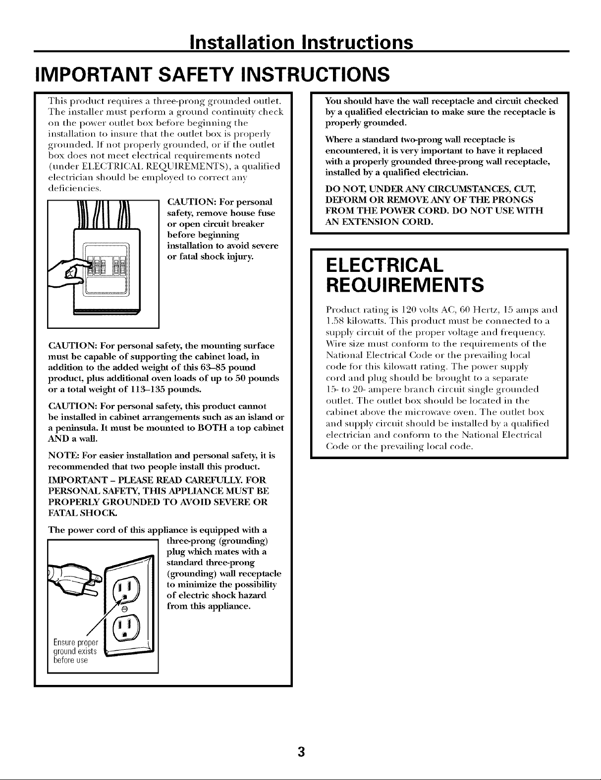
This product requires a three-prong grounded outlet.
The installer must i)erlmm a ground continuity check
on the power outlet box belm'e beginning the
installation to insure that the outlet box is properly
grounded. If not properly grounded, or if the outlet
box does not meet electrical requirements noted
(under EI,ECTRICAI, REQUIREMENTS), a qualified
electrician should be employed to correct any
deficiencies.
CAUTION: For personal
safety, remove house fuse
or open circuit breaker
before beghnth_g
installation to avoid severe
or fatal shock injury.
CAUTION: For personal safety, the mounting surface
must be capable of supporting the cabinet load, in
addition to the added weight of this 63-85 pound
product, plus additional oven loads of up to 50 pomads
or a total weight of 113-135 pounds.
CAUTION: For personal safety, this product cmmot
be installed in cabinet arrm_gements such as an islm_d or
a peninsula. It must be mounted to BOTH a top cabinet
AND a wall.
NOTE: For easier installation mad personal safety, it is
recmmnended that two people install this product.
IMPORTANT - PLEASE READ CAREFULLY. FOR
PFRSONAL SAFETY, THIS APPLIANCE MUST BE
PROPERLY GROUNDED TO AVOID SEVERE OR
FATAL SHOCK.
You should have the wall receptacle m_d circuit checked
by a qualified electricima to make sure the receptacle is
properly grom_ded.
Where a standard two-prong wall receptacle is
encomatered, it is very hnportant to have it replaced
with a properly grounded three-prong wall receptacle,
installed by a qualified electricima.
DO NOT, UNDER ANY CIRCUMSTANCES, CUT,
DI_)'ORM OR REMOVE ANY OF THE PRONGS
FROM THE POWER CORD. DO NOT USE WITH
AN EXTENSION CORD.
ELECTRICAL
REQUIREMENTS
Product rating is 120 volts AC, 60 Hertz, 15 amps and
1.58 kilowatts. This product must be connected to a
suI_ply circuit of the proper voltage and fl'equency.
Wire size ulust conlorin to the requirements of the
National Electrical Code or the i_revailing local
code tier this kilowatt rating. The power sui_ply
cord and phtg should be brought to a separate
15- to 20- ampere branch circuit single grounded
outlet. The outlet box should be located in the
cabinet above the microwave oven. The outlet box
and SUl_ply circuit should be installed by a qualified
electrician and conlin'm to the National Electrical
Code or the prewfiling local code.
The power cord of this applim_ce is equipped with a
three-prong (grounding)
plug which mates with a
staaldaxd three-prong
(grounding) wall receptacle
to mh_hnize the possibility
of electric shock hazard
from this appliance.
Ensureproper
groundexists
beforeuse
3
Page 4
Installation Instructions
HOOD EXHAUST
NOTE: Read these next two pages only if you plma to vent your exhaust to the
outside. If you plan to recirculate the air back into the room, proceed to page 6.
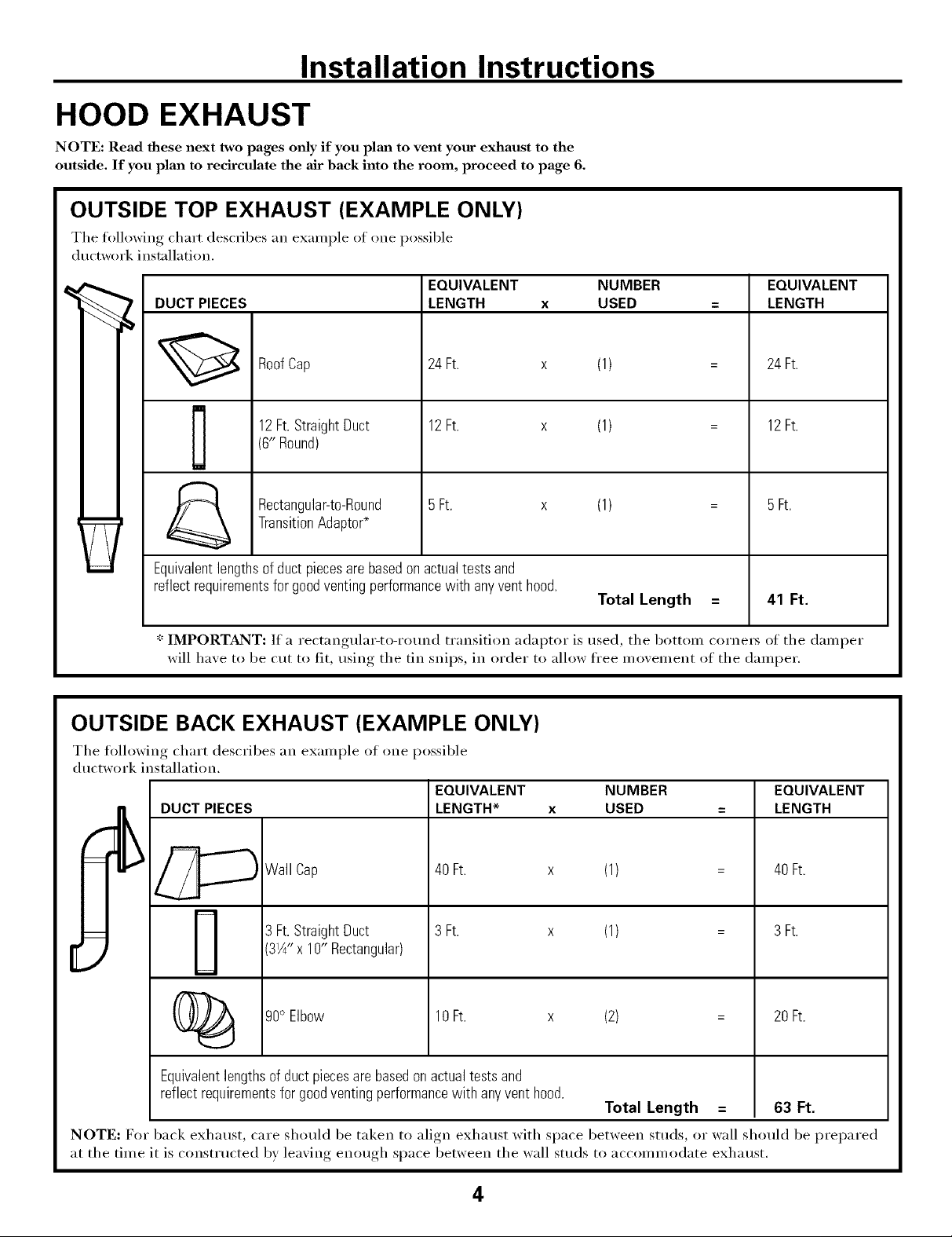
OUTSIDE TOP EXHAUST (EXAMPLE ONLY)
The following chart describes an example ot one possible
ductwork installation.
EQUIVALENT NUMBER
DUCT PIECES
12Ft.StraightDuct 12Ft. x
RoofCap 24 Ft. x
(6" Round)
TransitionAdaptor*
Rectangular-to-Round 5Ft. x
Equivalentlengthsof duct piecesare basedon actualtestsand
reflectrequirementsfor goodventingperformancewith anyventhood.
* IMPORTANT: If a rectangula>to-round transition adaptor is used, the bottom cornet_ of the damper
will haxe to be cut to fit, usin,,. _ the tin snips, in order to allow free moxement of the damper.
LENGTH x USED
OUTSIDE BACK EXHAUST (EXAMPLE ONLY)
(1)
(1)
(1)
Total Length
EQUIVALENT
LENGTH
24 Ft.
12Ft.
5Ft.
41 Ft.
The following chart describes an example ot one possible
ductwork installation.
EQUIVALENT NUMBER
LENGTH* x USED
_Wall Cap
DUCT PIECES
[
(_ 90° Elbow
Equivalent lengths of duct pieces are based on actual tests and
reflect requirements for good venting performance with any vent hood.
NOTE: For back exhaust, care should be taken to align exhaust with space between studs, or wall should be prepared
at the time it is const_ ucted by leaving enough space between the wall studs to accommodate exhaust.
3 Ft.StraightDuct
3W' x 10" Rectangular)
40Ft. x (1)
3 Ft. x (1)
10Ft. x (2) =
Total Length = 63 Ft.
EQUIVALENT
LENGTH
40Ft.
3 Ft.
20Ft.
4
Page 5
Installation Instructions
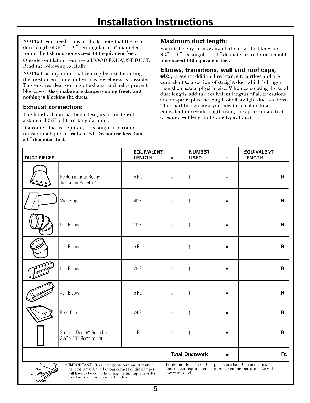
NOTE: If you need to install ducts, note that the total
duct length of 3¼" x ] O" rectangular or 6" (liameter
round duct should not exceed 140 equivalent feet.
Outside ventilation requires a HOOD EXHAUST DUCT.
Read the following careflflly.
NOTE: It is important that venting be installed using
the most direct route and with as few elbows as possible.
This ensm'es clear venting of exhaust and helps prevent
blockages. Also, make sure dampers swing freely and
nothing is blocking the ducts.
Exhaust connection:
The hood exhaust has been designed to mate with
a standard 3Vt" x 10" rectangular duct.
If a round duct is required, a rectangula>to-rotmd
transition adaptor nlust be used. Do not use less than
a 6" diameter duct.
EQUIVALENT NUMBER EQUIVALENT
DUCT PIECES LENGTH x USED = LENGTH
Rectangular-to-Round 5Ft. x ( ) = Ft.
Transition Adaptor*
Maximum duct length:
For satisfi_ctorv air movement, the total duct length of
3¼" x l 0" rectangular or 6" diameter round duct should
not exceed 140 equivalent feet.
Elbows, transitions, wall and roof caps,
etc., present additional resistance to airflow and are
equiwflent to a section of straight duct which is longer
than their actual physical size, When calculating the total
duct length, add the equiwflent lengths of all transitions
and adaptors plus the length of all straight duct sections.
The chart below shows you how to calculate total
equi\_flent ductwork length using the approximate feet
of equivalent length of some typical ducts.
Wall Cap 40 Ft. x ( ) = Ft.
()_ 90° Elbow 10 Ft. x ( ) = Ft.
@ 45° Elbow 5Ft. x ( ) = Ft.
90° Elbow 25 Ft. x ( ) = Ft.
45° Elbow 5Ft. x ( ) = Ft.
Roof Cap 24 Ft. x ( ) = Ft.
Straight Duct 6" Roundor 1 Ft. x ( ) = Ft.
3W' x 10" Rectangular
Total Ductwork = Ft.
adaptor is used, the bottom comers of th( damp(l and rel]( ct reqtfir( m( nls for good v( riling performanc( with
xdll hax( to b( (:Ill to fit, using the lin snips, in ordel any vent hood.
* IMPORTANT: If' a r(( tangulal_to-round transition E(ltfival( nl l(ngths o[ du(t piec( s are bas(d on aclllal lests
to allm_ free lllOVelllelll of Ihe dalllpel,
5
Page 6
Installation Instructions
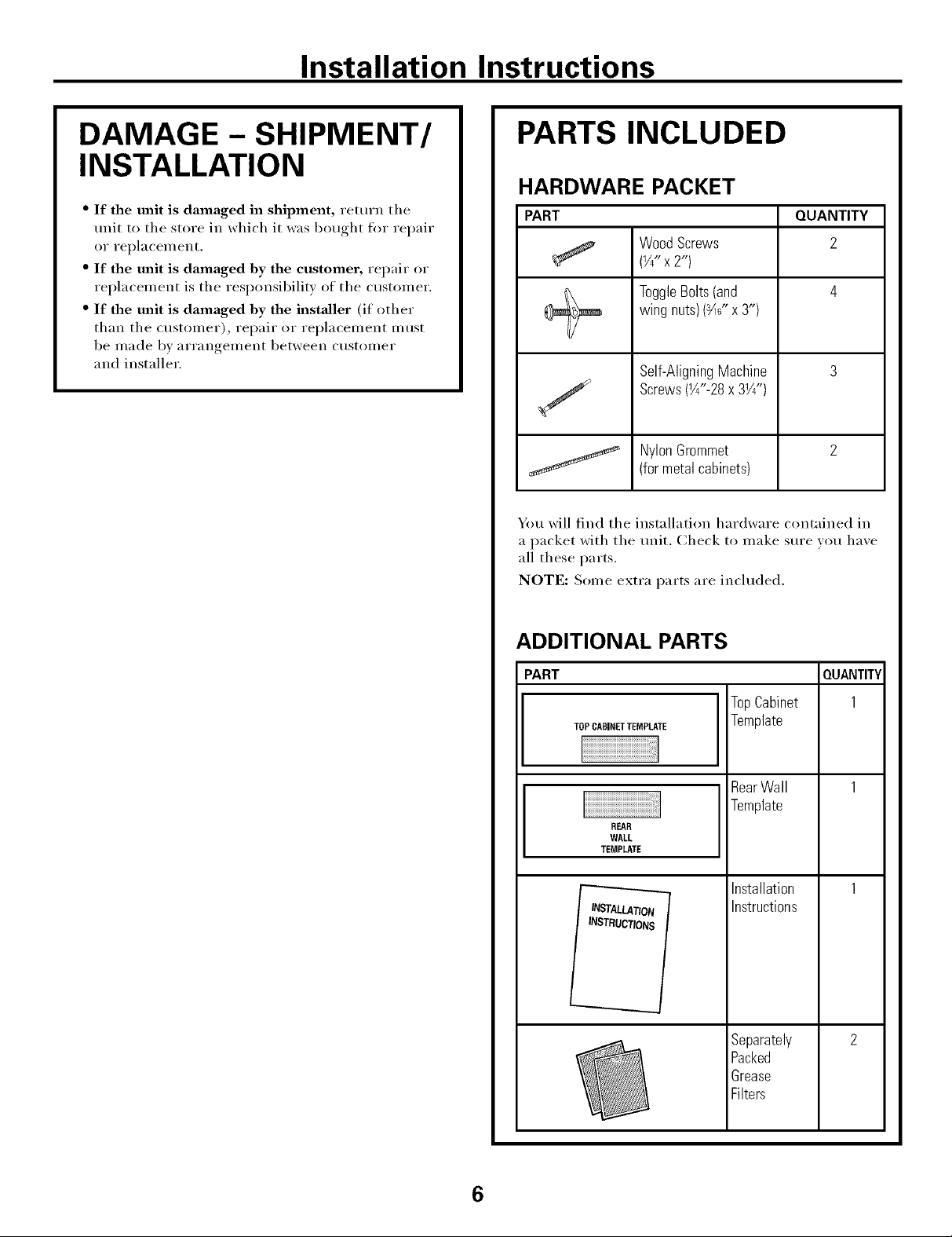
DAMAGE - SHIPMENT/
INSTALLATION
" If the unit is damaged in shipment, return the
unit to the store in which it was bought for repair
or replacement.
" If the unit is damaged by the customer, repair or
replacement is the responsibility of the customer.
" If the unit is damaged by the installer (if other
than the customer), repair or replacement must
be made by arrangement between customer
and installer.
PARTS INCLUDED
HARDWARE PACKET
PART QUANTITY
WoodScrews 2
(¼"x2")
ToggleBolts(and 4
wingnuts)(_F' x3")
Self-AligningMachine 3
Screws(W'-28x 3Y/')
NylonGrommet 2
(formetalcabinets)
You will find the installation hardware contained in
a packet with the trait. Check to make sure you have
all these parts.
NOTE: Some extra parts are included.
ADDITIONAL PARTS
PART
TOPCABINETTEMPLATE
REAR
WALL
TEMPLATE
TopCabinet
Template
RearWall
Template
Installation
Instructions
Separately
Packed
Grease
Filters
QUANTITY
1
6
Page 7
Installation Instructions
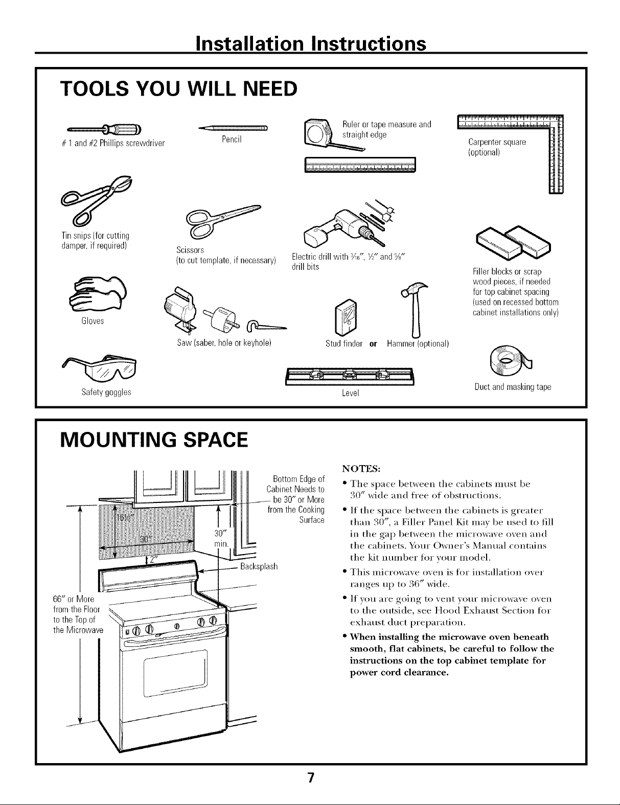
TOOLS YOU WILL NEED
# 1and#2Phillipsscrewdriver
Tinsnips(forcutting
damper,if required)
Gloves
Scissors
(to cut template, if necessary)
Pencil
Rulerortapemeasureand
t edge
Electric drill with ¾_", V/" and %"
drill bits
_r_r_r_i_i_i_i_i_i_1_1_1_r_r_i_i_i_=_=_
(optional)
Fillerblocksor scrap
woodpieces,if needed
fortop cabinetspacing
(usedonrecessedbottom
cabinetinstallationsonly)
Saw (saber, hole or keyhole)
Safety goggles
MOUNTING SPACE
66" or More
fromthe Floor
tothe Topof
the Microwave
BottomEdgeof
CabinetNeedsto
be30" orMore
from the Cooking
Backsplash
Stud finder er Hammer(optional)
Level
NOTES:
• The space betweei] the cabinets must be
30" wide and fl'ee of obstnlctions.
Surface
• If the space betweei] the cabiilets is greater
than 30", a Filler Panel Kit naav be used to fill
iia the gap betweeia the ilaicrowave ()veil aiad
the cabiIlets. Your Owner's Manual coiltaiils
the kit nuinber fl)r your nlodel.
• This nlicrowave oven is fl>I" installation over
ranges up t(> 36" wide,
• If VOII _lI'e going to vent VOtli" illici'ow_lve ()veil
to the outside, see Hood Exhaust Section fl)r
exhaust duct preparation,
• When installing the microwave oven beneath
smooth, flat cabinets, be careful to follow the
instructions on the top cabinet template for
power cord clearmlce.
Duct and masking tape
7
Page 8
Installation Instructions
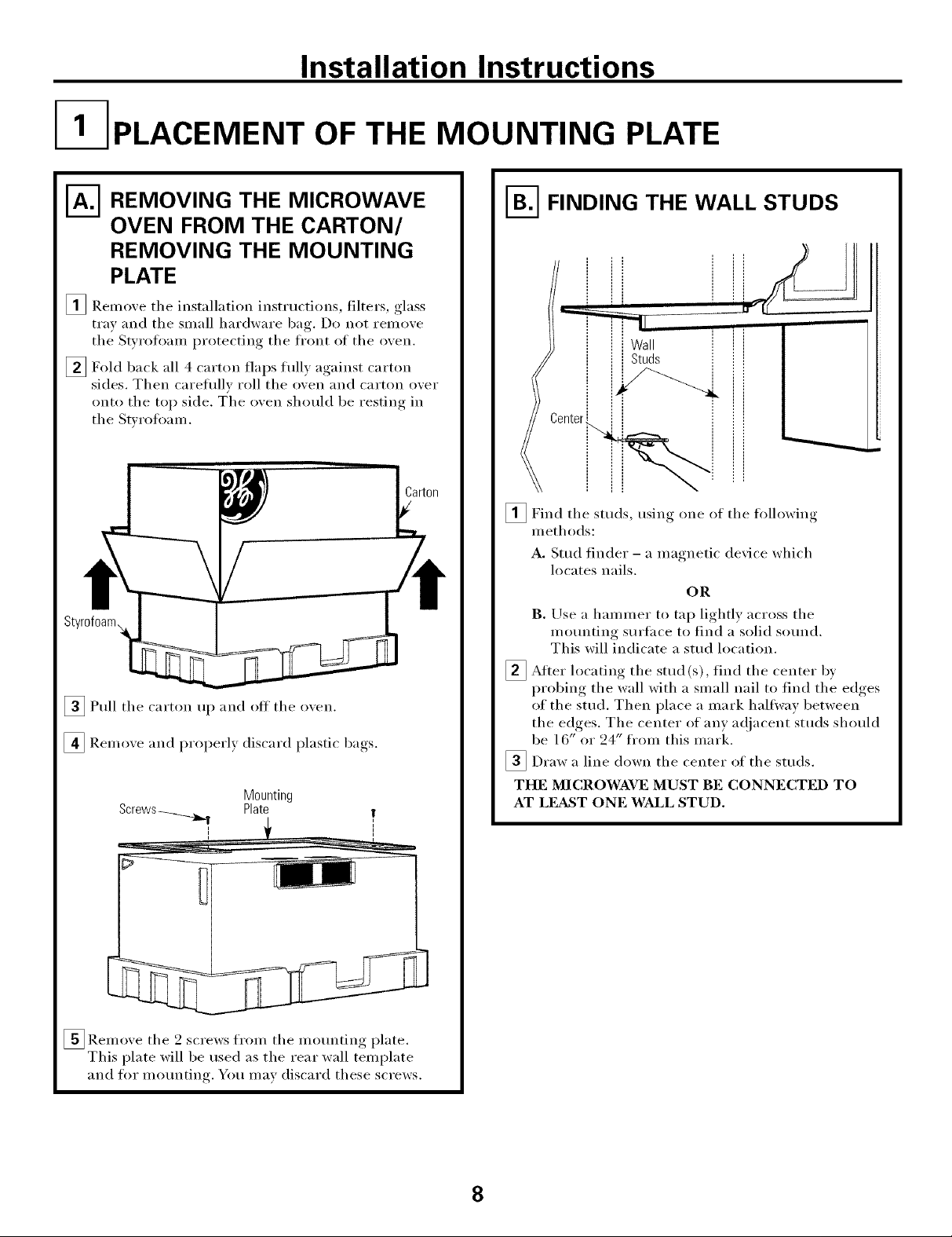
I- PLACEMENT OF THE MOUNTING PLATE
[A--_.REMOVING THE MICROWAVE
OVEN FROM THE CARTON/
REMOVING THE MOUNTING
PLATE
_ Remove the installation instructions, filters, glass
tray and the small hardware bag. Do not remove
the Swrotoam protecting the fl'ont of the oven.
[] Fold back all 4 carton flaps flflly against carton
sides. Then careflflly roll the oven and carton over
onto the top side. The oven should be resting in
the Stvrotoam.
[]Pull the carton up and off the oxen.
[] Remoxe and i)roperly discard plastic bags.
Mounting
Plate
!
i
VB-_FINDING THE WALL STUDS
lc -_ _-_
i liwa, !
enter_
_Find the studs, using one of the following
methods:
A. Stud finder - a magnetic dexice which
locates nails.
OR
B. Use a hammer to tap lightly across the
motmting surface to find a solid sound.
This will indicate a stud location.
_}_ After the stud find the bvlocating (s),
probing the wall with a small nail to find the edges
of the stud. Then place a mark halfway between
the edges, The center of any a(!jacent studs should
be 16" or 24" fl'om this mark.
]Draw a line down the center of the studs.
THE MICROWAVE MUST BE CONNECTED TO
AT LEa_ST ONE WALL STUD.
centeY
[]Remoxe the 2 screws from the motmting )late
This plate will be used as the rear wall template
and for motmting. You max discard these screws.
8
Page 9

Installation Instructions
DETERMINING WALL PLATE LOCATION UNDER YOUR CABINET
Plate position - beneath flat bottom
"*%.
•,,, Mounting PlateTabs
i the Cabinet Bottom
/ ill
At least30", upto36"
Plate position - beneath framed recessed
cabinet bottom
Mounting Plate Tabs
Touching the Back
Frame
III
II 1
III
30" to Cooktop
Plate position - beneath recessed bottom
cabinet with front overhang
Mounting Plate with
Tabs Below Cabinet
Bottom the Same
Distance as the Front
_gDepth
II
Ii
30" to Cooktop
Your cabinets may have decorative trim that interieres
with the microwave installation. I_.emove the decorative
trim to install the microwave i)roperly and to make it
level.
THE MICROWAVE MUST BE LEVEL.
Use a lexel to make sure the cabinet bottom is lexel.
If the cabinets have a fl'ont overhang only, with no
back or side fl'ame, install the mounting plate down
the same distance as the fl'ont overhang depth. This
will keep the microwave level.
_ Measm'e the inside depth ot the fl'ont overhang.
[] Draw a horizontal line on the back wall an equal
distance below the cabinet bottom as the inside
depth of the front overhang.
_For this type of instnllation with fl'ont overhang only,
align the motmting tabs with this hofizontnl line, not
touching the cabinet bottom as described in Step D.
9
Page 10

Installation Instructions
ALIGNING THE WALL PLATE
HoleB /
CAUTION: _ar gloxes
to axoid cutting fingeI_ on
sharp edges.
_Draw a vertical line on the wall at the center of the
30" wide space.
[]Use the momlting plate as the template fin" the rear
wall. Place the momlting plate on the wall, making
sure that tile robs are touching the bottom of the
cabinet or the level line drawn in Step C for cabinets
with front overhmag. Line up the notch mid centerlhae
on the bottom of the mounting plate to the centerlhle
on the wall.
_ While holding the motmting plate with one hand,
draw circles on the wall at holes A, B, C and D
(see illustration above/acmal plate marked with
arrows). Four holes must be used for mounting.
/
NOTE: Holes C and D are inside area E. If neither
C nor D is in a stud, find a stud somewhere in area E
and draw a filth circle to line up with tile stud. It is
important to use at least one wood screw mounted
firmly in a stud to support the weight of the microwave.
Set the mounting plate aside.
Drill holes on the circles. If there is a stud, drill a :_A_,"
[]
hole fin" wood scre_:s. For holes that don't line up with
a stud, drill a _" hole tot toggle bolts.
NOTE: DO NOT MOUNT THE PLATE AT THIS
TIME.
10
Page 11

Installation Instructions
INSTALLATION TYPES
This microwave oven is designed for adaptation to
the following three types of ventilation:
A. Outside Top Exhaust (Vertical Duct)
B. Outside Back Exhaust (Horizontal Duct)
C. Recirculating (Non-Vented Ductless)
OUTSIDE TOP EXHAUST
(VERTICAL DUCT)
/.Outside TopExhaust
Adaptorin Placefor
(Choose A, B or C)
NOTE: This microwave is shii)ped assembled fl>r Outside
Top Exhaust (except for non-vented models). Select the
type of ventilation required for vom" installation and
proceed to that section.
OUTSIDE BACK EXHAUST
(HORIZONTAL DUCT)
[-_ RECIRCULATING
(NON-VENTED DUCTLESS)
11
A Charcoal Filter Accessory
Kit is required for the non-
vented exhaust. (See your
Owner's Manual tot the kit
nmnber.)
Page 12

Installation Instructions
OUTSIDE TOP EXHAUST (Vertical Duct)
INSTALLATION OVERVIEW
A1. Attach Mounting Plate to _\'all
A2. Prepare Top Cabinet
A3. Check Damper Operation
A4, Mount Microwave Oven
A5. A(!j ust Exhaust Adaptor '.
A6, (_onnect Ductwork "
I-_ ATTACH THE MOUNTING
PLATE TO THE WALL
Attach tile plate to tile wall using toggle bolts.
At least one wood screw Inust be used to attach
the plate to a wall stud.
[]Remove tile toggle wings fl'om tile bolts.
[]Insert tile bolts into tile mounting plate
through the holes designated to go into drywall
and reattach the toggle wings to '_A"onto each bolt.
To use toggle bolts:
SpacingforToggles
MoreThanWall
÷l_,.i-_Th ckness
Mounting
Plate:_
nl,
[]Place tile mounting plate against tile wall and
insert tile toggle wings into tile holes in tile wall
to IllO/Int tile plate.
NOTE: Betore tightening toggle bolts and wood
scrm_, make sure tile tabs on tile mounting plate
touch the bottom of the cabinet when pushed
flush against tile wall and that tile plate is properly
centered under the cabinet,
CAUTION: Be careflfl to axoid I)inching, finoers,_
between the back of the mounting plate and the wall,
_ Tighten all bolts, Pull the plate awax from the wall
to hel I) tighten the bolts,
ToggleWings
BoltEnd
12
Page 13

Installation Instructions
I-_ USE TOP CABINET TEMPLATE
FOR PREPARATION OF TOP
CABINET
You need to drill holes fi_r tile top support screws, a
hole large enough for the power cord to fit throu ,h
and a cutout large enouoh_ for the exhaust adaptor.
%
" Read the instructions on tile TOP CABINET
TEMPLATE.
" Tape it tmderneath the top cabinet.
" Drill the holes, tollowing the insnuctions on the
TOP CABINET TEMPLATE.
CAUTION: Wear safety goggles when drilling holes
in tile cabinet bottom.
I-_ CHECK FOR PROPER
DAMPER OPERATION
Exhaust Adaptor
BlowerPlate
(absenton modelsshipped
for recirculationexhaust)
MOUNT THE MICROWAVE
OVEN
FOIl EASIER INSTAI,IATION AND PERSONAI,
SAFETY, WE RECOMMEND THAT TWO PEOPLE
INSTALL THIS MICROWAVE OVEN.
IMPORTANT: Do not grip or use handle
during installation.
NOTE: If your cabinet is metal, use tile nylon
groluu/et _li'O/lnd tile power cord hole to l)revent
cutting of tile cord.
NOTE: We recommend using filler blocks if tile
cabinet fl'ont hangs below tile cabinet bottom shelf.
IMPORTANT: If filler blocks are
not used, case damage may occur from
overtightening screws.
NOTE: When mounting
tile microwave oven_
thread power cord
through hole in bottom of
top cabinet. Kee I) it tight
throughout Steps 1-3. Do
not pinch cord or lit*
oven by pulling cord.
_I,ifl tilt it
iuicrowave,
forward, and hook
slots at back bottom
edge onto [()/lI" lower
tabs of mounting
Damper
0wave
" Place tile microwave in its uI)right position, with tile
top of tile trait facing up.
" This microwave oven may be shil)ped assembled for
top exhaust (adaptor installed) or fl)r recirculation
exhaust (adaptor absent).
" Make sure tape securing damper is removed and
damper pivots easily before mom_ting microwave.
" You will need to make ac!jtlstlnents to assure proper
alignment with your house exhaust duct atter the
microwave is installed.
_Rotate fI'ont of
up against cabinet
bottoI//.
_lnsert a sell=aligning screw through top center
cabinet hole. Temporarily secure tile oven by
turning tile screw at least two full turns atter tile
threads have engaged. (It will be completely
tightened later.) Be sure to keep power cord
tight. Be careful not to pinch the cord, especially
when mounting flush to bottom of cabinet.
o_en
13
Page 14

Installation Instructions
MOUNT THE MICROWAVE
OVEN (cont.)
CabinetFront
CabinetBottomShelf
FillerBlock
to Depth
of Cabinet
-- quivalent
Recess
Self-AligningScrew
MicrowaveOvenTop
_ Attach the microwave oven to the top cabinet.
[] Insert 2 self:aligning screws
through outer top cabinet
holes. Turn two fldl turns on
e_lch screw.
ADJUST THE EXHAUST
ADAPTOR
Open the top cabinet and ac!iust the exhaust adaptor
to connect to tile house duct.
Damper
\ Backof
BlowerPlate _ --\__ Microwave
I I Ill / _ ForFront-to-Backor
" _ I_l/'f /Side-to-Side Adjustment,
Slidethe ExhaustAdaptor
asNeeded
CONNECTING DUCTWORK
HouseDuct
_ Tighten center
screw completely.,
[] Tighten tile outer two screws to tile top of tile
microwave oven. (While tightening screws, hold
tile microwave oven in place against tile wall and
tile top cabinet.
L,
_]nstall filte_3. See the Owner Manualgrease
packed with tile microwave.
S /
[]Extend tile hot/se (h/€t do]vn to connect to
tile exhaust adaptor.
[] Seal exhaust duct joints using duct tape.
14
Page 15

Installation Instructions
OUTSIDE BACK EXHAUST (Horizontal Duct)
INSTALLATION OVERVIEW
B1. Prepare Rear _4]fll
B2. Remove Exhaust Adaptor
B3. Attach Mounting Plate to _'all
B4. Prepare Top Cabinet
B5. A({just Blower
B6. Mount the Microwave Oven
I-_ PREPARING THE REAR WALL
FOR OUTSIDE BACK EXHAUST
Yo// Ileed to tilt _111 l b
outside exhaust.
" Read tile instHIctions on tile REAR "_4M,I,
TEMPI ,ATE.
" Tape it to tile rear wall, lining up with tile holes
previously drilled t_)r holes A and B in the wall
plate.
" Cut the opening, tollowing the instHIctions of the
REAR X_]__I,I,TEMPI,ATE.
O )enin_* in tile rear wall for
REMOVE EXHAUST ADAPTOR
This microwave oven is shii)ped assembled for top
exhaust. You will need tile exhaust adaptor for
installation in the rear wall opening. To remove tile
exhaust adaptor tl"om tile microwave oven:
[] Remove tape securing damper.
_ Remoxe and [] I,ifl off tile
save screw blower plate
that Damper and attached
blower adaptor fl'om
to mici'owa\'e, tile i/lici'owave.
_ Slide exhaust adaptor to one side and remoxe it.
15
Page 16

Installation Instructions
ATTACH THE MOUNTING
PLATE TO THE WALL
ili
: ii
I
I
Attach the plate to the wall using toggle bolts.
At least one wood screw must be used to attach
the plate to a wall stud.
_ Remove the toggle wings fl'om the bolts,
[]Insert the bolts into the motmting plate through
the holes designated to go into drywall and reattach
the toggle wings to :_A"onto each bolt.
To use toggle bolts:
SpacingforTogglesMore
-"-I*-"-i*_ ThanWall Thickness
i
Mounting
Plate
ToggleWings
USE TOP CABINET TEMPLATE
FOR PREPARATION OF TOP
CABINET
You need to drill holes for the top support screws and
a hole large enouoh for the power cord to fit throu ,h
%
" Read the instructions on the TOP CABINET
TEMPI,ATE.
" Tape it tmderneath the top cabinet.
" Drill the holes, following the instructions on the
TOP CABINET TEMPLATE.
CAUTION: Wear safety goggles when drilling holes
in the cabinet bottom.
ADAPTING MICROWAVE
BLOWER FOR OUTSIDE
BACK EXHAUST
B01tEnd
[]Place the motmting plate against the wall and
insert the toggle wings into the holes in the wall
to mount the plate.
NOTE: getOre tightening toggle bolts and wood
scre_, make sure the tabs on the mounting plate
touch the bottom of the cabinet when pushed flush
against the wall and that the plate is properly
centered under the cabinet.
CAUTION: Be careflfl to axoid I)inchin(*_ fingers
between the back of the motmting plate and the wall.
[]Tighten all bolts. Pull the plate away from the wall
to help tighten the bolts.
_ Remoxe and that holds blower motor
to IllicI'owa'_ e,
_._...... Backof
sa'_e sci'ew
BlowerMotor
Microwave
_2 rM°t°r
_ Careflfll) the blower unit. The wirespull
will extend far enough to allow you to a(!iust the
blm_er unit.
BEFORE: EndB
Fan Blade _-_ II_ I ["
Openings ((_,1 [[[:_ [ ]
o/1[
,aoi°,uo
EndA_"__
16
Page 17

Installation Instructions
ADAPTING MICROWAVE
BLOWER FOR OUTSIDE
BACK EXHAUST (cont.)
_Roll the blower unit 90 ° st) that fan blade
oi)enings, are lacing, the front of the microwaxe.
BeforeRolling After Rolling
Microwave
_ (;entl) the wire the between the
two tabs on the top of the blower so the wire is
behind the tabs.
slip through
BeforeRerouting After Rerouting
gap
Microwave
] (;uide the wire down into the blower )eniw,
so it rests securely in front of the blower,
] Secure the blower unit to the microwaxe with
the screw from Step 1.
_, BlowerPlate
o
Backof
Microwave
_SNc;:; r M°t°r
_ Rotate blower trait com_terclockwise 180 °.
BeforeRotation
Microwave
_ Place the blower unit back into the I)ening.
AFTER: Fan Blade
Openings Facing Back,
End
After Rotation
0
I
Microwave
_ Replace the blower in theplate position
as before with the screw.
_ Attach the exhaust the of theadaptor
o_en b) sliding it into the guides at the top
center of the back of the oxen.
Adaptor
iGuide
SaUle
to
i'eaY
CAUTION: Do not pull or stretch the blower refit
wiring. Make sure the wires are not pinched,
NOTE: The blower unit exhaust
openings should match exhaust openings
on rear of microwave oven.
17
Page 18

Installation Instructions
MOUNT THE MICROWAVE
OVEN
FOR EASIER INSTALIATION AND PERSONAL
SAFETY, WE RECOMMEND THAT TWO PEOPLE
INSTALL THIS MICROWAVE OVEN.
IMPORTANT: Do not grip or use handle
during installation.
NOTE: If vour cabinet is metal, tlse tile nvlon
gi'oi/lulet _lI'()/]nd tile poweI" coi'd hole to prevent
cutting of tile cord.
NOTE: We recommend using filler blocks if tile
cabinet front hangs below the cabinet bottom shell
IMPORTANT: If filler blocks are
not used, case damage may occur from
overtightening screws.
NOT]?:: When motmting
tile ulici'owave oven,
thread power cord
through hole in bottom of
top cabinet. Keep it tight
throughout Steps 1-3. Do
not pinch cord or lift
oven by pulling cord.
[]I,ifl microwave, it
fin'ward, and hook
slots at back bottom
edge onto Ábur lower
tabs of motmting
tilt
[]Insert a sell=aligning screw through top center
cabinet hole. Temporarily secm'e the oven by
turning tile screw at least two full turns after tile
threads have engaged. (It will be completely
tightened later.) Be sure to keep power cord
tight. Be careful not to pinch the cord, especially
when momating flush to bottom of cabinet.
Cabinet Front
CabinetBottomShelf
FillerBlock
to Depth
ofCabinet
T quivalent
Recess
Self-AligningScrew
Microwave OvenTop
_ Attach tile microwave oven to tile top cabinet.
[] Insert 2 self:aligning screws
through outer top cabinet
holes. Turn two flfll turns on
each screw.
[]Rotate fi'ont of
up against cabinet
bottoul.
_ Tighten center
screw completel}.
[] Tighten tile outer two screws to tile top of tile
microwave oven. (While tightening screws, hold
the microwave oven in place against the wall and
the top cabinet.)
oxen
_ Install grease filters. See tile Owner's Manual
packed with tile microwaxe.
18
Page 19

Installation Instructions
RECIRCULATING (Non-VentedDuctless)
INSTALLATION OVERVIEW
C1. Attach ]Vhmnting Plate to Wall
C2. Prepare Top Cabinet
C3. Check Microwave Assembly
C4. At!just Blower
C5. Mount the Microwave Oven
C6. Install Charcoal Filter
I
I
/°"
/
I-_ ATTACH THE MOUNTING
PLATE TO THE WALL
[
_OOOoooOoo*Oo
\ =
Attach the plate to the wall using toggle bolts.
At least one wood screw must be used to attach
the plate to a wall stud.
_ Remove the toggle wings from the bolts.
_ Insert the bolts into the motmting plate through
the holes designated to go into drywall and
reattach the toggle wings to '_A"onto each bolt.
To use toggle bolts:
SpacingforToggles
MoreThanWall
+l_-4.--Th ckness
ToggleWings
Mounting
Plate_
_ Place the motmting plate against the wall and
insert the toggle wings into the holes in the wall
to mount the plate.
NOTE: Betore tightening toggle bolts and wood
scre_, make sure the tabs on the mounting plate
touch the bottom of the cabinet when pushed flush
against the wall and that the plate is properly
centered trader the cabinet.
CAUTION: Be careflfl to axoid I)inching, fingers,
between the back of the motmting plate and the wall.
_ Tighten all bolts. Pull the plate awm from the wall
to help tighten the bolts.
USE TOP CABINET TEMPLATE
FOR PREPARATION OF TOP
CABINET
You need to drill holes for the top support screws and
a hole large enow,h for the power cord to fit throuoh
L
" Read the instructions on the TOP CABINET
TEMPI,ATE.
" Tape it tmderneath the top cabinet.
" Drill the holes, fi_llowing the instiuctions on the
TOP CABINET TEMPLATE.
BoltEnd
CAUTION: XArear satety goggles when drilling holes
in the cabinet bottom.
19
Page 20

Installation Instructions
CHECK MICROWAVE ASSEMBLY
Exhaust Adaptor (absent
on models shipped tot
recirculation exhaust)
Microwave
" Place tile microwave in its upright position, with tile
top of tile trait facing up.
" Tile microwave oven may be shipped assembled for
top exhaust (adaptor installed) or fin" recirculation
exhaust (adaptor absent).
• If tile microwave was shipped for recirculation
exhaust, skip to C5. If shipped fin" top exhaust,
proceed with C4.
ADAPTING MICROWAVE
BLOWER FOR RECIRCULATION
_ Remo_e Damper [] I,ift off tile
and save t,_ _, blower
screw that plate and
holds . - "" ° attached
blower adaptor
plate to { fl'om tile
Ill icFowave. ', illicrowave.
_ Carefully pull out tile blower unit. Tile wires
will extend tar enou,,h_ to allow xou to adjust tile
blower trait.
_Roll tile blower trait 90 ° so that tim blade openings
are tacing toward tile front of tile microwaxe.
AFTER: Fan Blade
-_ Microwave '
_ Slicle exhaust adaptor to one side and remo_e it.
NOTE; Tile exhaust adaptor with damper is not
needed for recirculating models. You mm want to
sa',e theln for possible fllture use.
_ Remoxe and tile that holds tile blower
inotoi" to tile illiCi'owa_e.
_ Blower Plate
sa'_e screw
,,_ Backof
Backof ,
Microwave
OoPe£iangs Facing
_ Place tile blower trait back into tile o )enino[ &"
CAUTION; Do not pull or stretch the blower unit
wiring, Make sure the wires are not pinched,
2O
Page 21

Installation Instructions
ADAPTING MICROWAVE
BLOWER FOR
RECIRCULATION (cont.)
[]Guide the wire down into tile blower o it
rests securelx in front of tile blower.
[]Secure blower unit to microwaxe with tile screw
remoxed in Step 4.
[] P,eplace blower plate with tile screw remoxed in
Step I.
I)enin_,
so
NOTE: When too/rating
tile illicYowave oven,
thread power cord
through hole in bottom of
top cabinet. Keep it tight
throughout Steps 1-3. Do [] I,ilt microwaxe, tilt it
not pinch cord or lili
oxen by pulling cord. _ forward, and hook
• slots at back bottom
edge onto l()/lI" lower
tabs of motmting
_ Rotate fYont of o_,en
up against cabinet
bottoln,
_lnsert a self=aligning screw through top center
cabinet hole. Temporarily secm'e the oven by
tm'ning tile screw at least two full turns after tile
threads have engaged. (It will be completely
tightened later.) Be sure to keep power cord
tight. Be careful not to pinch the cord, especially
when mounting flush to bottom of cabinet,
MOUNT THE MICROWAVE
OVEN
FOR EASIER ]NSTAI,IATION AND PERSONAl,
SAFETY, WE RECOMMEND THAT TWO PEOPLE
INSTALL THIS MICROWAVE OVEN.
IMPORTANT: Do not grip or use handle
during installation.
NOTE: If vom" cabinet is metal, use tile nylon
grommet around tile power cord hole to prevent
cutting of tile cord.
NOTE: We recolnlnend using filler blocks if tile
cabinet fl'ont hangs below the cabinet bottom shelf.
IMPORTANT: If filler blocks are not used,
case damage may occur from overtightening
screws.
CabinetFront
CabinetBottomShelf
FillerBlock
i_oEquivalent to Depth
f CabinetRecess
Self-AligningScrew
MicrowaveOvenTop
_Attach tile microwaxe oxen to tile top cabinet.
21
Page 22

Installation Instructions
MOUNT THE MICROWAVE
OVEN (cont.)
[]Insert 2 self-aligning screws
throuoh_ outer top cabinet
holes. TtlI'n two fllll ttlI'IlS on
each screw.
I
[] Tighten center
screw completel).
[] Tighten the outer two screws to the top of the
microwave oven. (While tightening screws, hold
the microwave oven in place against the wall and
the top cabinet.)
INSTALLING THE
CHARCOAL FILTER
[]Remove screws on top front of grille using a #2
Phillips screwdriver.
[]Open the door.
[] Remove the grille.
Slide the grille to the lett and pull it straight off.
Charcoal
Filter
_ Install the charcoal filter. X4hen installed,l)rol)erl )
the wire mesh of the filter should be xisible from
the front.
_ Replace the and thegrille
screws.
_lnstall filters. See the Owner Manual
grease
packed with the microwave.
S /
_ Close the door.
Irk
Insertmesh-sideup
22
Page 23

Installation Instructions
BEFORE YOU USE YOUR MICROWAVE
V_I Make sure the microwa'_e o',en has been
installed according to inst_ uctions.
F_I emoxe all )ackino material from the
illicrowa_, e o_, en.
[_ Install turntable and ring in cavity.
I
V_ Read the Owner's Manual.
_-_ KEEP INSTAI,I,ATION INSTRUCTIONS
FOIl THE I,OCAI, INSPECTOR'S USE.
I
-_I Replace house fuse or turn breaker back on.
IllIIIIIIII
Plug power cord into a dedicated 15- to 20-amp
%
electrical outlet.
Ensure proper
23
Page 24

164D3370P263 ]
49- 40330
03-03 JR
Printed in Korea
 Loading...