

Page 1
I
stallati
I
str
BEFORE YOU BEGIN
Above the
Co kt p Ove
Model JVM2052
Reed these instructions completelg end carefullg.
•IMPORTANT- Sovethese
instructionsforlocolinspector'suse.
•IMPORTANT -Observeoll
governingcodesondordinonces.
• Note to Installer- Be sureto leovethese
instructionswiththeConsumer.
Note to Consumer - Keepthese instructions
for future reference.
Skill level - Instollotion of this opplionce requires bosic
mechonicol ond electricol skills.
o
Proper instollotion is the responsibility of the instoller.
o
Product foilure due to improper instollotion is not
covered under the Worrontg.
MFL57007101
I 49-40587-i I
07-09 JR
/
/
READ CAREFULLY.
KEEP THESE INSTRUCTIONS.
Page 2
Installation Instructions
CONTENTS
General information
Important Safety Instructions ......................................3
Electrical Requirements ..................................................3
Hood Exhaust ................................................................4-5
Damage - Shipment/Installation ..................................6
Parts Included ..................................................................6
Tools YouWill Need ..........................................................7
Mounting Space ................................................................7
Step-by-step installation guide
Placement of Mounting Plate ..................................8-10
Removing the Mounting Plate ............................8
Finding the Wall Studs..........................................8
Determining Wall Plate Location ........................9
Aligning the Wall Plate ......................................i0
[_ Recirculating ................................................:19-22
Attach Mounting Plate to Wall ................:19
Preparation of Top Cabinet ......................:19
Adapt Microwave Oven Blower
for Recirculation ........................................20
Mount the Microwave Oven ......................
Install the Charcoal Filter..........................22
Before You Use Your Microwave Oven ......................23
Installation Tgpes ....................................................11-22
Outside Exhaust
[_ Top ....................................12-14
Attach Mounting Plate to Wall ................12
Preparation of Top Cabinet ......................13
Attach Exhaust Damper ............................13
Mount the Microwave Oven ..............13, 14
[_ Outside Back Exhaust 15-18
Prepare Rear Wall for
Outside Back Exhaust................................15
Attach Mounting Plate to Wall ................:16
Preparation of Top Cabinet ......................:16
Adapt Microwave Oven Blower
for Outside Back Exhaust ....................:16,:17
Mount the Microwave Oven......................:18
2
Page 3
Installation Instructions
IMPORTANT SAFETY INSTRUCTIONS
A quQlified electrician must perform a ground continuity
check on the wall receptacle before beginning the
installQtion to ensure thQt the outlet box is properly
grounded. If not properly grounded, or if the wall
receptacle does not meet electrical requirements noted
(under ELECTRICALREQUIREMENTS),a quQlified electriciQn
should be employed to correct any deficiencies.
Illir WARNING:
i Riskof Electric Shock.
Can cause injurg or death:
Remove house fuse or
open circuit breaker before
beginning installation to avoid
severe or fatal shock injury.
w
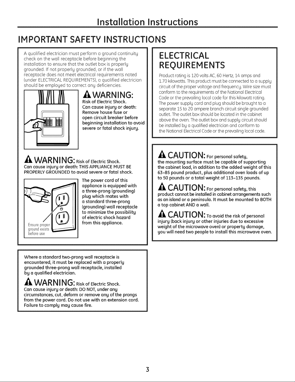
-A WARNI NG:RiskofElectricShock.
Can cause injury or death: THIS APPLIANCEMUSTBE
PROPERLYGROUNDEDto avoid severe or fatal shock.
The power cord of this
appliance is equipped with
a three-prong (grounding}
plug which mates with
a standard three-prong
(grounding) wall receptacle
to minimize the possibilitg
of electric shock hazard
Ensureproper
groundexists
beforeuse
from this appliance.
ELECTRICAL
REQUIREMENTS
Product rating is120 voltsAC,60 Hertz, 14 amps end
1.70kilowatts.Thisproduct must beconnected to a supply
circuit of the proper voltage end frequency. Wiresize must
conform to the requirements of the National Electrical
Codeor the prevailing local codefor this kilowatt rating.
The power supply cord and plug should be brought to a
separate 15to 20ampere branch circuit single grounded
outlet.The outlet box should be located in the cabinet
abovethe oven.Theoutlet box and supply circuit should
be installed by a qualified electrician and conform to
the National ElectricalCodeor the prevailing localcode.
CAUTION: For personal safetg,
the mounting surface must be capable of supporting
the cabinet load, in addition to the added weight of this
63-85 pound product, plus additional oven loads of up
to 50 pounds or a total weight of 113-135 pounds.
CAUTION: Forpersonalsafety,this
product cannot be installed in cabinet arrangements such
asan island or a peninsula. It must be mounted to BOTH
a top cabinet AND a wall.
-A CAUTION:Toavoidtheriskofpersonal
injurg (back injurg or other injuries due to excessive
weight of the microwave oven)or property damage,
you will need two people to install this microwave oven.
Where a standard two-prong wall receptacle is
encountered, it must be replaced with a properly
grounded three-prong wall receptacle, installed
by a qualified electrician.
-& WARNING: RiskofElectricShock.
Can cause injurg or death: DO NOT,under ang
circumstances, cut, deform or remove ang of the prongs
from the power cord. Do not usewith an extension cord.
Failure to complg mag cause fire.
3
Page 4
Installation Instructions
HOOD EXHAUST
NOTE:Readthesenexttwo pagesonlgifgou plantoventgourexhausttothe
outside.Ifgou plantorecirculatetheairbackintotheroom,proceedto page6.
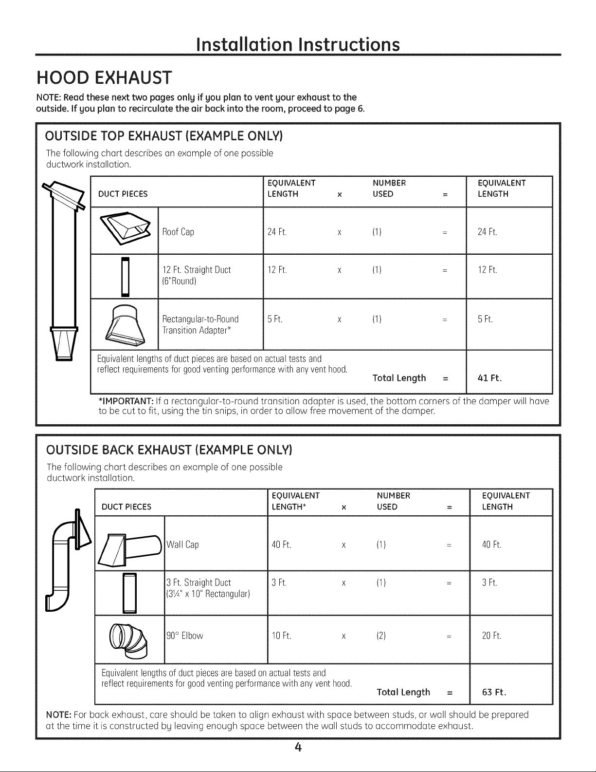
OUTSIDE TOP EXHAUST (EXAMPLE ONLY}
Thefollowing chart describes an example of one possible
ductwork installation.
EQUIVALENT NUMBER
DUCT PIECES
LENGTH x USED =
24Ft. x (1) =
12Ft.StraightDuct
RoofCap
12Ft. x (1) =
(6"Round)
5 Ft. x (1) = 5 Ft.
TransitionAdapter*
Rectangular-to-Round
Equivalentlengthsof ductpiecesare basedon actualtests and
reflectrequirementsfor goodventingperformancewith anyventhood.
*IMPORTANT:If a rectangular-to-round transition adapter is used, the bottom corners of the damper will have
to be cut to fit, using the tin snips, in order to allow free movement of the damper.
OUTSIDE BACK EXHAUST (EXAMPLE ONLY}
EQUIVALENT
LENGTH
24Ft.
12Ft.
Total Length = 41 Ft.
The following chart describes an example of one possible
ductwork installation.
DUCT PIECES
Wall Cap
3 Ft.StraightDuct
EQUIVALENT NUMBER
LENGTH* x USED
40 Ft. x (1)
3 Ft. x (1)
EQUIVALENT
LENGTH
40 Ft.
3 Ft.
31¼"x 10"Rectangular)
(2)
20 Ft.
_ 90°Elbow 10Ft. x
Equivalentlengthsof ductpiecesarebasedonactualtestsand
reflectrequirementsforgoodventingperformancewith anyvent hood.
Total Length =
63 Ft.
NOTE:For back exhaust, care should betaken to align exhaust with space between studs, or wall should be prepared
at the time it is constructed by leaving enough space between the wall studs to accommodate exhaust.
4
Page 5
Installation Instructions
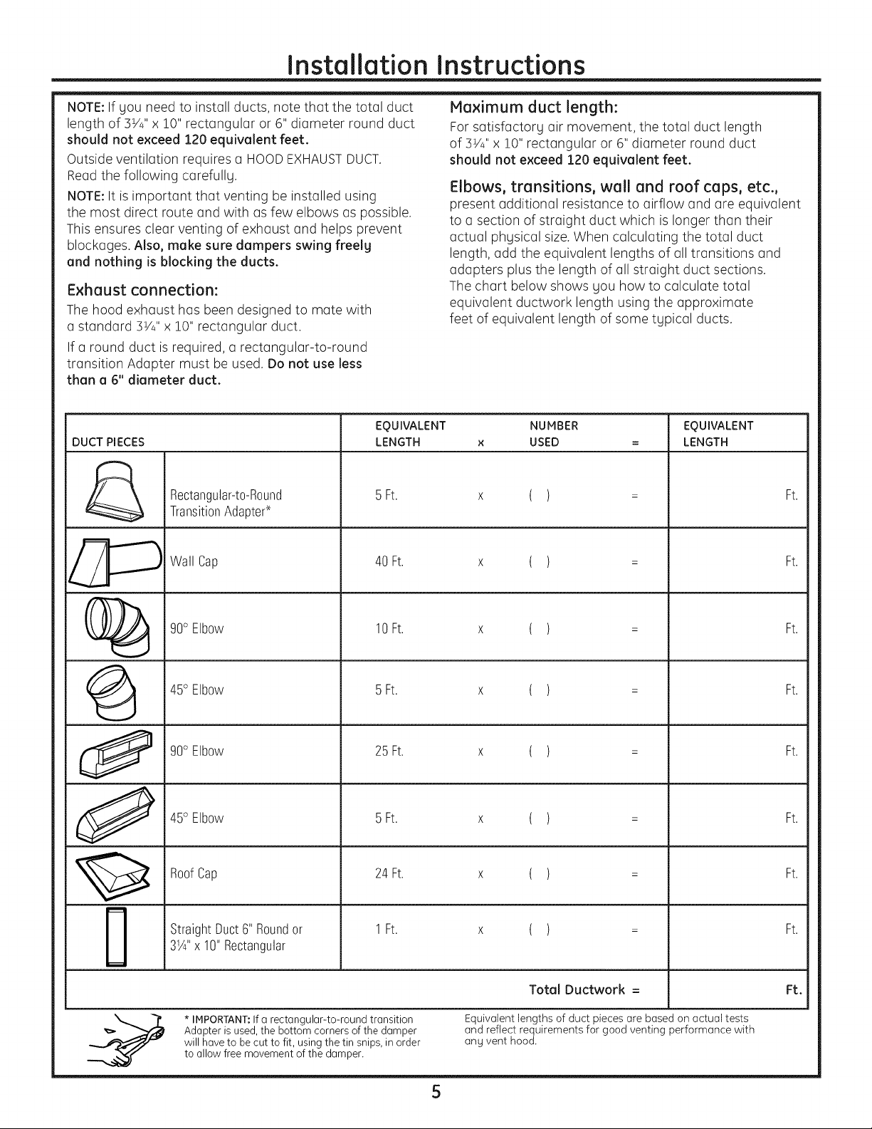
NOTE:If gou need to install ducts, note that the total duct
length of 5W' x 10" rectangular or 6" diameter round duct
should not e×ceed 120 equivalent feet.
Outside ventilation requires a HOODEXHAUSTDUCT.
Read the following carefully.
NOTE:It is important that venting be installed using
the most direct route and with as few elbows as possible.
This ensures clear venting of exhaust and helps prevent
blockages. Also, make sure dampers swing freelg
and nothing is blocking the ducts.
Exhaust connection:
The hood exhaust has been designed to mate with
a standard 5V_"x 10" rectangular duct.
If a round duct is required, a rectangular-to-round
transition Adapter must be used. Do not use less
than a 6" diameter duct.
EQUIVALENT
DUCT PIECES
Rectangular-t0-R0und
TransitionAdapter.×-
LENGTH
5 Ft.
Maximum duct length:
For satisfactory air movement, the total duct length
of 3V_"x 10" rectangular or 6" diameter round duct
should not exceed 120 equivalent feet.
Elbows, transitions, wall and roof caps, etc.,
present additional resistance to airflow and are equivalent
to a section of straight duct which is longer than their
actual phgsical size.When calculating the total duct
length, add the equivalent lengths of all transitions and
adapters plus the length of all straight duct sections.
The chart below shows gou how to calculate total
equivalent ductwork length using the approximate
feet of equivalent length of some tgpical ducts.
NUMBER
USED
( )
EQUIVALENT
LENGTH
Ft.
@
0
J
m
m
Wall Cap
90° Elbow
45° Elbow
90° Elbow
45° Elbow
RoofCap
StraightDuct6" Roundor
3_¼"x 10"Rectangular
40 Ft.
10Ft.
5 Ft.
25 Ft.
5 Ft.
24 Ft.
1Ft.
( )
( )
( )
( )
( )
( )
( )
Ft.
Ft.
Ft.
Ft.
Ft.
Ft.
Ft.
* IMPORTANT:Ifa rectangular-to-round transition
Adapter is used,the bottom corners of the damper
will have to be cut to fit, using the tin snips, in order
to allow free movement of the damper.
Total Ductwork = Ft.
Equivalent lengths of duct pieces are based on actual tests
and reflect requirements for good venting performance with
ang vent hood.
5
Page 6

Installation Instructions
DAMAGE- SHIPMENT/
INSTALLATION
• If the unit is damaged in shipment, return the unit
to the store in which it was bought for repair or
replacement.
• If the unit is damaged by the customer, repair or
replacement is the responsibility of the customer.
• If the unit is damaged by the installer (if other than
the customer), repair or replacement must be made
by arrangement between customer and installer.
PARTS INCLUDED
HARDWARE PACKET
PART QUANTITY
LagScrews(1A"x 2"} 4
(forwall studholes)
i _b_,_,_,,_ ToggleBolts(1/4"x 3") 4
(fordrywall holes)
SpringToggleHeads 4
(fortoggle bolts)
PARTS INCLUDED
ADDITIONAL PARTS
PART QUANTITY
i pperCabinet
÷ Template
RearWall
L •
..,0i Template
i (3pieces
mounting
plateonly)
installation
instructions
Exhaust
Adapter
Damper 1
Bolts 2
(forsecuringto
theuppercabinet)
TappingScrews(1A"x1A") 1black
(forattachingthe 2 bronze
damperductconnector)
PowerCordClampand 1
Dark-ColoredMounting
Screw(tohold
the powercord)
You will find the installation hardware contained
in a pocket with the unit. Check to make sure you
hove all these ports.
NOTE:Some extra ports ore included.
NOTE:You need to install at least two log screws
into a 2" x 4" stud and four anchor bolts into the wall.
Also, the mounting area must meet the 150 Ibs.weight
requirement.
PowerCord 1
____'_' ClampBushing
(forthecord
holeina metal
uppercabinet)
6
Page 7
Installation Instructions
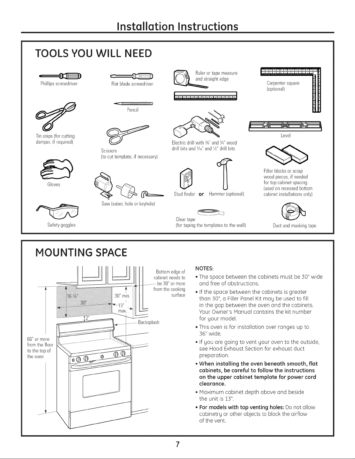
TOOLS YOU WILL NEED
Phillipsscrewdriver
Flatbladescrewdriver
Pencil
Ruleror tapemeasure
aightedge
Carpentersquare
(optional)
Tinsnips(forcutting
damper,if required)
Scissors
(to cut template, if necessary)
Gloves
Saw(saber,holeorkeyhole)
Safety goggles
MOUNTING SPACE
......._-......
66"ormore
fromthefloor
tothetopof
theoven
...... X
J
J
Level
Electricdrill with r½,,andr¼,,wood
drill bitsandr_?,and_½"drill bits
Fillerblocksorscrap
wood pieces,if needed
0
Studfinder or
Cleartape
(fortapingthetemplatestothewall)
Bottomedgeof
cabinetneedsto
.......... be30"or more
from thecooking
surface
J
Hammer(optional)
NOTES:
• The space between the cabinets must be ]0" wide
and free of obstructions.
• If the space between the cabinets is greater
than ]0", a Filler Panel Kit may be used to fill
in the gap between the oven and the cabinets.
Your Owner's Manual contains the kit number
for your model.
This oven is for installation over ranges up to
]6" wide.
If you are going to vent your oven to the outside,
see Hood Exhaust Section for exhaust duct
preparation.
• When installing the oven beneath smooth, flat
cabinets, be careful to follow the instructions
on the upper cabinet template for power cord
clearance.
• Maximum cabinet depth above and beside
the unit is 1]".
• For models with top venting holes: Do not allow
cabinetry or other objects to block the airflow
of the vent.
for top cabinetspacing
(usedon recessedbottom
cabinetinstallationsonly)
Duct and masking tape
Page 8
Installation Instructions
I-IPLACEMENT OF THE MOUNTING PLATE
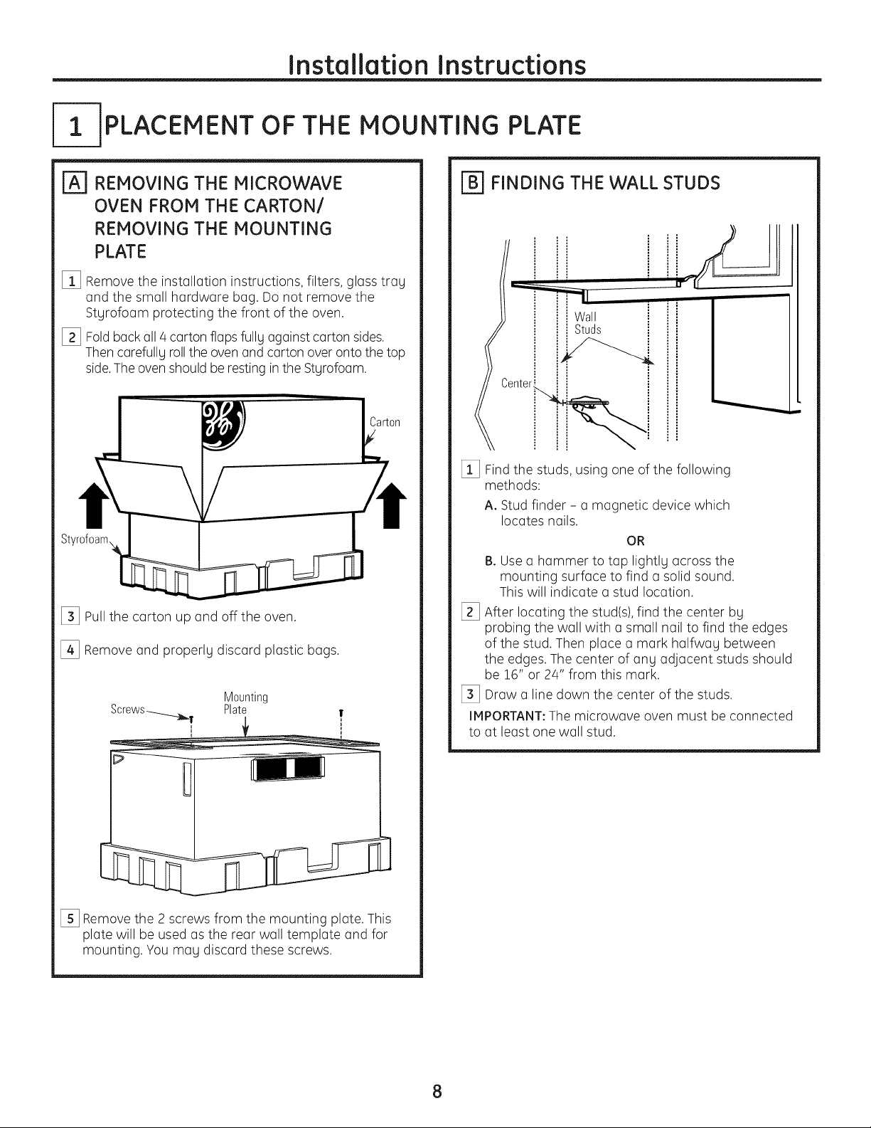
REMOVING THE MICROWAVE
OVEN FROM THE CARTON/
REMOVING THE MOUNTING
PLATE
[] Remove the installation instructions, filters, glass tray
and the small hardware bag. Do not remove the
Styrofoam protecting the front of the oven.
[_ Foldback all 4 carton flaps fully against carton sides.
Thencarefully rollthe oven and carton over onto the top
side.The oven should be resting in the Styrofoam.
[_ Pullthe carton up and off the oven.
[_ Remove and properly discard plastic bags.
Mounting
Plate
[_ FINDING THE WALL STUDS
I i
Wall
Studs
i
[] Find the studs, using one of the following
methods:
A. Stud finder - a magnetic device which
locates nails.
OR
B. Usea hammer to tap lightly across the
mounting surface to find a solid sound.
This will indicate a stud location.
[_ After locating the stud(s),find the center by
probing the wall with a small nail to find the edges
of the stud. Then place a mark halfway between
the edges. The center of any adjacent studs should
be !6" or 24" from this mark.
[_ Draw a line down the center of the studs.
IMPORTANT:The microwave oven must be connected
to at least one wall stud.
[_ Remove the 2 screws from the mounting plate. This
plate will be used as the rear wall template and for
mounting. You may discard these screws.
8
Page 9

Installation Instructions
[_] DETERMINING WALL PLATE LOCATION UNDER YOUR CABINET
Plate position - beneath flat bottom
cabinet
Mounting Plate Tabs
-Touching the Cabinet Bottom
k
At least 30", up to 36"
III
Plate position - beneath framed recessed
cabinet bottom
MountingPlateTabs
Touchingthe Back
Frame
II1
30" to Cooktop
Plate position - beneath recessed bottom
cabinet with front overhang
MountingPlatewith
TabsBelowCabinet
Bottom the Same
DistanceastheFront
OverhangDepth
...
i II
i II
Your cabinets mag hove decorQtive trim thQt interferes
with the microwave oven installQtion. Remove the
decorative trim to install the microwave oven properly
and to make it level.
THE MICROWAVEOVEN MUST BELEVEL.
Use a level to make sure the cabinet bottom is level.
If the cabinets hove a front overhQng onlg, with no
bQck or side frame, install the mounting plQtedown
the some distance as the front overhang depth.
This will keep the microwave oven level.
[] MeQsurethe inside depth of the front overhQng.
[_ DrQwa horizontal line on the back wall an equal
distance below the cabinet bottom as the insidedepth
of the front overhQng.
[_ Forthis type of installQtion with front overhQng only,
align the mounting tabs with this horizontal line,not
touching the cabinet bottom as described in Step D.
30" to Cooktop
9
Page 10

Installation Instructions
| ALIGNING THE WALL PLATE
HoleC Centerline
Notches
HoleB
Drawa Vertical
LineonWall
_-_ from Centerof
TopCabinet
0000000
0 0 0000000
!
AreaE
A CAUTION: Weor gloves
to avoid cutting fingers on sharp edges.
[]
Draw a vertical line on the wall at the center of the
]0" wide space.
%
Usethe mounting plate as the template for the rear
wall. Place the mounting plate on the wall, making
sure that the tabs are touching the bottom of the
cabinet or the level line drawn in Step C for cabinets
with front overhang. Line up the notch and centerline
on the bottom of the mounting plate to the centerline
on the wall.
%
While holding the mounting plate with one hand, draw
circles on the wall at holes A, B,Cand D (seeillustration
above/actual plate marked with arrows). Four holes
must be used for mounting.
NOTE:Holes Cand D are inside area E.If neither Cnor D
is in a stud, find a stud somewhere in area Eand draw
a fifth circleto line upwith the stud. It is important to use
at least one wood screw mounted firmlg in o stud to
support the weight of the microwave oven.
Set the mounting plate aside.
HoleD
A WARNING: RiskofElectricShock.Can
cause injury or death. Take care to not drill into electrical
wiring inside walls or cabinets.
[] Drillholes on the circles. If there is a stud, drill a YS' hole
for wood screws. Forholes that don't line up with a stud,
drill a %" holefor toggle bolts.
NOTE:DO NOTmount the plate at this time.
10
Page 11

Installation Instructions
INSTALLATION TYPESIChoose A, B or C)
This microwave oven is designed for adaptation
to the following three tgpes of ventilation:
A. Outside Top Exhaust (Vertical Duct}
B. Outside Back Exhaust (Horizontal Duct}
C. Recirculating (Non-Vented Ductless}
OUTSIDE TOP EXHAUST
{VERTICAL DUCT)
Adaptorin Placefor
I
OutsideTopExhaust
NOTE:This microwave oven isshipped assembled for Outside
Top Exhaust (except for non-vented models). Select the tgpe
of ventilation required for gour installation and proceed to
that section.
OUTSIDE BACK EXHAUST
{HORIZONTAL DUCT)
RECIRCULATING
{NON-VENTED DUCTLESS)
11
A Charcoal Filter Accessorg Kit
is required for the non-vented
exhaust. (Seegour Owner's
Manual for the kit number.)
Page 12

Installation Instructions
J-AIOUTSIDE TOP EXHAUST {Vertical Duct)
INSTALLATION OVERVIEW
A1. Attach Hounting Plate to Wall
A2. Prepare Top Cabinet
A3. Attach Exhaust Damper
A4. Hount Hicrowave Oven
IAll ATTACH THE MOUNTING PLATE
TO TH E WALL
II
Attach the plate to the wall using toggle bolts.
At least one wood screw must be used to attach
the plate to a wall stud.
[] Remove the toggle wings from the bolts.
[] Insert the bolts into the mounting plate through
the holes designated to go into drywall and reattach
the toggle wings to s/4"onto each bolt.
To use toggle bolts:
Spacingfor Toggles
MoreThanWall
-_l_,-_j_Thickness
ToggleWings
Mounting
Plate
,,I,
BoltEnd
[_ Place the mounting plate against the wall and insert
the toggle wings into the holes in the wall to mount
the plate.
NOTE:Before tightening toggle bolts and wood screw,
make sure the tabs onthe mounting plate touch
the bottom of the cabinet when pushed flush against
the wall and that the plate is properly centered under
the cabinet.
-A CAUTION: Be careful to avoid pinching
fingers between the back of the mounting plate and
the wall.
[_ Tighten all bolts. Pull the plate away from the wall
to help tighten the bolts.
12
Page 13

Installation Instructions
USE TOP CABINET TEMPLATE FOR
PREPARATION OF TOP CABINET
You need to drill holes for the top support screws, a hole
large enough for the power cord to fit through, and
a cutout large enough for the exhaust adaptor.
• Readthe instructions on the TOPCABINETTEMPLATE.
Tape it underneath the top cabinet.
Drillthe holes, following the instructions on the TOP
CABINETTEMPLATE.
-A CAUTION: Wear safet u goggles when
drilling holes in the cabinet bottom.
ATTACH EXHAUST DAMPER
Blowerplate
mounting screw
_e _ (3 screws)
| MOUNT THE MICROWAVE OVEN
CAUTIO N:TO avoid the risk of personal
injurg (back injurg or other injuries due to excessive
weight of the microwave oven} or propertg damage,
gou will need two people to install this microwave
oven.
IMPORTANT:Do not grip or use handle during
installation.
-4,WARN! NG:RiskofElectricShock.Can
cause injurg or death: If installing unit with metal
countertops, cover the edge of the power supplg
cord hole with the power supplg cord bushing.
IMPORTANT:If filler blocks are not used, case damage
may occur from overtightening screws.
NOTE:When mounting
the microwave oven,
thread power cord through
hole in bottom of top
cabinet. Keep it tight
throughout Steps 1-3. Do
not pinch cord or lift oven
bg pulling cord.
[] Lift microwave oven,
tilt it forward, and hook
slots at back bottom
edge onto four lower
tabs of mounting plate.
Blowerunit_ower plate
____Z 'BIowerunit
Placethe microwave oven in its upright position, with
the top of the unit facing up.
This microwave oven is shipped assembled for top
exhaust.
• Attach the exhaust adapter to the blower plate bg
sliding it into the guide.
You will need to make adjustments to ensure proper
alignment with gour house exhaust duct after the
microwave oven is installed.
mounting screw
(2screws)
[_ Rotate front of oven up
against cabinet bottom.
[_ Insert a self-aligning screw through top-center
cabinet hole.Temporarilg secure the oven bg
turning the screw at least two full turns after
the threads have engaged. (It will be completely
tightened later.)
13
Page 14

Installation Instructions
MOUNT THE MICROWAVE OVEN
{cont.)
Dan_er
I
Use the power supplg cord clomp to bundle the
power supplg cord. Instoll the power supplg cord
clomp, using o screw os shown, to the inside of
the cobinet.
CabinetFront
CabinetBottomShelf
FillerBlock
to Depth
ofCabinet
T quivalent
Recess
Self-AligningScrew
MicrowaveOvenTop
[_] Attoch the microwove oven to the top cobinet.
[_ Insert 2 self-oligning screws
through outer top cobinet
holes. Turn two full turns
on eoch screw.
[_] Tighten the two screws to the top of the
microwove oven. (While tightening screws, hold
the microwove oven in ploce ogoinst the woll
ond the top cobinet.)
I_ liL--
[] Instoll greose filter. Seethe Owner's Monuol
pocked with the microwove oven.
14
Page 15

Installation Instructions
[- OUTSIDE BACK EXHAUST {Horizontal Duct)
INSTALLATION OVERVIEW
BI. Prepare Rear Wall
B2. Attach Mounting Plateto Wall
B3. Prepare Top Cabinet
B4. Adjust Blower
BS. Mount the Microwave Oven
PREPARE THE REAR WALL
FOR OUTSIDE BACK EXHAUST
You need to cut an opening in the rear wall for outside
exhaust.
• Readthe instructions on the REARWALLTEMPLATE.
• Tape it to the rear wall, lining up with the holes
previouslg drilled for holes A and B in the wall plate.
• Cut the opening, following the instructions of the
REARWALLTEMPLATE.
15
Page 16

Installation Instructions
[-_ ATTACH THE MOUNTING PLATE
TO THE WALL
!
Attach the plate to the wall using toggle bolts.
At least one wood screw must be used to attach
the plate to a wall stud.
[] Removethe toggle wings from the bolts.
I_ Insert the bolts into the mounting plate through
the holes designated to go into drywall and reattach
the toggle wings to 3/a"onto each bolt.
To use toggle bolts:
SpacingforTogglesMore
--I-_--!-,_- ThanWallThickness
M .. IToggleWings
oummg II1'._1i I ToggleII 1'..1
P ate lll:l Bolt II I::K
USE TOP CABINET TEMPLATE FOR
PREPARATION OF TOP CABINET
You need to drill holes for the top support screws and
a hole large enough for the power cord to fit through.
• Readthe instructions on the TOPCABINETTEMPLATE.
• Tape it underneath the top cabinet.
• Drill the holes, following the instructions on the TOP
CABINETTEMPLATE.
-A CAUTION: Wear safetg goggles when
drilling holes in the cabinet bottom.
[--_ ADAPT MICROWAVE OVEN
BLOWER FOR OUTSIDE BACK
EXHAUST
III ':t_--Wall II lql I
BoltEnd
[_ Placethe mounting plate against the wall and insert
the toggle wings into the holes in the wall to mount
the plate.
NOTE:Before tightening toggle bolts and wood screw,
make sure the tabs on the mounting plate touch
the bottom of the cabinet when pushed flush against
the wall and that the plate is properlg centered under
the cabinet.
-A CAUTION: Be careful to avoid pinching
fingers between the back of the mounting plate and
the wall.
[_ Tighten all bolts. Pullthe plate awag from the wall
to help tighten the bolts.
[] Remove and save 3 blower plate mounting screws
and 2 blower unit mounting screws.
Blowerplate
mountingscrew
.__ (3screws)
Blowerunit
_ Blowerplate
__ Backplate
-_d_---------- mountingscrew
Use side cutters or tin snips to cut and remove
knockouts from back plate. Discard the knockouts.
Be careful not to distort the plate.
3lowerunit
(2screws)
16
Page 17

Installation Instructions
J--_ ADAPT MICROWAVE OVEN
BLOWER FOR OUTSIDE BACK
EXHAUST (cont.)
[_ Carefully pull out the blower unit. The wires
will extend far enough to allow you to adjust
the blower unit.
EndA
[_ Rotate the unit so that the exhaust ports face
the rear of the cabinet. When you insert the blower
unit, the blower wire must be as shown.
Blowerunit
EndB
[_ Reattach the blower plate to the cabinet so
the exhaust ports and blower plate opening
are aligned. Attach with 2 blower unit mounting
screws and then ] blower plate mounting screws.
Blowerplate
Blowerunit
Blowerunitexhaustports (2screws)
[_ Attach the exhaust adapter to the rear of the
oven by sliding it into the guides at the top
center of the back of the oven.
Adapter
.__ (3screws)
........ ............. wer plate"!"" i
__'Blowe[ unit
_ _ - mounting screw
mounting screw
Backof
MicrowaveOven
Exhaustports
[_ Place the blower unit back into the cabinet.
Check that the exhaust ports face toward
the rear of the cabinet.
WARNING: Riskofelectricshock
can cause injury or death. Do not pull or stretch
the blower unit wiring. Make sure the wires
are not pinched.
NOTE:The blower unit exhaust openings should
match exhaust openings on rear of microwave oven.
Guide
Guide
Push in securely until it is in the lower locking
tabs. Take care to ensure that the damper hinge
is installed so that it is at the top and that the
damper swings freely.
"_ LockingTabs
17
Page 18

Installation Instructions
MOUNT THE MICROWAVE OVEN
-&CAUTIO N: To°voidtheriskofpersonal
injurg (back injurg or other injuries due to excessive
weight of the microwave oven) or propertg damage,
gou will need two people to install this microwave
oven.
IMPORTANT:Do not grip or use handle during
installation.
-&WARNI NG:Risk of Electric Shock.
Can cause injurg or death: If installing unit with
metal countertops, cover the edge of the power
supplg cord hole with the power supplg cord
bushing.
IMPORTANT:If filler blocks are not used, case damage
may occur from overtightening screws.
Dan_er
I
Usethe power supplg cord clamp to bundle the
power supplg cord. Install the power supplg cord
clamp, using a screw as shown, to the inside of
the cabinet.
CabinetFront
CabinetBottomShelf
FillerBlock
Equivalent
to Depth
ofCabinet
Recess
Self-AligningScrew
MicrowaveOvenTop
[_] Attach the microwave oven to the top cabinet.
NOTE:When mounting the
microwave oven, thread
power cord through hole
in bottom of top cabinet.
Keep it tight throughout
Steps 1-3. Do not pinch
cord or lift oven bg pulling
cord.
_] Rotate front of oven up
against cabinet bottom.
[_] Insert a self-aligning screw through top-center
cabinet hole.Temporarily secure the oven by
turning the screw at least two full turns after
the threads hove engaged. (It will be completely
tightened later.)
[] Lift microwave oven,
tilt it forward, and hook
slots at back bottom
edge onto four lower
tabs of mounting plate.
[_ Insert 2 self-aligning screws
through outer top cabinet
holes. Turn two full turns
on each screw.
[_] Tighten the two screws to the top of the
microwave oven. (While tightening screws, hold
the microwave oven in place against the wall
and the top cabinet.)
I/liL_
[_ Install grease filter. Seethe Owner's Manual
pocked with the microwave oven.
18
Page 19

Installation Instructions
IC-1RECIRCULATING (Non-Vented Ductless)
INSTALLATION OVERVIEW
C1. Attach Mounting Plate to Wall
C2. Prepare Top Cabinet
C3. Adjust Blower
C4. Mount the Microwave Oven
C5. Install Charcoal Filter
ATTACH THE MOUNTING PLATE
TO TH E WALL
|
i
[_ Place the mounting plate against the wall and insert
the toggle wings into the holes in the wall to mount
the plate.
NOTE:Before tightening toggle bolts and wood screw,
make sure the tabs onthe mounting plate touch
the bottom of the cabinet when pushed flush against
the wall and that the plate is properly centered under
the cabinet.
.4,CAUTION: Be careful to avoid pinching
fingers between the back of the mounting plate and
the wall.
\
Attach the plate to the wall using toggle bolts.
At least one wood screw must be used to attach
the plate to a wall stud.
[] Removethe toggle wings from the bolts.
[_ Insert the bolts into the mounting plate through
the holes designated to go into drywall and
reattach the toggle wings to s/4"onto each bolt.
To use toggle bolts:
Spacingfor Toggles
MoreThanWall
-,-J._,-i.,_Th ickness
Mounting
Plate
ToggleWings
BoltEnd
[_ Tighten all bolts. Pull the plate away from the wall
to help tighten the bolts.
USE TOP CABINET TEMPLATE FOR
PREPARATION OF TOP CABINET
You need to drill holes for the top support screws and
a hole large enough for the power cord to fit through.
• Readthe instructions on the TOPCABINETTEMPLATE.
• Tape it underneath the top cabinet.
• Drill the holes,following the instructions on the TOP
CABINETTEMPLATE.
CAUTION: Wearsafetygogglesw,en
drilling holes in the cabinet bottom.
19
Page 20

Installation Instructions
ADAPT MICROWAVE OVEN
BLOWER FOR RECIRCULATION
[] Remove and save ] blower plate screws
and 2 blower unit mounting screws.
.-_ mountingscrew
..........! : (3 screws)
Blowerunit
[_ Carefullg pull out the blower unit. The wires
will extend far enough to allow gou to adjust the
blower unit.
[_ Rollthe blower unit 90° so that fan blade openings
are facing toward the front of the microwave oven.
_--_Blower plate
_B Bacl<plate
J '",_ raountlngscrew
Blowerplate
Iowe[ unit
(2 screws)
NOTE:Make sure wires remain routed in the grooves
of the motor frame.
[_ Placethe blower unit back into the opening.
WARNi NG:Riskofelectricshockcan
cause injury or death. Do not pull or stretch the
blower unit wiring. Make sure the wires are not
pinched.
[_ Reattach the blower plate to the microwave oven.
Attach with the ] blower plate mounting screws
and then the 2 blower unit mounting screws.
Blower plate
_"].............i mounting screw
..........!_ (3 screws)
Blower unit
Blower plate
Roll 4_--'_
_ Bacl<plate
_LJ j ' Blowerunit
J_ --':__ mountingscrew
(2 screws)
2O
Page 21

Installation Instructions
r=_ MOUNT THE MICROWAVE OVEN
-_CAUTION: Toovoidtheriskofpersonal
injury (back injury or other injuries due to excessive
weight of the microwave oven) or property damage,
you will need two people to install this microwave
oven.
IMPORTANT:Do not grip or use hondle during instollotion.
-_WARNING: RiskofElectricShock.
Can cause injury or death: If installing unit with metal
countertops, cover the edge of the power supply cord
hole with the power supply cord bushing.
IMPORTANT:If filler blocks ore not used, case domege
may occur from overtightening screws.
NOTE:When mounting the
microwave oven, threod
power cord through hole
in bottom of top cabinet.
Keep it tight throughout
Steps 1-3. Do not pinch
cord or lift oven by pulling
cord.
[] Lift microwove oven,
tilt it forword, ond hook
slots ot bock bottom
edge onto four lower
tobs of mounting plote.
% Usethe power supply cord clomp to bundle the
power supply cord. Instoll the power supply cord
clomp, using o screw os shown, to the inside of
the cobinet.
CabinetFront
-X CabinetBottomShelf
PF1_ / FillerBlock
!.II : -,_lr_ Equivalentto Depth
/!!ll TofcabinetRe ess
J I1,\_ ,11I_III!//1!11 _____
Microwave Oven Top
[_3 Attoch the microwove oven to the top cobinet.
[_3 Insert 2 self-oligning screws through outer top
cobinet holes.Turn two full turns on eoch screw.
[_3 Rotote front of oven up
ogoinst cobinet bottom.
[_]lnsert o self-oligning screw through top center
cobinet hole.Tempororily secure the oven by
turning the screw ot leost two full turns offer
the threods hove engoged. (It will be completely
tightened Ioter.)
i
[] Tighten the two screws to the top of the microwove
oven. (While tightening screws, hold the microwove
oven in ploce ogoinst the woll ond the top cobinet.)
I/ IL_
[_3 Instoll greose filter. Seethe Owner's Monuol pocked
with the microwove oven.
21
Page 22

Installation Instructions
ICSl INSTALLING THE CHARCOAL
FILTER
[_ Remove 2 screws on the top front of the grille using
a Phillips screwdriver.
[_ Open the door.
[_ Remove the grille, pulling it straight off.
Charcoal
Filter
[_ Install the charcoal filter. When properlu installed,
the wire mesh of the filter should be visible from
the front.
[_ Replace the grille and the screws.
[_ Close the door.
Insertmesh-sideup
22
Page 23

Installation Instructions
BEFORE YOU USE YOUR MICROWAVE OVEN
Make sure the microwave oven has been
installed according to instructions.
]_l Remove all packing material from the
microwave oven.
r61 Read the Owner's Manual.
KEEPINSTALLATION INSTRUCTIONS FORTHE
LOCAL INSPECTOR'S USE.
_] Install turntable and ring in cavitg.
i
_ Replace house fuse or turn breaker back on.
r_ lUgpower cord into a dedicated 15- to 20-amp
electrical outlet.
r
J
i"
/ Q
beforeuse ""
]
23
Page 24

Printed in China
 Loading...