

Page 1
I stallati
Above the
I str
cti
BEFORE YOU BEGIN
Read these instructions completely and carefully.
•IMPORTANT - Sovethese
instructionsforlocolinspector'suse.
•IMPORTANT-Observeoll
governingcodesondordinonces.
• Note to Installer- Be sureto leovethese
instructionswiththeConsumer.
Cooktop Ove
Model JVM2052
Note to Consumer - Keepthese instructions
for future reference.
Skill level - Instollotion of this opplionce requires bosic
mechonicol ond electricol skills.
o
Proper instollotion is the responsibility of the instoller.
o
Product foilure due to improper instollotion is not
covered under the Worronty.
HFL57007101
I 49-40587 1
09-08 JR
/
/
READ CAREFULLY.
KEEP THESE INSTRUCTIONS.
Page 2
Installation Instructions
CONTENTS
General information
Important Safety Instructions ...................................... 3
Electrical Requirements .................................................. 3
Hood Exhaust ................................................................ 4-5
Damage-Shipment/Installation .................................. 6
Parts Included .................................................................. 6
Tools You Will Need .......................................................... 7
Mounting Space ................................................................ 7
Step-by-step installation guide
Prepare the Electrical Connections .............................. 8
Prepare the Venting System .......................................... 9
Prepare the Venting ................................................ 10-11
Before You Start .................................................. 10
Remove the Mounting Plate .............................. 10
Installation Tgpes .......................................... 10-11
Room-Vented (recirculating)
Installation .................................................. 10
Wall-Vented Installation ...................... 10-11
Roof-Vented Installation ............................ 11
Prepare the Wall & Upper Cabinet ........................ 12-13
Measure and Tack/Tape up the Templates .... 12
Drill the Holes in the Wall and
Upper Cabinet ................................................ 12-13
Install the Mounting Plate ...................................... 13-14
Wall Stud ........................................................ 13-14
Wall-Vented ........................................................ 14
Attach the Oven to the Wall ........................................ 15
2
Page 3
Installation Instructions
IMPORTANT SAFETY INSTRUCTIONS
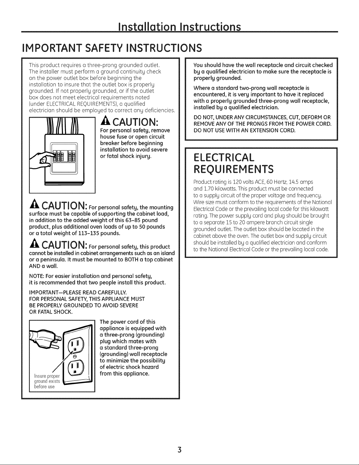
This product requires a three-prong grounded outlet.
The installer must perform a ground continuitg check
on the power outlet box before beginning the
installation to insure that the outlet box is properlg
grounded. If not properlg grounded, or if the outlet
box does not meet electrical requirements noted
(under ELECTRICALREQUIREMENTS),a qualified
electrician should be emploged to correct ang deficiencies.
I}}/I -&CAUTION:
i For personal safetg, remove
house fuse or open circuit
breaker before beginning
installation to avoid severe
or fatal shock injurg.
-& CAUTION: For personal safetg, the mounting
surface must be capable of supporting the cabinet load,
in addition to the added weight of this 63-85 pound
product, plus additional oven loads of up to 50 pounds
or a total weight of 113-135 pounds.
-A CAUTION: Forpersonalsafetg,thisproduct
cannot be installed in cabinet arrangements suchasan island
or a peninsula. It must be mounted to BOTHa top cabinet
AND a wall.
You shouldhave the wall receptacle and circuit checked
bg a qualified electrician to make sure the receptacle is
properlg grounded.
Where a standard two-prong wall receptacle is
encountered, it isverg important to have it replaced
with a properlg grounded three-prong wall receptacle,
installed bg a qualified electrician.
DO NOT, UNDER ANY CIRCUMSTANCES, CUT, DEFORM OR
REMOVE ANY OF THE PRONGS FROM THE POWER CORD.
DO NOT USE WITH AN EXTENSION CORD.
ELECTRICAL
REQUIREMENTS
Product rating is120 voltsACE,60 Hertz,14.5 amps
and !.70 kilowatts.This product must be connected
to a supplg circuit of the proper voltage and frequencg.
Wire sizemust conform to the requirements ofthe National
ElectricalCode or the prevailing local code for this kilowatt
rating.The power supplg cord and plug should be brought
to a separate !5 to 20 ampere branch circuit single
grounded outlet. The outlet box should be located in the
cabinet above the oven.Theoutlet box and supplg circuit
should be installed bg a qualified electrician and conform
to the National Electrical Codeor the prevailing local code.
NOTE: For easier installation and personal safetg,
it is recommended that two people install this product.
IMPORTANT--PLEASE READ CAREFULLY.
FOR PERSONAL SAFETY,THIS APPLIANCE MUST
BE PROPERLY GROUNDED TO AVOID SEVERE
OR FATAL SHOCK.
The power cord of this
appliance is equipped with
a three-prong (grounding)
plug which mates with
a standard three-prong
(grounding} wall receptacle
to minimize the possibilitg
ofelectric shockhazard
Insureproper
groundexists
beforeuse
from this appliance.
3
Page 4
Installation Instructions
HOOD EXHAUST
NOTE:Readthesenexttwo pagesonlgifgou plantoventgourexhausttothe
outside.Ifgou plantorecirculatetheairbackintotheroom,proceedto page6.
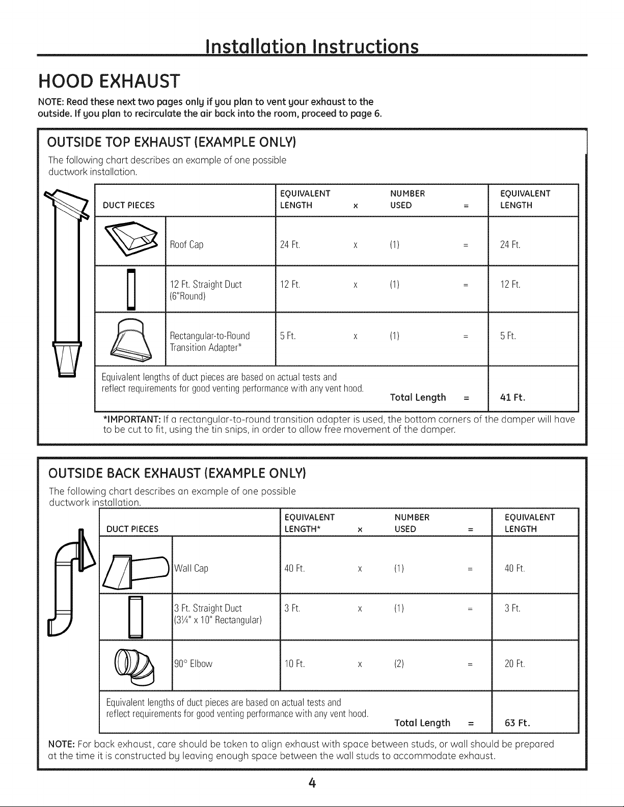
OUTSIDE TOP EXHAUST (EXAMPLE ONLY}
Thefollowing chart describes an example of one possible
ductwork installation.
EQUIVALENT NUMBER
DUCT PIECES
LENGTH x USED =
24Ft. x (1) =
12Ft.StraightDuct
RoofCap
12Ft. x (1) =
(6"Round)
5 Ft. x (1) =
TransitionAdapter*
Rectangular-to-Round
Equivalentlengthsof ductpiecesarebasedon actualtests and
reflectrequirementsfor goodventingperformancewith anyventhood.
*IMPORTANT:If a rectangular-to-round transition adapter is used, the bottom corners of the damper will have
to be cut to fit, using the tin snips, in order to allow free movement of the damper.
OUTSIDE BACK EXHAUST (EXAMPLE ONLY}
EQUIVALENT
LENGTH
24Ft.
12Ft.
5 Ft.
Total Length = 41 Ft.
The following chart describes an example ofone possible
ductwork installation.
DUCT PIECES
Wall Cap
3 Ft.StraightDuct
EQUIVALENT NUMBER
LENGTH* x USED
40 Ft. x (1)
3 Ft. x (1)
EQUIVALENT
LENGTH
40 Ft.
3 Ft.
31¼"x 10"Rectangular)
(2)
20 Ft.
(_ 90° Elbow 10Ft. x
Equivalentlengthsof ductpiecesarebasedonactualtestsand
reflectrequirementsforgoodventingperformancewith anyvent hood.
Total Length =
63 Ft.
NOTE:For back exhaust, care should be taken to align exhaust with space between studs, or wall should be prepared
at the time it is constructed by leaving enough space between the wall studs to accommodate exhaust.
4
Page 5
Installation Instructions
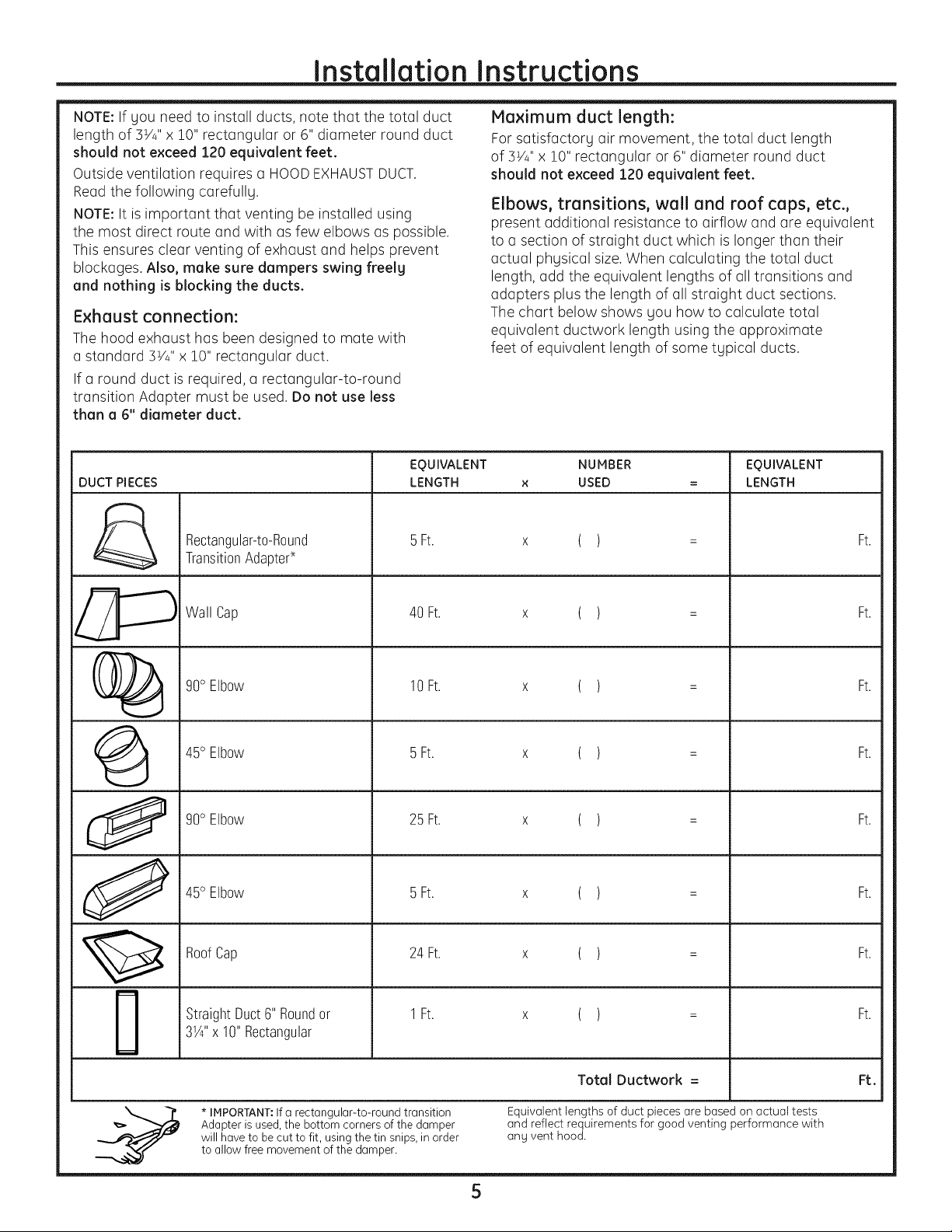
NOTE:If gou need to install ducts, note that the total duct
length of 5W' x 10" rectangular or 6" diameter round duct
should not exceed 120 equivalent feet.
Outside ventilation requires a HOODEXHAUSTDUCT.
Read the following carefully.
NOTE:It is important that venting be installed using
the most direct route and with as few elbows as possible.
This ensures clear venting of exhaust and helps prevent
blockages. Also, make sure dampers swing freelg
and nothing is blocking the ducts.
Exhaust connection:
The hood exhaust has been designed to mate with
a standard 5V/' x 10" rectangular duct.
If a round duct is required, a rectangular-to-round
transition Adapter must be used.Do not use less
than a 6" diameter duct.
EQUIVALENT
DUCT PIECES
Rectangular-to-Round
TransitionAdapter*
LENGTH
5Ft.
Maximum duct length:
For satisfactory air movement, the total duct length
of 3V/' x 10" rectangular or 6" diameter round duct
should not exceed 120 equivalent feet.
Elbows, transitions, wall and roof caps, etc.,
present additional resistance to airflow and are equivalent
to a section of straight duct which is longer than their
actual phgsical size.When calculating the total duct
length, add the equivalent lengths of all transitions and
adapters plus the length of all straight duct sections.
The chart below shows gou how to calculate total
equivalent ductwork length using the approximate
feet of equivalent length of some tgpical ducts.
NUMBER
USED
( )
EQUIVALENT
LENGTH
Ft.
@
0
J
m
m
Wall Cap
90° Elbow
45° Elbow
90° Elbow
45° Elbow
RoofCap
StraightDuct6" Roundor
3¼"x 10"Rectangular
40 Ft.
10 Ft.
5 Ft.
25 Ft.
5 Ft.
24 Ft.
1Ft.
( )
( )
( )
( )
( )
( )
( )
Ft.
Ft.
Ft.
Ft.
Ft.
Ft.
Ft.
* IMPORTANT:Ifa rectangular-to-round transition
Adapter is used,the bottom corners of the damper
will have to be cut to fit, using the tin snips, in order
to allow free movement of the damper.
Total Ductwork = Ft.
Equivalent lengths of duct pieces are based on actual tests
and reflect requirements for good venting performance with
ang vent hood.
5
Page 6

Installation Instructions
DAMAGE- SHIPMENT/
INSTALLATION
• If the unit is damaged in shipment, return
the unit to the store in which it was bought for
repair or replacement.
• If the unit is damaged by the customer, repair
or replacement isthe responsibility of the customer.
• If the unit is damaged bg the installer (ifother
than the customer), repair or replacement must
be made by arrangement between customer
and installer.
PARTS INCLUDED
HARDWARE PACKET
LPART _ QUANTITY
LagScrews(Y4"x 2") 4
(forwall studholes)
_!_ . ToggleBolts(1/4"x3") 4
(fordrywall holes)
PARTS INCLUDED
ADDITIONAL PARTS
PART
i pperCabinet
+ Template
L ....... _.........
INSTALLATION I
INSTRUCTIONs
.,o i Template
i (3 pieces
RearWall
mounting
plateonly)
installation
instructions
Exhaust
Adapter
SpringToggleHeads 4
(fortoggle bolts)
Bolts 2
!bww,_,_,_ (forsecuringto
theuppercabinet)
_:) TappingScrews(½"x1A") 1black
You will find the installation hardware contained
in a packet with the unit. Check to make sure you
have all these parts.
NOTE:Some extra parts are included.
NOTE:You need to install at least two lag screws
into a 2" x 4" stud and four anchor bolts into the wall.
Also, the mounting area must meet the 150 Ibs.weight
requirement.
(forattachingthe 2 bronze
damperductconnector)
PowerCordClampand
Dark-ColoredMounting
Screw(tohold
the powercord)
1
Damper 1
PowerCord
ClampBushing
(forthecord
holeina metal
uppercabinet)
6
Page 7

Installation Instructions
TOOLS YOU WILL NEED
Phillipsscrewdriver
Tinsnips(forcutting
damper,if required)
Gloves
Flatbladescrewdriver
Pencil
Scissors
(to cut template, if necessary)
@===_
Saw(saber,holeorkeyhole)
Ruleror tapemeasure
aightedge
Electricdrill with 3A"and 3¼,,wood
drill bitsand34¢and _½"drill bits
8
Studfinder or
Hammer(optional)
Carpentersquare
(optional)
Plumbline
4P"
Caulking gun
Safety goggles
MOUNTING SPACE
II i Ill III I UJJ Bottomedgeof
NOTE:Maximumcabinetdepthis13". _ cabinetneedsto
-- E---" fromthecooking
Bacl<splash
66"or more
fromthe floor
tothe top of
theoven
be30"ormore
surface
Clear tape
(for taping the templates to the wall)
NOTES:
• The space between the cabinets must be ]0" wide
and free of obstructions.
• If the space between the cabinets is greater
than ]0", a Filler Panel Kit mag be used to fill
in the gap between the oven and the cabinets.
Your Owner's Manual contains the kit number
for gour model.
• This oven isfor installation over ranges up to
36" wide.
• If gou are going to vent gour oven to the outside,
see Hood Exhaust Section for exhaust duct
preparation.
• When installing the oven beneath smooth, flat
cabinets, be careful to follow the instructions
on the upper cabinet template for power cord
clearance.
• Maximum cabinet depth above and beside
the unit is !]".
• For models with top venting holes: Do not allow
cabinetrg or other objects to block the airflow
of the vent.
Duct and masking tape
Page 8

Installation Instructions
r-_ PREPARE THE ELECTRICAL
CONNECTIONS
-4,WARNING: Avoidelectricalshock!
This appliance must be grounded!
[] Locate the grounded electric outlet for this oven
in the cabinet above the oven, as shown at right.
NOTE:The outlet should be on a circuit dedicated
to the microwave oven (120V,60 Hz.,AC only) with
a !5 or 20A fused electrical supply.
IMPORTANT:If you do not have the proper wall
outlet, you MUSThave one installed by a qualified
electrician.
-4,WARNING: Improper grounding could
result in electric shock or other personal injury.
DO NOT, UNDER ANY CIRCUMSTANCES, REMOVE
THE POWER SUPPLYCORD GROUNDING PRONG!
• This appliance MUSTbe grounded!
I_ Youwill cut the power-supply-cord hole (shown
below) later when you prepare the wall and upper
cabinet in Step 4.
NOTE:Do not use an extension cord. Keepthe power
cord dry and do not pinch or crush it.
Groundedoutlet
cabinet
Upper t
J
Power-supply-cordhole
ii!!!iJi
(insidecabinet)
8
Page 9

Installation Instructions
PREPARE THE VENTING SYSTEM
NOTE:The ductwork you need for outside ventilation
isnot included with your oven. The standard ductwork
fittings and length are shown on pages 4 and 5.
-&WARNING: This oven must be properly
vented.
You may vent your oven in one of three ways. Do NOT
vent into a wall cavity, an attic or an unused area.
Roof Venting--If your oven is located on an outside
wall near the roof, as shown below (3 1/4" x 10" duct
or 6" round duct).
Roofcap
all
--di,
3 1/4"to round
ducttransition
Roofventing
/
3 1/4"x 10"duct
Through-the-roof
cap
Wall Venting-If your oven is located on an outside
wall of your house, as shown below (3 1/4" x 10" duct
or 6" round duct.)
Roofcap
Cabinet !i!!iil_ _Wi_iiii ii_. J_,
Oven
Wallventing 3 /4"to round
3 1/4" x 10" Wall cap
Through-the-wall
Room Venting--If your oven is located on an inside
wall of your house, as shown below.
Cabinet
ducttransition
Ove:
NOTE:If you choose the rear exhaust method
(roof- or wall-venting), be sure there is enough
clearance within the wall for the exhaust duct.
cap
REMEMBERAS YOU INSTALLTHEVENTING: Keep
the length of the ductwork and the number of elbows
to a minimum to ventilate your oven efficiently. See
examples on page 5. Keep the size of the ductwork
the same. Do not install two elbows together. Use duct
tape to seal all joints in the duct system. Usecaulking
to seal the exterior wall or roof opening around
the cap.
9
Page 10

Installation Instructions
[_ PREPARE THE VENTING
AWARNING:
• To avoid the risk of property damage, unplug the
microwave oven or disconnect power at the source
by removing the fuse or throwing the circuit breaker.
• To avoid the risk of personal injury, wear protective
gloves when handling the mounting plate.
• DO NOTPULLORSTRETCHTHEBLOWERWIRING!
Pulling and stretching the blower wiring could result
in electrical shock.
NOTE:Your microwave oven is shipped with the blower
assembled for room venting. If you want wall-vented
or roof-vented installation, you must change the blower,
as detailed below.
F_ BEFORE YOU START
[] Remove any shipping materials and parts from
inside the microwave oven.
[]
Cover the counter top or cooktop with a thick,
protective covering to protect it from damage
and dirt.
Athick,protective
%
This plate will be used as the rear mounting plate.
(It will be used to locate and mark the mounting
holes on the rear wall.
%
Locate the exhaust adapter, grease filters and
hardware packet.
%
At this point, remove any adhesive tape (if there is
any), on the exhaust adapter, the grease filters and
the power supply cord.
I_ INSTALLATION TYPES
Room-Vented (recirculating)Installation:
This oven is shipped assembled for room venting.
Wall-Vented Installation:
%
Remove one blower unit mounting screw and one
or two blower plate screw(s). Remove the blower
plate from the cabinet.
_______--Blowerplate
_!.............i Mountingscrew
i..........! _"_J (option)
Blowerunit _ Backplate
_ _-_y_b_h II_!_ ' Blowe[unit
__ Blowerplate
y-'.__ mountingscrew
Parts "B" (option)
covering
NOTE:If you have a free-standing range, disconnect
it, move it onto a piece of cardboard or hardboard
and pull it away from the wall. This allows you to
get closer to the upper cabinet and back wall for
easier measuring and drilling.
r_ REMOVE THE MOUNTING PLATE
Remove the mounting plate screw(s)(1 or 2 screws)
from the mounting plate as shown and discard.
Mounting
plate
Mountingplate Mountingplate screw(s)
screw(s)(1or2 Mountingplate (1or2
pane I'..Jql l I!1 1
side . ' : Control ---
_,-- _.... panel /
ontro,/
%
Carefully lift the blower unit out of the microwave
oven.
%
Use side cutters or tin snips to cut and remove
knockouts "B" from back plate. Discard the
knockouts. Be careful not to distort the plate.
Knocl<outsParts"B"
10
Page 11

Installation Instructions
F_ PREPARE THE VENTING {cont.}
F_ INSTALLATION TYPES {cont.)
Wall-Vented Installation (cont.):
[_ Reassemble the blower wire.
%
Rotate the unit so that the exhaust ports face
the rear of the cabinet. When gou insert the blower
unit, the blower wire must be as shown.
Exhaustports
Placethe blower unit back into the cabinet.
%
Check that the exhaust ports face toward
the rear of the cabinet.
unit
Roof-Vented Installation:
[] Remove one blower unit mounting screw and one
or two blower plate screw(s). Remove the blower
plate from the cabinet. Blowerplate
mountingscrew
Blowerunit --,
_r i_ctllplatei..........i'i.............i!
__)"_ _'IBIowerunit
__--------_ r-T_ountingscrew
Parts"B" (option)
%
Use side cutter or tin snips to cut and remove
knockouts "A" from the blower plate. Discard
knockouts. Be careful not to distort the plate.
",_ Knockouts"A"
glower_
%
Carefully lift the blower unit out of the microwave
oven.
%
Rotate the blower unit 90° so the exhaust ports
face the top of the cabinet.
(option)
[]
Reattach the blower plate to the cabinet so the
exhaust ports and blower plate opening are aligned.
Attach with one blower unit mounting screw and
then one blower plate mounting screw.
Blowerplate
Blowerunit
I__ (option)
........ ............. wer plate"E:!° i
mounting screw
-
__'Blowe[ unit
_'_ _"_ - mounting screw
Blowerunitexhaustports (option)
__ Blowerunit
%
Reassemble the blower wire.
%
Placethe blower unit back into the microwave oven.
Reattach the blower plate to the microwave oven.
Attach with the one blower unit mounting screw and
then the one or two blower plate mounting screw(s).
Blowerunit
mounting
screw(option)
Bl_owerplate
Blowerunit
Blower --. _e1_ mounting
[_ Attach the exhaust adapter to the blower plate
by sliding it into the Guide.
.__ Exhaustadapter
_q:---- Backofoven
screw(option)
11
Page 12

Installation Instructions
_=] PREPARE THE WALL AND UPPER
CABINET
-AWARNING: Toavoidpersonal injurg or
propertg damage, do not attempt to install this
microwave oven if gou cannot find a wall stud.
Measure and Tack/Tape Up the Templates
[] Usinga plumb line and measuring tape, find
and mark the vertical center line on the back wall,
as shown.
0
[
7
i
%
Center the mounting plate bg lining up the plumb
line on the wall with the center line on the mounting
plate. Make sure the minimum width is 30 inches
and that the top of the mounting plate is located
a minimum of 30 inches above the cooking surface.
NOTE:If the cabinets are not plumb, adjust the
mounting plate to the cabinets. If the front edge
of the cabinet is lower than the back edge, adjust
the mounting plate to be level with the cabinet front.
%
Measure the bottom of the upper cabinet frame.
Trim the edges A, Band C on the upper cabinet
template so that the template will fit on the bottom
of the upper cabinet. Ifthe upper cabinet has a
recessed frame trim the template so it fits inside
the recessed area. Align the center line of the upper
cabinet template with the center line of the
mounting plate, then securelg tape or tack
the upper cabinet template in place.
j,
%
Find and mark one or two points where the studs
are on the wall. Then measure and mark the stud
locations. If gou cannot find ang wall stud, consult
a local building contractor.
CAUTION: DO NOT ATTEMPTTO INSTALLTHE
MICROWAVE OVEN IFYOU CANNOT FINDA WALL STUD.
[_ Lineup the plumb line on the wall with the center
line on the mounting plate.
NOTE:Besure the minimum width is 50 inches and
the distance from the top of the wall template to the
range or counter top is at least 30 inches.
--Y (1piecemountingplate) "_
1l
Upper cabinet template
(3 pieces mounting plate)
WARNING: To avoid the risk of personal
injurg, electrical shock or death:
• Note where electrical outlets and electrical wires
are before gou drill into the wall.
Locate and disconnect power to ang electrical
circuits that could be affected bg installing this oven.
WARN! NG:Toavoidtheriskofpersonal
injurg, electrical shock or death, cover the edge of
the power supplg cord hole with the power supplg
cord bushing.
Drill the Holes in the Wall and Upper Cabinet
Drillholes on the circles. Ifthere isa stud,drill a 5/16"
hole for lag screws. If there is no stud, drill a 5/4" hole
for toggle screws.Makesure to use at least I lag
screw in a stud and/4toggle screws in the drgwall
or the plaster.
12
Page 13

Installation Instructions
14-I PREPARETHE WALL AND UPPER
CABINET (cont.}
Drill the Holes in the Wall and Upper Cabinet (cont.)
[_ Drilla 5/8" hole at points J and Kon the upper cabinet
template.
NOTE:Ifthe bottom of the upper cabinet isrecessed
]/4" or more, gou will need 2"x 2" filler blocks (not
included)to provide additional support for the bolts.
Cabinetfront Fillerblock
Cabinetbottomshelf
J
Mark the center of each filler block and drill a ]/8"
diameter hole at the marks.
Alignfiller blocks overthe two openings in the top of
the microwave oven cabinet and attach to the cabinet
with masking tape.
Fillerblock
Cutor drill a 2" diameter holeatthe area marked M.
%
Powersupplg cord hole on the upper cabinet template.
If the upper cabinet ismetal, you will need to cover the
edge of the holewith the power supplg cord bushing
(supplied)to prevent damage to the cord from the rough
metal edge.
%
Cut out the venting areas (with the saber saw):
o
Roof-Vented: Cut out the shaded area marked L
on the upper cabinet template.
Wall-Vented: Tapethe rearwall template to the rear
wall, lining up with the holes previouslg drilledfor holes
A and Bin the plate. Cut out the shaded area marked F
on the REARWALLTEMPLATE.
r INSTALL THE MOUNTING PLATE
The Oven Must Be Connected to at Least One
Wall Stud.
[] Draw a vertical line on the wall at the center of
the 30 wide space. Use the mounting plate as the
template for the rear wall. Placethe mounting plate
on the wall, making sure that the tabs are against
the bottom of the cabinet. Line up the notch and
center line on the mounting plate to the center line
on the wall.
[_ While holding the mounting plate with one hand,
draw circles on the wall at holes A, B,C and D Four
holes must be used for mounting. If the holes are not
used, the installation will not be secure. Installer must
use these holes for proper installation. Use toggle
bolts through these holes unless one of them lines
up with a stud. Usea wood screw for studs.
NOTE:Draw a fifth circle inside area E,through one
of the bottom holes to match the location of a stud.
For wall-vented: The oven requires a rear wall cutout
opening for the rear wall duct and the exhaust
adapter must be attached to the mounting plate.
See the next page on how to prepare the rear wall
cutout opening and the exhaust adapter/mounting
plate for wall-vented.
%
Drill holes on the circles. If there is a stud, drill a 3/16"
hole for lag screws. If there is no stud, drill a 5/8" hole
for toggle bolts. Make sure to use at least 1 lag screw
in a stud, and 4 toggle bolts in the drywall or the
plaster.
%
Attach the plate to the wall. To use spring toggle
headbolts: Remove the toggle wings from the bolts.
Insert the bolts into the mounting plate and replace
the spring toggle head to 3/4" past the bolt ends.
Insert the spring toggle head into the holes in the
wall to mount the plate. You mag pull forward on
the plate to help in tightening the toggle bolts.
Tighten all bolts.
Spacemorethanwallthickness
Togglebolt I Togglewings ,,, ,
"N_ Ji:J' ',_t_T°ggleb°lt }!_' Bot end
I "1B
Room-Vented: Goto STEP5, INSTALLTHEMOUNTING
PLATE,on page 14.
Completewhichever venting sgstem you have chosen.
Usecaulking compound to seal the exterior wall or roof
opening around the wall cap or roof cap.
13
Page 14

Installation Instructions
INSTALL THE MOUNTING
PLATE(cont.}
3/16"Holeonstuds
Minimum
66"from
the floor
_ on'y
' / Drawlines '
/ Mountingplate onstuds ',
/ /' / " _ Drawcenterline
Centerline
Supporttab Supporttab
5/8" holeondrywallonly
Ill Forwa,l-"
For Well-Vented
• Make the box cutout for the rear wall duct.
i piece mounting plate:
Using a pencil, put dots through slots Fand G, and
through holes H and I. Remove the mounting plate
and draw lines extending through the points. This will
give the location and size of the box cutout for the
rear wall duct.
3 pieces mounting plate:
Use the wall template to determine the location and
size of the box cutout for the rear wall duct.
J
Attach the exhaust adapter to the rear mounting
plate (backplate) wall side. Push in securelg until it is
past the top locking tabs and in the lower locking
tabs. Take care to assure the damper hinge is
installed so that it is at the top and that the damper
swings freelg.
Before using the screws to attach the plate to
the wall: Carefullg guide the exhaust adapter, now
attached to the mounting plate, into the house duct.
This will assure proper alignment for installation.
Return to step 5, item 5 to continue. After completing
the installation of the mounting plate, again check
the rear damper for free movement to assure it will
operate properlg.
14
Exhaustadapter Damper
Slide
exhaust
adapterinto
guideson
rearpanel.
Guide
Lockingtabs
(hingesideup)
Guide
Mounting plate
(1 piece mounting
plate)
Backplate 1 piece
mountingplate
(3 pieces
mountingplate)
Page 15

Installation Instructions
[_ ATTACH THE OVEN TO THE WALL
- WARNING:
To avoid the risk of personal injury or property damage,
you will need two people to install this microwave oven.
[] Carefully lift the microwave oven and hang it on
the support tabs at the bottom of the mounting
plate. Reaching through the upper cabinet, thread
the power supply cord through the power supply
cord hole in the bottom ofthe upper cabinet.
3/16"Holeonstuds
5/8"Holeondrywallonly
Minimum I II
66"from I I I Forwall-vented
thefloor _-_ _ _ only
Lb ' m' / II
z_i'11
_oliII
/ ; Drawines ,
A , ; onstuds
%
If wall-vented or room-vented installation is used,
go to Step 7.
%
Roof venting installation: Install ductwork through
the vent opening inthe upper cabinet. Complete
the venting system through the roof according to
the method needed. See "Prepare The Venting
System", STEP2.Use a caulking gun to seal the
exterior roof opening around the exhaust cap.
See the Roof-Venting illustration on page 9.
Dar_er
II, .....................................
Usethe power supply cord clamp to bundle the
%
power supply cord. Install the power supply cord
clamp, using a screw as shown, to the inside
of the cabinet.
Power
supply
cord
clamp
Supporttab
Rotate the microwave
%
oven upward so the
top of oven is against
the bottom of the
upper cabinet or
cabinet frame.
Then insert a bolt
%
down through each hole in the upper cabinet
bottom. Tighten the bolts until the gap between
the upper cabinet and the microwave oven
is closed.
er c or_jk_
Powercordhole
Grasp the filter screen with one hand holding the
ring and the other hand holding the opposite end.
Insert the end of the filter screen without the ring
into the opening and slide toward the side of the
microwave oven. Insert the ring end of the filter
screen into the opening and slide the entire screen
toward the center of the microwave oven until the
screen is securely in position. Repeat for the other
filter screen.
%
Plug in the power supply cord.
%
Readyour Owner's Manual, then check
the operation of your microwave oven.
15
Page 16

Printed in China
 Loading...