

Page 1
Installation
Overthe Range
Instructions
l Questions? Call GEAnswer Center at 800.626.2000or VisitourWebsiteat: www.GEAppliances.com I
Microwave Oven
BEFORE YOU BEGIN
Read these instructions completely and carefully.
• IMPORTANT - Savethese
instructions tin local inspe{tor's use.
• IMPORTANT - Obse,,-eall
governing codes and ordinances.
• Note to Installer - Be suretoleavethese
instructions with the Consumer.
• Note to Consumer - Keepthese
instructions fin flmlre reference.
• Skilllevel- Installationofthisappliancerequires
basic mechanical and electrical skills.
• Proper installation is the responsibility of the installer.
• Product thilure due to improper installation is not
covered under the Warranty.
Fora Spanish versionofthismanual, visitour Websiteat www.GEAppliances.com.
Para consultaruna versionenespa#ol de este manualde instrucciones,visitenuestrositio
deinternet www.GEAppliances.com.
READ CAREFULLY.
KEEP THESE INSTRUCTIONS.
Page 2
Installation Instructions
CONTENTS
General information
Important Safety Instructions .................................. 3
Electrical Requirements .......................................... 3
Hood Exhaust ...................................................... 4-5
Damage - Shipment/Installation ............................ 6
Parts Included .......................................................... 6
Tools You Will Need ................................................ 7
Mounting Space ...................................................... 7
Step-by-step installation guide
Placement of Mounting Plate .............................. 8-10
Removing tile Mounting Plate ...................... 8
Finding the Wall Studs .................................. 8
Determining Wall Plate I,ocation .................. 9
Recirculating ........................................ 19-22
Attach Mounting Plate to Wall ............ 19
Preparation of Top ( abinet ................ 19
Che(k Mi_rowave Assemb b................. 20
Adapting Mi_rowave Blower
for Recirculation .......................... 20-21
Mount the Microwave
Oven .............................................. 21-22
Installing the ( har_ oal Fiher. ............. 22
Before You Use Your Microwave .......................... 23
Aligning the Wall Plate ................................ 10
Installation Types ............................................ 11-22
[]Outside Top ............................
Attach Mounting Plate to Wall ............ 12
Preparation of Top ( abinet ................ 13
Checking fin Proper Damper
Operation ............................................ 13
Mount the Microwave Oven ................ 13
Adjust the Exhaust Adaptor. ............... 14
Connecting Ductwork .......................... 14
[]Outside Back Exhaust 15-18
Preparing Rear Wall for
Outside Back Exhaust .................... 15-16
Attach Mounting Plate to Wall ............ 16
Preparation of Top ( abinet ................ 16
Adapting Microwave Blower
tot Outside Back Exhaust ...................... 17
Exhaust
12-14
Mount the Microwave Oven ................ 18
2
Page 3
Installation Instructions
mMPORTANT SAFETY mNSTRUCTmONS
This produ( t requires a three-pro_g grounded
omlet, The inaalier must perform a groined (::omimfi b-
check on the power outlet box before beghming the
hbstallafion to insme d_at d_e omlet box is properly
grom_ded. If 5-5otproperly grom_ded, or if d_e omlet
box does [5ot meet electrical requirements noted
(mbder ELECTRK;AL REQUIREMENTS), a
qmllified electrician should be employed to
correct assydefibieb-wies.
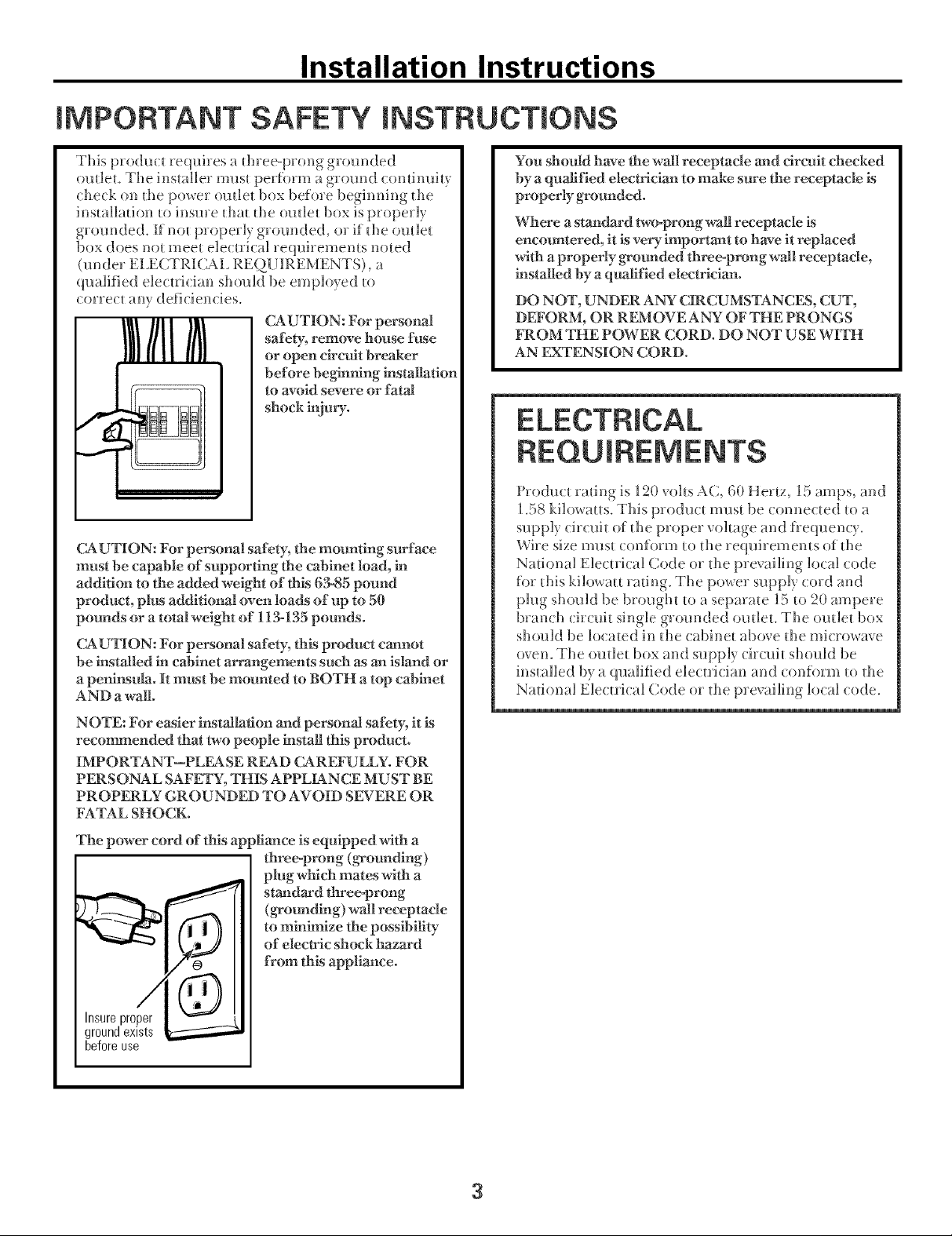
CAUTION: For personal
safety, remove house fuse
or open circuit breaker
before begh'lrfing irlstallafion
to avoid severe or fatal
shock kijury.
CAUTION: For personal safety, the mounting surface
must be capable of supporting the cabinet load, irl
addition to the added weight of this 53-85 potmd
product, plus additional oven loads of up to 50
pounds or a total weight of 113-135 pounds.
CAUTION: For personal safety, this product cannot
be installed ir_cabinet arrangements such as an island or
a peninsula. It must be mounted to BOTH a top cabinet
AND a wall.
You should have the wall receptacle and circuit checked
by a qualified electrician to make sure the receptacle is
properly grounded.
Where a standard two-prong wall receptacle is
encom_tered, it is very important to have it replaced
with a properly g_ounded three-prong wall receptacle,
installed by a qualified electrician.
DO NOT, UNDER AN_ CIRCUMSTANCES, CUT,
DEFORM, OR REMOVE ANY OF THE PRONGS
FROM THE POWER CORD. DO NOT USE WITH
AN EXTENSION CORD.
ELECTRICAL
REOUIREMENTS
Product rating is 12(1 volts AC, 6(t Hertz, 15 amps, and
[.58 kilox_atts. This p5odu(t must be (onue(ted to a
supply circuit of d_e proper voltage and h:equen(y
Wire size must conform to the re(]uiremems of the
Nathma] Electrical Code 555the prevailing local code
for this kilo_att rating The pox_er supply cord and
plug should be brought to a separate 15 to 2(1 ampere
bran( h (ir(uit single grom-bded ()inlet, The ()inlet 1)55×
should be lo(;:4ted in the cabinet above the u]icro_a_e
o_en, The omlet box and supply (::h'(uit should be
installed b) ra qualified electrician and conform to fl_e
National Electrical Code 555the prevailing local code.
NOTE: For easier installation and personal safety, it is
recommended that two people h_stall this product.
IMPORTANT--PLEASE READ CAREFULLY. FOR
PERSONAL SAFETY, THIS APPLIANCE MUST BE
PROPERLY GROUNDED TO AVOID SEVERE OR
FATAL SHOCK.
The power cord of this appliance is equipped with a
threeoprong (g_'oundlng)
plug which mates with a
staridard three-prong
(g_ounding) wall receptacle
to minimize the posslbifity
of electric shock hazard
from this appliance.
Insure proper
ground exists
before use
3
Page 4
Installation Instructions
HOOD EXHAUST
NOTE: Read these next two pages only if you plan to vent your exhaust to the
outside. If you plan to recirculate the air back into the room, proceed to page 6.
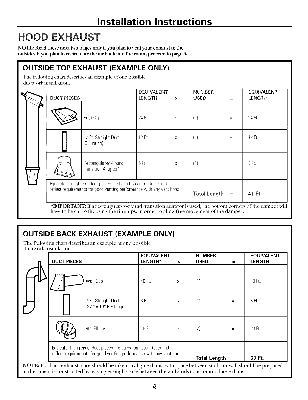
OUTSIDE TOP EXHAUST (EXAMPLE ONLY)
Tile fi)llo_fing chart des(rihes an example of one possihle
du(twork installation.
EQUWALENT NUMBER
DUCT PgECES
12Ft.StraightDuct 12Ft.
RoofCap 24 Ft.
(6" Round)
TransitionAdaptor*
Rectanguhr-to-Round 5Ft.
Equivalentlengthsofduct piecesare basedonactualtests and
reflectrequirementsfor goodventingperformancewith anyventhood.
*IMPORTANT: If a rectangular-to-round transition adaptor is used, the bottom corners of the damper will
have to he (tit to fit, using tile tin snips, in order to allow free inovelnent of the dalnper.
LENGTH x USED
OUTSIDE BACK EXHAUST (EXAMPLE ONLY)
(1)
(1)
(1)
Total Length
EQUIVALENT
LENGTH
24 Ft.
12Ft.
5Ft.
41 Ft.
The following chart des(rihes an example of one possihle
du(twork installation.
EQUIVALENT NUMBER EQUIVALENT
LENGTH* x USED = LENGTH
_Wall Cap
DUCT PIECES
[
Equivalentlengthsof ductpiecesare basedonactualtests and
reflectrequirementsforgoodventingperformancewith anyvent hood.
NOTE: For ha('k exhaust, care should he taken to align exhaust with spa(e hetween studs, or wall should he prepared
at the tilne it is constructed by leaving enough space between the wall studs to accolnlnodate exhaust.
3W' x 10" Rectangular)
90° Elbow
40 Ft. x (1) = 40 Ft.
3 Ft. x (1)3 Ft.StraightDuct
10Ft. x (2) =
Total Length = 63 Ft.
3 Ft.
20Ft.
4
Page 5
Installation Instructions
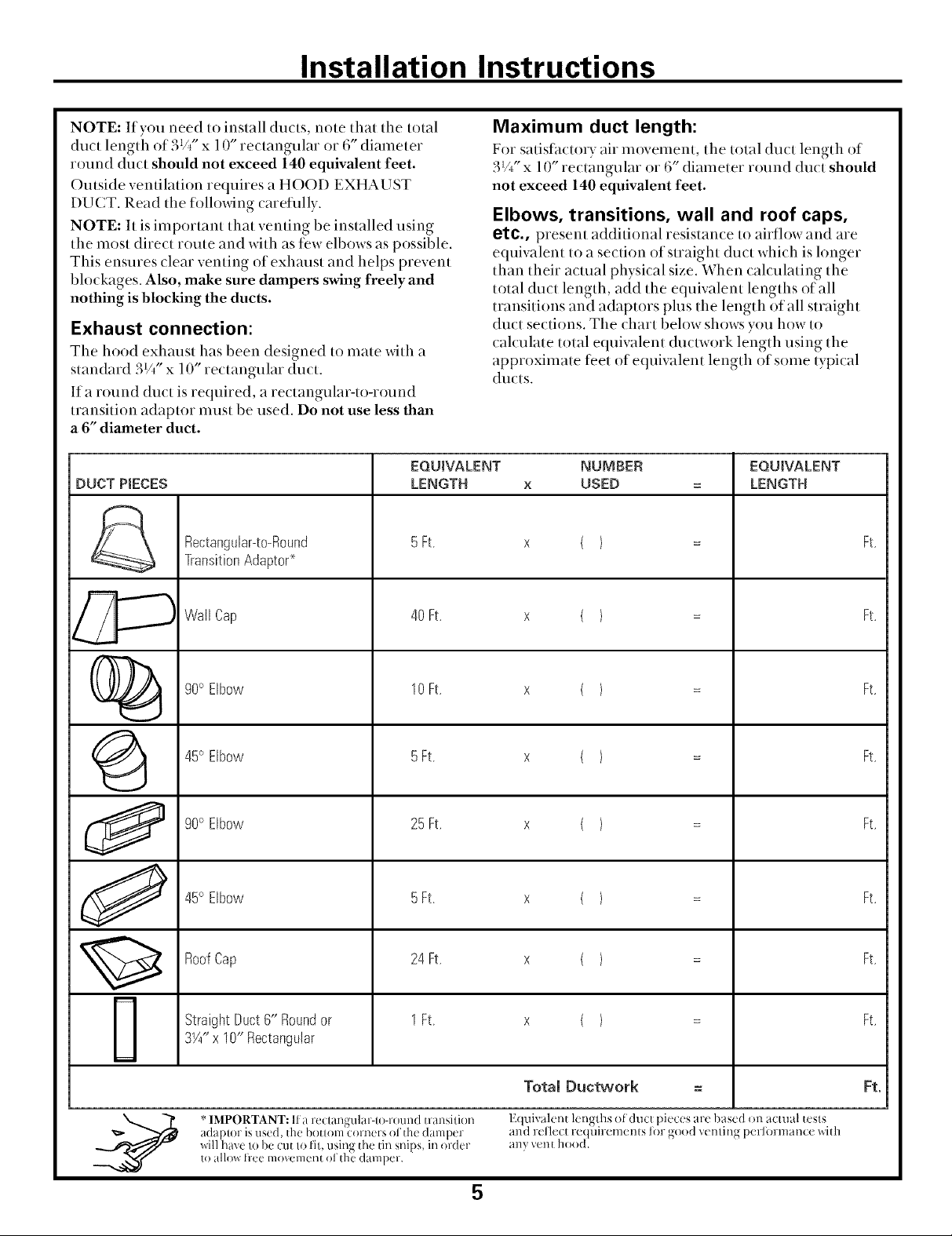
NOTE: If you need to install ducts, note that the total
duct length of 3VYx 10" rectangular or 6" diameter
round duct should not exceed 140 equivalent feet.
Outside ventilation requires a HOOD EXHAUST
DU(T. Read the folloxdng careflflly.
NOTE: It is important that venting be installed using
the most direct route and with as ti_welbows as possible.
This ensures clear venting of exhaust and helps prevent
blockages. Also, make sure dampers swing freely and
nothing is blocking the ducts.
Exhaust connection:
The hood exhaust has been designed to mate with a
standard 3V/' x 10" rectangular duct.
If a round duct is required, a rectangular-to-round
transition adaptor must be used. Do not use less than
a 6" diameter duct.
EQUIVALENT NUMBER EQUIVALENT
DUCT PtECES LENGTH x USED = LENGTH
Rectangular-to-Round 5Ft. x ( } = Ft.
TransitionAdapto¢
Maximum duct length:
For satisth{to D air movement, the total duct length of
3_/_" x 10" rectangular or 6" diameter round duct should
not exceed 140 equivalent feet.
Elbows, transitions, wall and roof caps,
etc., present additional resistance to airflow and are
equiwdent to a section of straight duct which is longer
than their actual physical size. When calculating the
total duct length, add the equivalent lengths of all
transitions and adaptors plus the length of all straight
duct sections. The chart below shows you how to
calculate total equivalent duowork length using the
approximate tibet of equivalent length of some typical
ducts.
Wail Cap 40 Ft. x { ) = Ft.
()_ go°Elbow 10Ft. x ( ) = Ft.
{_ 45° Elbow 5Ft. x ( ) = Ft.
90° Elbow 25 Ft. x ( ) = Ft.
45° Elbow 5Ft. x ( ) = Ft.
RoofCap 24Ft. x ( ) = Ft.
StraightDuct6" Roundor 1Ft. x ( ) = Ft.
3W*x 10" Rectangular
Total Ductwork = Ft.
adaplor is used, th( botlom Corners of the dam )(r and r_ l'lecI te( Uirements lbr good vc n/ing perlormance with
will have Io be cut to fil, using the tin snips, in order anx vent hood.
* IMPORTANT: lla r_'__lan_ular-I()-l-()ulld tl-ansiti()n E( uivalent 1(nNhs of dllcl 1)i¢ (:€s arc based ()i1 actual tcsls
to all{*_ free moxement of th_ damper.
5
Page 6
Installation Instructions
DAMAGE - SHmPMENT/
* If the unit is damaged in shipment, re_uvn d_e unh
_o d_e s_ore h_whhh h was bough_ for repair or
* If the unit is damaged by the customer, rep_ir 05
veplacemem is d_e responsibility of d_e _us_omer.
ff the unh is damaged by the installer (if od_er
be made by a5v_Hsgemem be_weesr5 ( us_omer a55(]
is_ss_allev.
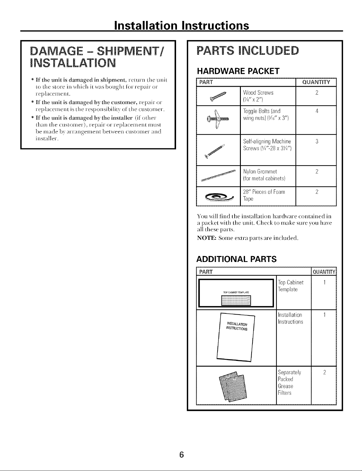
PARTS INCLUDED
HARDWARE PACKET
PART QOANTITY
WoodScrews 2
(Y/' x 2")
ToggleBolts(and 4
wingnuts)(_(' x3'9
Self-aligningMachine 3
Screws(IA"-28x 31//9
NylonGrommet 2
(formetalcabinets)
28" Piecesof Foam 2
Tape
You will find the installation hardware contained in
a packet with the unit. Check to make sure you have
all these parts.
NOTE: Some extra parts are included.
ADDITIONAL PARTS
PART
TopCabinet
Template
Installation
Instructions
Separately
Packed
Grease
Filters
QUANTIFY
1
6
Page 7
Installation Instructions
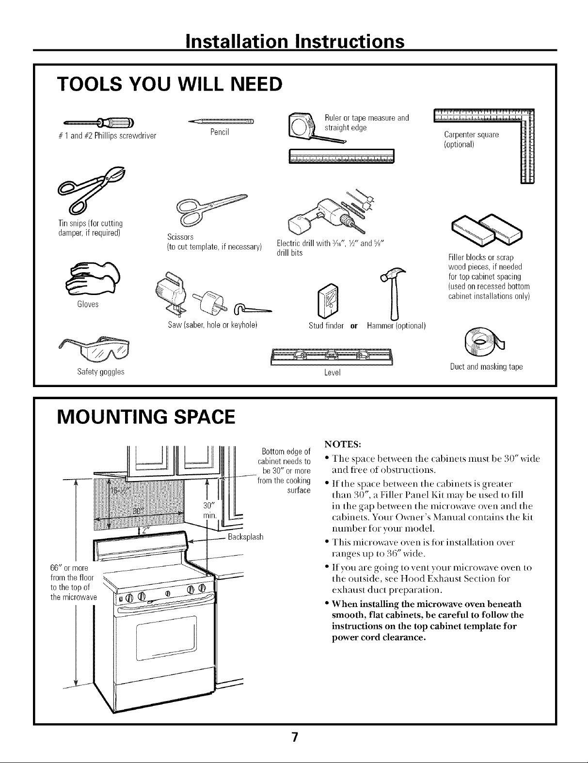
TOOLS YOU WILL NEED
# 1 and#2Phillipsscrewdriver
Tinsnips(forcutting
damper,if required)
Gloves
Scissors
(tocuttemplate,if necessary)
Pencil
Rulerortapemeasureand
t edge
Electricdrill with ¾_" VS"and%"
drill bits
(optional)
Fillerblocksor scrap
woodpieces,if needed
fortop cabinetspacing
(usedonrecessedbottom
cabinetinstallationsonly)
Saw(saber,holeor keyhole)
Safetygoggles
MOUNTING SPACE
66" ormore
fromthe floor
tothe top of
the microwave
cabinetneedsto
fromthe cooking
Backsplash
Bottomedgeof
be30" or more
surface
Studfinder er Hammer(optional)
Level
NOTES:
Ductandmaskingtape
• Tile space betweei] tile cabiilets inust be 30" wide
aild flee r)f r)bstructir)ils.
" If the space betweei] the cabinets is greater
than 30", a Filler Panel Kit inay be used to fill
in the gap betweei] the iniciow, tve oven and the
cabinets. Your Owner's Manual contains the kit
iminber for your inodel.
" This iniciow:tve ()veil is fi)r installation over
ranges up to 36" wide.
" If you are going to vent your iniciow, tve oven to
the outside, see Hood Exhaust Section fi)r
exhaust duct preparation.
• When installing the microwave oven beneath
smooth, flat cabinets, be careful to follow the
instructions on the top cabinet template for
power cord clearance.
7
Page 8
Installation Instructions
I- PLACEMENT OF THE MOUNTING PLATE
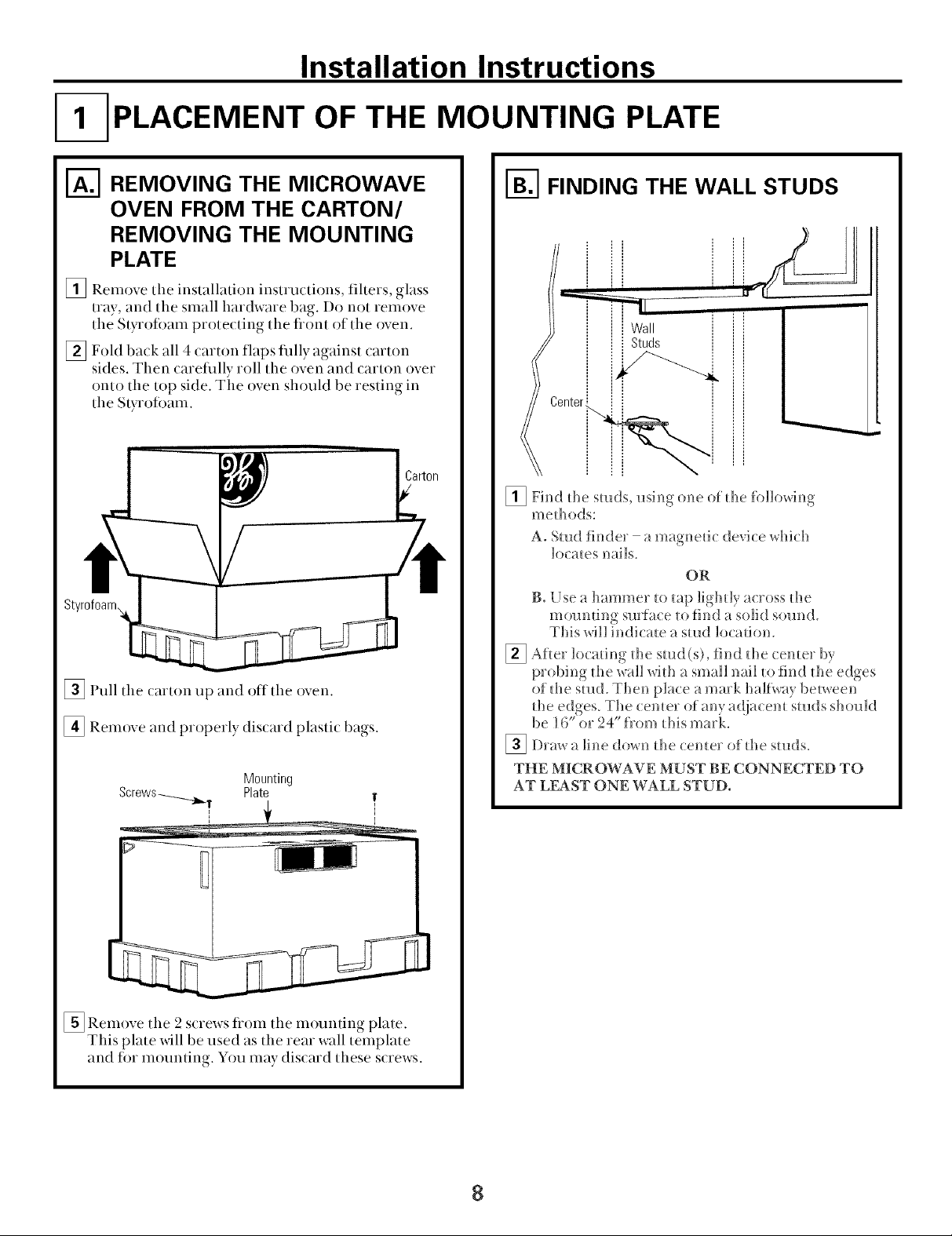
I'_ REMOVING THE MICROWAVE
OVEN FROM THE CARTON/
REMOVING THE MOUNTING
PLATE
[] Remove tile installation instructions, filters, glass
tray, and the small hardware bag. Do not remove
the Styroli)am protecting the flont of tile oven.
[] Fold back all 4 carton flaps flllly against carton
sides, Then carefiflly roll the oven and carton over
onto the top side, The oven should be resting in
the Styroloam.
[] Pull tile carton up and off tile oven.
[] Remove and properly discard plastic bags.
Mounting
Plate
I-_ FINDING THE WALL STUDS
A. Stud finder - a magnetic device which
loca_es nails.
OR
B. Use a hammer _omp lighdy across d_e
mounting suri_ce _ofind a solid soun(L
This will indicate a stud location.
[] Afler locating d_e stud(s), find _he cemer by
probing d_e wall wid_ a small nail _o l_h_dd_e edges
of d_e stud. Then place a mark half_ay between
the edges. The cemer of any adjacen_ studs should
be 16" or 24" from dfis mark.
[]Draw a line down d_e (emer of d_e studs.
THE MICROWAVE MUST BE CONNECTED TO
AT LEAST ONE WALL STUD.
[] Remove the 2 screws tiom the mounting plate.
This plate will be used as the rear wall template
and ti)r mounting. You may discard these screws.
8
Page 9

Installation Instructions
DETERMINING WALL PLATE LOCATION UNDER YOUR CABINET
Plate position - beneath flat bottom
cabinet
MountingPlateTabs
i the CabinetBottom
-::
At least 30", up to 36"
Plate position - beneath framed recessed
cabinet bottom
Mounting Plate Tabs
Touching the Back
Frame
IIIFL
tl
30" to Cooktop
Plate position - beneath recessed bottom
cabinet with front overhang
Mounting Plate with
Tabs Below Cabinet
Bottom the Same
Distance as the Front
_gDepth
tt
tt
30"to Cooktop
Your cabinets may have decorative trim that interferes
with the microwave installation. Remove the decorative
trim to install the microwave properly and to make it
level.
THE MICROWAVE MUST BE LEVEL.
Use a level to make sure the cabinet bottom is level.
If the cabinets have a flont overhang only, with no
back or side flame, install the mounting plate down
the same distance as the flont overhang depth. This
will keep the microwave level.
[] Measure the inside depth of the flont overhang.
[] Drmva horizontal line on the back wall an equal
distance below the cabinet bottom as the inside
depth of the fiont overhang.
[] For this type of installation with fiont overhang only,
align the mounting tabs with this horizontal line, not
touching the cabinet bottom as described in Step D.
9
Page 10

Installation Instructions
ALIGNING THE WALL PLATE
Hole
) (
t
I Draw a Vertca
i LineonWall
u_-- fromCenterof
1
HoleC J;
CAUTION: Wear gloves
to avoid cutting fingers on
sharp edges.
[] Draw a vertical line on the wall at tile center of the 30"
wide space.
[] Use tile mortaring plate as the template tot the rear
wall. Place tile mounting plate on the wall, making
sure that the tabs are touching the bottom of the
cabinet. Line up the notch and center line on
the mounting plate to the center line on the wall.
[] While holding the mounting plate with one hand,
draw drcles on the wall at holes A, B, ( and D (see
illustration above/aculal plate marked with rerows).
Four holes must be used for mounting.
i T°pCabinet ._
%,"
HoleD ',
NOTE: Holes C and D are inside area E. If neither
C nor D is in a stud, find a stud somewhere in area E
and draw a fifth circle to line up with the stud. It is
important to use at least one wood screw mounted
firmly in a stud to support the weight of the tnicrowave.
Set the mounting plate aside.
Drill holes on the drcles. If there is a stud, drill a _)&_"
[]
hole tot wood soews. For holes that don't line up with a
stud, drill a %" hole lot toggle bolts.
NOTE: DO NOT MOUNT THE PLATE AT THIS
TIME.
10
Page 11

Installation Instructions
INSTALLATION TYPES
This microwave oven is designed lot adaptation to tile
tollowing three types of ventilation:
A. Outside Top Exhaust (Vertical Duct)
B. Outside Back Exhaust (Horizontal Duct)
C. Recirculating (Non-Vented Ductless)
OUTSIDE TOP EXHAUST
(VERTICAL DUCT)
Adaptorin Placefor
Outside TopExhaust
(Choose A, B or C)
NOTE: This microwave is shipped assembled tot Outside
Top Exhaust (except fin non-vented models). Select tile
type of ventilation required tot your installation and
proceed to that section.
OUTSIDE BACK EXHAUST
(HORIZONTAL DUCT)
RECIRCULATING
(NON-VENTED DUCTLESS)
11
A Charcoal Fiher Accessory
Kit is required fin the non-
vented exhaust. (See your
Owner's Manual lot tile kit
ntlulbei.)
Page 12

Installation Instructions
OUTSIDE TOP EXHAUST (Vertical Duct)
INSTALLATION OVERVIEW
A 1. Attach Mounting Plate to Wall
A2. Prepare Top Cabinet
A3. Check Damper Operation
A4. Mount Microwave Oven
A5. Adjust Exhaust Adaptor
A6. Connect Duc/work
I-_ ATTACH THE MOUNTING
PLATE TO THE WALL
_=
\
Attach the plate to tile wall using toggle bolts. At least
one wood screw must be used to attach the plate to a
wall stud.
[] Remove tile toggle wings flom the bohs.
[] Insert the bolts into the mounting plate
through tile holes designated to go into (h)_vall
and reattach the toggle wings to ¾" onto each bolt.
To use toggle bolts:
SpacingforToggles
MoreThanWall
+l..-.[.--Th ckness
Mounting
Plate
BoltEnd
[] Place tile mounting plate against the wall and
insert tile toggle _dngs into the holes in the wall to
I_lount the plate.
NOTE: Befine tightening toggle bohs and wood
screw, make sure the tabs on the mounting plate
touch the bottom of the cabinet when pushed
flush against the wall and that the plate is properly
centered under the cabinet.
CAUTION: Be careflfl to avoid pinching fingers
between the back of the mounting plate and the wall.
[] Tighten all bolts. Pull the plate away flom the wall
to help tighten the bolts.
12
Page 13

Installation Instructions
USE TOP CABINET TEMPLATE
FOR PREPARATION OF TOP
CABINET
You need to drill holes for the top support screws, a
hole large enougll for tile power cord to fit through,
and a cutout large enougll for tile exhaust adaptor.
" Read tile instructions on tile TOP CABINET
TEMPI ATE.
• Tape it underneath the top cabinet.
• Drill tile holes, following tile instructions on tile
TOP CABINET TEMPI,ATE.
CAUTION: Wear satety goggles when drilling holes
in the cabinet bottom.
CHECK FOR PROPER
DAMPER OPERATION
Exhaust Adaptor
BlowerPlate
(absent on models shipped
for recirculation exhaust)
MOUNT THE MICROWAVE
OVEN
FOR EASIER INSTAIJATION AND PERSONAI,
SAFETY, WE RE( OMMEND THAT TWO PEOPLE
INSTALL THIS MICROWAVE OVEN.
IMPORTANT: Do not grip or use handle
during installation.
NOTE: If your cabinet is metal, use the nylon
grommet around the power cord hole to prevent
cutting of tile cord.
NOTE: We recommend using fillet blocks if the
cabinet fiont hangs below the cabinet bottom shell
IMPORTANT: If filler blocks are not
used, case damage may occur from over
tightening screws.
NOTE: When mounting
tile ulicI'OWaVe oven,
thread power cord
through hole in bottom of
top cabinet. Keep it tight
throughout Steps 1-3. Do [] IJft inicrowave, tilt it
not pincll cord or lift oven
by pulling (ord. "-- fot_vard, and hook
• slots at back bottom
edge onto Ibm lower
tabs of mounting
plate.
_,, Backof
Microwave
• Place tile microwave in its upright position, with tile
top of tile unit thcing up.
• This microwave oven may be shipped assembled tor
top exhaust (adaptor installed) or tor recirculation
exhaust (adaptor absent).
• Make sure tape securing damper is removed and
damper pivots easily before mounting microwave.
" You xdll need to make adjustments to assure proper
alignment _dth your house exhaust duct after tile
microwave is installed.
_ Rotate flont of oven
up against cabinet
bottom.
[] Insert a self aligning screw through top center
cabinet hole. Temporarily secure the oven by
turning the screw at least two full turns after the
threads have engaged. (It will be completely
tightened later.) Be sure to keep power cord
tight. Be careful not to pinch the cord, especially
when mounting flush to bottom of cabinet.
13
Page 14

Installation Instructions
CabinetFront
CabinetBottomShelf
FillerBlock
T quivalentto
[] Insert 2 self:aligning screws
thrrmgh outer top (abinet
holes. Turn two fllll turns on
each sciew.
n
Depth
of Cabinet
Recess
ADJUST THE EXHAUST
ADAPTOR
Open the top cabinet and at{just tile exhaust adaptor
to connect tr) tile house duct.
Backof
BlowerPlate Damper Microwave
ForFront-to-Backor
Side-to-Side
Adjustment,Slidethe
ExhaustAdaptoras
Needed
I-_ CONNECTING DUCTWORK
HouseDuct
[] Tighten center
screw completely.
[] Tighten tile outer two screws to tile top of tile
microwave oven. ('vVhile tightening screws, hold
the microwave oven in pla(e against the wall and
the top cabinet.)
1400and 1600Series 1800Series
[] Install grease filters. See the Owner's Manual
parked with the mi(rowave.
[]Extend tile hr)use duct dr)wn tr) connect to
tile exhaust adaptor.
[] Seal exhaust du(t.joints using du(t tape.
14
Page 15

Installation Instructions
OUTSIDE BACK EXHAUST (Horizontal Duct)
INSTALLATION OVERVIEW
B1. Prepare Rear Wall
B2. Attach Mounting Plate to Wall
B3. Prepare Top Cabinet
B4. A(ljust Blower
B5. Mount the Microwave Oven
PREPARING THE REAR WALL
FOR OUTSIDE BACK EXHAUST
[] Place the mounting plate against tile rear wall and
align it with the holes drilled earlier.
[] Using a pencil, put (lots through holes/notches F,
G, H and I (see above illustration). Remove the
mounting plate and draw lines extending through
the points. This will give the location and size of the
box cutout tin the rear wall duct.
[] Use a saw (saber or keyhole) to cut out the opening.
[] Place tile microwave in its upright position with tile
top of the unit lacing up.
This microwave oven is shipped assembled ti)r top
exhaust. You will need the exhaust adaptor fin.
installation in the rear wall opening. To remove the
exhaust adaptor tiom tile microwave oven:
[] Remove tape securing damper.
_ Lift offthe
[] Remove and, blower plate
save screw _, Damper and attached
that holds *,_, adaptor flom
blower plate ,,
tO IIlicI'owave.
[] Slide exhaust adaptor to one side and remove it.
5
Page 16

Installation Instructions
_-_ PREPARING THE REAR WALL
FOR OUTSIDE BACK EXHAUST
(continued)
House
Duct
DamperSwings
[_Fit tile exhaust adaptor into the house duct as
shown. Make sure the exhaust adaptor (with the
damper) is squared up in the house duct and lines
up with the holes in the mounting plate.
[_Remove the paper f_om the sticky side of the 28"
fr)am tape. Press the sticky side onto the thce of the
exhaust adaptor. (Don't stretch the foam tape.)
Damper Hinge On Top
To use toggle bolts:
SpacingforTogglesMore
-_l_-_i_ ThanWallThickness
i
Mounting
Plate
[] Place the mounting plate against the wall and
insert the toggle wings into the holes in the wall to
mount the plate.
NOTE: Before tightening toggle bolts and wood
screw, make sure the tabs on the mounting plate
touch the bottom of the cabinet when pushed flush
against the wall and that the plate is properly
centered under the cabinet.
CAUTION: Be careflfl to avoid pinching fingers
between the back of the mounting plate and the wall.
[] Tighten all bolts. Pull the plate away flom the wall
to help tighten the bolts.
ToggleWings
B01tEnd
M0u TI
J _ Plate/%U
[_ Attach the r)ther 28" foam tape tr) the flont r)f
the mrmnting plate around both of the exhaust
r)penings where it will tr)uch the micrr)wave.
I-_ ATTACH THE MOUNTING
IiI
Attach the plate to the wall using toggle bohs. At least
one wood screw must be used to attach the plate to a
wall stud.
[] Remove the toggle wings tiom the bolts.
[] Insert the bolts into the mounting plate through the
PLATE TO THE WALL
il i
holes designated to go into (h)avall and reattach the
toggle wings to Y_" onto each bolt.
USE TOP CABINET TEMPLATE
FOR PREPARATION OF TOP
CABINET
Yrm need to drill holes for the top support screws and
a hole large enr)ugh for the power (ord to fit through.
• Read the instmctirms rm the TO1 CABINET
TEMPI,ATE.
• Tape it underneath the top (abinet.
• I)rill the hr)les, follo_dng the instructirms rm the
TOP ( ABINET TEM1 LATE.
CAUTION: Wear satety goggles when drilling holes
in the (abinet bottom.
)
)
6
Page 17

Installation Instructions
I-_ ADAPTING MICROWAVE
BLOWER FOR OUTSIDE
BACK EXHAUST
Remove and save screw that holds bh)wer motor
t 0 UlI( I'OW}lVe,
BlowerMotor
_ Micr0wave
__ Backof
-_ BI0werM0t0r
- "_ Screw
[] Careflflly pull out the bh)wer unit. The _dres
_dll extend far enough to alh)w you tr) adjust the
1)lower unit.
BEFORE: Fan Blade
Openings Facing
[] Roll the blower unit 90 ° so that fan blade
openings are lacing out the back of the
uliciowave,
BeforeRolling
Backof
Microwave
[] Place the blower unit back into the opening.
AFTER: Fan Blade
Openings Facing Back
EndB __ Ej/_I_jT_____,, _rrd A
AfterRolling
Microwave
EndA
[] Rotate bh)wer unit counterch)ckwise 180 °.
BeforeRotation After Rotation
Microwave Microwave
[] (;ently remove the xdres flom the grooves.
Reroute the _dres through grooves on other side
of the bh)wer unit.
BeforeRerouting
After Rerouting
CAUTION: Do not pull or stretch the blower
unit wiring. Make sure the wires are not
pinched.
NOTE: The blower unit exhaust
open!ngs should match exhaust
openings on rear of microwave oven.
Se(ure the bh)wer unit tr) the mi(rowave xdth
[]
the screw fl'om Step 1.
Blower Plate
I
I
[] Replace the bh)wer plate in the same position
as before with the screw.
Backof
Microwave
BlowerMotor
Screw
Wires R0uted ThroughBightSide
Wire, Routed ThroughLeft Side
17
Page 18

Installation Instructions
MOUNT THE MICROWAVE
OVEN
FOR L4SIER INSTAI,IATION AND PERSONAL
SAFETY, WE RECOMMEND THAT TWO PEOPLE
INSTALL THIS MICROWAVE OVEN.
IMPORTANT: Do not grip or use handle
during installation.
NOTE: If your cabinet is metal, use tile nylon
grommet around tile power cord hole to prevent
cutting of tile cord.
NOTE: We recommend using filler blocks if the
cabinet flom hangs below the cabinet bottom shelf.
IMPORTANT: If filler blocks are not
used, case damage may occur from over
tightening screws.
CabinetFront
CabinetBottomShelf
FillerBlock
T quivalent
Self-AligningScrew
[] Insert 2 sell:aligning screws
through outer top cabinet
holes. Turn two flfll turns on
each screw.
to Depth
ofCabinet
Recess
NOTE: When mounting
tile illi(rowave oven,
thread power cord
through hole in bottom of
top cabinet. Keep it tight
y
flu oughout Steps 1-3. Do [] Lift microwave, tilt it
not pinch cord or lift oven tinward, and hook
by pulling cord. _ slots at back bottom
edge onto Ibm lower
tabs of mounting
plate.
_ Rotate flont of oven
up against cabinet
bottoln.
[] Insert a self aligning screw through top center
cabinet hole. Temporarily seolre the oven by
turning the screw at least two full turns after the
threads have engaged. (It will be completely
tightened later.) Be sure to keep power cord
tight. Be careful not to pinch the cord, especially
when mounting flush to bottom of cabinet.
[] Tighten center
screw completely.
[] Tighten tile outer two screws to tile top of the
microwave oven. (While tightening screws, hold
tile microwave oven in place against tile wall and
tile top cabinet.)
1400and 1600Series 1800Series
[] Install grease tihers. See tile Owner's Manual
packed with tile microwave.
18
Page 19

Installation Instructions
RECIRCULATmNG (Non-Vented #uctUess}
INSTALLATION OVERVIEW
|
el. Attach Mounting Plate to Wall
C2. Prepare Top Cabinet
C3. Check Microwave Assembly
CA.A(ljust Blower
C5. Mount the Microwave Oven _ ....
C6. Install Charcoal Fiher
/
I-_ ATTACH THE MOUNTING
PLATE TO THE WALL
\
Attach the plate to the wall using toggle bolts. At
least one wood screw must be used to attach the
plate to a wall stud.
[] Remove the toggle wings flom the bolts.
[] Insert the bolts into the mounting plate through
the holes designated to go into dD_vall and
reattach the toggle wings to %" onto each boh.
To use toggle bolts:
[] Place the mounting plate against the wall and
insert the toggle wings into the holes in the wall to
mount the plate.
NOTE: Before tightening toggle bolts and wood
screw, make sure the tabs on the mounting plate
touch the bottom of the cabinet when pushed flush
against the wall and that the plate is properly
centered under the cabinet.
CAUTION: Be careflfl to avoid pinching fingers
between the back of the mounting plate and the wall.
[] Tighten all bolts. Pull the plate away flom the wall
to help tighten the bolts.
USE TOP CABINET TEMPLATE
FOR PREPARATION OF TOP
You need to drill holes for the top support screws and
a hole large enough for the power {ord to fit through.
Mounting
Plate
,,i,
SpacingforToggles
MoreThanWall
+l_-.-[.--Th ckness
Wings
BoltEnd
• Read the instructions on the TOP (ABINET
TEMPI ATE.
• Tape it underneath the top cabinet.
• Drill the holes, tollowing the instructions on the
TOP CABINET TEMPLATE.
CAUTION: Wear safety goggles when drilling holes
in the (abinet bottom.
19
Page 20

Installation Instructions
CHECK MICROWAVE ASSEMBLY
Exhaust Adaptor (absent
on models shipped for
recirculatirm exhaust
Backof
Microwave ;
• Place tile microwave in its upright position, with tile
top of tile unit lacing up.
• The microwave oven may be shipped assembled fin.
top exhaust (adaptor installed) or for recirculation
exhaust (adaptor absent),
" If tile microwave was shipped for recirculation
exhaust, skip to C5. If shipped fin top exhaust,
proceed with (4.
ADAPTING MICROWAVE
BLOWER FOR RECIRCULATION
[] Carefhlly pull out tile bh)wer unit. Tile wires
xdll extend far enough to alh)w you to adjust tile
bh)wer unit.
[] Roll tile bh)wer unit 90 ° so that fan blade
are facing toward the flrmt of the mi(rowave.
BEFORE: Fan Blade
Openings Facing
openings
[] Relnove _._ D_nper [] Lifloffthe
and save , blower plate
screw that ...... and attached
holds adaptor flom
blower the microwave.
plate to
nlicrowave.
[] Slide exhaust adaptor to one side and relnove it.
NOTE: The exhaust adaptor with damper is not
needed for recirculating models. You may want to
save theln for possible fhture use.
Remove and save tile screw that holds tile bh)wer
II1OLOI" 1o tile illiciowave.
,,
ackof
Microwave
R011
I
AFTER: Fan Blade
Forward
NOTE: Make sure wires remain routed in tile grooves
of tile motor flame.
_ BlowerPlate
_.___ Backof
<_ _ Microwave
o--....,,.._;,cO=
20
Page 21

Installation Instructions
ADAPTING MICROWAVE
BLOWER FOR
RECJRCULATJON (continued}
[] Place tile bh)wer unit back into tile opening.
CAUTION: Do not pull or stretch the blower unit
wiring. Make sure the wires are not pinched.
[]Secure blower unit to ini(iowave Xddl tile s(iew
reinoved in Step 4.
[] Replace bh)wer plate with tile screw reinoved in
Step 1.
T
1
_ Backof
o...L'_II "I Microwave
NOTE: When inounting
tile ulicrowave ()veil,
thread power cord
through hole in bottoin of
top cabinet. Keep it tight
throughout Steps 1-3. Do [] IJft inicrowave, tilt it
not pinch cord or lift oven
by pulling cord. forward, and hook
slots at back bottoin
edge onto fimr lower
tabs of inounting
plate.
/
_ Rotate flont of oven
up against cabinet
bottoln.
[] Insert a sell:aligning screw through top center
cabinet hole. Teinporarily secure tile oven by
turning the screw at least two full turns after the
threads have engaged. (It will be completely
tightened later.) Be sure to keep power cord
fight. Be careful not to pinch the cord, especially
when mounting flush to bottom of cabinet.
MOUNT THE MICROWAVE
OVEN
FOR EASIER INSTAI,I,ATION AND PERSONAL
SAFETY, WE RECOMMEND THAT TWO PEOPLE
INSTALL THIS MICROWAVE OVEN.
IMPORTANT: Do not grip or use handle
during installation.
NOTE: If your cabinet is inetal, use the nylon groininet
around the power cord hole to prevent cutting of the
cord.
NOTE: We recoininend using filler blocks if tile
cabinet tiont hangs below tile cabinet bottoin shelE
IMPORTANT: If filler blocks are not used,
case damage may occur from over tightening
screws.
CabinetFront
CabinetBottomShelf
FillerBlock
Equivalentto Depth
f CabinetRecess
Self-AligningScrew
MicrowaveOvenTop
_Attach tile inicrowave oven to tile top cabinet.
21
Page 22

Installation Instructions
MOUNT THE MICROWAVE
OVEN (continued}
[] Insert 2 self:aligning screws
through outer top (abinet
hr)les. Turn two flfll turns rm
each screw.
[] Tighten center
screw completely.
[] Tighten the outer two screws to the top of the
microwave oven. (While tightening screws, hr)ld
the microwave oven in place against the wall and
the top cabinet.
JNSTALUNG THE
CHARCOAL RLTER
[] On 1400 and 1600 Series models, remove 2 screws
on fiont of grille using a #1 Phillips screwdriver.
On 1800 Series models, remove 2 screws on top
fiont of grille using a #2 Phillips screwdriver.
[] Open the door.
[] Remove the grille.
Charcoal
¼
1400and 1600Series 1800Series
[] Install grease filters. See the Owner's Manual
parked with the mi(rowave.
Insertmesh-sidedown
Insertmesh-sideup
Page 23

Installation Instructions
BEFORE YOU USE YOUR MICROWAVE
_k4ke sllFe _he micro_%_ve o_er_ h;-_s been
installed according _o instructions.
/
Remove all packing material flom _he
mi( ro_,k2_e o_erh
['_ Install turntable and ring in cavity.
I
/
_3
[_ Read _l_e Owner's Marmal.
[_ KEEP INSTALLATK)N INSTRUCTIONS
FOR THE L()CAI_ INSPECT()R'S USE.
I
[_ Replace house fi_se or turn breaker back on.
IilIIII1/11
-_ lug power (:ord imo a dedicaled 15 _o 20 amp
ele(:_ri(:al omle_.
ground exists/
Insure proper
before use
23
Page 24

Part No. 164D3370P 129
Pub. No. 49- 40134-1
12-00 JR Printedin Korea
 Loading...