

GE JVM1665DN1BB, JVM1665DN1WW, JVM1665DN2BB, JVM1665DN2WW, JVM1665SN1SS Installation Guide
...Page 1
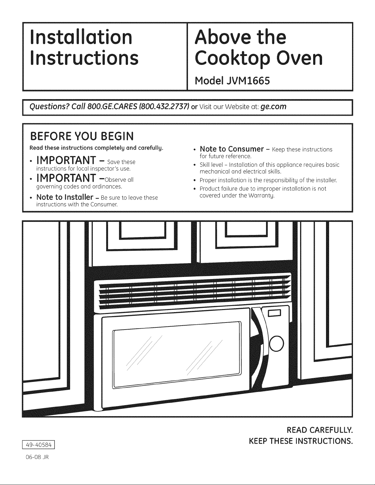
I stallati
Above the
I str
cti
BEFORE YOU BEGIN
Read these instructions completelg and carefullg.
•IMPORTANT - Sovethese
instructionsforlocolinspector'suse.
•IMPORTANT-Observeoll
governingcodesondordinonces.
• Note to Installer- Be sureto leovethese
instructionswiththeConsumer.
Cooktop Ove
Model JVMI665
Note to Consumer - Keepthese instructions
for future reference.
Skill level - Instollotion of this opplionce requires bosic
mechonicol ond electricol skills.
o
Proper instollotion is the responsibility of the instoller.
o
Product foilure due to improper instollotion is not
covered under the Worrontg.
I 49-40584 I
06-08 JR
/
/
READ CAREFULLY.
KEEP THESE INSTRUCTIONS.
Page 2
Installation Instructions
CONTENTS
General information
Important Safety Instructions ...................................... 3
Electrical Requirements .................................................. 3
Hood Exhaust ................................................................ 4, 5
Damage-Shipment/Installation .................................. 6
Parts Included .................................................................. 6
Tools You Will Need .......................................................... 7
Mounting Space ................................................................ 7
Step-bg-step installation guide
Placement of Mounting Plate .................................. 8-10
Removing the Mounting Plate ............................ 8
Finding the Wall Studs .......................................... 8
Determining Wall Plate Location ........................ 9
Aligning the Wall Plate ...................................... 10
[_ Recirculating ................................................ 19-22
Attach Mounting Plate to Wall ................ 19
Preparation of Top Cabinet ...................... 19
Adapting Blower for
Recirculation ........................................ 20, 21
Mount the Oven .................................. 21, 22
Installing the Charcoal Filter .................... 22
Before You Use Your Oven .......................................... 23
Installation Tgpes .................................................... 11-22
_ Outside Top Exhaust .................................... 12-14
Attach Mounting Plate to Wall ................ 12
Preparation of Top Cabinet ...................... 13
Assemble and Install Adapter .................. 13
Mount the Oven .................................. 13, 14
Adjust the Exhaust Adapter ...................... 14
Connecting Ductwork ................................ 14
]_ Outside Back Exhaust .................................. 15-18
Preparing Rear Wall for
Outside Back Exhaust ................................ 15
Attach Exhaust Adapter to
Oven Rear Panel ........................................ 15
Attach Mounting Plate to Wall ................ 16
Preparation of Top Cabinet ...................... 16
Adapting Blower for Outside
Back Exhaust .................................................. 17
Mount the Oven .......................................... 18
2
Page 3
Installation Instructions
IMPORTANT SAFETY INSTRUCTIONS
This product requires a three-prong grounded outlet.
The installer must perform a ground continuitg check
on the power outlet box before beginning the
installQtion to insure thQt the outlet box is properlg
grounded. If not properlg grounded, or if the outlet
box does not meet electricQI requirements noted
(under ELECTRICALREQUIREMENTS),a qualified
electriciQn should be emploged to correct ang deficiencies.
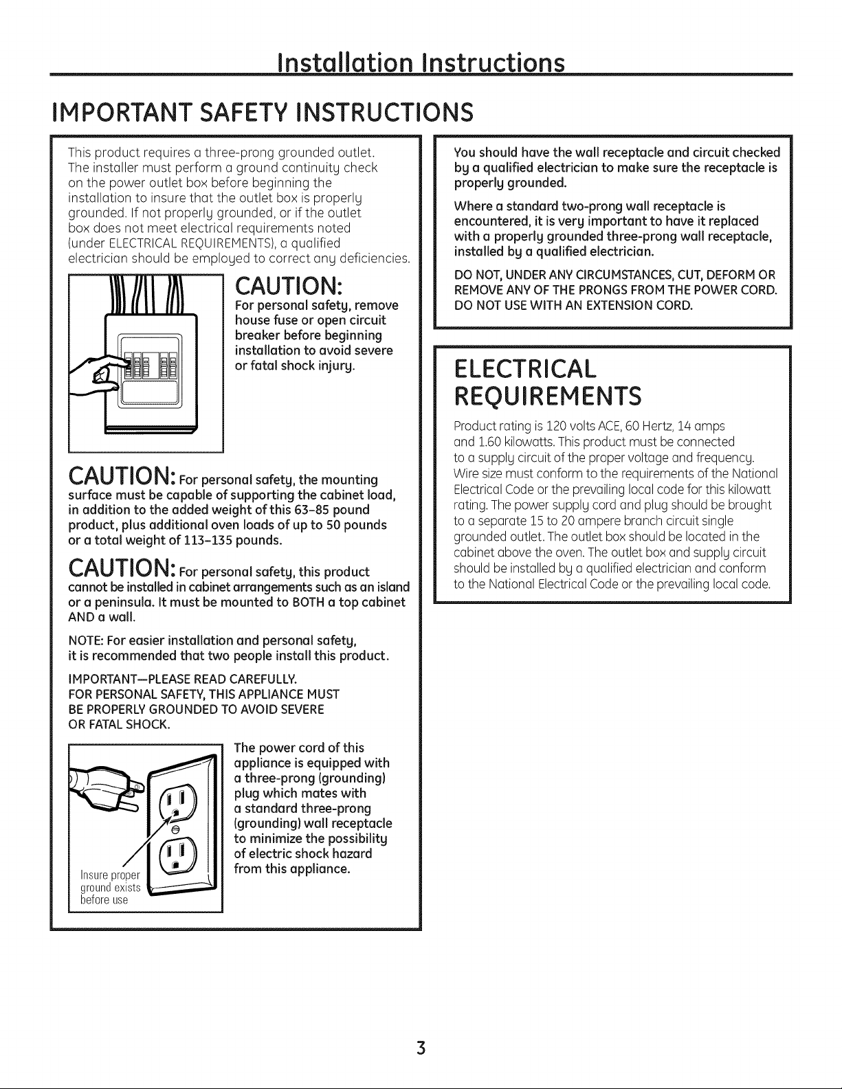
CAUTION:
For personal safety, remove
house fuse or open circuit
breaker before beginning
installation to avoid severe
or fatal shock injury.
CAUTION: Forpersonal safetg, the mounting
surface must be capable of supporting the cabinet load,
in addition to the added weight of this 63-85 pound
product, plus additional oven loads of up to 50 pounds
or a total weight of 113-135 pounds.
CAUTION: For personal safetg, this product
cannot be installed in cabinet arrangements such asan island
or a peninsula. It must be mounted to BOTHa top cabinet
AND a wall.
You shouldhave the wall receptacle and circuit checked
bg a qualified electrician to make sure the receptacle is
properlg grounded.
Where a standard two-prong wall receptacle is
encountered, it is verg important to have it replaced
with a properlg grounded three-prong wall receptacle,
installed by a qualified electrician.
DO NOT, UNDER ANY CIRCUMSTANCES, CUT, DEFORM OR
REMOVE ANY OF THE PRONGS FROM THE POWER CORD.
DO NOT USE WITH AN EXTENSION CORD.
ELECTRICAL
REOUIREMENTS
Product rating is120 voltsACE,60 Hertz,14 amps
and 1.60 kilowatts.This product must be connected
to a supplg circuit of the proper voltage and frequencg.
Wire sizemust conform to the requirements ofthe National
ElectricalCode or the prevailing local code for this kilowatt
rating.The power supplg cord and plug should be brought
to a separate 15to 20 ampere branch circuit single
grounded outlet. The outlet box should be located in the
cabinet above the oven.Theoutlet box and supplg circuit
should be installed bg a qualified electrician and conform
to the National Electrical Codeor the prevailing local code.
NOTE: For easier installation and personal safetg,
it is recommended that two people install this product.
IMPORTANT--PLEASE READ CAREFULLY.
FOR PERSONAL SAFETY,THIS APPLIANCE MUST
BE PROPERLY GROUNDED TO AVOID SEVERE
OR FATAL SHOCK.
The power cord of this
appliance is equipped with
a three-prong (grounding)
plug which mates with
a standard three-prong
(grounding) wall receptacle
to minimize the possibilitg
of electric shock hazard
Insureproper
groundexists
beforeuse
from this appliance.
3
Page 4
Page 5
Page 6
Page 7
Page 8
Installation Instructions
PLACEMENT OF THE MOUNTING PLATE
REMOVING THE OVEN FROM THE
CARTON/REMOVING THE MOUNTING
PLATE
Remove the turntable, installation instructions,
%
filters, exhaust Adapter, damper, shelf and the small
hardware bag. Do not remove the Styrofoam
protecting the front of the oven.
Fold back all 4 carton flaps fully against carton
[]
sides.Then carefully roll the oven and carton
over onto the top side. The oven should be resting
in the Styrofoam.
[_ Pullthe carton up and off the oven.
%
The mounting plate is attached to the back of the
oven. Remove the two screws holding it to the oven.
The plate will be used as the rear wall template and
for mounting the oven to the wall.
Carton
F_ FINDING THE WALL STUDS
I i
Wall
Studs
i
C_nt_rj_i
[] Findthe studs, using one of the following methods:
A. Stud finder - a magnetic device which locates nails.
OR
B. Usea hammer to tap lightly across the mounting
surface to find a solid sound. This will indicate
a stud location.
[_ After locating the stud(s),find the center by probing
the wall with a small nail to find the edges of the stud.
Then place a mark halfway between the edges.
The center of any adjacent studs should be !6"
or 24" from this mark.
[_ Draw a line down the center of the studs.
THE OVEN MUSTBECONNECTEDTO ATLEASTONE
WALL STUD.
[_ Setthe oven upright. Remove and properly discard
plastic bags and Styrofoam.
[_ Open the oven door and remove any packing
material, if present, from inside the oven.
8
Page 9
Installation instructions
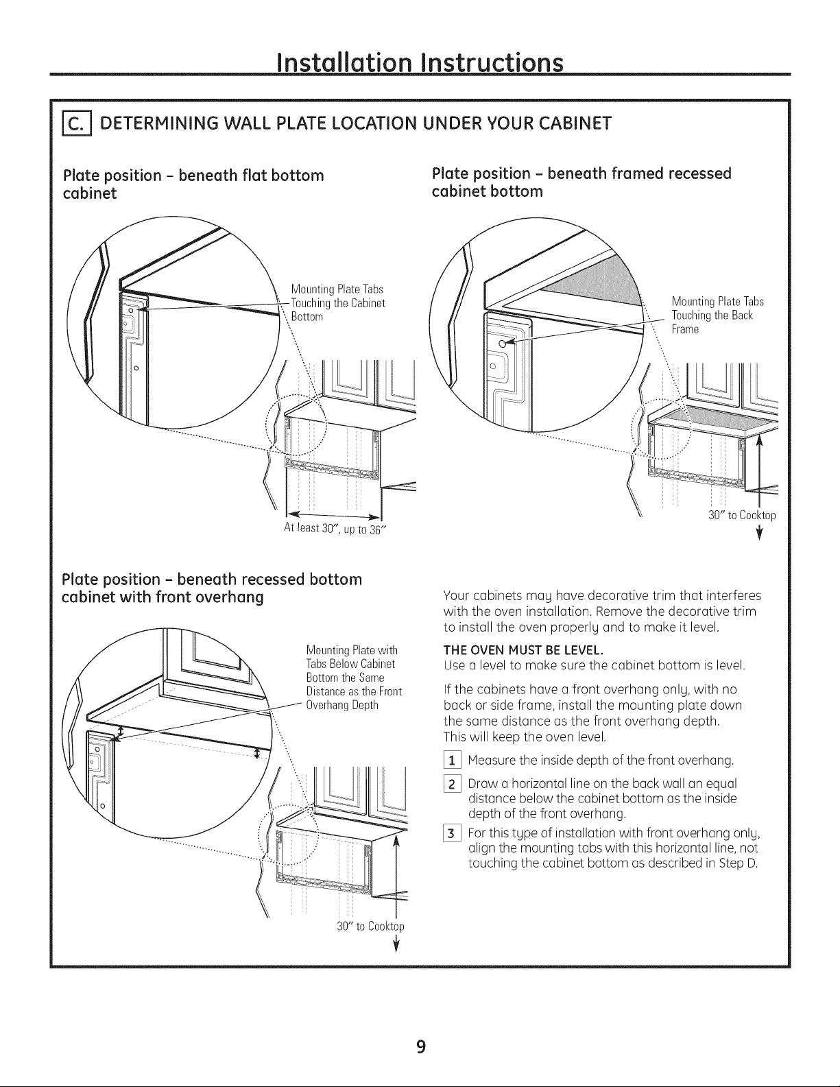
| DETERMINING WALL PLATE LOCATION UNDER YOUR CABINET
Plate position - beneath flat bottom
cabinet
MountingPlateTabs
Bottom
At least 30", up to 36"
theCabinet
Plate position - beneath framed recessed
cabinet bottom
MountingPlateTabs
TouchingtheBack
'-. Frame
s
"...
30" to Cool<top
Plate position - beneath recessed bottom
cabinet with front overhang
MountingPlatewith
TabsBelowCabinet
BottomtheSame
Distanceasthe Front
OverhangDepth
\
Your cobinets mog hove decorotive trim thot interferes
with the oven instollotion. Remove the decorotive trim
to instoll the oven properly ond to moke it level.
THE OVEN MUSTBELEVEL.
Use o level to moke sure the cobinet bottom is level.
If the cobinets hove o front overhong onlg, with no
bock or side frome, instoll the mounting plote down
the some distonce os the front overhong depth.
This will keep the oven level.
[] Heosure the inside depth of the front overhong.
[_ Drow o horizontol line on the bockwoll on equol
distonce below the cobinet bottom os the inside
depth of the front overhong.
[_ Forthis type of instollotion with front overhong only,
olign the mounting tobs with this horizontol line,not
touching the cobinet bottom os described in Step D.
30" to Cool<top
9
Page 10
Installation instructions
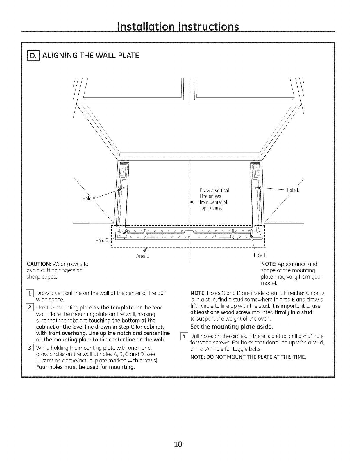
ALIGNING THE WALL PLATE
ri_-: . i[i r:
fP i _:l
\,
\A _
Hole
\\\
\
I i . ii[
,,j . uraw a veRIcal ii
' ! LineonWall
i I TopCabinet ii'
i i i
\
I I i
L......................... •..................... t_=_i
?-
[ 7 ]i
ix
I
I_ fromCenterof '_.
. I [
--_ HoleB
/
/
Hole C_
#, 4
AreaE I
CAUTION:Wear gloves to
avoid cutting fingers on
sharp edges.
[] Draw a vertical line onthe wall at the center of the 30"
wide space.
[_3 Usethe mounting plate as the template for the rear
wall. Place the mounting plate on the wall, making
sure that the tabs are touching the bottom of the
cabinet or the level line drawn in Step C for cabinets
with front overhang. Line up the notch and center line
on the mounting plate to the center line on the wall.
[_3 While holding the mounting plate with one hand,
draw circles on the wall at holes A, B,C and D(see
illustration above/actual plate marked with arrows).
Four holes must be used for mounting.
o o o
HoleD
i
NOTE:Appearance and
shape of the mounting
plate mag varg from gour
model.
NOTE:Holes Cand D are insidearea E.Ifneither Cnor D
is in a stud, find a stud somewhere in area Eand draw a
fifth circle to line up with the stud. It is important to use
at least one wood screw mounted firmly in a stud
to support the weight of the oven.
Set the mounting plate aside.
[_ Drillholes on the circles. If there is a stud, drill a s/16"hole
for wood screws. Forholes that don't line up with a stud,
drill a %" hole for toggle bolts.
NOTE:DO NOTMOUNTTHEPLATEATTHISTIME.
10
Page 11
Installation Instructions
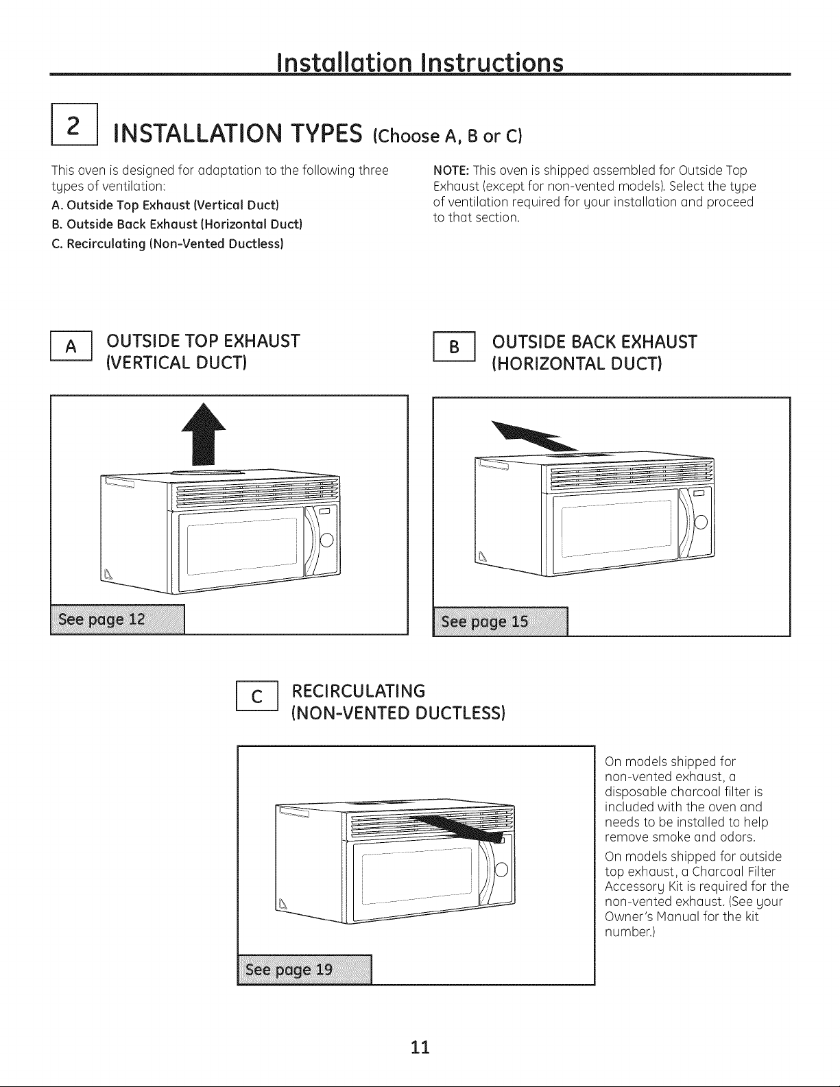
INSTALLATION TYPES {Choose A, B or C)
This oven is designed for adQptation to the following three
types of ventilation:
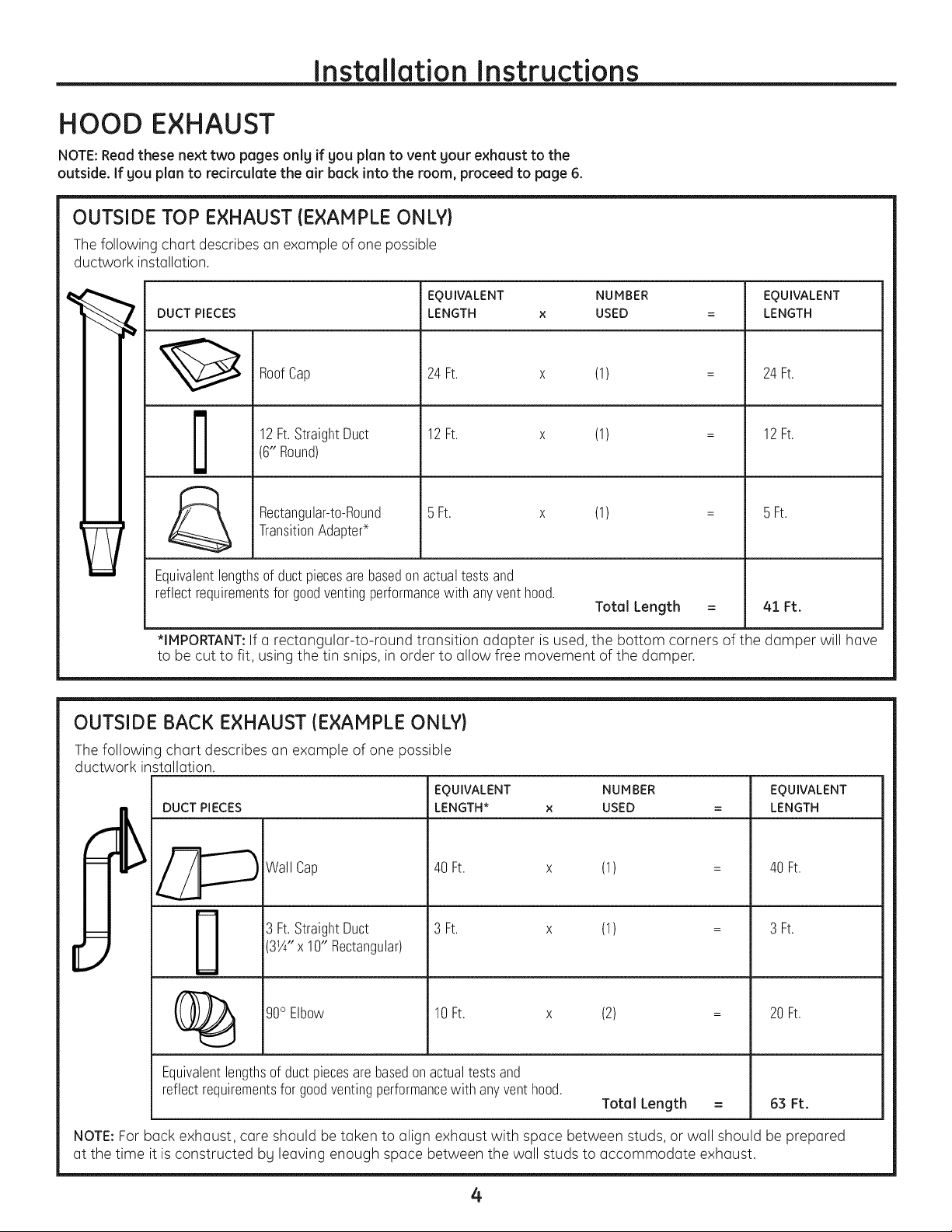
A. Outside Top Exheust (Vertical Duct}
B. Outside Beck Exheust (Horizontel Duct}
C. Redrculeting (Non-Vented Ductless}
OUTSIDE TOP EXHAUST
{VERTICAL DUCT)
NOTE:This oven is shipped assembled for Outside Top
ExhQust(except for non-vented models). Select the tgpe
of ventilQtion required for gour installQtion and proceed
to thQt section.
OUTSIDE BACK EXHAUST
{HORIZONTAL DUCT)
RECIRCULATING
{NON-VENTED DUCTLESS)
11
On models shipped for
non-vented exhQust, a
disposQble chQrcoQIfilter is
included with the oven Qnd
needs to be installed to help
remove smoke and odors.
On models shipped for outside
top exhQust, a ChQrcoQIFilter
Accessorg Kit is required for the
non-vented exhQust. (Seegour
Owner's ManuQIfor the kit
number.)
Page 12
Installation Instructions
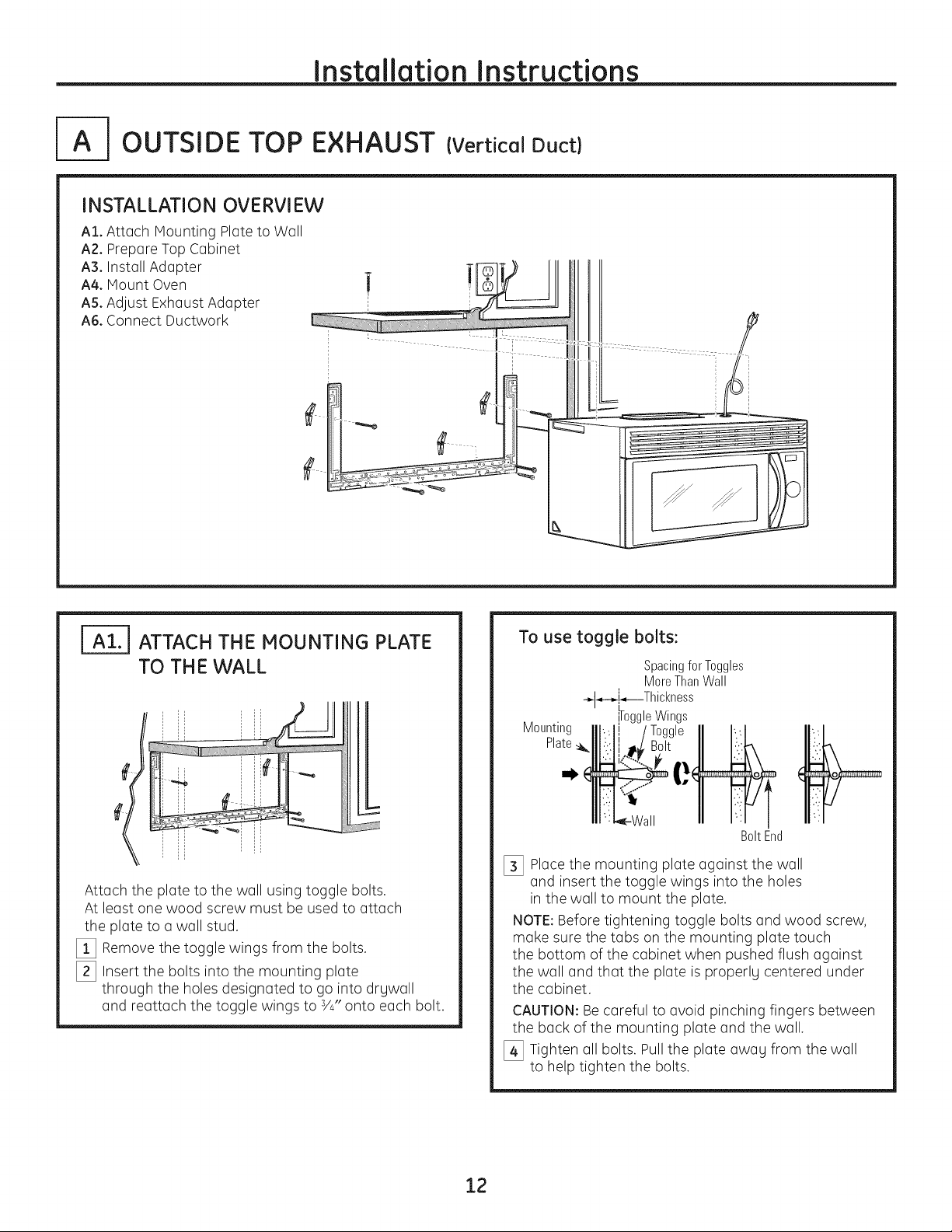
OUTSIDE TOP EXHAUST {Vertical Duct)
INSTALLATION OVERVIEW
A1. Attach Mounting Plate to Wall
A2. Prepare Top Cabinet
A3. Install Adapter
A4. Mount Oven
AS.Adjust Exhaust Adapter
A6. Connect Ductwork
ATTACH THE MOUNTING PLATE
TO TH E WALL
Attach the plate to the wall using toggle bolts.
At least one wood screw must be used to attach
the plate to a wall stud.
[] Remove the toggle wings from the bolts.
[_ Insert the bolts into the mounting plate
through the holes designated to go into drywall
and reattach the toggle wings to s/4"onto each bolt.
To use toggle bolts:
Spacingfor Toggles
MoreThanWall
-.-I_--_i_---Thicl<ness
Wings
Mounting
Plate
BoltEnd
[_ Place the mounting plate against the wall
and insert the toggle wings into the holes
in the wall to mount the plate.
NOTE:Before tightening toggle bolts and wood screw,
make sure the tabs on the mounting plate touch
the bottom of the cabinet when pushed flush against
the wall and that the plate is properly centered under
the cabinet.
CAUTION: Be careful to avoid pinching fingers between
the back of the mounting plate and the wall.
[_ Tighten all bolts. Pull the plate away from the wall
to help tighten the bolts.
12
Page 13

Installation Instructions
USE TOP CABINET TEMPLATE FOR
PREPARATION OF TOP CABINET
You need to drill holes for the top support screws,
a hole large enough for the power cord to fit through,
and a cutout large enough for the exhaust adapter.
• Readthe instructions on the top cabinet template.
• Tape it underneath the top cabinet.
• Drillthe holes, following the instructions
on the top cabinet template.
CAUTION: Wear safetg goggles when drilling holes
in the cabinet bottom.
ASSEMBLE AND INSTALL
ADAPTER
Damper
Exhaust
Adapter
i
BlowerPlate
Backof
Oven
| MOUNT THE OVEN
FOREASIERINSTALLATIONAND PERSONALSAFETY,WE
RECOHHENDTHATTWO PEOPLEINSTALLTHIS OVEN.
IMPORTANT: Do not grip or use handle
during installation.
NOTE:If gout cabinet is metal, use the nylon
grommet around the power cord hole to prevent
cutting of the cord.
NOTE:We recommend using filler blocks if the
cabinet front hangs below the cabinet bottom shelf.
IMPORTANT: If filler blocks are not used,
case damage mag occur from over
tightening screws.
NOTE:When mounting
the oven, thread power cord
through hole in bottom
of top cabinet. Keep it tight
throughout Steps 1-3.
Do not pinch cord or lift
oven bg pulling cord. [] Lift oven, tilt it
forward and hook
slots at back bottom
edge onto two lower
tabs of mounting
plate.
\
NOTE:On some models, the exhaust adapter and damper
assemblg mag alreadg be assembled to the oven.
[] Place the oven in its upright position, with the top
of the unit facing up.
NOTE:Hake sure the blower fan blades are visible
and are pointing up.
[_ Insert the tabs on each side of the damper
into the holes at the inside rear of the adapter.
[_ Attach the exhaust adapter to the blower plate
with the two bronze metal screws provided.
Make sure that the damper pivots easily before
mounting oven.
You will need to make adjustments to assure
proper alignment with gour house exhaust duct
after the oven is installed.
Rotate front of oven
up against cabinet
bottom.
13
Page 14
Installation Instructions
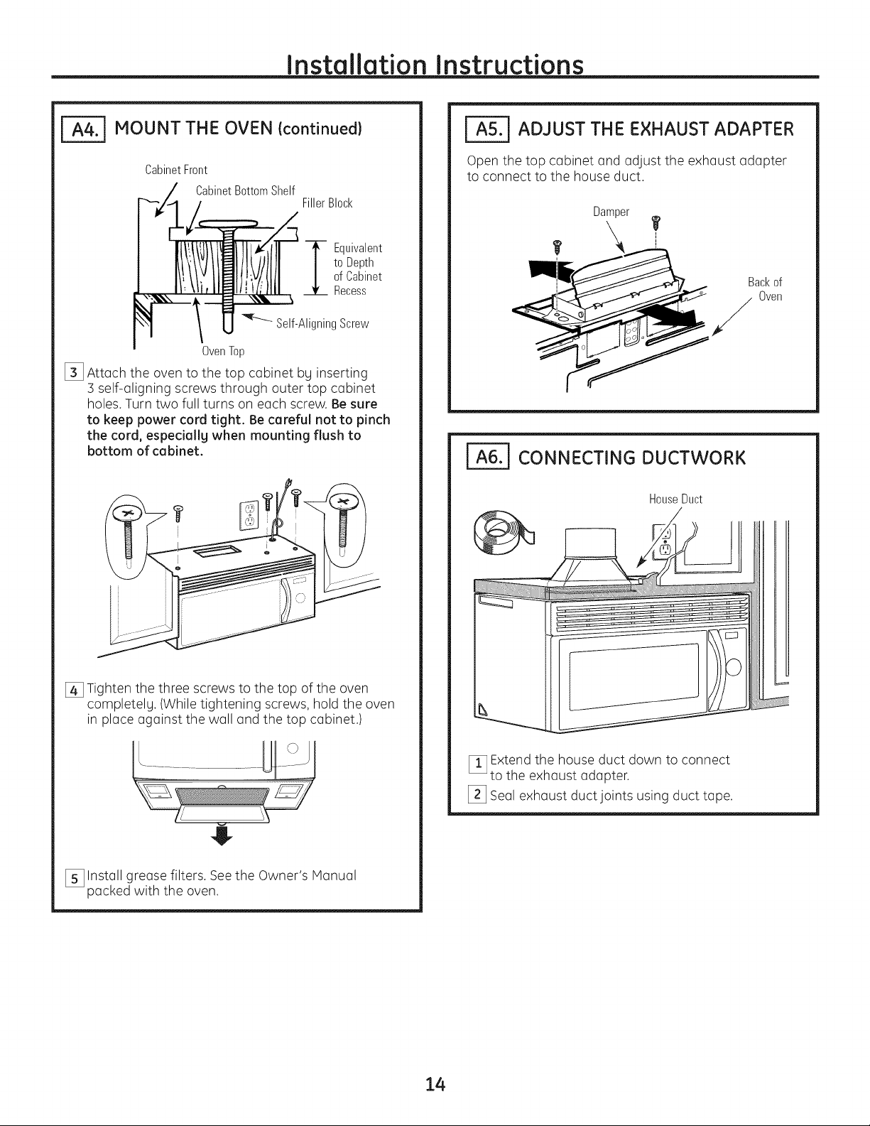
MOUNT THE OVEN {continued}
CabinetFront
CabinetBottomShelf
OvenTop
[] Attach the oven to the top cabinet by inserting
] self-aligning screws through outer top cabinet
holes. Turn two full turns on each screw. Be sure
to keep power cord tight. Be cereful not to pinch
the cord, especially when mounting flush to
bottom of cebinet.
FillerBlock
to Depth
ofCabinet
--_ Equivalent
Recess
Self-AligningScrew
__ ADJUST THE EXHAUST ADAPTER
Open the top cabinet and adjust the exhaust adapter
to connect to the house duct.
Damper
r"
CONNECTING DUCTWORK
HouseDuct
[] Tighten the three screws to the top of the oven
completelu. (While tightening screws, hold the oven
in place against the wall and the top cabinet.)
E........................
j.
[_ Install grease filters. Seethe Owner's Manual
packed with the oven.
[]Extend the house duct down to connect
to the exhaust adapter.
[_ Seal exhaust duct joints using duct tape.
14
Page 15
Installation Instructions
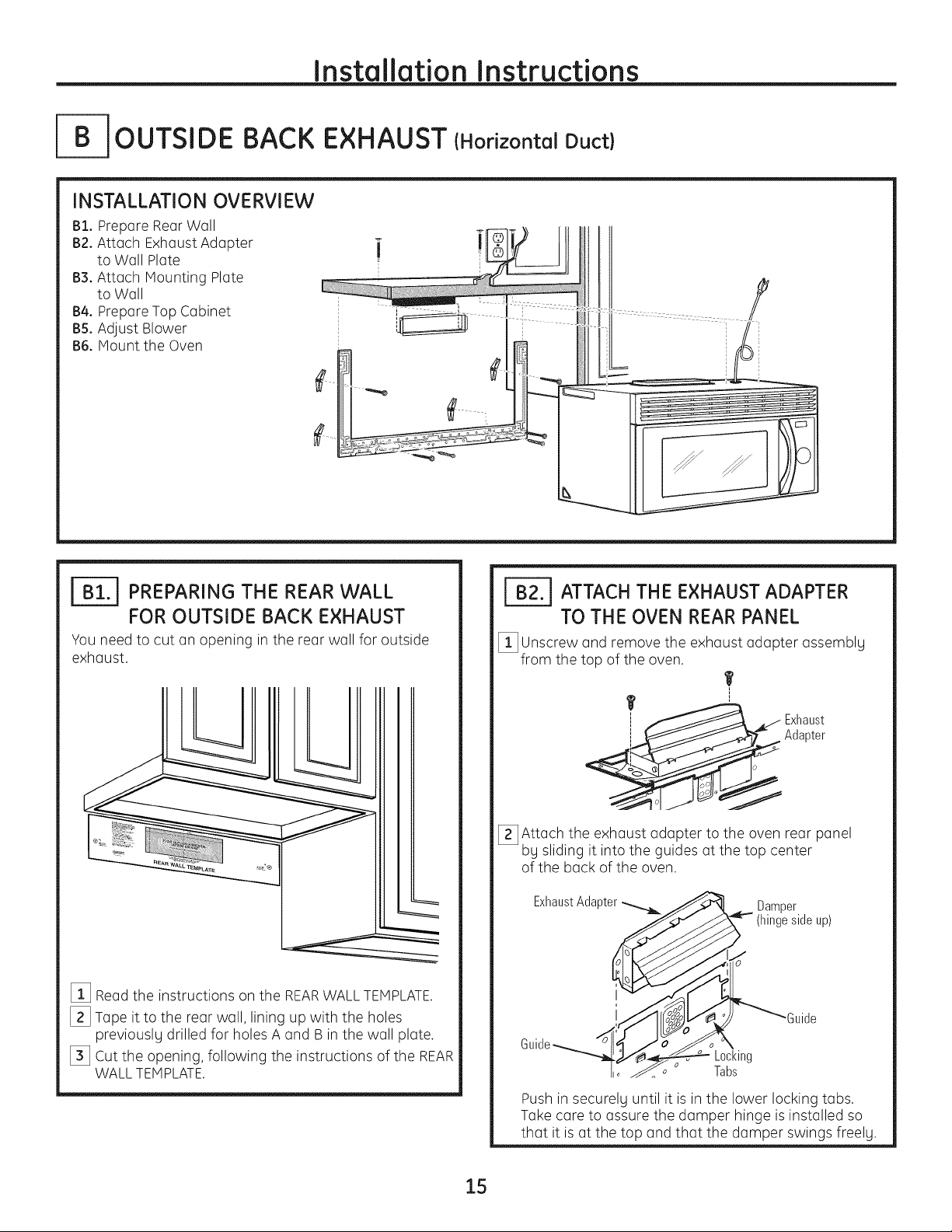
[- OUTSIDE BACK EXHAUST {Horizontal Duct)
INSTALLATION OVERVIEW
B1. Prepare Rear Wall
B2. Attach Exhaust Adapter
to Wall Plate
B3. Attach Mounting Plate
to Wall
B4. Prepare Top Cabinet
B5. Adjust Blower
B6. Mount the Oven
I-_ PREPARING THE REAR WALL
FOR OUTSIDE BACK EXHAUST
You need to cut an opening in the rear wall for outside
exhaust.
[] Readthe instructions on the REARWALLTEMPLATE.
[_ Tape it to the rear wall, lining up with the holes
previously drilled for holes A and B in the wall plate.
[_ Cut the opening, following the instructions of the REAR
WALLTEMPLATE.
ATTACH THE EXHAUST ADAPTER
TO THE OVEN REAR PANEL
[]Unscrew and remove the exhaust adapter assemblg
from the top of the oven.
T
Exhaust
Adapter
[_ Attach.....the exhaust adapter to the oven rear panel
by shdmg it into the guides at the top center
of the back of the oven.
Exhaust Adapter _ _ __ Damper
Jlo_ Tabs
15
Push in securelg until it is in the lower locking tabs.
Take care to assure the damper hinge is installed so
that it is at the top and that the damper swings freely.
Page 16

Installation Instructions
ATTACH THE MOUNTING PLATE
TO TH E WALL
Attach the plate to the wall using toggle bolts. At least
one wood screw must be used to attach the plate to
a wall stud.
[] Remove the toggle wings from the bolts.
[_] Insert the bolts into the mounting plate through
the holes designated to go into drywall and reattach
the toggle wings to s/4"onto each bolt.
To use toggle bolts:
IB4.1 USE TOP CABINET TEMPLATE FOR
PREPARATION OF TOP CABINET
You need to drill holes for the top support screws
and o hole large enough for the power cord to fit through.
• Readthe instructions on the TOPCABINETTEMPLATE.
• Tope it underneath the top cabinet.
• Drill the holes, following the instructions on the TOP
CABINETTEMPLATE.
CAUTION: Wear sofetg goggles when drilling holes
in the cabinet bottom.
SpacingforTogglesMore
-,-I_-_!_,--ThanWallThickness
M .. IToggleWings
ountmg IIl'...li 1Toggle II I'.:1
P'ate_qll:.::ll.t_B_ II I:::K
m; I-,_-Wall nn u',l I
[_ Placethe mounting plate against the woll and insert
the toggle wings into the holes in the wall
to mount the plate.
NOTE:Before tightening toggle bolts and wood
screw, make sure the tabs on the mounting plate touch
the bottom of the cabinet when pushed flush against
the wall and that the plate is properlg centered under
the cabinet.
CAUTION: Be careful to ovoid pinching fingers between
the back of the mounting plate and the wall.
[_ Tighten all bolts. Pull the plate owog from the wall
to help tighten the bolts.
BoltEnd
16
Page 17

Installation Instructions
| ADAPTING BLOWER FOR
OUTSIDE BACK EXHAUST
[] Remove the two screws that hold the blower plate
and remove the screw holding the blower motor to
the oven. Slide blower plate from under its retaining
flange.
Retaining ? "
Flange"__0"_ BlowerPlate
[_ Carefully pull out the blower unit. The wires
will extend far enough to allow Uouto adjust
the blower unit.
[] Place the blower unit back into the opening.
CAUTION: Do not pull or stretch the blower unit
wiring. Hake sure the wires are not pinched.
NOTE: The blower unit exhaust openings should
match exhaust openings on rear of oven.
[_ Replace the blower plate in the same position
as before and replace the screws for the blower
plate and blower motor.
BlowerPlateScrews
_----_---_ _ BlowerPlate
_ BackofOven
,,_--__'_-_ BlowerMotorScrew
[_ Rotate blower unit counterclockwise 180°.
BeforeRotation
AfterRotation
Backof
Oven
[_ Rollthe blower unit 90° so that fan blade
openings are facing out the back of the oven.
BeforeRollin(
Bad<
of Oven
Backof
Oven
--__ After RollingA
Oven
Backof
Oven
17
Page 18

| MOUNT THE OVEN
Installation Instructions
CabinetFront
_f J
CabinetBottomShelf
FillerBlock
-_Equivalent
to Depth
ofCabinet
Recess
FOREASIERINSTALLATIONAND PERSONALSAFETY,WE
RECOMMENDTHATTWO PEOPLEINSTALLTHIS OVEN.
IMPORTANT: DO not grip or use handle
during installation.
NOTE:If your cabinet is metal, use the nglon grommet
around the power cord hole to prevent cutting
of the cord.
NOTE:We recommend using filler blocks if the
cabinet front hangs below the cabinet bottom shelf.
INPORTANT: If filler blocks are not used,
case damage mall occur from over
tightening screws.
NOTE:When mounting
the oven, thread power
cord through hole in
bottom of top cabinet.
Keep it tight throughout
Steps 1-]. Do not pinch
cord or lift oven bu
pulling cord. _'-._,_
[] Lift oven, tilt it
forward and hook
slots at back bottom
edge onto two lower
tabs of mounting plate.
"_-- Self-AligningScrew
OvenTop
[_ Attach the oven to the top cabinet by inserting
] self-aligning screws through outer top cabinet
holes. Turn two full turns on each screw. Be sure
to keep power cord tight. Be careful not to pinch
the cord, especially when mounting flush
to bottom of cabinet.
[] Tighten the three screws to the top
of the oven completelu. (While tightening
screws, hold the oven in place against the wall
and the top cabinet.)
[_ Rotate front of oven up
against cabinet bottom.
$
[_ Install grease filters. Seethe Owner's Manual
packed with the oven.
18
Page 19

Installation Instructions
RECIRCULATING (Non-Vented Ductless}
L
t
r
E
ATTACH THE MOUNTING PLATE
TO TH E WALL
Attach the plate to the wall using toggle bolts. At least
one wood screw must be used to attach the plate to
a wall stud.
[] Remove the toggle wings from the bolts.
[_ Insert the bolts into the mounting plate through
the holes designated to go into druwall and
reattach the toggle wings to s/4"onto each bolt.
To use toggle bolts:
Spacingfor Toggles
MoreThanWall
-_l_-_i_----Thicl<ness
Mounting
Plate
O
BoltEnd
[_ Place the mounting plate against the wall
and insert the toggle wings into the holes in the wall
to mount the plate.
NOTE:Before tightening toggle bolts and wood
screw, make sure the tabs on the mounting plate touch
the bottom of the cabinet when pushed flush against
the wall and that the plate is properly centered under
the cabinet.
CAUTION: Be careful to avoid pinching fingers between
the back of the mounting plate and the wall.
[_ Tighten all bolts. Pull the plate away from the wall
to help tighten the bolts.
IC2.1 USE TOP CABINET TEMPLATE FOR
PREPARATION OF TOP CABINET
You need to drill holes for the top support screws and
a hole large enough for the power cord to fit through.
• Readthe instructions on the TOPCABINETTEMPLATE.
• Tape it underneath the top cabinet.
• Drill the holes, following the instructions on the TOP
CABINETtemplate.
CAUTION: Wear safety goggles when drilling holes
in the cabinet bottom.
19
Page 20

Installation Instructions
ADAPTING BLOWER
FOR RECIRCULATION
NOTE:The exhaust Adapter with damper is not
needed for recirculating models. You mag want
to save them for possible future use.
[] Remove and save screws that hold blower plate
and blower unit to the oven.
BlowerPlateScrews
_-----------_ ,_ BlowerPlate
, i
___ BackofOven
---- BlowerMotorScrew
[_ Slidethe blower plate from under its retaining
flange and lift it off.
Retaining
_r_ BlowerPlate
[_ Rollthe blower unit 90° so that fan blade openings
are facing toward the front of the oven.
Roll 4_
[_ Carefullg pull out the blower unit. The wires
will extend far enough to allow gou to adjust
the blower unit.
r
2O
Page 21

Installation Instructions
ADAPTING BLOWER FOR
RECIRCULATION {continued)
[_ Place the blower unit back into the opening.
CAUTION: Do not pull or stretch the blower unit
wiring. Hake sure the wires are not pinched.
[_ Replace blower plate and replace screws for blower
plate and blower motor removed in Step 1.
BlowerPlateScrews
__,_ BlowerPlate
BackofOven
F---- BlowerMotorScrew
NOTE:When mounting
the oven, thread power
cord through hole in
bottom of top cabinet.
Keep it tight throughout
Steps 1-]. Do not pinch
cord or lift oven bu pulling
cord. _____.
[_ Rotate front of oven
up against cabinet
bottom.
CabinetFront
CabinetBottomShelf
[] Lift oven, tilt it
forward and hook
slots at back bottom
edge onto two lower
tabs of mounting plate.
\
Block
| MOUNT THE OVEN
FOREASIERINSTALLATIONAND PERSONALSAFETY,WE
RECOMMENDTHATTWO PEOPLEINSTALLTHISOVEN.
IMPORTANT: Do not grip or use handle during
installation.
NOTE:If your cabinet is metal, use the nylon
grommet around the power cord hole to prevent
cutting of the cord.
NOTE:We recommend using filler blocks if the
cabinet front hangs below the cabinet bottom shelf.
IMPORTANT: If filler blocks are not used,
case damage may occur from over
tightening screws.
-_oEquivalent to Depth
f CabinetRecess
Self-AligningScrew
OvenTop
21
Page 22

Installation Instructions
MOUNT THE OVEN {continuedl
[]Attach the oven to the top cabinet by inserting
] self-aligning screws through outer top cabinet
holes. Turn two full turns on each screw. Be sure
to keep power cord tight. Be careful not to pinch
the cord, especiallg when mounting flush to
bottom of cabinet.
[] Tighten the three screws to the top of the oven
completelg. (While tightening screws, hold the oven
in place against the wall and the top cabinet.)
INSTALLING THE CHARCOAL
FILTER
[] Remove 2 screws on top of grille using a Phillips
screwdriver.
[_ Open the door 90°.
[] Remove the grille.
_J il ii ii il _ }j
[] Insert the filter into the top of the opening, between
the side support slots.
il_i iiH i iJ
JL_
Charcoal
Filter
[_ Install grease filters. See the Owner's Manual
packed with the oven.
¢%
[_ Pushthe filter all the way in where it will rest
at an angle.
[_ Replacethe grille and the 2 screws.
[] Close the door.
Insertmesh-sideup
22
Page 23

Installation Instructions
BEFORE YOU USE YOUR OVEN
IT] ake sure the oven has been installed
according to instructions.
Remove all packing material from the oven.
j F_ Install turntable and wheeled ring in cavitg, j
Read the Owner's Manual.
KEEP INSTALLATION INSTRUCTIONS
FOR THE LOCAL INSPECTOR'S USE.
'_ Replacehouse fuse or turn breaker back on.
r_ lUg power cord into a dedicated 15to 20 amp
electrical outlet.
Insureproper
groundexists/
beforeuse
23
Page 24

Printed in China
Page 25

Instrucciones
Horno para colocar
de instalaci6n
encima de la estufa
Modelo JVM1665
Preguntos? Llome 800-GE-CARES (800.432.2737) o visite nuestra p6gina en la red en: ge.com I
ANTES DE ENPEZAR
Lea estas instrucciones completa g cuidadosamente.
•IMPORTANTE- Guclrdeestclsinstrucciones
poroelusodelinspectorlocol.
•IMPORTANTE - Cumplocontodos
losc6digosy ordenonzosgubernomentoles.
• Nota para elinstalador- Aseg0rese de dejor
estos instrucciones con elconsumidor.
• Nota para el consumidor- Guordeestas
instruccionesparafuturareferencio.
• Nivel de destrezas - Loinstaloci6n de este aparoto
requiere de destrezas b6sicGsde mec6nico U electricidod.
• Loinstoloci6n opropiodo es responsobilidod del instolodor.
• Lofolio del producto debido o unGinstalGci6ninGpropiGdG
no est(i cubierto por Iogorontfo.
LEA CUIDADOSAMENTE.
GUARDE ESTAS INSTRUCCIONES.
Page 26

Instrucciones de instalaci6n
CONTENIDO
Informaci6n general
Instrucciones de seguridad importantes ....................3
Requisitos el_ctricos ........................................................3
Compono de escope ....................................................4, 5
Do6os - Envio/ Instoloci6n ............................................6
Portes incluidos ................................................................6
Herromientos que necesitor6 ........................................7
Espociode montoje ..........................................................7
Guia de instalaci6n paso por paso
C6mo colocar el plato de montaje ..........................8-10
C6mo remover elplato de montaje ........................8
C6mo encontrar madera s61idaen la pared .......... 8
C6mo determinar la Iocalizaci6n de la placa
de la pared..................................................................9
[_ Recirculaci6n ......................................................19-22
C6mo adherir el plato
de montaje a la pared ....................................19
C6mo preparar el gabinete superior ............19
C6mo adaptar el calefactor
para la recirculaci6n ................................20, 21
C6mo montar el homo ............................21, 22
C6mo instalar el filtro de carbonilla ..............22
Antes de comenzar a usar su horno ..........................23
C6mo alinear la placa de la pared ........................10
Tipos de instalaci6n ................................................11-22
[_] Escape superior ..................................
C6mo adherir la placa de montaje
a la pared ........................................................12
Preparaci6n del gabinete superior ..............13
Ensamblaje e instalaci6n del adaptador ....13
C6mo montar el horno ............................13, 14
C6mo ajustar eladaptador de escape ........14
C6mo conectar la red de conductos ............14
[_i_ Escape posterior ................................
C6mo preparar la pared posterior
para el escape posterior exterior ..................15
Fijeel adaptador de la campana
extractora al panel posterior del homo ......15
C6mo adherir el plato
de montaje a la pared ....................................16
exterior 12-14
externo
15-18
C6mo preparar el gabinete superior ............16
C6mo adaptar el calefactor para
el escape exterior posterior ............................17
C6mo montar el homo ..................................18
2
Page 27

Instrucciones de instalaci6n
INSTRUCCIONES DE SEGURIDAD IMPORTANTES
Esteproducto requiereun tomacorriente el_ctrico de tres
patas conectado a tierra. Elinstalador debe Ilevaracabo
una inspecci6n de continuidad a tierra en lacaja el_ctrica
antes de comenzar la instalaci6n para asegurar que
la caja tomacorriente est6 conectada a tierra de manera
apropiada. Sino Io est6,o sieltomacorriente no cumple
con los requisitosel_ctricos indicados (bajo la secci6n
REq)UISITOSELECTRICOS),sedeber6 recurrira un t_cnico
calificado para corregir cualquier deficiencia.
J
PRECAUClON:
Pare seguridad personal,
remueva el fusible de la casa
o abra el interruptor
de circuito antes
de comenzar la instalaci6n
para evitar descargas
el_ctricasseverasofatales.
PRECAUCION:En pos de la seguridad
personal, la superficie de montaje debe ser capaz de
soportar la carga del gabinete, adem_ls del pesoadicional
(de 63 a 85 libras)de este producto, m_lslascargas
adicionales del homo de haste 50 libraso un pesototal
entre 113 g 135 libras.
PRECAUCION:Enposdelaseguridad
personal, este producto no puede ser instalado en
sistemas de gabinetes tales como losIlamados"isles" o
"peninsulas". I_stedebe ser montado tanto a un gabinete
superior como a una pared.
Deber6 hacer que un t_cnico calificado inspeccione
el tomacorriente de pared g el circuito para asegurarse
de que el tomacorriente est_ conectado a tierra de
manera apropiada.
Donde usted encuentre un tomacorriente est6ndar
de dos patas, es mug importante que haga que el mismo
se cambie por uno de tres patas apropiadamente
conectado a tierra, instalado por un electricista
calificado.
BAJO NINGUNA CIRCUNSTANCIA NO CORTE, DEFORME, O
REMUEVA NINGUNA DE LAS PATASDEL CABLE ELI_CTRICO.
NO LO USE CON UNA EXTENSI6N ELI_CTRICA.
REQUISlTOS ELECTRICOS
La clasificaci6n del producto esde 120 vatios CA(AC),
60 hertz, 1/4amperios, g 1,60 kilovatios.Esteproducto debe
estar conectado a un circuito de suministro del voltaje
g frecuencia apropiados. Eltamano del alambre debe
conformarse a losrequisitos del National ElectricCodeo al
c6digo local en efecto para este fndice de kilovatios. Elcable
el_ctrico de alimentaci6n g elinterruptor deber6n Ilevarse
a un tomacorriente 0nico conectado a tierra de 15a 20
amperios. Lacaja del tomacorriente deber6 estar Iocalizada
en el gabinete encima del homo. Lacaja del tomacorriente
debe ser instalada por un electricista calificado g debe
conformarse al National ElectricalCodeo al c6digo local
en efecto.
NOTA:Parauna instalaci6n m6s f_cil g en pos
de la seguridad personal, se recomienda que
dos personas instalen este producto.
IMPORTANTE:
POR FAVOR, LEA CUIDADOSAMENTE. EN POS
DE LA SEGURIDAD PERSONAL, ESTEAPARATODEBE
SERCONECTADO ATIERRA APROPIADAMENTE
PARA EVITAR DESCARGAS SEVERASO FATALES.
El cable el_ctrico
de este aparato est6
equipado con un enchufe
de tres patas (con conexi6n
a tierra), Io cual requiere
que el mismo encaje con
un tomacorriente para tres
paras (con conexi6n a tierra)
de pared para minimizar
la posibilidad de descargas
el_ctricas.
3
Page 28

Instrucciones de instalaci6n
CAMPANA DE ESCAPE
NOTA:Lea las siguientes dos p(_ginassolamente si planea ventilar el escape hacia el exterior.
Si por el contrario planea recircular el aire de vuelta hacia el sal6n, continue en la p(_gina30.
ESCAPE SUPERIOR EXTERNO (EJEMPLO SOLAMENTE)
Cosiguiente toblo describe un ejemplo de uno posible
instoloci6n de red de conductos.
LONGITUD NUMERO
PARTES DEL CONDUCTO
Conductorectode 12pies
Tapadeltecho
(redondode 6")
derectanguloa redondo*
Adaptadordetransici0n
LaIongitudde las partesdelosconductosequivalentesestabasadaen pruebasrealesy reflejan
losrequisitosparaIograrunabuenaventilaciOnconcualquiercampanadeescape.
*IMPORTANTE:Sise uso un odoptodor de tronsici6n de rect6ngulo o redondo, los esquinos del fondo
del regulodor de tiros deber6n cortorse poro que encojen, usondo los tijeros de corte, poro permitir
el movimiento libre del regulodor de tiros.
EQUIVALENTE x USADO
24pies x (1)
12pies x (1)
5 pies x (1)
ESCAPE POSTERIOR EXTERNO (EJEMPLO SOLAMENTE)
Longitud total =
LONGITUD
EQUIVALENTE
24pies
12pies
5 pies
41 pies
Lo siguiente tobla describe un ejemplo de una posible
instoloci6n de red de conductos.
LONGITUD
PARTES DEL CONDUCTO EQUIVALENTE ×
_ Tapadepared 40pies x (1)
Conductorectode3pies 3 pies x (1)
(rectangularde31/4" x 10")
(_ deg0° 10pies x (2)
LaIongituddelaspartesdelosconductosequivalentesestabasadaenpruebasrealesyreflejan
losrequisitosparaIograrunabuenaventilaciOnconcualquiercampanadeescape..
NOTA:Paraelescapeposterior,sedebetenercuidadoalalinearelescapeentrelosespaciosdelospostesdevigadelapared,o lapareddeberia
serpreparadaenelmomentodesuconstrucci6ndejandosuficienteespacioentrelospostesdevigadelaparedparaacomodarelescape.
Codo
NOMERO
USADO
Longitud total = 63 pies
LONGITUD
E_UIVALENTE
40pies
3 pies
20pies
4
Page 29

Instrucciones de instalaci6n
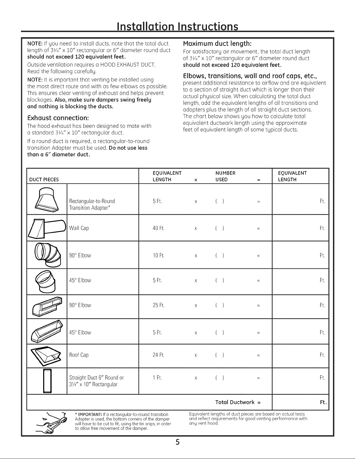
NOTA:Siusted necesitainstalar conductos, tenga
pendiente que la Iongitud total del conducto rectangular
de 31/4"x 10"o elconducto redondo de 6" de dicimetro
no debe sobrepasar 120 pies equivalentes.
La ventilaci6n externa requiere un CONDUCTODECAMPANA
DEESCAPE.Lea Iosiguiente cuidadosamente.
NOTA:Esimportante que la ventilaci6nsea instalada usando
la ruta mcisdirectag con la menor cantidad de codos posible.
Estoasegura laventilaci6n del escape y ayuda a prevenir
bloqueos.Tambi_n, cerci6resede que el regulador de tiro
pende libremente g nada bloquea losconductos.
Conexiones de escape:
La campana de escape ha sido dise_ada para encajar
con un conducto rectangular de S_'4"x 10"est6ndar.
Siun conducto redondo es necesario,sedebe usar
un adaptador de transici6n de rectangular a redondo.
No use un conducto menor de 6" de di6metro.
LONGITUD
PARTES DE CONDUCTO
&
AdaptadordetransiciOnde
rectanguloa redondo*
EQUIVALENTE
5pies
Longitud m6ximo del conducto:
Para Iograr un movimiento satisfactorio del aire,
la Iongitud total del conducto rectangular de 31/4" x 10"
o el conducto redondo de 6" de di(imetro no debe
sobrepasar 120 pies equivalentes.
Los codos, transiciones, paredes g tapas
de techo, etc., presentan resistencia adicional al flujo
de aire y son equivalentes a una secci6n de conducto
recto el cual es m(_slargo que su tamano fisico real.
Cuando calcule la Iongitud total del conducto, agregue
las longitudes equivalentes de todas las transiciones
Uadaptadores, mcis la Iongitud de todas las secciones
de conducto rectas. La tabla mcis adelante muestra c6mo
puede calcular la Iongitud aproximada de la red
de conductos usando pies aproximados de longitudes
equivalentes de algunos conductos tfpicos.
NOMERO
USADO
( )
LONGITUD
EQUIVALENTE
pies
0
J
i
m
Tapadepared
Cododeg0°
Codode45°
Cododeg0°
Codode45°
Tapadetecho
Conductorectode6" redondo
o rectangularde31/4"x 10"
40 pies
10pies
5 pies
25 pies
5 pies
24pies
1pies
( )
( )
( )
( )
( )
( )
( )
pies
pies
pies
pies
pies
pies
pies
de rect6ngulo a redondo, las esquinas del fondo del
regulador de tiros deberan sercortadas para queencajen,
* IMPORTANTE:Sise usa unadaptador de transici6n
usando lastijeras de corte, para permitir el movimiento libre
del regulador detiros.
5
Total red de conductos = pies
LaIongitud de las partes de conductos equivalentes estci basada
en pruebas reales y reflejan los requisitos para Iograr una buena
ventilaci6n con cualquier campana de escape.
Page 30

Instrucciones de instalaci6n
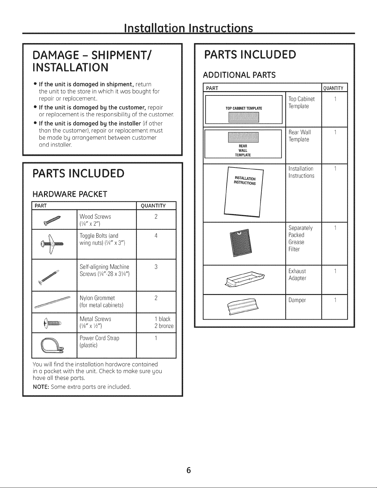
DANOS- ENVJOI
INSTALACION
• Sila unidad se daffa durante el envio, devuelva
la unidad al almac_n donde la adquiri6 para
su reparaci6n o reemplazo.
• Siel cliente doffo Io unidod, la reparaci6n
o el reemplazo es responsabilidad del cliente.
• Siel insteledor deffe Io unided (si no es el cliente),
la reparaci6n o reemplazo se debe hacer por medio
de un arreglo entre el cliente g el instalador.
PARTES INCLUIDAS
PAQUETE DE ELEMENTOS
PARTE
Tornillosde madera
(1/4"x2")
Tornillosbasculantes
(ytuercasdemariposa)
(1/44' X 34')
CANTI DAD
2
PARTES INCLUIDAS
PARTES ADICIONALES
PortE
Plantillapara
TOPCABINET TEMPLATE
REAR
WALL
TEMPLATE
INSTALLATION
INSTRUCT/ONS
el gabinete
superior
Plantilla
parala pared
)osterior
Instrucciones
de instalaciOn
Filtro
de grasa
empacado
porseparado
CANTIDAD
I
I
I
I
Tornillosde maquina
autoalineables
(1/4"-28x31/4")
Arandelaaislantede
nilOn(paragabinetes
metalicos)
Tornillosparametal
(1/8'; X 1A" )
Abrazaderadelcable
electrico(pl_istica)
Usted encontrar6 los elementos de instalaci6n
en un paquetejunto con la unidad. Inspeccione
para cerciorarse de que tiene todas las partes.
NOTA:Se inclugen algunas partes adicionales.
1negro
2 de bronce
del escape
Adaptador 1
detiro
Regulador 1
6
Page 31

Instrucciones de instalaci6n
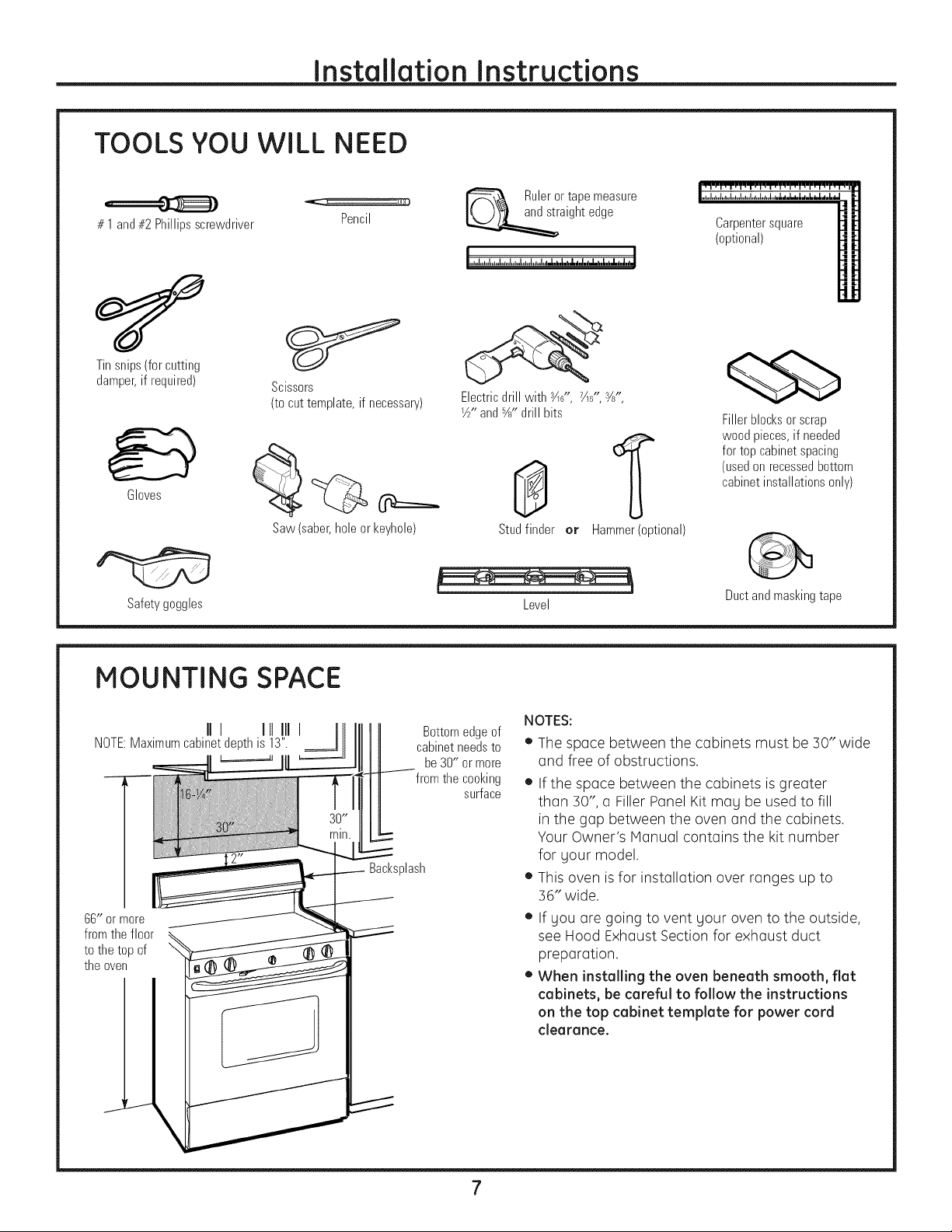
HERRAMIENTAS QUE NECESITARA
Destornilladoresdeestrella L@iz
#1y#2
Tijerasparacortarlat6n
(paracortar el regulador
detiro, si es necesario)
Guantes
Gafasdeseguridad
Tijeras(paracortar
la plantilla,si es necesario)
Sierra(desable,agujero,
odeojodecerradura)
rectay cintam6trica
Taladroel6ctricoconbrocas
deS4d", 7/ld',l/J'y%"
8
Detectorde
postesdeviga o
Nivel
unmartillo(opcional)
Escuadra
decarpintero
(opcional)
Bloquesde rellenoo
pedazosdemadera,si son
necesariospararellenarel
gabinete(usadossolamente
enla instalaci6nde
gabinetesapoyados)
Cintadeconductoso
cintaadhesivaprotectora
ESPACIO DE MONTAJE
I
66" o m_s I
desdeel I
pisohasta I
lapar!e I
m
Elextremedel
fondodel gabinete
necesitaestara
30" em_sa partir
de la superficiede
Protectorposterior
desalpicaduras
laestufa
NOTAS:
• Elespocio entre los gobinetes debe ser de 30"
de ancho g debe estar libre de obstrucciones.
• Siel espacio entre los gabinetes es magor de
30",un "Filler Panel Kit" podrfa ser necesario para
rellenar los brechas entre el horno g los gabinetes.
Su Manual del Propietario contiene el nOmero
de kit para su modelo.
• Estehomo es para ser instalado por encima
de estufas hasta 36" de ancho.
• Siusted se dispone a ventilor su homo hocio
el exterior, ver la Secci6n de Campana de Escape
para Io preparaci6n del conducto de escape.
• Cuando se instale el horno debajo de gabinetes
de fondos lisos y pianos, tenga cuidado de
seguir cuidadosamente las instrucciones en la
plantilla del gabinete superior para el espacio
de tolerancia del cable el_ctrico.
Page 32

Instrucciones de instalaci6n
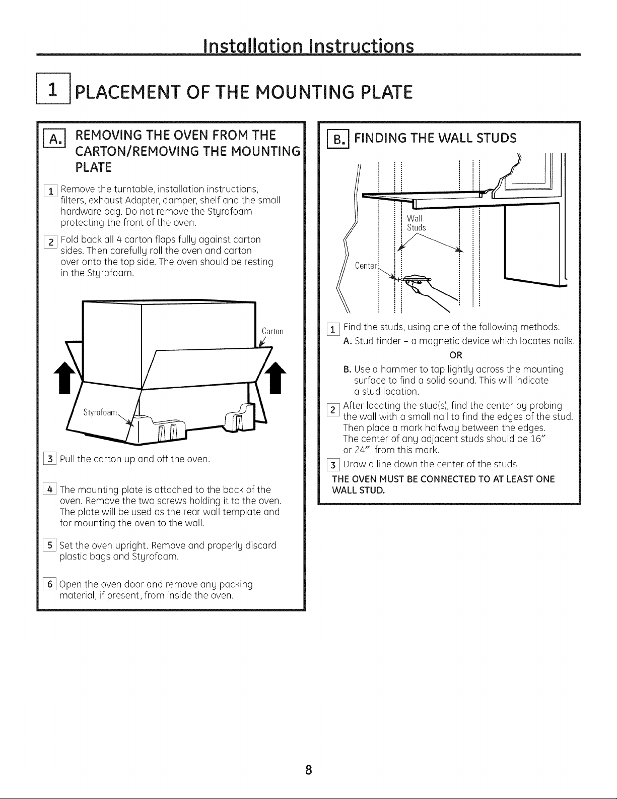
C6MO COLOCAR EL PLATO DE MONTAJE
r_ C6MO REMOVER EL HORNO
DEL EMBALAJE l COMO REMOVER
EL PLATO DE MONTAJE
%
Remueva la cajaque contiene los instrucciones
de instalaci6n, los filtros, el adaptador de escape,
el regulador de tiro, estante g la pequefia bolsa con
los elementos de instalaci6n. No remueva la espuma
de poliestireno que protege el frente del homo.
[]
Pliegue hacia atr6s las alas de la caja. Luego,
cuidadosamente ruede el horno hasta que quede
apouado sobre la parte superior. Elhomo deber6
descansar sobre la espuma de poliestireno.
[_ Tire de la caja hacia arriba g retkela del horno.
[]
Elplato de montaje est6 pegado a la parte posterior
del homo. Remueva los dos tornillos que Io sostienen
pegado al homo. El plato ser6 usado como la plantilla
de la pared posterior g para montar el horno
a la pared.
%
Pare el horno, Remueva g descarte de manera
apropiada las bolsas pl6sticas g el poliestireno,
%
Abra la puerta del horno y retire cualquier material
de empaque, si Io hay, del interior.
C6MO ENCONTRAR LOS POSTES
DE VIGA EN LA PARED
I i
Postes de vlga i
enlapared i
i
[_ Encuentre los postes, usando uno de los m@todos
siguientes:
A. Use un detector de postes - un dispositivo
magn_tico que Iocaliza clavos.
O
B. Use un martillo para golpear ligeramente
a trav@sde la superficie de montaje hasta
encontrar un sonido s61ido.Esto indicar6
que hau un poste deviga en ese lugar.
Despu@sde Iocalizar el poste o los postes de riga,
%
encuentre el centro mediante el an61isisde la pared
usando un clavo pequefio para darse cuenta de
d6nde est6n los bordes del poste. Luego coloque
una marca en el centro de los bordes. Elcentro
de cualquier poste adgacente deber6 ser entre
16"6 24" desde esta marca.
[_ Trace una Ifnea hacia abajo indicando el centro
del poste.
EL HORNO DEBE CONECTARSE POR LO MENOS
A UN POSTE DE LA PARED.
8
Page 33

Instrucciones de instalaci6n
[_ C. COMO DETERMINAR LA LOCALIZACION DEL PLATO DE MONTAJE DEBAJO
DE SU GABINETE
Posici6n del plato - debajo de gabinetes
de fondo piano
Lasorejillasdelplato de
montajetocanel fondo
del gabinete
PorIomenos30", hasta36"
Posici6n del plato - debajo de gabinetes
de fondo apogado en un marco
Lasorejillas del plato
de montaje tocan
el marco posterior
L
30" hasta la estufa
Posici6n del plato - debajo de gabinetes
de fondo apogado con frente saliente
Platodemontaje
conorejillaspordebajo
delfondodel gabinete
alamismadistancia
quela profundidad
delsaliente
\
30" hasta la estufa
Sus gabinetes podrfan tener marcos de decoraci6n
que interfieran con la instalaci6n del homo.
Remueva los marcos decorativos para instalar el horno
apropiadamente g para hacer que quede nivelado.
EL HORNO DEBEQUEDARNIVELADO.
Use un nivel para cerciorarse de que el fondo
del gabinete est(i nivelado.
Si los gabinetes tienen un saliente frontal solamente,
sin marco posterior o lateral, instale el pla del saliente.
Este mantendrci el horno nivelado.
Mida la profundidad interna del frente del saliente.
Trace una Ifnea horizontal en la pared posterior
a una distancia debajo del fondo del gabinete igual
a la profundidad interna del frente saliente.
%
Para este tipo de instalaci6n con saliente frontal
solamente, alinee las orejillas de montaje con la Ifnea
horizontal, sintocar elfondo del gabinete como
se describi6 en el Paso D.
9
Page 34

Instrucciones de instalaci6n
COMO ALINEAR EL PLATO DE MONTAJE SOBRE LA PARED
\
\
\
J
I
i Traceunelinea
I verticalenla
paredapartir
I delcentrodel
Agujer0A
Agujer0CJ
PRECAUCION:Use
guantes de protecci6n
para evitar cortaduras
en sus dedos con
los extremos filosos.
l I
I t "
o o£o o o o o o_o o o o o o_¢o9,
" ., ,_::z z:: ::z ::z :zs :s:::: s ",k--
_ _0 0 0 0_7 0 0 0_0 0 O_
^__.. _ ^ _ ^ r [______
AreaE |
i gabinetesuperior
I
i
I
i
'
----------- AgujeroB
AgujeroU
NOTA:La apariencia
Ula forma del plato
de montaje puede
variar de su modelo.
[] Trace una Ifneavertical en la pared en el centro
del espacio de 30" de ancho.
[] Useel plato de montaje como la plantilla para la pared
posterior. Coloque el plato de montaje en la pared,
cerciordndose de que las orejillas seencuentran
tocando el fondo del gabinete o la linea marcada en
el Paso C para los gabinetes con salientes frontales.
Alinee la muesca g linea del centro en el plato
de montaje con la linea de centro en la pared.
[_] Hientras sostiene el plato de montaje con una mano,
trace cfrculos en la pared en los agujeros A, B,Cy D
(verla ilustraci6n anterior / la placa real est6 marcada
con flechas). Deben usarse cuatro agujeros para
el montaje.
NOTA:Los agujeros Cg D van en el interior del
6rea E.Si ni el C ni el Dest6n en un poste de viga,
encuentre un poste en alg0n otro lugar en el 6rea E
g marque un quinto cfrculo para alinearse con el poste.
Esimportante usar por Io menos un tornillo de madera
montado firmemente en un poste para apogar el peso
del homo.
Aparte el plato de montaje.
%
Perforeagujeros en los cfrculos.Sihau un poste
de viga, perfore un agujero de 3/16" para los tornillos
de madera. Para los agujeros que no quedaron alineados
con el poste deviga, perfore un agujero de 5/8" para
los tornillos basculantes.
NOTA:TODAVJANO MONTEELPLATO.
10
Page 35

Instrucciones de instalaci6n
TIPOS DE INSTALACION
Este horno est6 dise_ado para adaptarse a los siguientes
tres tipos de ventilaci6n:
A. Escape superior exterior (Conducto vertical)
B. Escape posterior exterior (Conducto horizontal)
C. Recirculaci6n (Sin conducto de ventilaci6n)
ESCAPE SUPERIOR EXTERIOR
(CONDUCTO VERTICAL)
(EscojaA, B o C)
NOTA:Este horno es enviado ya ensamblado para
un escape superior exterior (excepto para los modelos
sin ventilaci6n). Seleccione el tipo de ventilaci6n requerido
para su instalaci6n y proceda a tal secci6n.
_1 SCAPE POSTERIOR EXTERIOR
(CONDUCTO HORIZONTAL)
I "" I
RECIRCULACION (SINCONDUCTO
DE VENTILACI6N)
En los modelos despachados
con escape sin ventilaci6n,
se incluye con el homo un filtro
de carbonilla, el cual se debe
instalar para retirar el humo
y los olores.
En los modelos despachados
con escape superior exterior,
se necesita un kit de accesorios
de filtro de carbonilla para
el sistema sin ventilaci6n.
(Consulte el Manual
del propietario para obtener
el nOmero del kit.)
11
Page 36

ESCAPE SUPERIOR EXTERIOR (Conducto vertical)
PERSPECTIVA GENERAL
DE LA INSTALACION
A1. Como adherir el plato
de montaje a la pared
A2. Prepare el gabinete superior
AS. Instale el adaptador
A4. Monte el homo
AS.Ajuste el adaptador
de escape
A6. Conecte el conducto
Instrucciones de instalaci6n
_ COMO ADHERIR LA PLACA
DE MONTAJE A LA PARED
Pegueel plato a la pared usando lostornillos
basculantes. Por Io menos un tornillo de madera debe
ser usado para pegar el plato al poste de la pared.
[] Remueva las mariposas del basculante de los
tornillos.
[_ Inserte los tornillos en el plato de montaje a trav@s
de los agujeros diseflados para ser insertados
en la pared de mamposterfa seca g pegue otra vez
las mariposas de s/,,-en cada tornillo.
Para usar los tornillos basculantes:
Espaciadoresparalos
basculantesmayores
-_l-,_-,j_que elanchodelapared
Platode
monta
[_ Coloque el plato de montaje contra la pared e inserte
las alas de mariposa en los agujeros de la pared
para montar el plato.
NOTA:Antes de apretar los tornillos basculantes
Ulos tornillos de madera, cerci6rese de que lasorejillas
en el plato de montaje toquen el fondo del gabinete
cuando son empujadas contra la pared Udeque el plato
est6 centrado apropiadamente debajo del gabinete.
PRECAUCI6N:Tenga cuidado de evitar pellizcar sus
dedos entre la parte posterior del plato de montaje
y la pared,
[_ Apriete todos los tornillos. Tire del plato
en direcci6n opuesta a la pared para ayudar
a apretar los tornillos.
'_lasdemariposa
•Pared
Extremodeltornillo
12
Page 37

Instrucciones de instalaci6n
I-_ USE LA PLANTILLA DEL GABINETE
SUPERIOR PARA LA PREPARACION
DEL GABINETE
Deber6 perforar agujeros para los tornillos de
apoyo superiores, un agujero suficientemente
grande para que el cable el@ctricoquepa,
gun recorte Io suficientemente grande coma
para que el adaptador de escape pueda ser introducido.
• Lealas instrucciones sobre la PLANTILLA
DELGABINETESUPERIOR.
• P6guelodebajo del gabinete superior.
• Taladre los agujeros, siguiendo las instrucciones
en la PLANTILLADELGABINETESUPERIOR.
PRECAUCION:Use gafas de seguridad cuando perfore
los agujeros en el fondo del gabinete.
ENSAMBLAJE E INSTALACION
DEL ADAPTADOR
Reguladordetiro
COMO MONTAR EL HORNO
PARA OBTENER UNA INSTALACION MAS FACIL Y EN POS
DE LA SEGURIDAD PERSONAL, SE RECOMIENDA C)UE
DOS PERSONAS INSTALEN ESTE HORNO.
IMPORTANTE:No agarre ni use la manija
de la puerta durante la instalaci6n.
NOTA:Si su gabinete es de metal, use la arandela
de nil6n alrededor del cable el_ctrico para evitar que
el mismo sea cortado.
NOTA: Recomendamos el uso de bloques de relleno
si el frente del gabinete cuelga por debajo del estante
del fondo del gabinete.
IMPORTANTE:Si no se usan bloques de relleno,
podrian ocurrir da_os por apretar demasiado
los tornillos.
NOTA:Cuando se encuentre
montando el homo, enrosque
el cable el_ctrico a trav_s del
agujero en el fondo del gabinete
superior. Mant_ngalo tenso
a trav_s de los Pasos del 1-3.
No pellizque el cable ni tire
del horno por el cable. _,
_i_ Levante el homo,
inclinelo hacia
adelante, g enganche
las ranuras en el
extremo inferior
posterior en dos
orejillas inferiores
del plato de montaje.
.P,atode,
__'Jcalefactor
___- _ Pa!te
I_;;i!L_ _ posterior
___ delhorno
NOTA:Enalgunosmodelos,es posiblequeeladaptador de escape
glaunidaddel reguladordetiro goest_n colocadosenel horno.
[_ Coloque el homo en su posici6n vertical, con la parte
superior hacia arriba.
NOTA: Cerci6rese de que las paletas del ventilador
calefector seen visibles g est_n orientadas hacia
arriba.
[_ Inserte las orejillas en cada lado del regulador de tiro
en los agujeros en el interior posterior del adaptador.
[_ Pegue el adaptador de escape al plato calefactor
con los dos tornillos de bronce que le proporcionamos.
Cerci6rese de que el regulador de tiro gira f6cilmente
antes de montar el homo.
Deber6 hacer ajustes para asegurarse de que existe
alineaci6n apropiada con el sistema de conductos
de su casa despu_s de la instalaci6n del horno.
[_ Gire el frente del homo contra
el fondo del gabinete.
13
Page 38

Instrucciones de instalaci6n
COMO MONTAR EL HORNO
[continuaci6nl
Frentedelgabinete
Estantedelfondodel gabinete
Bloquede relleno
la profundidad
delretroceso
Equivalentea
delgabinete
Tornilloautoalineable
Partesuperiordelhomo
[_ Pegue el horno a la parte superior del gabinete
insertando tres tornillos autoalineables a trav_s
de los agujeros exteriores superiores del horno. Gire
dos vueltas completas en cada tornillo. Cerci6rese
de mantener el cable el_ctrico estirado. Tenga
cuidado de no pellizcar el cable, especialmente
cuando se monte al nivel del fondo del gabinete.
COMO AJUSTAR EL ADAPTADOR
DE ESCAPE
Abra el gabinete superior g ajuste el adaptador
de escape para conectarlo al conducto de la casa.
Reguladordetiro
N_ __..< Parteposterior
_ /I homo
COMO CONECTAR
EL CONDUCTO
Conductodela casa
[] Apriete complemente los tres tornillos hacia la parte
de arriba del horno. (Hientras aprieta los tornillos,
mantenga el homo en su lugar contra la parte
g el gabinete superior).
!-.......................
[_ Instale los filtros de grasa. Ver el Manual
del Propietario que viene con el horno.
_!_ Extienda el conducto de la casa hacia abajo
para conectarlo con el adaptador de escape.
[_ Selle lasjuntas del conducto de escape usando
cinta adhesiva de conductos.
14
Page 39

Instrucciones de instalaci6n
FB-I ESCAPE
POSTERIOR EXTERNO (Conducto horizontal)
PERSPECTIVA GENERAL
DE LA INSTALACION
B1. Prep(Ire I(] p(]red posterior
B2. Como adherir el (]daptador
de escape (]1plato
de mont(]je
B3. Pegue el plato de montaje
a la pared
B4. Prep(Ire el g(]binete superior
B5. Ajuste el c(]lef(]ctor
B6. Monte el homo
COMO PREPARAR LA PARED
POSTERIOR PARA EL ESCAPE
POSTERIOR
Necesit(] cortor un(] obertur(] en Io pored posterior p(]r(]
el esc(]pe exterior.
FIJEELADAPTADORDELACAMPANA
EXTRACTORAAL PANELPOSTERIOR
DELHORNO
[] Des(]tornille y retire I(] unid(]d del (]d(]pt(]dor de esc(]pe
de I(] p(]rte superior del horno.
_] LeGI(]s instrucciones en I(] PLANTILLA PARALA PARED
POSTERIOR.
[_3 P_guel(] con cint(] (]dhesiv(] (] I(] p(]red posterior,
(]line6ndol(] con los (]gujeros previ(]mente perfor(]dos
p(]r(] los (]gujeros A y B en el pl(]to de I(] p(]red.
[_3 Corte I(] (]pertur(], siguiendo I(]s instrucciones
de I(] PLANTILLA PARA LA PARED POSTERIOR.
_, i Adaptador
deescape
[_3 Fije el (]d(]pt(]dor de esc(]pe (]1p(]nel posterior
del homo desliz(indolo por los gui(]s de I(] porte
superior del centro de I(] p(]rte posterior del horno.
Adaptador
deescape
Gu[a
Empuje firmemente h(]st(] que est6 en I(]s orejill(]s
de cierre inferiores. Tung(] cuid(]do de (]segur(]rse
de que I(] bis(]gr(] del regul(]dor de tiro est6 inst(]l(]d(]
de form(] que est6 en I(] p(]rte superior y que
el regul(]dor de tiro gire libremente.
__ _Gu[a
@ Orejillas
o decierre
Reguladordetiro
(bisagrahaciaarriba)
15
Page 40

Instrucciones de instalaci6n
COMO ADHERIR EL PLATO
DE MONTAJE A LA PARED
Pegue el plato a la pared usando los tornillos basculantes,
PorIo menos un tomillo de madera debe ser usado para pegar
el plato al poste de riga de la pared,
_!_ Remueva las mariposas de los tomillos.
[_ Inserte los tornillos en el plato de montaje a trav@s
de los agujeros diseflados para colocarse contra
la pared de mamposteria seca g pegue otra vez
las mariposas de s/4" a cada tornillo.
Para usar los tornillos basculantes:
Espaciadoresparalosbasculantes
_1_,-_!_,_mayoresqueelanchodelapared
IAlasdemariposa
IB4.1 USE LA PLANTILLA
DEL GABINETE SUPERIOR
PARA PREPARAR EL GABINETE
SUPERIOR
Necesita perforar agujeros para los tornillos de apouo
superiores Uun agujero suficientemente grande para
que el cable el@ctricoquepa.
• Lea las instrucciones sobre la PLANTILLA DEL GABINETE
SUPERIOR.
• P_guela debajo del gabinete superior.
• Taladre los agujeros, siguiendo las instrucciones
en la PLANTILLA DEL GABINETE SUPERIOR.
PRECAUCI6N: Use gafas de seguridad cuando perfore
los agujeros en el fondo del gabinete.
tnla1:dlli:!i!ll, tTmO;rnii,p,oOsdiib
II1' ;I_--Pared II I',1 I
[_ Coloque el plato de montaje contra la pared
e inserte lasalas de mariposa en los agujeros
de la pared para montar el plato.
NOTA:Antes de apretar los tornillos basculantes
Uel tornillo de madera,cerci6rese de que las orejillas
en el plato de montaje toquen el fondo del gabinete
cuando seempujen contra la pared Ude que el plato
est_ centrado apropiadamente debajo del gabinete.
PRECAUCI6N:Tengacuidado de evitar pelli7carsus dedos
entre la parte posterior del plato de montaje Ula pared.
[_ Aprietetodos lostornillos.Tiredel platoendirecci6n
opuestaa la pared paraauudar a apretar los tornillos.
Extremodeltornillo
16
Page 41

Instrucciones de instalaci6n
COMO ADAPTARELCALEFACTOR
PARAELESCAPEPOSTERIORE×TERNO
_!_ Remuevo los dos tornillos que sostienen el pluto
del culefuctor g el tornillo que sostiene el motor
del culefuctor en el horno. Deslice el pluto del culefuctor
de ubujo de su reborde de retenci6n.
Rebordede
retenci6n......j___ _._
[_ Cuidadosamente tire del calefactor. Los alambres
se extender6n Io suficiente como para permitirle
que usted ajuste la unidad del calefactor.
Plato
calefactor
0
[_ Coloque la unidad del calefactor de
nuevo
en la abertura.
PRECAUCI6N: No tire ni estire los cables
del calefactor. Cerci6rese de que los alambres
no est6n pellizcados.
NOTA: Las aberturas del escape del calefactor
deber6n encajar con las aberturas del escape
en la parte posterior del horno.
[_ Coloque el plato calefactor en la misma posici6n
como estaba antes Ureinstale los tornillos del plato
calefactor Udel motor del calefactor.
Tornillosdelplatocalefactor
/
Platocalefactor
Parteposterior
Parteposterior
delhomo
[_ Rote la unidad 180° en sentido contrario a las agujas
del reloj.
Antesde la rotaci6n
Parte posterior
del homo
[_ Ruede la unidad del calefactor 90° de forma tal
que las aberturas de la paleta del ventilador est_n
orientadas hacia la parte posterior del horno.
Antesdgac__j_ Despues_
Despu6sde la rotaci6n
Parteposterior
delhomo
_'_ delhomo
_'1___:----- _:rnci_l_a1_rmOtor
I_ J _;[t£oPr_teri°r I rr- _ea[t£oPr_terior
17
Page 42

Instrucciones de instalaci6n
MONTAJE DEL HORNO
Frentedelgabinete
Estantedelfondodel gabinete
FillerBlock
T quivalentea
la profundidad
delretroceso
delgabinete
PARA UNA INSTALACION HAS FACILY EN POS
DE LA SEGURIDAD PERSONAL, SE RECOMIENDA OUE
DOS PERSONAS INSTALEN ESTE HORNO.
IMPORTANTE:No agarre ni use la manija
de la puerta durante la instalaci6n.
NOTA:Si su gabinete es de metal, use la arandela
de nil6n alrededor del cable el@ctricopara evitar que
el mismo sea cortado.
NOTA:Recomendamos el uso de bloques de relleno
si el frente del gabinete cuelga por debajo del estante
del fondo del gabinete.
IMPORTANTE:Si no se usan bloques de relleno,
podrian ocurrir dafios por apretar demasiado
los tornillos.
NOTA:Cuando se encuentre
montando el homo, enrosque
el cable el_ctrico a trav_s del
agujero en elfondo del gabinete
superior. Mant_ngalo tenso a
trav_s de los Pasos del 1-3.
No pellizque el cable ni tire
del horno por el cable.
[_ Levante el homo,
inclinelo hacia adelante,
g enganche las ranuras
en el extremo inferior
posterior en dos orejillas
inferiores del plato
de montaje.
Tornillosautoalineables
Partesuperiordelhorno
[_ Pegue el horno a la parte superior del gabinete
insertando tres tornillos autoalineables a trav_s
de los agujeros exteriores superiores del horno. Gire
dos vueltas completas en cada tornillo. Cerci6rese de
mantener el cable el_ctrico estirado. Tenga cuidado
de no pellizcar el cable, especialmente cuando
se monte al nivel del fondo del gabinete.
[] Apriete totalmente los tres tornillos hacia el homo
superior. (Mientras aprieta los tornillos, mantenga
el homo en su lugar contra la pared g el gabinete
superior.)
/
[_ Gire el frente del horno contra
el fondo del gabinete.
j.
[_ Instale los filtros de grasa. Ver el Manual
del Propietario que viene con el horno.
18
Page 43

Instrucciones de instalaci6n
RECIRCULACION (Sin conducto de ventiloci6n)
PERSPECTIVA GENERAL
DE LA INSTALACION
C1. Pegue el plato de montaje
a la pared
C2. Prepare el gabinete superior
C3. Ajuste el calefactor
C4. Monte el horno
C5. Instale el filtro de carbonilla
I(1.1C6MO ADHERIR LA PLACA
DE MONTAJE A LA PARED
f
[_ Coloque el plato de montaje contra la pared e inserte
las alas de mariposa en los agujeros de la pared para
montar el plato.
NOTA: Antes de apretar los tornillos basculantes
Ulos tornillos de madera, cerci6rese de que las orejillas
en el plato de montaje toquen el rondo del gabinete cuando
son empujadas contra la pared Ude que el plato est6
centrado apropiadamente debajo del gabinete.
PRECAUCI6N: Tenga cuidado de evitar pellizcar
sus dedos entre la parte posterior del plato de montaje
Ula pared.
[_ Apriete todos lostornillos. Tire del plato en direcci6n
opuesta a la pared para auudar a apretar los tornillos.
Pegue el plato a la pared usando los tornillos basculantes.
PorIo menos un tornillo de madera debe ser usado para
pegar el plato al poste de la pared.
[_ Remueva las mariposas del basculante de los tornillos.
[_ Inserte los tornillos en el plato de montaje a tray,s de
los agujeros dise_ados para ser insertados en la pared
de mamposteria seca y pegue otra vez las mariposas
de s/j, en cada tornillo.
Para usar los tornillos basculantes:
Espaciadoresparalos
basculantesmayoresque
-_k._-_i_----el anchode la pared
Platode '_lasdemariposa
montaje
,-I,
Pared
Extremodel tornillo
USE LA PLANTILLA DE GABINETE
SUPERIOR PARA LA PREPARACION
DEL GABINETE
Deber6perforar agujeros para los tornillos de apouo
superiores Uun agujero suficientemente grande para
que el cable el@ctricoquepa.
• Lea las instrucciones sobre la PLANTILLA
DELGABINETE SUPERIOR.
• P_guela debajo del gabinete superior.
• Taladre un agujero, siguiendo las instrucciones
en la PLANTILLA DEL GABINETE SUPERIOR.
PRECAUCI6N: Use galas de seguridad cuando perfore
los agujeros en el rondo del gabinete.
19
Page 44

Instrucciones de instalaci6n
C6MO ADAPTAR EL CALEFACTOR
PARA LA RECIRCULACI6N
NOTA: El adaptador de escape con calefactor
no es necesario para los modelos de recirculaci6n.
q)uiz6s desee guardarlos para posibles usos futuros.
_i_ Retire y guarde los tornillos que sostienen el plato
del calefactor y la unidad del calefactor en el horno.
Tornillosdelplato
delcalefactor
Platodel calefactor
i fS Parteposterior
,,__._-_ delhomo
_'q_------ Tornillodelmotor
I _ delcalefactor
[_ Desliceel plato calefactor por debajo de su reborde
de retenci6n g remueva el.
Rebordede
retenci6n
[_ Ruede la unidad del calefactor 900de forma tal
que las aberturas de la paleta del ventilador est6n
orientadas hacia el frente del homo.
Ruede
Plato
calefactor
[_ Cuidadosamente tire del calefactor. Losalambres
seextender6n Io suficiente para permitirle que usted
ajuste la unidad del calefactor.
r
2O
Page 45

Instrucciones de instalaci6n
COMO ADAPTAR EL CALEFACTOR
PARA LA RECIRCULACION
(continuaci6n)
[_ Coloque launidaddelcalefactorde nuevo
en laabertura.
PRECAUCI6N: No tire ni estire los cables
del calefactor. Cerci6rese de que los alambres
no est6n pellizcados.
[_ Reinstale el plato del calefactor g los tornillos del plato
del calefactor g del motor retirados en el Paso 1.
Tornillosdelplatocalefactor
Platodel calefactor
i _ Parteposterior
!:__J_ delhorno
NOTA:Cuando se encuentre
montando el homo, enrosque
el cable el_ctrico a trav_s del
agujero en elfondo del gabinete
superior. Mant_ngalo tenso
a trav_s de los Pasos del
1-3. No pellizque el cable
ni tire el horno por el cable.
/
_Gire el frente
del homo contra
el fondo del gabinete.
Frentedelgabinete
Estantedelfondodel gabinete
[_ Levante el homo,
inclinelo hacia adelante,
g enganche las ranuras
en el extremo inferior
posterior en dos
orejillas inferiores
del plato de montaje.
uederelleno
n e aeoto rOtOr
MONTAJE DEL HORNO
PARA UNA INSTALACION HAS FACILY EN POS
DE LA SEGURIDAD PERSONAL, SE RECOMIENDA QUE
DOS PERSONAS INSTALEN ESTE HORNO.
IMPORTANTE:No agarre ni use la manija de la puerta
durante la instalaci6n.
NOTA:Sisu gabinete es de metal, use la arandela
de nil6n alrededor del cable el@ctricopara evitar que
el mismo sea cortado.
NOTA: Recomendamos el uso de bloques de relleno
si el frente del gabinete cuelga por debajo del estante
del fondo del gabinete.
IMPORTANTE:Sino se usan bloques de relleno,
podrian ocurrir daffos por apretar demasiado
los tornillos.
Tornillosautoalineables
Partesuperiordelhorno
alaprofundidad
delretroceso
T Equivalente
delgabinete
21
Page 46

Instrucciones de instalaci6n
MONTAJE DEL HORNO
(continuaci6n)
_] Pegue el horno a la parte superior del gabinete
insertando tres tornillos autoalineables a trav_s
de los agujeros exteriores superiores del horno. Gire
dos vueltas completas en cada tornillo. Cerci6rese
de mentener el cable el_ctrico estirado. Tenge
cuidedo de no pellizcar el cable, especialmente
cuendo se monte al nivel del rondo del gebinete.
[] Apriete totalmente los tres tornillos hacia el homo
superior. (Mientras aprieta los tornillos, mantenga
el homo en su lugar contra la pared g el gabinete
superior.)
IC5.1 COMO INSTALAR EL FILTRO
DE CARBONILLA
[_] Remueva los 2 tornillos en la parte superior de la rejilla
usando un destornillador de estrella.
[_] Abra la puerta 90°.
[_] Retire la rejilla.
Filtrode
carbonilla
[] Inserte la parte superior del filtro hacia arriba
g en las ranuras al interior de la abertura superior.
[_] Instale los filtros de grasa. Ver el Manual
del Propietario que viene con el horno.
[_] Empuje el fondo del filtro hasta que se acomode
en su lugar detr6s de las pestanas de bloqueo.
Cuando se instala correctamente, la malla
de alambre del filtro debe ser visible desde el frente.
_] Reemploce Io rejillo con los dos 2 tornillos.
[_] Cierre Io puerto.
Insertelamalla haciaabajo
22
Page 47

Instrucciones de instalaci6n
ANTES DE COMENZAR A USAR SU HORNO
Enchufe el cable el@ctricoen un tomacorriente
D erci6rese de que el horno ha sido instalado
de acuerdo con las instrucciones.
r_l emueva todos los materiales de embalaje
del horno.
%
exclusivo de 15 a 20 amperios.
1_1 Lea el Manual del Propietario.
t
d
r_l nstale el aro rotatorio y con ruedas
I
en la cavidad.
Reemplace el fusible de la casa o encienda
de nuevo el interruptor.
I
GUARDE ESTASINSTRUCCIONES PARA EL usa
D
DEL INSPECTOR LOCAL.
23
Page 48

Impreso en Chino
 Loading...