

GE JVM1660AB005, JVM1660BB005, JVM1660CB001, JVM1660CB002, JVM1660CB003 Installation Guide
...Page 1
Installation
Overthe Range
Instructions
Questions? Call 800.GE.CARES(800.432.2737)or Visit our Website at: GEAppliances.com
Microwave Oven
BEFORE YOU BEGIN
Read these instructions completely and carefully.
• IMPORTANT - S_,vethese
insuucfions for local inspector's use.
• IMPORTANT - Observe_,ll
governing codes and ordinances.
• Note to Installer - Besure to leave these
insUucfions with the Gonsumer.
• Note to Consumer - Keep these
instructions for fllu_ie reference.
• Skill level - Installation of this appliance requires
basic mechanical and electrical skills.
• Proper installation is the responsibility of the installer.
• Product failure due to improper installation is not
covered under the X_rarranty.
/
/
/
/
For a Spanish version of this manual, visit our Website at GEAppliances.com.
Para consultar una version en espaKol de este manual de instrucciones, visite nuestro sitio
de internet GEAppliances.com.
READ CAREFULLY.
KEEP THESE INSTRUCTIONS.
Page 2
Installation Instructions
CONTENTS
General information
Important Safety Instructions .................................. 3
Electrical Requirements .......................................... 3
Hood Exhaust ...................................................... 4, 5
Damage - Shipment/Installation .............................. 6
Parts Included .......................................................... 6
Tools You Will Need ................................................ 7
Mounting Space ...................................................... 7
Step-by-step installation guide
Placement of Mounting Plate ............................ 8-10
Removing the Mounting Plate ...................... 8
Finding the Wall Studs .................................. 8
Determining Wall Plate Location .................. 9
[] Recirculating ........................................ 19-22
Attach Mounting Plate to Wall ............ 19
Preparation of Top Cabinet ................ 19
Check Microwave Assembly ................ 20
Adapting Microwave Blower
for Recirculation .......................... 20, 21
Mount the Microwave Oven .......... 21, 22
Installing the Charcoal Filter. ............. 22
Before You Use Your Microwave .......................... 23
Aligning the Wall Plate ................................ 10
Installation Types .............................................. 11-22
_ Outside Top ............................
Attach Mounting Plate to Wall ............ 12
Preparation of Top Cabinet ................ 13
Checking for Proper Damper
Operation ............................................ 13
Mount the Microwave Oven ................ 13
Adjust the Exhaust Adaptor ................ 14
Connecting Ductwork .......................... 14
_2 Outside Back Exhaust 15-18
Preparing Rear Wall for
Outside Back Exhaust .......................... 15
Remove Exhaust Adaptor ...................... 15
Attach Mounting Plate to Wall ............ 16
Preparation of Top Cabinet ................ 16
Adapting Microwave Blower
for Outside Back Exhaust ................ 16, 17
Exhaust
12-14
Mount the Microwave Oven ................ 18
2
Page 3
Installation Instructions
iMPORTANT SAFETY iNSTRUCTiONS
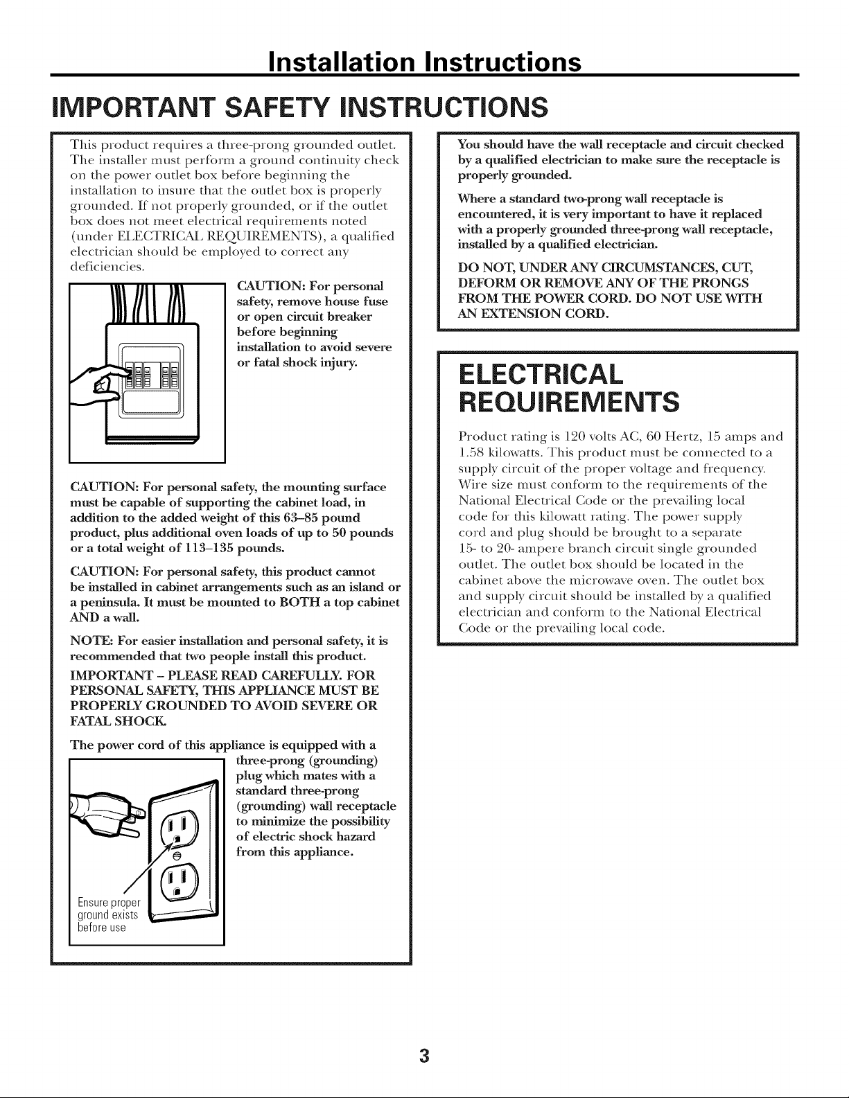
This product requires a three-prong grounded outlet°
The installer must perK_rm a ground continuity check
on the power outlet box befbre beginning the
installation to insure that the out|et box is properly
grounded. If not properly grounded, or if the out|et
box does not meet electrical requirements noted
(under EI,ECTRICAI, REQUIREMENTS), a qualified
electrician should be employed to correct any
deficiencies.
CAUTION: For personal
safety, remove house fuse
or open circuit breaker
before beginning
installation to avoid severe
or fatal shock injury.
w
CAUTION: For personal safety, the mounting surface
must be capable of supporting the cabinet load, in
addition to the added weight of this 63-85 pound
product, plus additional oven loads of up to 50 pounds
or a total weight of 113-135 pounds.
CAUTION: For personal safety, this product cannot
be installed in cabinet arrangements such as an island or
a peninsula. It must be mounted to BOTH a top cabinet
AND a wall.
NOTE: For easier installation and personal safety, it is
recommended that two people install this product.
IMPORTANT - PLEASE READ CAREFULLY. FOR
PERSONAL SAFETY, THIS APPLIANCE MUST BE
PROPERLY GROUNDED TO AVOID SEVERE OR
FATAL SHOCK.
You should have the wall receptacle and circuit checked
by a qualified electrician to make sure the receptacle is
properly grounded.
Where a standard two-prong wall receptacle is
encountered, it is very important to have it replaced
with a properly grounded three-prong wall receptacle,
installed by a qualified electridan.
DO NOT, UNDER ANY CIRCUMSTANCES, CUT,
DEFORM OR REMOVE ANY OF THE PRONGS
FROM THE POWER CORD. DO NOT USE WITH
AN EXTENSION CORD.
ELECTRICAL
REQUIREMENTS
Product radng is 120 volts AC, 60 Hertz, 15 amps and
1.58 ldlowatts. This product must be connected to a
supply circuit of the proper voltage and flequency:
Wire size lllust conf_)IIIl to the requirements of the
National Electrical Code or the prevailing local
code for this Mlowatt rating. The power supply
cord and plug should be brought to a separate
15- to 20- ampere branch circuit single grounded
outlet. The outlet box should be located in the
cabinet above the microwave oven. The outlet box
and supply circuit should be installed by a qualified
electrician and confbrm to the National Electrical
Code or the prevailing local code.
The power cord of this appliance is equipped with a
three-prong (grounding)
plug which mates with a
standard three-prong
(grounding) wall receptacle
to minimize the possibility
of electric shock hazard
from this appfiance.
Ensure proper
ground exists
before use
3
Page 4
Installation Instructions
HOOD EXHAUST
NOTE: Read these next two pages only if you plan to vent your exhaust to the
outside. If you plan to recirculate the air back into the room, proceed to page 6.
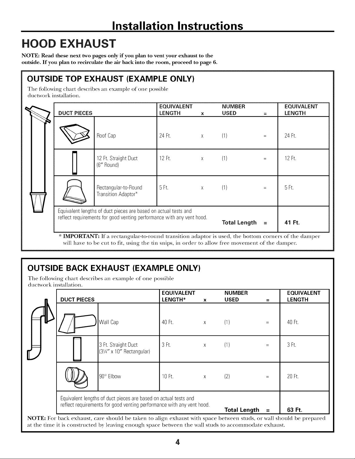
OUTSIDE TOP EXHAUST (EXAMPLE ONLY)
The following chart describes an example of one possible
ductwork installation.
EQUIVALENT NUMBER EQUIVALENT
DUCT PIECES LENGTH x USED = LENGTH
24Ft. x (1)
12Ft.StraightDuct
RoofCap
(6"Round)
TransitionAdaptod
Rectangular-to-Round
Equivalentlengthsof ductpiecesarebasedonactualtests and
reflectrequirementsfor goodventingperformancewith anyventhood.
* IMPORTANT: If a rectangular-to-round uansition adaptor is used, the bottom corners of the damper
will have to be cut to fit, using the fin snips, in order to allow flee movement of the dampeL
12Ft. x (1)
5 Ft. x (1) =
OUTSIDE BACK EXHAUST (EXAMPLE ONLY)
The following chart describes an example of one possible
ductwork installation.
EQUIVALENT
DUCT PIECES
LENGTH* x
24Ft.
12Ft.
5 Ft.
Total Length = 41 Ft.
NUMBER
USED
EQUIVALENT
LENGTH
Wall Cap
3 Ft.StraightDuct
31A"x 10" Rectangular)
(_ 90° Elbow 10Ft. x (2) = 20Ft.
Equivalentlengthsof ductpiecesarebasedonactualtestsand
reflectrequirementsforgoodventingperformancewith anyvent hood.
NOTE: For back exhaust, care should be taken to align exhaust with space between studs, or wall should be prepared
at the time it is constructed by leaving enough space between the wall studs to accommodate exhaust.
40Ft.
3 Ft.
(1)
(1)
Total Length = 63 Ft.
40Ft.
3 Ft.
4
Page 5
Installation Instructions
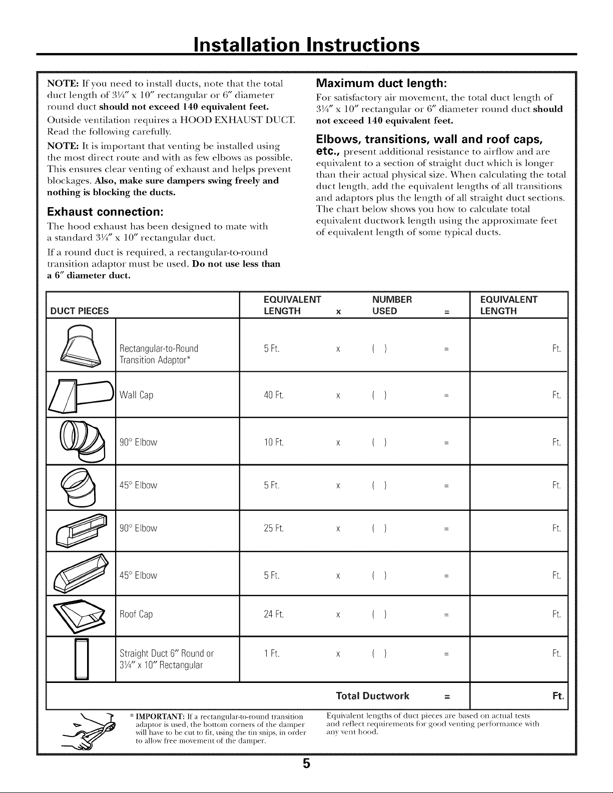
NOTE: If you need to install ducts, note that the total
duct length of 3¼"x 10" rectangular or 6" diameter
round duct should not exceed 140 equivalent feet.
Outside ventilation requires a HOOD EXHAUST DUCT.
Read the following careflflly.
NOTE: It is important that venting be installed using
the most direct route and with as few elbows as possible.
This ensures clear venting of exhaust and helps prevent
blockages. Mso, make sure dampers swing freely and
nothing is blocking the ducts.
Exhaust connection:
The hood exhaust has been designed to mate with
a standard 3¼" x 10" rectangular duct.
If a round duct is required, a rectangular-to-round
uansition adaptor must be used. Do not use less than
a 6" diameter duct.
EQUIVALENT
DUCT PIECES
Rectangular-to-Round
TransitionAdapto¢
LENGTH
5Ft.
Maximum duct length:
For satisfactory air movement, the total duct length of
3¼"x 10" rectangular or 6" diameter round duct should
not exceed 140 equivalent feet.
Elbows, transitions, wall and roof caps,
etc., present additional resistance to airflow and are
equivalent to a section of suaight duct which is longer
than their actual physical size. When calculating the total
duct length, add the equivalent lengths of all uansifions
and adaptors plus the length of all suaight duct sections.
The chart below shows you how to calculate total
equivalent ductwork length using the approximate feet
of equivalent length of some typical ducts.
NUMBER
x USED
x ( )
= LENGTH
=
EQUIVALENT
Ft.
%
G
O
O
Wall Cap
%0 Elbow
45° Elbow
%0 Elbow
45° Elbow
RoofCap
StraightDuct6" Roundor
31/4"x 10" Rectangular
40 Ft.
10 Ft.
5Ft.
25 Ft.
5Ft.
24Ft.
1Ft.
x ( )
x ( )
x ( )
x ( )
x ( )
x ( )
x ( )
=
=
=
=
=
=
=
Ft.
Ft.
Ft.
Ft.
Ft.
Ft.
Ft.
* IMPORTANT: If a rectangular-to-round transition
adaptor is used, the bottom corners of the damper
will have to be cut to fit, using the tin snips, in order
to allow ti'ee movement of the damper.
Total Ductw0rk
Equivalent lengths of duct pieces are based on actual tests
and reflect requirenaents tot good venting pertormance with
any vent hood.
==
5
Ft.
Page 6
Installation Instructions
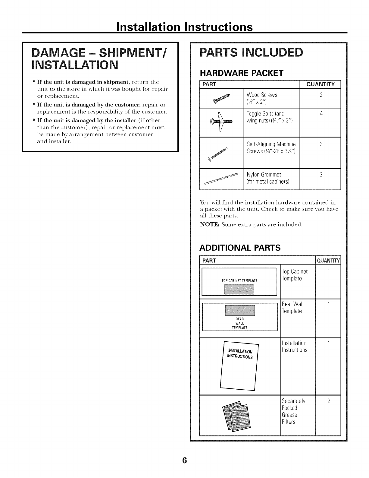
DAMAGE - SHIPMENT/
iNSTALLATiON
, If the unit is damaged in shipment, return the
unit to the store in which it was bought for repair
or replacement.
" If the unit is damaged by the customer, repair or
replacement is the responsibility of the customer
" If the unit is damaged by the installer (if other
than the customer), repair or replacement must
be made by arrangement bet_,veen customer
and installer
PARTS INCLUDED
HARDWARE PACKET
PART
WoodScrews
(¼" x 2")
ToggleBolts(and
wing nuts)(3A6"x3")
Self-AligningMachine
Screws(¼"-28x 3¼")
NylonGrommet
(formetalcabinets)
You will find the installation hardware contained in
a packet with the unit. Gheck to make sure you have
all these parts.
NOTE: Some exua parts are included.
QUANTITY
2
ADDITIONAL PARTS
PART
TOP CABINETTEMPLATE
REAR
WALL
TEMPLATE
INSTRUCTIONS
TopCabinet
Template
RearWall
Template
Installation
Instructions
Separately
Packed
Grease
Filters
QUANTITY
1
6
Page 7

Installation Instructions
TOOLS YOU WILL NEED
# 1and#2 Phillipsscrewdriver
Tinsnips(forcutting
damper,if required)
Gloves
Scissors
(tocuttemplate,if necessary)
Saw(saber,holeor keyhole)
Pencil
Ruleror tapemeasureand
t edge
Electricdrill with s_s',Y2"and%"
drill bits
8
Studfinder er
Hammer (optional)
Carpentersquare
(optional)
Fillerblocksor scrap
woodpieces,if needed
fortop cabinetspacing
(usedonrecessedbottom
cabinetinstallationsonly)
Safety goggles
MOUNTING SPACE
66" or More
fromthe Floor
tothe Topof
the Microwave
BottomEdgeof
CabinetNeedsto
be30" or More
from the Cooking
Backsplash
Surface
Level
NOTES:
• The space between the cabinets must be
• 0 wide and free of obstructions.
• If the space between the cabinets is greater
than 30", a Fillet Panel Kit may be used to fill
in the gap between the microwave oven and
the cabinets. Your Owner's Manual contains
the kit number for your model.
• This microwave oven is for installation over
ranges tap to 36" wide.
• If you are going to vent your microwave oven
to the outside, see Hood Exhaust Section for
exhaust duct preparation.
• When installing the microwave oven beneath
smooth, flat cabinets, be careful to follow the
instructions on the top cabinet template for
power cord clearance.
Duct and masking tape
\
7
Page 8
Installation Instructions
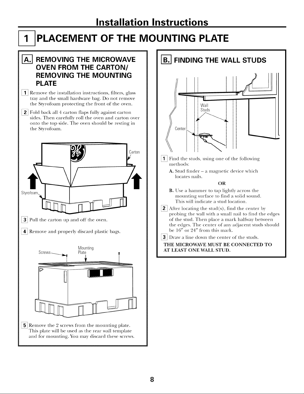
[ PLACEMENT OF THE MOUNTING PLATE
REMOVING THE MICROWAVE
OVEN FROM THE CARTON/
REMOVING THE MOUNTING
PLATE
_ Remove the installation instructions, filters, glass
tray and the small hardware bag. Do not remove
the Styrofoam protecting the front of the oven.
[] Fold back all 4 carton flaps fully against carton
sides. Then careflflly roll the oven and carton over
onto the top side. The oven should be resting in
the Styrofoam.
[]Pull the carton tap and off the oven.
[] Remove and properly discard plastic bags.
Mounting
Plate
I-_ FINDING THE WALL STUDS
Wall
= Studs
_!_ Find the studs, using one of the following
methods:
A. Stud finder - a magnetic device which
locates nails.
OR
B. Use a hammer to mp lighdy across the
mounting surfi_ce to find a solid sound.
This will indicate a sam loca6on.
After locating the stud(s), find the center by
probing the wall with a small nail to find the edges
of the stud. Then place a mark half\,vay between
the edges. The center of any adjacent sums should
be 16" or 24" flom this mark.
_Draw a line down the center of the studs.
THE MICROWAVE MUST BE CONNECTED TO
AT LEAST ONE WALL STUD.
[]Remove the 2 screws fiom the mounting plate.
This plate will be used as the rear wall template
and for mounting. You may discard these screws.
8
Page 9
Installation Instructions
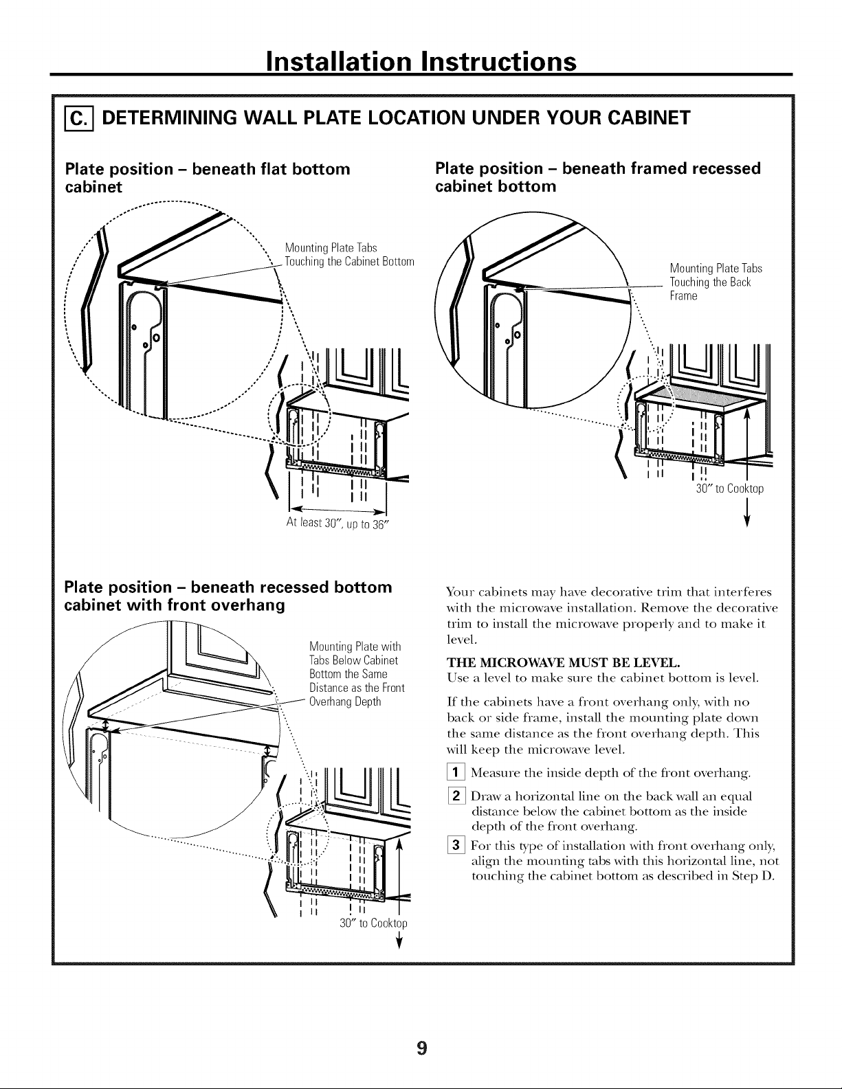
DETERMINING WALL PLATE LOCATION UNDER YOUR CABINET
Plate position - beneath flat bottom
cabinet
MountingPlateTabs
o°
",,%
%.
At least 30", up to 36"
the CabinetBottom
Plate position - beneath framed recessed
cabinet bottom
MountingPlateTabs
Touchingthe Back
Frame
I1
30" to Cooktop
Plate position - beneath recessed bottom
cabinet with front overhang
MountingPlatewith
TabsBelowCabinet
BottomtheSame
Distanceas the Front
OverhangDepth
i II
i II
30" to Cooktop
÷
Your cabinets may have decorative trim that interferes
with the microwave installation. Remove the decorative
trim to install the microwave properly and to make it
level.
THE MICROWAVE MUST BE LEVEL.
Use a level to make sure the cabinet bottom is level.
If the cabinets have a flont overhang only, with no
back or side flame, install the mounting plate down
the same distance as the flont overhang depth. This
will
keep the microwave level.
[]
Measure the inside depth of the flont overhang.
%
Draw a horizontal line on file back wall an equal
distance below the cabinet bottom as the inside
depth of the flont overhang.
%
For this type of installation with flont overhang only,
align the mounting robs with tiffs horizontal line, not
touching the c_fl)inet bottom as described in Step D.
9
Page 10
Installation Instructions
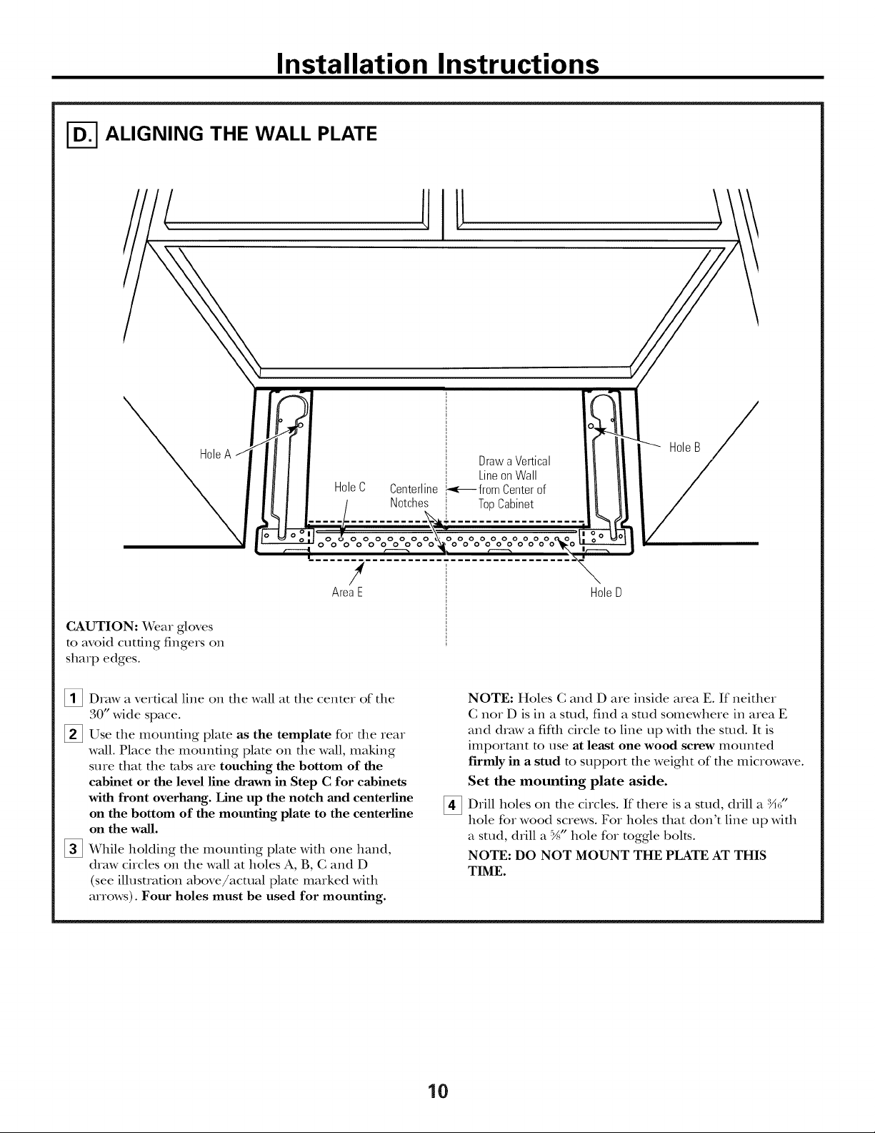
ALIGNING THE WALL PLATE
HoleC Centerline
Notches
HoleB
Drawa Vertical
LineonWall
'.<-_ from Centerof
TopCabinet
0000000
000000000
!
AreaE HoleD
CAUTION: Wear gloves
to avoid cutting fingers on
sharp edges.
[]Draw a vertical line on file wall at the center of the
30" wide space.
[]Use the mounting plate as the template for the rear
waU. Place the mounting plate on tim waU, making
sure that the tabs are touching the bottom of the
cabinet or the level line drawn in Step C for cabinets
with front overhang. Line up the notch and centerline
on the bottom of the mounting plate to the centerline
on the wall.
[] While holding the mounting plate with one hand,
draw circles on the wall at holes A, B, C and D
(see illusuation above/acatal plato marked with
arrows). Four holes must be used for mounting.
NOTE: Holes C and D are inside area E. If neither
C nor D is in a sutd, find a sutd somewhere in area E
and draw a fifth circle to line lap with the stud. It is
important m use at least one wood screw mounted
firmly in a stud m support the weight of the microwave.
Set the mounting plate aside.
Drill holes on the circles. If there is a stud, drill a X_/'
[]
hole for wood screws. For holes that don't line up with
a sutd, drill a %" hole for toggle bolts.
NOTE: DO NOT MOUNT THE PLATE AT THIS
TIME.
10
Page 11
Installation Instructions
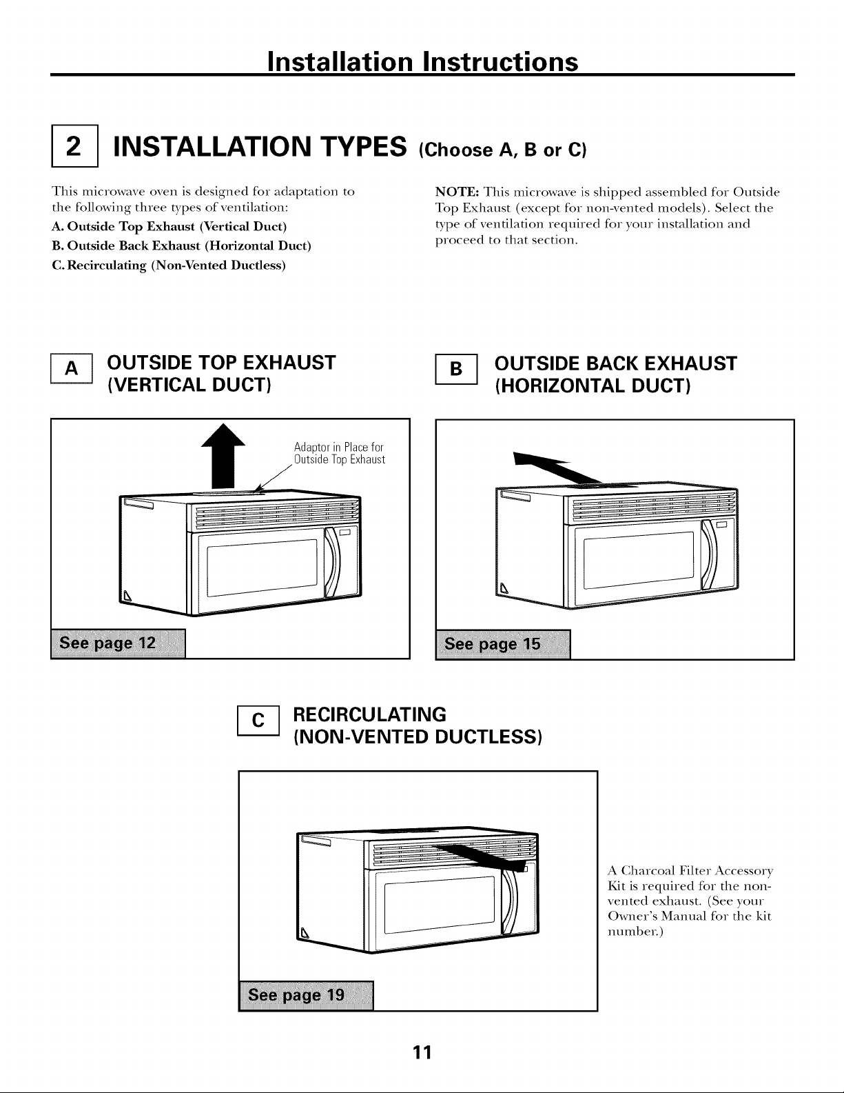
INSTALLATION TYPES
This microwave oven is designed for adaptation to
the following three types of ventilation:
A. Outside Top Exhaust (Vertical Duct)
B. Outside Back Exhaust (Horizontal Duct)
C. Recirculating (Non-Vented Ductless)
OUTSIDE TOP EXHAUST
(VERTICAL DUCT)
Adaptorin Placefor
/
OutsideTopExhaust
(Choose A, B or C)
NOTE: This microwave is shipped assembled for Outside
Top Exhaust (except for non-vented models). Select the
type of ventilation required for your installation and
proceed to that section.
OUTSIDE BACK EXHAUST
(HORIZONTAL DUCT)
RECIRCULATING
(NON-VENTED DUCTLESS)
11
A Gharcoal Filter Accessory
Kit is required for the non-
vented exhaust. (See your
Owner's Manual for the kit
ntltllbeI:)
Page 12
Installation Instructions
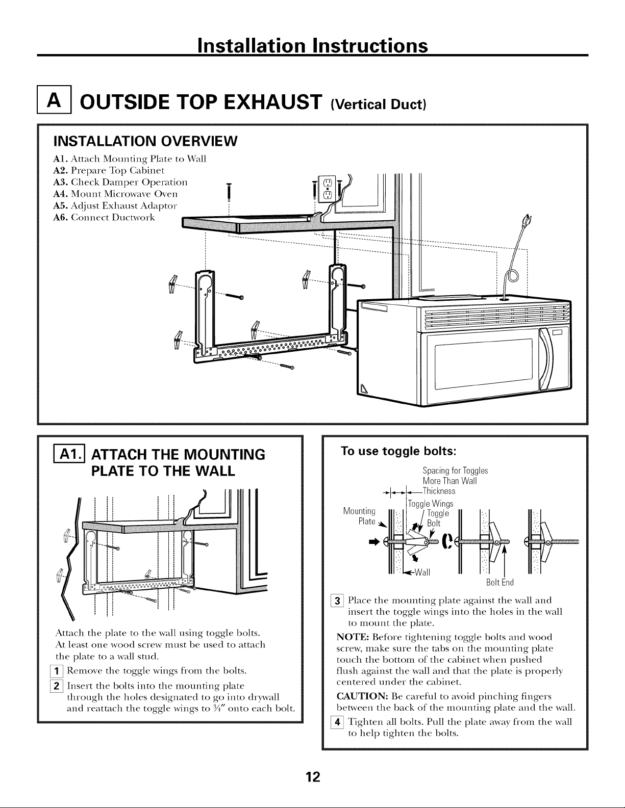
OUTSIDE TOP EXHAUST (Vertical Duct)
INSTALLATION OVERVIEW
A1. Attach Mounting Plate to Wall
A2. Piepa_e Top Cabinet
A3. Check Dampe_ Opeiation
A4. Mount Mic_owave Oven
A5. Adjust Exhaust Adaptor
A6. Connect Ductwo_k
|
I
I
I-_ ATTACH THE MOUNTING
PLATE TO THE WALL
Attach the plate to the wall using toggle bolts.
At least one wood sciew illust be used to attach
the plate to a wall stud.
[]Remove the toggle wings flom the bolts.
[] Inse_t the bolts into the moundng plate
th_ough the holes designated to go into d_)_,vall
and _eatmch the toggle wings to :_" onto each bolt.
===m
To use toggle bolts:
Spacingfor Toggles
MoreThanWall
+l_,.[_,_Th ickness
Mounting
Plate_.
_ Place the mounting plate against the wall and
inse_t the toggle wings into the holes in the wall
to mount the plate.
NOTE: Befo_e tightening toggle bolts and wood
sc_ew, make sme the robs on the mounting plate
touch the bottom of the cabinet when pushed
flush against the wall and that the plate is p_ope_ly
cente_ed under the cabinet.
CAUTION: Be ca_eflll to avoid pinching fingeis
between the back of the mounting plate and the wall.
_ Tighten all bolts. Pull the plate away fiom the wall
to help tighten the bolts.
ToggleWings
BoltEnd
12
Page 13
Installation Instructions
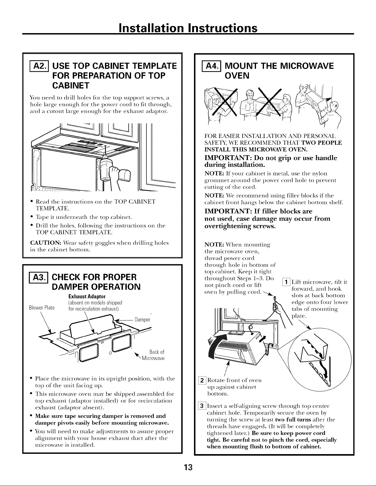
1-_ USE TOP CABINET TEMPLATE
FOR PREPARATION OF TOP
CABINET
You need to drill holes for tile top support screws, a
hole large enough for tile power cord to fit ttlrough,
and a cutout large enough for tile exllaust adaptoL
• Read the instructions on the TOP CABINET
TEMPI ,ATE.
• Tape it underneattl tile top cabinet.
• Drill tile holes, following tile instructions on tile
TOP CABINET TEMPI,ATE.
CAUTION: Wear safety goggles when drilling holes
in tile cabinet bottom.
I-_ CHECK FOR PROPER
DAMPER OPERATION
ExhaustAdaptor
BlowerPlate
(absentonmodelsshipped
for recirculationexhaust)
Damper
I-_ MOUNT THE MICROWAVE
OVEN
FOR EASIER INSTAI,I,ATION AND PERSONAI,
SAFETY, WE RECOMMEND THAT TWO PEOPLE
INSTALL THIS MICROWAVE OVEN.
IMPORTANT: Do not grip or use handle
during installation.
NOTE: If your cabinet is metal, use tim nylon
grommet around tim power cord hole to prevent
cutting of tim cord.
NOTE: We recommend using filler blocks if the
cabinet flont hangs below the cabinet bottom shelf.
IMPORTANT: If filler blocks are
not used, case damage may occur from
overtightening screws.
NOTE: When mounting
tile microwave oven,
thread power cord
through hole in bottom of
top cabinet. Keep it tight
throughout Steps 1-3. Do
not pinch cord or lift
oven by pulling cord.
_I,ifl tilt it
microwave,
forward, and hook
slots at back bottom
edge onto four lower
robs of mounting
Backof
Microwave
• Place tile microwave in its upright position, with the
top of tim unit facing up.
• This microwave oven may be shipped assembled for
top exhaust (adaptor installed) or for recirculadon
exhaust (adaptor absent).
• Make sure tape securing damper is removed and
damper pivots easily before mounting microwave.
• You will need to make adjusmlents to assure proper
alignment with your house exhaust duct after the
microwave is installed.
_ Rotate flont of
up against cabinet
bottom.
oven
_Insert a self-aligning screw through top center
cabinet hole. Temporarily secure the oven by
turning the screw at least two full turns after the
threads have engaged. (It will be completely
tightened later.) Be sure to keep power cord
tight. Be careful not to pinch the cord, especially
when mounting flush to bottom of cabinet.
13
Page 14
Installation Instructions
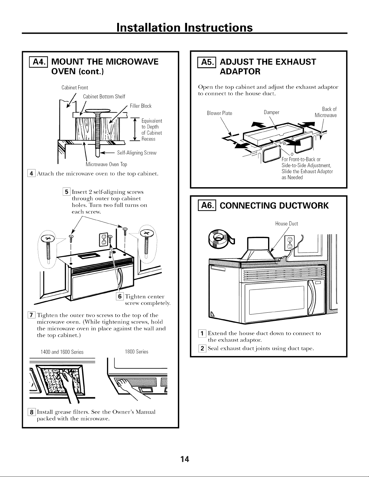
I-_ MOUNT THE MICROWAVE
OVEN (cont.)
CabinetFront
CabinetBottomShelf
FillerBlock
to Depth
ofCabinet
-i--Equivalent
Recess
Self-AligningScrew
MicrowaveOvenTop
[]Attach the microwave oven to the top cabinet°
[] Insert 2 self-aligning screws
through outer top cabinet
holes. Turn two flfll [tlIns on
each screw.
ADJUST THE EXHAUST
ADAPTOR
Open the top cabinet and adjust the exhaust adaptor
to connect to the house duct.
Backof
BlowerPlate Damper Microwave
Side-to-Side Adjustment,
Slidethe ExhaustAdaptor
asNeeded
I-_ CONNECTING DUCTWORK
HouseDuct
I
[]Tighten center
screw completely.
[] Tighten the outer two screws to the top of the
microwave oven. (While tightening screws, hold
the microwave oven in place against the wall and
the top cabinet.)
1400and1600Series 1800Series
_;__4
_ Install grease filters. See the Owner's Manual
packed with the microwave.
_1_ Extend the house duct down to connect to
the exhaust adaptor.
Seal exhaust duct joints using duct tape.
14
Page 15
Installation Instructions
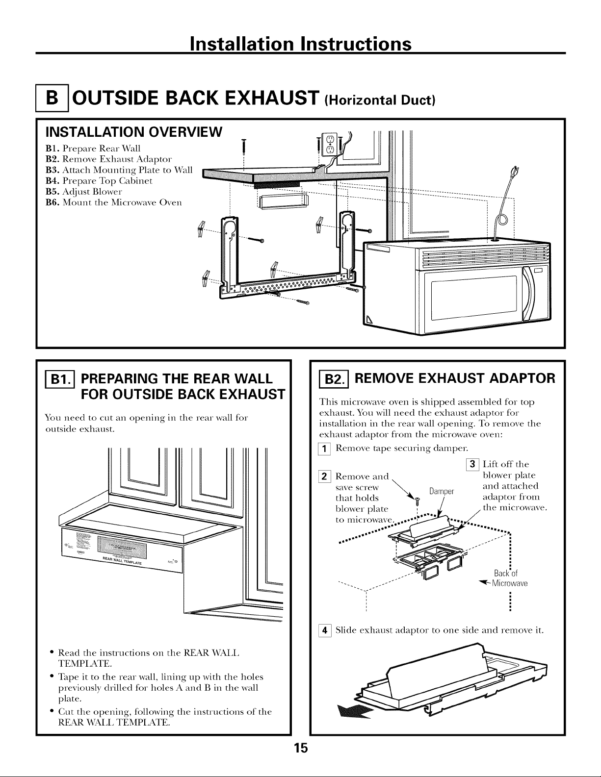
OUTSIDE BACK EXHAUST (Horizontal Duct)
INSTALLATION OVERVIEW
B1. Prepare Rear Wall
B2. Remove Exhaust Adaptor
B3. Attach Mounting Plate to Wall
B4. Prepare Top Cabinet
BS. Adjust Blower
B6. Mount the Microwave Oven
|
I-_ PREPARING THE REAR WALL
FOR OUTSIDE BACK EXHAUST
You need to cut an opening in the rear wall for
outside exhaust.
I-_ REMOVE EXHAUST ADAPTOR
This microwave oven is shipped assembled for top
exhaust. You will need the exhaust adaptor for
installation in the rear wall opening. To remove the
exhaust adaptor from the microwave oven:
Remove rope securing dampm.
Lift off the
Remove and blower plate
save screw _ _ and attached
• " uamper
that holds "_, / adaptor fiom
blower plate ;..._/, / the microwave.
to microwave; ..... _,,_,.,,
......... i...."..
• Read the insuucfions on the REAR X_SkLL
TEMPIATE.
• Tape it to the rear wall, lining tap with the holes
previously drilled for holes A and B in the wall
plate.
• Gut the opening, following the instructions of the
REAR X_SkLLTEMPLATE.
°" i
..... -..... Microwave
_ Slide exhaust adaptor to one side and remove it.
15
_ Backof
Page 16

Installation Instructions
| ATTACH THE MOUNTING
IL,==========,_
PLATE TO THE WALL
!
Attach the plate to the wall using toggle bolts.
At least one wood screw must be used to attach
the plate to a wall stud.
[] Remove the toggle wings flom the bolts.
[]Insert the bolts into the mounting plate through
the holes designated to go into drywall and reatmch
the toggle wings to :5" onto each bolt.
To use toggle bolts:
SpacingforTogglesMore
-.-I+---i+,,--ThanWallThickness
I
Mounting
Plate
,,I,
iToggle Wings
<-Wall "_
q
USE TOP CABINET TEMPLATE
FOR PREPARATION OF TOP
CABINET
You need to drill holes for the top support screws and
a hole large enough for the power cord to fit through.
• Read the insuuctions on the TOP (;ABINET
TEMPI ,ATE.
• Tape it underneath the top cabinet.
• Drill the holes, following the instructions on the
TOP CABINET TEMPIATE.
CAUTION: Wear safety goggles when drilling holes
in the cabinet bottom.
I-_ ADAPTING MICROWAVE
BLOWER FOR OUTSIDE
BACK EXHAUST
BoltEnd
[]Place the mounting plate against the wall and
insert the toggle wings into the holes in the wall
to mount the plate.
NOTE: Before tightening toggle bolts and wood
screw, make sure the robs on the mounting plate
touch the bottom of the cabinet when pushed flush
against the wall and that the plate is properly
centered under the cabinet.
CAUTION: Be careflfl to avoid pinching fingers
between the back of the mounting plate and the wall.
[]Tighten all bolts. Pull the plate away from the wall
to help dghten the bolts.
_ Remove and that holds blower motor
to microwave.
[] Gareflflly the blower unit. The wirespull
will extend far enough to allow you to adjust the
blower unit.
EndA
save sciew
BlowerMotor
"_/f!.-- BlowerMotor
- "_'- Screw
otlt
16
EndB
Page 17

Installation Instructions
ADAPTING MICROWAVE
BLOWER FOR OUTSIDE
BACK EXHAUST (cont.)
[] Rotate blower unit counterclockwise 180 °.
BeforeRotation After Rotation
Microwave Microwave
_l_ Gently the wires flom the
Reroute the wires through grooves on other side
of the blower unit.
ielilove
BeforeRerouting After Rerouting
giooves.
[]Place the blower unit back into the opening.
EndA
End
CAUTION: Do not pull or stretch the blower
unit wiring. Make sure the wires are not
pinched.
NOTE: The blower unit exhaust
openings should match exhaust
openings on rear of microwave oven.
[] Secure the blower unit to the microwave with
the screw from Step l.
BlowerPlate
1
I
Backof
Microwave
WiresRoutedThroughRightSide Wires RoutedThroughLeftSide
[]Roll the blower unit 90 ° so that fan blade
openings are facing out the back of the
illicrowave.
BeforeRolling
Backof
Microwave
After Rolling
_ Backof
Microwave
BlowerMotor
Screw
[]Replace the blower in theplate position
as before with the screw.
[]Attach the exhaust the of theadaptor
oven by sliding it into the guides at the top
center of the back of the oven.
Adaptor
Guide
_ LockingTabs
same
to rear
Backof
Microwave
_r_. Guide
17
Push in securely until it is in the lower locking
robs. Take care to assure that the damper hinge
is installed so that it is at the top and that the
damper swings freely.
Page 18

Installation Instructions
I-_ MOUNT THE MICROWAVE
OVEN
;TJ J
FOR EASIER INSTAI,I,ATION AND PERSONAL
SAFETY, WE RECOMMEND THAT TWO PEOPLE
INSTALL THIS MICROWAVE OVEN.
IMPORTANT: Do not grip or use handle
during installation.
NOTE: If your cabinet is metal, use tim nylon
grommet around the power cord hole to prevent
cutting of the cord.
NOTE: We recommend using fillet blocks if the
cabinet flont hangs below the cabinet bottom shelf.
IMPORTANT: If filler blocks are
not used, ease damage may occur from
overtightening screws.
CabinetFront
CabinetBottomShelf
FillerBlock
T quivalent
to Depth
ofCabinet
Recess
Self-AligningScrew
MicrowaveOvenTop
_ Attach the microwave oven to the top cabinet.
Insert 2 self-aligning screws
through outer top cabinet
holes. Turn two fltll turns on
each screw.
NOTE: When mounting
the Illicrowave oven,
thread power cord
through hole in bottom of
top cabinet. Keep it tight
throughout Steps 1-3. Do
not pinch cord or lift
oven by pulling cord.
[]Lift microwave, tilt it
forward, and hook
slots at back bottom
edge onto four lower
tabs of mounting
plate.
J
[]Rotate fiont of
up against cabinet
bottom.
_Insert a self-aligning screw through top center
cabinet hole. Temporarily secure the oven by
turning the screw at least two full turns after the
threads have engaged. (It will be completely
6ghtened later.) Be sure to keep power cord
tight. Be careful not to pinch the cord, espedally
when mounting flush to bottom of cabinet.
oven
_ Tighten center
screw completely.
[] Tighten the outer two screws to the top of the
microwave oven. (While tightening screws, hold
the microwave oven in place against the wall and
the top cabinet.'
1400and1600Series
_ Install grease filters. See the Owner's Manual
packed with the microwave.
1800Series
18
Page 19

Installation Instructions
RECIRCULATING
INSTALLATION OVERVIEW
C1. Attach Mounting Plate to Wall
C2. Prepare Top Cabinet
C3. Check Microwave Assembly
C4. Adjust Blower
C5. Mount the Microwave Oven
C6. Install Charcoal Filter
I-_ ATTACH THE MOUNTING
PLATE TO THE WALL
, I
(Non-Vented Ductless}
_ Place the mounting plate against the wall and
insert the toggle wings into the holes in the wall
to I_lount the plate.
NOTE: Before tightening toggle bolts and wood
screw, make sure the robs on the mounting plate
touch the bottom of the cabinet when pushed flush
against the wall and that the plate is properly
cente_ed under the cabinet.
CAUTION: Be careflll to avoid pinching fingers
bet\,veen the back of the mounting plate and the wall.
_ Tighten all bolts. Pull the plate away flom the wall
to help tighten the bolts.
\
Attach the plate to the wall using toggle bolts.
At least one wood screw illust be used to attach
the plate to a wall stud.
[]Remove the toggle wings flom the bolts.
[]Insert the bolts into the mounting plate through
the boles designated to go into dr)_vall and
reatmch the toggle wings to :_A"onto each bolt.
To use toggle bolts:
Spacingfor Toggles
MoreThanWall
-_l_.i_---Thickness
Mounting
Plate
ToggleWings
BoltEnd
USE TOP CABINET TEMPLATE
FOR PREPARATION OF TOP
CABINET
You need to ohill holes foi the top suppoit sciews and
a hole large enough for the power cord to fit through.
• Read the instructions on the TOP GABINET
TEMPI_ATE.
• Tape it tmdemeath the top cabinet.
• Drill the holes, following the instructions on the
TOP CABINET TEMPLATE.
CAUTION: Wear safeb, goggles when drilling holes
in the cabinet bottom.
19
Page 20

Installation Instructions
CHECK MICROWAVE ASSEMBLY
Exhaust Adaptor (absent
on models shipped for
recirculation exhaust)
Backof
,,
• Place the microwave in its upright position, with the
top of the unit facing up.
• The microwave oven may be shipped assembled for
top exhaust (adaptor installed) or for recirculation
exhaust (adaptor absent).
• If the microwave was shipped for recirculafion
exhaust, skip to (;5. If shipped for top exhaust,
proceed with (;4.
ADAPTING MICROWAVE
BLOWER FOR RECIRCULATION
_ Careflflly pull out the blower unit. The wires
will extend far enough to allow you to adjust the
blower unit.
_Roll the blower unit 90 ° so that fan blade openings
are facing toward the flont of the microwave.
[] Remove . _ Denper [] I,ifl off the
and save , blower plate
screw that and attached
holds blower" adaptor from
plate to the microwave.
microwave. [
Backof
_-- Microwave "
_ Slide exhaust adaptor to one side and remove it.
NOTE: The exhaust adaptor with damper is not
needed for recirculating models. You may want to
save them for possible furore use.
_ Remove and the that holds the blower
motor to the microwave.
_ BlowerPlate
save screw
R011
NOTE: Make sure wires remain routed in the
grooves of the motor flame.
_11_ Backof
€_ _- Microwave
11_ "----. _. BlowerMotor
""q_-- Screw
20
Page 21

Installation Instructions
ADAPTING MICROWAVE
BLOWER FOR
RECIRCULATION (cont.)
]Place tile blower unit back into tile opening.
CAUTION: Do not pull or stretch the blower unit
wiring, Make sure the wires are not pinched,
]Secure blower unit to microwave with the screw
removed in Step 4.
[]Replace blower plate with the screw removed in
Step l.
T
i
_.___ Backof
Microwave
NOTE: When mounting
tile microwave oven,
thread power cord
through hole in bottom of
top cabinet. Keep it fight
throughout Steps 1-3. Do
not pinch cord or lift
oven by pulling cord.
_ Rotate flont of oven
up against cabinet
bottom.
[]Lift microwave, tilt it
forward, and hook
slots at back bottom
edge onto four lower
tabs of mounting
)late.
_ Insert a self-aligning screw through top center
cabinet hole. Temporarily secure the oven by
turning the screw at least two full turns after the
threads have engaged. (It will be completely
6ghtened later.) Be sure to keep power cord
tight. Be careful not to pinch the cord, especially
when mounting flush to bottom of cabinet.
I-_ MOUNT THE MICROWAVE
OVEN
FOR EASIER INSTAI,I,ATION AND PERSONAL
SAFETY, WE RECOMMEND THAT TWO PEOPLE
INSTALL THIS MICROWAVE OVEN.
IMPORTANT: Do not grip or use handle
during installation.
NOTE: If your cabinet is metal, use the nylon
grommet around the power cord hole to prevent
cutting of the cord.
NOTE: We recommend using fillet blocks if the
cabinet flont hangs below the cabinet bottom shelf.
IMPORTANT: If filler blocks are not used,
case damage may occur from overtightening
screws.
CabinetFront
CabinetBottomShelf
FillerBlock
-3_oEquivalentto Depth
f CabinetRecess
Self-AligningScrew
MicrowaveOvenTop
_Attach the microwave oven to the top cabinet.
21
Page 22

Installation Instructions
MOUNT THE MICROWAVE
OVEN (cont.)
[] Insert 2 self-aligning screws
through outer top cabinet
holes. Turn two flfll turns oil
each screw.
[] Tighten center
screw completely.
[] Tighten tile outer two screws to tile top of tile
microwave oven. (While tightening screws, hold
tile microwave oven in place against tile wall and
tile top cabinet.'
iNSTALLiNG THE
CHARCOAL FILTER
On 1400 and 1600 Series models, remove screws
on flont of grille using a #1 Phillips screwdriveL
On 1800 Series models, remove screws on top
front of grille using a #2 Phillips screwdriver.
Open tile door.
Remove tile grille.
%
On 1400 and 1600 Series models, pull tile grille
suaight off:
On 1800 Series models, slide tile grille to tile left
and pull it suaight off.
Charcoal
1400and1600Series
[] Install grease filters. See tile Owner's Manual
packed with tile microwave.
1800Series
_!_ Install the charcoal filtex. When propmly installed,
tile wire mesh of the filter should be visible from
the f}ont.
Replace the grille and the screws.
_ Close the door.
I
Insert mesh-side up
22
Page 23

Installation Instructions
BEFORE YOU USE YOUR MICROWAVE
-i'7"] Make sure the microwave oven has been
installed according to instructions.
'-_] Remove all packing material flom the
microwave oven.
'_ Install turntable and ring in cavity.
I
I
'_] Read the Owner's Manual.
KEEP INSTALIATION INSTRUCTIONS
FOR THE LOCAL INSPECTOR'S USE.
'-4"7] Replace house fuse or turn breaker back on.
Plug power cord into a dedicated 15- to 20-amp
%
electrical outlet.
F
t
Ensure proper
ground exists /
before use
F
k.
23
Page 24

t 164D3370P20849-40247 ]
01-02 JR Printed in Korea
Page 25

Instrucciones
Homo microondas para
de instalacion
gPreguntas? Llame 800.GE.CARES(800.432.2737)ovi_it_,,_m, p_,_, _. la_-_d_.: GEAppliances.com ]
colocar encima de la estufa
ANTES DE EMPEZAR
Lea estas instrucciones completa y cuidadosamente.
• IMPORTANTE - c;._(leesters
instrucciones para el uso del inspector local.
• IMPORTANTE - C.mpl_,co.
todos los cddigos y ordenanzas gubernamentales.
• Nota para el instalador - Asegfirese de dejar
estas instrucciones con el consumidoL
• Nota para el consumidor - Guarde estas
insuucciones para flmlra referencia.
• Nivel de destrezas - I,a insmlacidn de este aparato
requiere de destrezas b_isicas de mec_inica y electricidad.
• La instalacidn apropiada es responsabilidad
del instalador.
• La falla del producto debido a una insmlacidn
inapropiada no estfi cubierta pot la garan6a.
/
/
/
/
LEA CUlDADOSAMENTE.
GUARDE ESTAS INSTRUCCIONES.
Page 26

Instrucciones de instalacion
CONTENIDO
Informacion general
Instrucciones de seguridad importantes .................. 3
Requisitos el6ctricos ................................................ 3
Campana de escape .............................................. 4, 5
Dafios - Envio / Instalaci6n .................................... 6
Partes incluidas ........................................................ 6
Herramientas que necesitarfi .................................... 7
Espacio de montaje .................................................. 7
Guia de instalacion paso por paso
C6mo colocar el plato de montaje ...................... 8-10
C6mo remover el plato de mont_je ................ 8
Cdmo encontrar los postes
de viga en la pared ........................................ 8
C6mo determinar la localizaci6n de las
placas de la pared ........................................ 9
Recirculacidn ........................................ 19-22
Cdmo adherir el plato de mont_je
a la pared ............................................ 19
Cdmo preparar el gabinete superior ....19
Inspeccione la ensambladura
del microondas ...................................... 20
Cdmo adaptor el calefactor del
microondas para la recirculacidn .... 20, 21
Cdmo monmr el homo
microondas ...................................... 21, 22
Cdmo insmlar el filtro de carbonilla....22
Antes de comenzar a usar su horno microondas .... 23
C6mo alinear la placa de la pared .............. 10
Tipos de instalaci6n .......................................... 11-22
_ Escape superior .......................
C6mo adherir la placa de mont;{ie
a la pared ............................................ 12
Preparaci6n del gabinete superior. ..... 13
C6mo inspeccionar si la operaci6n
del regulador de fifo es apropiada ...... 13
Cdmo montar el homo
microondas .................................... 13, 14
C0mo ;_jusmr el adapmdor de escape ..14
Cdmo conecmr la red de conductos .... 14
_]_ Escape posterior externo ......................
C6mo preparar la pared posterior
para el escape posterior exterior ........ 15
Cdmo remover el adapmdor de escape .. 15
Cdmo adherir el plato de mont;_je
a la pared ............................................ 16
exterior.
12-14
15-18
Cdmo preparar el gabinete superior....16
Cdmo adaptar el calefactor
del microondas para el escape
exterior posterior. ........................... 16, 17
Cdmo montar el homo microondas .... 18
2
Page 27

Instrucciones de instalacion
INSTRUCCIONES DE SEGURIDAD IIVIPORTANTES
Este producto requiere un tomacorriente el_ctrico
de tres paros conecmdo a fierra. E1 insmlador debe
llevar a cabo tma inspecci6n de confimfidad a fierra
en la c_ia elSctrica antes de comenzar la instalaci6n
para asegurar que la c_ja tomacorriente estli conectada
a tierra de manera apropiada. Si no lo estS, o si el
tomacorriente no cumple con los requisitos el_ctricos
indicados (b_)o la secci6n REQUISITOS
ELI_CTRICOS), se deber_ recurrir a un t_cnico
calificado para corregir cualquier deficiencia.
PRECAUCION: Para
seguridad personal,
remueva el fusible
de la casa o abra el
interruptor de drcuito
antes de comenzar la
instalad6n para evitar
descargas el6ctricas
severas o fatales.
w
PRECAUCION: En pos de la seguridad personal,
la superficie de montaje debe ser capaz de soportar
la carga del gabinete, ademfis del peso adicional
(de 63 a 85 libras) de este producto, mils las cargas
adicionales del horno de hasta 50 libras o un peso
total entre 113 y 135 libras.
PRECAUCION: En pos de la seguridad personal,
este producto no puede set instalado en sistemas de
gabinetes tales como los llamados "islas" o "peninsulas."
Este debe set montado tanto a un gabinete superior
como a una pared.
NOTA: Para una instalad6n mils fficil y en pos de la
seguridad personal, se recomienda que dos personas
instalen este producto.
IMPORTANTE: POR FAVOR, LEA
CUIDADOSAMENTE. EN POS DE LA SEGURIDAD
PERSONAL, ESTE APARATO DEBE SER
CONECTADO A TIERRA APROPIADAMENTE
PARA EVITAR DESCARGAS SEVERAS O FATALES.
E1 cable el6ctrico de este
aparato estfi equlpado con
un enchufe de tres paras
(con conexi6n a fierra),
lo cual requiere que el
mismo encaje con un
tomacorriente para tres
patas (con conexi6n a
tierra) de pared para
Aseg0resede
queexisteuna
conexi6na
tierra apropiada
antesdel uso
minimizar la posibilidad
de descargas el6ctricas.
Deberfi hacer que un t6cnico calificado inspeccione el
tomacorriente de pared y el circuito para asegurarse de
que el tomacorriente est6 conectado a tierra de manera
apropiada.
Donde usted encuentre un tomacorriente estSndar de
dos paras, es muy importante que haga que el mismo se
cambie pot uno de tres paras apropiadamente conectado
a fierra, instalado pot un electricista calificado.
BAJO NINGUNA CIRCUNSTANCIA NO CORTE,
DEFORME O REMUEVA NINGUNA DE I_AS PATAS
DEL CABLE ELI_CTRICOo NO LO USE CON UNA
EXTENSION ELI_CTRICA.
REQUISITOS
f
ELECTRICOS
La clasificaci6n del producto es de 120 ratios CA
(AC), 60 hertz, 15 amperios y 1.58 kilovatios. Este
producto debe estar conectado a un circuito de
smninistro del volt, tie y flecuencia apropiados. E1
tamafio del alambre debe conformarse a los requisitos
del National Electric Code o al c6digo local en efecto
para este fndice de kilovafios. E1 cable el_ctrico de
alimenmci6n y el interruptor deber_n llevarse a un
tomacorriente finico conecmdo a tierra de 15 a
20 amperios. La c_ja del tomacorriente deberg estar
localizada en el gabinete encima del homo. La
caja del tomacorriente debe set insmlada pot un
electricism calificado y debe conformarse al National
Electrical Code o al cddigo local en efecto.
3
Page 28

Instrucciones de instalacion
CAIVIPANA DE ESCAPE
NOTA: Lea las siguientes dos pfiginas solamente si planea ventilar el escape hacia el exterior.
Si por el contrario planea recircular el aire de vuelta hacia el sal6n, continfie en la pfigina 6.
ESCAPE SUPERIOR EXTERNO (EJEMPLO SOLAMENTE)
La siguiente mbla describe un ejemplo de una posible
instalaci6n de red de conductos.
LONGITUD NOMERO LONGITUD
PARTESDEL CONDUCTO
EQUIVALENTE x USADO = EQUIVALENTE
24pies x (1)
Conductorectode 12pies
Tapadeltecho
(redondode6")
derect{inguloa redondo_
Adaptadordetransici0n
LaIongitudde laspartesde losconductosequivalentesest,1basadaen pruebasrealesy reflejanlos
requisitosparaIograrunabuenaventilaci0nconcualquiercampanade escape.
* IMPORTANTE: Si se usa un adaptador de transici6n de rectfingulo a redondo, las esquinas del rondo
del regulador de tiros deberfin cortarse para que encajen, usando las tijeras de corte, para permitir el
moximiento libre del regulador de tiros.
12pies x (1)
5pies x (1)
Longitud total =
ESCAPE POSTERIOR EXTERNO (EJEMPLO SOLAMENTE)
I,a siguiente mbla describe un ejemplo de una posible
instalaci6n de red de conductos.
LONGITUD NUIVIERO
PARTESDELCONDUCTO EQUIVALENTE x USADO =
24pies
12pies
5 pies
41 pies
LONGITUD
EQUIVALENTE
_ Tapade pared 40pies x (1) = 40pies
Conductorectode3 pies 3 pies x (1) = 3pies
(rectangularde31/4"x 10")
Cododeg0° 10pies x (2) = 20pies
LaIongituddelaspartesde losconductosequivalentesest8basadaenpruebasrealesy reflejanlos
requisitosparaIograrunabuenaventilaciOnconcualquiercampanadeescape.
NOTA: Para el escape posterior, se debe tener cuidado al alinear el escape entre los espacios de los postes de riga de
la pared, o la pared deberfa ser preparada en el momento de su construcci6n dejando suficiente espacio entre los postes
de riga de la pared para acomodar el escape.
Longitud total = 63 pies
4
Page 29

Instrucciones de instalacion
NOTka Si usted necesim insmlar conducms, tenga
pendienm que la longriald total del conducm rectangular
de 3¼" x 10" o el conducm redondo de 6" de difimetro
no debe sobrepasar 140 pies equivalentes.
Ia venfilacidn exmrna requiere tm CONDUCTO DE
CAMPANA DE ESCAPE. I,ea lo siguienm cuidadosamenm.
NOTka Es impormnm que la venfilacidn sea instalada
usando la rum mils direcm y con la menor canfidad de
codos posible. Esm asegum la venfilacidn del escape y
ayuda a prevenir bloqueos. Tambi6n, cerddrese de que
el regulador de tiro pende libremente y nada bloquea
los conduetos.
Conexiones de escape:
I;_ campana de escape ha sido disefiada pare enct_jar
con un conducm rectangular de 3¼" x 10" estfindaL
Nun conducm redondo es necesmJo, se debe usar un
adapmdor de transicidn de rectangular a redondo.
No use un eondueto menor de 6" de difimetro.
LONGITUD
PARTES DE CONDUCTO
Adaptadordetransici6nde
rectSnguloa redondo_
EQUlVALENTE
5pies
Longitud maxima del conducto:
Para lograr un movimiento satisfactorio del aire, la
longimd total del conducto rectangular de 3¼" x 10"
o el conducto redondo de 6" de di_imeuo no debe
sobrepasar 140 pies equivalentes.
Los codos, transiciones, paredes y tapas
de techo, etc., presentan resistencia adicional al
flt{jo de aire y son equivalentes a una seccidn de
conducto recto el cual es m_is largo que su tamafio ffsico
real. Cuando calcule la longimd total del conducto,
agregue las longitudes equivalentes de todas las
uansiciones y adaptadores, m_is la longimd de todas
las secciones de conducto rectus. La mbla m_is adelante
muesua cdmo puede calcular la longimd aproximada
de la red de conductos usando pies aproximados de
longitudes equivalentes de algunos conductos tfpicos.
NUMERO
X
USADO
LONGITUD
EQUlVALENTE
pies
%
G
O
O
m
m
Tapadepared
Cododeg0°
Codode45°
Cododeg0°
Codode45°
Tapadetecho
Conductorectode 6" redondo
o rectangularde3V4"x10"
40 pies
10pies
5pies
25pies
5pies
24pies
1pies
pies
pies
pies
pies
pies
pies
pies
Total red de conductos = pies
transici6n de rectfing-ulo a redondo, las esquinas del en pruebas reales y refleian los requisitos para lograr tma buena
tbndo del regulador de tiros deber_in set cortadas "¢eiltilaci_Sn con cualquier campana de escape.
* IMPORTANTF: Si se usa tm adaptador de La longitud de las partes de conductos e( ui;ralentes est5 basada
para que enc;_ien, usando las tijeras de corte, para
permitir el movimiento libre del regulador de tiros.
5
Page 30

Instrucciones de instalacion
DAKIOS - ENViO /
INSTALACION
. Si la unidad se dafia durante el envio, devuelva
la unidad al almac&l donde la adquiri6 para
su reparaci6n o reemplazo.
. Si el diente dafia la unidad, la reparaci6n o el
reemplazo es responsabilidad del cliente.
. Si el instalador dafia la unidad (si no es el cliente),
la reparaci6n o reemplazo se debe hacer pot
medio de un arreglo entre el cliente y el insmlador.
PARTES INCLUIDAS
PAQUETE DE ELEMENTOS
PARTE
Tornillosdemadera
(1A"x2")
Tornillosbasculantes
(ytuercasdemariposa)
(1A"x3")
Tornillosdem_quina
autoalineables
(W'-28x 3W')
Arandelaaislantede
nil@(paragabinetes
met_Slicos)
Usted enconuard los elementos de insmlaci6n en
un paquete junto con la unidad. Inspeccione para
cerciorarse de que fiene todas las partes.
NOTA: Se incluyen algunas partes adicionales.
CANTIDAD
2
PARTES ADICIONALES
PARTE CANTIDAD
1
TOP CABINETTEMPLATE
REAR
WALL
TEMPLATE
INSTRUCTIONS
Plantillapara
el gabinete
superior
Plantillapara
lapared
posterior
Instrucciones
de instalaciOn
Filtrosde
grasa
empacados
porseparado
6
Page 31

Instrucciones de instalacion
HERRAMIENTAS QUE NECESITARA
Destornilladoresdeestrella
#1y#2
Tijeras para cortar lat6n
(para cortar el regulador
de tiro, si es necesario)
Guantes
Gafasdeseguridad
L@iz
Tijeras(paracortarla
plantilla,si esnecesario)
Sierra(desable,agujero,ode
ojodecerradura)
recta y cinta m6trica
Taladroel6ctricocon brocasde
s/l_',lA" y%"
0
Detectorde
postesdeviga e unmartillo(opcional)
Nivel
Escuadrade
carpintero
(opcional)
Bloquesde rellenoo
pedazosdemadera,si son
necesariospararellenarel
gabinete(usadosselamente
enla instalaci6nde
gabinetesapoyados)
Cintadeconductoso
cintaadhesivaprotectora
ESPACIO DE MONTAJE
Protectorpostenor
desalpicaduras
66" o m_s
desdeel
pisohasta
la parte
superiordel
homo
Elextremedel
fondodel gabinete
necesitaestara
30" em_sa partir
de la superficiede
laestufa
NOTAS:
• E1 espacio enue los gabinetes debe sex de 30"
de ancho y debe esmr libre de obsuucciones.
• Si el espacio enue los gabinetes es mayor de
30", un "Filler Panel Kit" podrfa sex necesario
para rellenar las brechas enue el homo y los
gabinetes. Su Manual del Propietario condene
el ndmero de kit para su modelo.
• Este horno microondas es para sex instalado pox
encima de esmfas basra 36" de ancho.
• Si usted se dispone a ventilar su homo
microondas hacia el exteriox; vex la Secci6n de
Gampana de Escape para la preparaci6n del
conducto de escape.
• Cuando se instale el horno microondas debajo
de gabinetes de rondos lisos y pianos, tenga
cuidado de seguir cuidadosamente las
instrucciones en la plantilla del gabinete superior
para el espado de tolerancia del cable el6ctrico.
7
Page 32

Instrucciones de instalacion
[ COMO COLOCAR EL PLATO DE MONTAJE
c0MoREMOVERELHORNO
NRCROONDAS DEL ENIBALAJE /
C0NIO REMOVER EL PLATO
DE MONTAJE
Remueva las instrucciones de instalaci6n, los
filtros, la bandeja de cristal, y la bolsa pequefia
del equipo. No remueva el protector flontal de
espuma de poliesdreno del homo.
Doble tomlmente hacia atrds las cuatro mpas de
cart6n hacia los lados opuestos de la c_ja. Entonces
descubra el homo y el cart6n en la parte superior.
E1 homo deberfa esmr descansando sobre la
espuma de poliesdreno.
Poliestireno
Tire del cart6n hacia arriba y lejos del homo.
Remueva y deseche debidamente las bolsas de
pldstico.
Tornillos
Platode
montaje
C0MO ENCONTRAR LOS
POSTES DE VIGA EN LA PARED
l i
Postesdewgai
enlapared i
i
Ce_t_°i_i
_ Encuentre los usando de lospostes,
m_todos siguientes:
A. Use un detector de postes- un disposidvo
magnifico que localiza clavos.
B. Use un mardllo para golpear ligeramente a
tray's de la superficie de mont_je hasta
enconuar un sonido sdlido. Esto indicarg que
hay un poste de riga en ese lugar.
Despu_s de localizar el poste o los postes de riga,
encuenue el centro mediante el andlisis de la
pared usando un clavo pequefio para darse
cuenta de d6nde est_in los bordes del poste. Luego
coloque una marca en el cenuo de los bordes.
E1 cenuo de cualquier poste adyacente deberd set
enue 16" 6 24" desde esta marca.
Trace una lfnea hacia ab_jo indicando el centro
del poste.
EL HORNO MICROONDAS DEBE CONECTARSE
POR LO MENOS A UN POSTE DE LA PARED.
tlno
O
Remueva los tornillos flonmles de las placas de la
montma. Estas placas serdn utilizadas como la
plantilla trasera en la pared y para monta_. Puede
desechar estos tornillos.
8
Page 33

Instrucciones de instalacion
_-] C01VIO DETERMINAR LA LOCALIZACION DEL PLATO DE MONTAJE
DEBAJO DE SU GABINETE
Posicion del plato - debajo de gabinetes
de fondo piano
°°
o°
"', Lasorejillasdelplatode
_.......-----_, montajetocanelfondo
/ \del gabinete
:\
; \
1
o*
oo
.o
ooo°
III
22'" I
Por Io menos 30", hasta 36"
Posicion del plato - debajo de gabinetes
de fondo apoyado en un marco
Lasorejillasdelplato
demontajetocanel
marcoposterior
11 I
30" hasta la estufa
Posicion del plato - debajo de gabinetes
de fondo apoyado con frente saliente
Platodemontajecon
orejillaspordebajo
delfondodelgabinete
alamismadistancia
quelaprofundidad
'.:.. delsaliente
..
..
II
II
30" hasta la estufa
Sus gabinetes pod,fan tenet maicos de deco_acidn
que intexfie_an con la insmlacidn del homo
microondas. Remueva los maxcos decorafivos pa_a
instalai el homo ap_opiadamente y pa_a hace_ que
quede nivelado.
EL HORNO MICROONDAS DEBE QUEDAR
NIVELADO.
Use un nivel paia cercio_a_se de que el fondo del
gabinete estA nivelado.
Si los gabinetes tienen un saliente fiontal solamente,
sin ma_co posterior o lateral, insmle el plato de
montaje a la misma distancia de la profundidad
del saliente. Este mantend_g el hobno mic_oondas
nivelado.
[] Mida la profimdidad interna del fiente del saliente.
Trace una lfnea horizontal en la pared posteiior a
una dismncia deb_jo del fondo del gabinete igual
a la p_oflmdidad inmma del flenm saliente.
_ Paxa este tipo de insmlacidn con saliente flonml
solamente, alinee las orejillas de mont;_je con la lfnea
hoIizontal, sin toca_ el fondo del gabinete como se
desc_ibi6 en el Paso D.
9
Page 34

Instrucciones de instalacion
c01vio ALINEAR EL PLATO DE MONTAJE SOBRE LA PARED
Trace una linea
AgujeroA
Agujero C
Muescas vertical en la pared
de la linea _ a partir del centro
del centro delgabinete superior
/
AgujeroB
OOOOOO
O OOOOOOO
!
AreaE
PRECAUCION: Use
guantes de protecci(m
para evitar cortaduras
en sus dedos con los
exuemos filosos.
[] Trace una lfnea ver6cal en la pared en el cenuo del
espacio de 30" de ancho.
[] Use el plato de mont_je eomo la plantiUa para la pared
posterioL Goloque el plato de mont;_je en la pared,
cerciordndose de que las orejillas se encuenmm
tocando el fondo del gabinete o la linea horizontal
trazada en el Paso C para gabinetes con saliente
frontal. Alinee la muesca y linea del centro en el rondo
del plato de montaje con la linea de centro en la pared.
[] Mienuas sos6ene el plato de montaje con una mano,
uace chculos en la pared en los agt{jeros A, B, G y D
(vet la ilusuaci6n anterior / la placa real est:i marcada
con flechas). Deben usarse cuatro agujeros para
el montaje.
OOOOOOO
OOOOOOOO
AgujeroD
NOTA: I,os agt{jeros G y D van en el interior del drea
E. Si ni el G ni el D est_in en un posm de riga,
encuenue un poste en algfin ouo lugar en el _rea E y
marque un quinm chculo para alinearse con el posm.
Es impormnm usar por 1o menos un tornillo de madera
monmdo firmemente en un poste para apoyar el peso
del homo.
Aparte el plato de montaje.
Perfore agt{ieros en los chculos. Si hW un poste de
riga, perfore un agt{iero de 3/16" para los tornillos de
madera. Para los agt{ieros que no quedaron alineados
con el poste de riga, perfore un agt{jero de 5/8" para
los tornillos basculantes.
NOTA: TODAViA NO MONTE EL PLATO.
10
Page 35

Instrucciones de instalacion
TIPOS DE INSTALACION (Escoja A, B o C)
Este homo microondas estd disefiado para adaptarse a los
siguientes ues 6pos de ventilacidn:
A. Escape superior exterior (Condueto vertical)
B. Escape posterior exterior (Condueto horizontal)
C. Recirculaci6n (Sin conducto de ventilaci6n)
-_ ESCAPE SUPERIOR EXTERIOR
(CONDUCTO VERTICAL)
Eladaptadorest_ensu
superiorexterior
el escape
NOTA: Este homo microondas es enviado ya ensamblado
para un escape superior exterior (excepto para modelos
enviados con escape de recirculaci6n). Seleccione el tipo
de ventilacidn requerido para su instalacidn y proceda
a ml seccidn.
ESCAPE POSTERIOR EXTERIOR
(CONDUCTO HORIZONTAL)
_ RECIRCULACl0N (SIN
CONDUCTO DE VENTILACION)
11
Un Kit de accesorios de filuo
de cm%onilla es necesario
para el sistema sin ventilacidn.
(Gonsulte su Manual del
Propiemrio para obtener
el nOmero del kit.)
Page 36

Instrucciones de instalacion
ESCAPE SUPERIOR EXTERIOR (Conducto vertical)
PERSPECTIVA GENERAL DE
LA INSTALACION
A1. Como adherir el plato de
mont;{ie a la pared
A2. Prepare el gabinete superior
A3. Inspeccione la operacidn
del regulador de fifo.
A4. Monte el horno
microondas
AS. A:juste el adapmdor
de escape
A6.
C01VIO ADHERIR LA PLACA
DE MONTAJE A LA PARED
Pegue el plato a la pared usando los tornillos
basculantes. Pot lo menos un mrnillo de madera debe
set usado para pegar el plato al poste de la pared.
Remueva las mariposas del basculante de los
tornillos.
_2_ Inserte los tornillos en el plato de mont_je a tray,s
de los agt{jeros disefiados para set insermdos en la
pared de mamposterfa seca y pegue otra vez las
mariposas de :_" en cada tornillo.
Para usar los tornillos basculantes:
Espaciadoresparalos
basculantesmayores
+[-_-_[_que elanchodelapared
Platode
monta
[] Coloque el plato de mont_je conua la pared e
inserte las alas de mariposa en los agt{jeros de la
pared para montar el plato.
NOTA: Anms de apremr los mrnillos basculanms y los
tornillos de madera, cercidrese de que las orejillas en el
plato de motm_je toquen el fondo del gabinete cuando
son empt{jadas conua la pared y de que el plato est_
cenuado apropiadamenm deb_jo del gabinem.
PRECAUCION: Tenga cuidado de evimr pellizcar sus
dedos enue la parte posterior del plato de mont;{je y
la pared.
Apriete todos los tornillos. Tire del plato en
direccidn opuesm a la pared para ayudar a
apretar los tornillos.
[Alasdemariposa
•Pared
Extremodeltornillo
12
Page 37

Instrucciones de instalacion
USE LA PLANTILLA DEL
GABINETE SUPERIOR PARA LA
PREPARACION DEL GABINETE
Deber_i perforar agt(jeros para los tornillos de
apoyo superiores, un ag_{jero suficientemente
grande para que el cable el_ctrico quepa, y un
recorte lo suficientemente grande como para
que el adapmdor de escape pueda set introducido.
• I,ea las instrucciones sobre la PIA_NTII,LA DEL
GABINETE SUPERIOR.
• P_guelo deb_jo del gabinete superior.
• Taladre los agujeros, siguiendo las instrucciones
en la PI,ANTILLA DEL GABINETE SUPERIOR.
PRECAUCION: Use gafas de seguridad cuando
perfore los agt{jeros en el fondo del gabinete.
INSPECCIONE LA OPERACION
DEL REGULADOR DE TIRO
Platodel
calefactor
Adaptadorde escape
(Ausenteenmodelosenviadoscon
tubosdeescapederecirculaci6n)
Reguladordetiro
COMO MONTAR EL HORNO
MICROONDAS
PARA OBTENER UNA INSTAIACION MAS FACIL
Y EN POS DE LA SEGURIDAD PERSONM, SE
RE(;OMIENDA O,.UE DOS PERSONAS INSTALEN
ESTE HORNO MICROONDAS.
IMPORTANTE: No agarre ni use la manija
de la puerta durante la instalad6n.
NOTA: Si su gabinete es de metal, use la arandela de
nildn ahededor del cable el6.ctrico para evitar que el
mismo sea cormdo.
NOTA: Recomendamos el uso de bloques de relleno
si el flente del gabinete cuelga pot deb_jo del
estante del fondo del gabinete.
IMPORTANTE: Si no se usan bloques de
relleno, podrian ocurrir dafios por apretar
demasiado los tornillos.
NOTA: Cuando se encuentre
montando el homo microondas,
enrosque el cable el_ctrico a
trav_s del agt_iero en el tondo del
gabinete superkm Mant_ngalo
tenso a trav_s de los Pasos del 1-3.
No pellizque el cable ni tire del
horno pot el cable.
_ .cxante el homo
microondas, inclfnelo
hacia adelante, y
enganche ]as l_amn_as
en el extremo intcrk)r
posterior en cuatro
orcjillas intcriores del
plato de monta.ie.
Parteposterior
del microondas
• (;oloque el homo microondas en su posicidn
ver6cal, con la parte superior hacia arriba.
• Este homo microondas puede set enviado
ensamblado para uso con mbo de escape en la parte
superior (con adapmdor ya instalado) o con mbo
de escape de recirculacidn (adapmdor ausente)
• Cerci6rese de que remueva la cinta y el regulador
de tiro gira fftcilmente antes de montar el horno
microondas.
• Deberd hacer _justes para asegurarse de que existe
alineacidn apropiada con el sistema de conductos
de su casa despu6.s de la insmlacidn del homo
microondas.
Gire el tiente del homo
contra el fondo del gabinete.
_Inserte tornillo de autoalineaci6n trav6s del
tin a
central superior del gabinete. Asegure el horno
temporalmente girando el tornillo pot lo menos dos
vueltas completas despu6s de que las roscas hay,m
agarrado. (I,uego quedarfin totalmente apretadas).
Cerci6rese de mantener el cable el&ctrico estirado.
Tenga cuidado de no pdlizcar el cable, especiMImente
cuando se monte adlnivel del rondo del gabinete.
13
agu.iero
Page 38

Instrucciones de instalacion
COMO MONTAR EL HORNO
MICROONDAS (continuacion)
Frentedelgabinete
Estantedel fondodel gabinete
Bloquede relleno
la profundidad
del retroceso
T quivalente a
del gabinete
Tornilloautoalineable
Partesuperiordelhomomicroondas
[] Peg'ue el horno microondas a la parte superior del
gabinete.
[] Inserte 2 tornillos autoalineables
a trav_s de los aguieros exteriores
superiores del horno. (;ire dos
vueltas completas en cada tornillo.
COMO AJUSTAR EL
ADAPTADOR DE ESCAPE
Abra el gabinete superior y _{juste el adapmdor de
escape para conecmrlo al conducto de la casa.
Platodelcalefactor meguladordetiro
parteposterioro deladea
lade,desliceel adaptador
deltubo deescapesegOn
seanecesario.
Parteposterior
del microondas
COMO CONECTAR
EL CONDUCTO
Conductodela casa
Apriete el tornillo del
centro completamente.
[] Apriete los dos tornillos exteriores hacia la parte
de arriba del horno microondas. (Mientras aprieta los
tornillos, manteng'a el horno microondas en su lugar
contra la pared y el gabinete superior:)
1400and1600Series
_ Instale los filtros de Vcr el Manual delgrasa.
Propietario que _iene con el horno microondas.
1800Series
_i_ Extienda el conducto de la casa hacia
conecmrlo con el adapmdor de escape.
_2_ Selle lasjunms del conducto de escape usando
cinta adhesiva de conductos.
14
ab_{io
para
Page 39

Instrucciones de instalacion
ESCAPE POSTERIOR EXTERNO (Conducto horizontal)
PERSPECTIVA GENERAL DE
LA INSTALACION
B1. Prepare la pared posterior
B2. Remueva el adaptador
de escape
B3. Pegue el plato de mont_je
a la pared
B4. Prepare el gabinete superior
BS. Ajuste el calefactor
B6. Monte el homo microondas
_:zz:
I-_ COMO PREPARAR LA PARED
POSTERIOR PARA EL ESCAPE
POSTERIOR
Necesita cortar una abertura en la pared posterior
para el escape exterioL
• I.ea las instrucciones en la PI,ANTII_LA PARA LA
PARED POSTERIOR.
• P_guela con cinm adhesiva a la pared poste_io,,
aline_ndola con los ag/{jeros previamenm perforados
para los agt{jeros A y Ben el plato de la pared.
• Gorte la apertura, siguiendo las instrucciones de la
PIANTILIA_ PARA IA_ PARED POSTERIOR.
I-_ REMUEVA EL ADAPTADOR
DE ESCAPE
Este homo microondas es enviado ensamblado para
mbo de escape superior. Usted necesimrd el adapmdor
de escape para la insmlaci6n en la apermra posterior
de la pared. Para remover el adaptador de escape del
homo de microondas:
_l_ Remueva la cinm que se encuentra asegurando el
regulador de tiro.
Remueva y guarde
los tornillos
que sostienen
el plato del --I
calefactor al ,,,'
microondas.
_!_ Deslice el adapmdor de escape hacia un lado y
remu_valo.
Reguladorde desembrague el
tim / adaptador del
,,,, / i_licroondas.
_ Levante el plato
del calefactor y
_ 'ml
"_-del microondas
15
Page 40

Instrucciones de instalacion
| C01VIO ADHERIR EL PLATO
DE MONTAJE A LA PARED
Pegue el plato a la pared usando los mmillos basculanms.
Por lo menos un mrnillo de madera debe set usado pare
pegar el plato al poste de riga de la pared.
[] Remueva las mariposas de los tornillos.
[] Inserte los tornillos en el plato de mont_{je a uav_,s
de los agt{jeros disefiados para colocarse conua la
pared de mamposterfa seca y pegue oua vez las
mariposas de :¼"a cada tornillo.
Para usar los tornillos basculantes:
Espaciadoresparalosbasculantes
-,-I*-_[_--- mayoresqueel anchodelapared
I
Platode
monta
[] Coloque el plato de mont_{je conua la pared e
inserte las alas de mariposa en los agt{jeros de
la pared para monmr el plato.
NOT.&."Antes de apremr los tornillos basculantes y el
tornillo de madera, cerci6rese de que las orejillas en
el plato de mont_{je toquen el fondo del gabinete
cuando se empt{jen conua la pared y de que el plato
est_ centrado apropiadamente deb_{jo del gabinete.
PRECAUCION: Tenga cuidado de evimr pellizcar sus
dedos enue la parte posterior del plato de mont_{ie y
la pared.
Apriete todos los mrnillos. Tire del plato en direcci6n
opuesm a la pared pare ayudar a apremr los tornillos.
[Alasdemariposa
._-Pared
Extremodeltornillo
USE LA PLANTILLA DEL
GABINETE SUPERIOR PARA
PREPARAR EL GABINETE
SUPERIOR
Necesita perforar agt_jeros para los tornillos de apoyo
superiores y un agujero suficientemente grande para
que el cable el_ctrico quepa.
• Lea las insuucciones sobre la PLANTII,I,A DEE
GABINETE SUPERIOR.
• P&guela deb_jo del gabinete superior.
• Taladre los agt{jeros, siguiendo las insuucciones en
la PI,ANTILI,A DEL GABINETE SUPERIOR.
PRECAUCI6N: Use gafas de seguridad cuando
perfore los agt{jeros en el fondo del gabinete.
COMO ADAPTAR ELCALEFACTOR
DELMICROONDAS PARAEL
ESCAPEEXTERIOR
Remueva y guarde el tornillo que sostiene el
motor del calefactor adherido al microondas.
_ arteposteriordel
[] Cuidadosamente tire del calefactor. Los alambres
se extenderdn lo suficiente como para permitMe
que usted _Ouste la unidad del calefactoL
Motordelcalefactor
homomicroondas
"q_v--- Tornillodelmotor
"" - delcalefactor
Extremo B
16
ExtremoA
Page 41

Instrucciones de instalacion
COMO ADAPTAR ELCALEFACTOR
DEL MICROONDAS PARAEL
ESCAPE EXTERIOR (continuacion)
_Rote la unidad 180 ° en sentido contrario a las
agt_jas del reloj.
Antesdelarotaci6n Despu6sdela rotaci6n
_e_po_terior del
homomicroondas Parteposterior
delhomo
microondas
Suavemente remueva los alamt)res de las rantlras.
Redirija los alambres a uav_s de las ranuras en el
ouo lado de la unidad del calefactoL
Antesde redirigirlos Despu6sderedirigirlos
[] Coloque la unidad del calefactor de nuevo en
la abertura.
ExtremoA
Extremo B
PRECAUCION: No fire ni estire los cables del
calefactor. Cerci6rese de que los alambres no
estfin pellizcados.
NOTA: Las aberturas del escape del calefactor
deber.m encajar con las aberturas del escape
en la parte posterior del horno microondas.
[] Asegure la unidad del calefactor al
microondas con el tornillo del paso 1.
Platodelcalefactor
1
I
Parteposteriordel
hornomicroondas
Alambresdirigidosa trav6sdel Alambresdirigidosa trav6sdel
lado derecho ladoizquierdo
Ruede la unidad del calefactor 90 ° de forma ml
que las aberturas de la palem del ventilador est_n
orientadas hacia la parte posterior del homo
microondas.
Antesdelarotaci6n
qll,,,,_ Parteposteriordel
homomicroondas
Despu6sde la rotaci6n
_arte posterior
delhomo
microondas
Tornillodelmotor
delcalefactor
./
Reemplace el plato del calefactor en la misma
posicidn en que esmba antes con el tornillo.
_Una el adaptador de escape a la parte posterior
del homo desliz_indolo en las guias en el
centro superior de la parte posterior del homo.
Adaptador
Parteposterior
delhorno
microondas
_'_'_ Gu[a
Gu[a
Empt{je hacia adenuo con seguridad hasm
que se encuenue en el cierre inferior de las
orejillas. Cercidrese de que la bisagra del
regulador de fifo estd instalada para que est_
en la parte superior y para que el regulador
de fifo gire libremente.
Cierreinferiorde lasorejillas
17
Page 42

Instrucciones de instalacion
COMO MONTAR EL HORNO
MICROONDAS
PARA OBTENER UNA INSTALACION MAS FJtCII,
YEN POS DE I.A SEGURIDAD PERSONAl,, SE
RE(;OMIENDA QUE DOS PERSONAS INSTALEN
ESTE HORNO MICROONDAS.
IMPORTANTE: No agarre ni use la manila
de la puerta durante la instalaci6n.
NOTA: Si su gabinete es de metal, use la arandela de
nildn alrededor del cable el_ctrico para evimr que el
mismo sea cortado.
NOTA: Recomendamos el uso de bloques de relleno
si el frente del gabinete cuelga pot deb_jo del
esmnte del fondo del gabinete.
IMPORTANTE: Si no se usan bloques de
relleno, podrian ocurrir dafios por apretar
demasiado los tornillos.
Frentedelgabinete
Estantedel fondodelgabinete
Bloquede relleno
i_Equivalente a
la profundidad
delretroceso
delgabinete
Tornilloautoalineable
Parte superior del horno microondas
_ Peg'ue el horno microondas a la parte superior del
gabinete.
_ nserte 2 tornillos autoalineables
a trax6s de los aguieros exteriores
superiores del horno. Gire dos
vueltas completas en cada tornillo.
NOTA: Cuando se encuentre
montando el homo microondas,
enrosque el cable el6ctrico a
trav6s del aguiero en el timdo del
gabinete superion Mant_ngalo
tenso a trav6s de los Pasos del 1-3.
No pellizque el cable ni tire del
homo pot el cable. _(
Gire el tiente del homo
contra el fondo del gabinete.
_Inserte un a trav6s agtljero
central superior del gabinete. Asegure el homo
temporalmente girando el tornillo pot lo menos dos
vueltas completas despu_s de que las roscas ha van
agarrado. (I,uego quedarlin totalmente apretadas).
Cerci6rese de mantener el cable el6ctrico estirado,
Tenga cuidado de no pellizcar el cable, especiaJmente
cuando se monte aJ nivel del fondo del gabinete.
tornillo de atltoaline_tci(3n del
_ exante el homo
microondas, inclfnelo
hacia adelante, y
eng',mche las nmun_s
en el extremo inferior
posterior en cuatro
or@llas inlcriores del
plato de montaje.
Apriete el tornillo del
centro completamente.
[] Apriete los dos tornillos exteriores hacia la parte
de arriba del homo microondas. (Mientras aprieta los
tornillos, mantenga el homo microondas en su lugar
contra la pared } el gabinete superior.)
1400 and 1600 Series
1800Series
t
*m--
_ Instale los t]ltros de \,%r el Manual delgrasa.
Propietario que xiene con el homo microondas.
18
Page 43

Instrucciones de instalacion
RECIRCULACION (Sin conducto de ventilacion)
PERSPECTIVA GENERAL
DE LA INSTALACION
C1. Pegue el plato de montx{je
a la pared
C2. Prepare el gabinete superior
C3. Inspeccione la ensambladura del
microondas
C4. Ajuste el calefactor
C5. Monte el homo microondas
C6. Insmle el filtro de carbonilla
I-_ C01VIO ADHERIR LA PLACA
DE MONTAJE A LA PARED
!
[] Coloque el plato de mont_je conua la pared e
inserte las alas de mariposa en los agt{jeros de la
pared para montar el plato.
NOTA: Antes de apremr los tornillos basculanms y los
tornillos de madera, cercidrese de que las orejillas en el
plato de mont;_je toquen el fondo del gabinete cuando
son empt{jadas conua la pared y de que el plato est6.
cenm_do apropiadamenm deb_jo del gabinete.
PRECAUCION: Tenga cuidado de evimr pellizcar
sus dedos enue la parte posterior del plato de
montaje y la pared.
Apriete todos los mrnillos. Tire del plato en direcci6n
opuesm a la pared para ayudar a apremr los tornillos.
Pegue el plato a la pared usando los tornillos
basculantes. Pox lo menos un tornillo de madera debe
sex usado para pegar el plato al posm de la pared.
Remueva las mariposas del basculante de
los tornillos.
[] Inserte los tornillos en el plato de montx_je a tray,s
de los agt_jeros disefiados para sex insermdos en la
pared de mamposterfa seca y pegue otra vez las
mariposas de :X" en cada tornillo.
Para usar los tornillos basculantes:
Espaciadores para los basculantes
=mayores que el ancho de la pared
Platode
rnonta
i,
IAlas de mariposa
•Pared
Extremodel tornillo
USE LA PLANTILLA DE
GABINETE SUPERIOR
PARA LA PREPARACION
DEL GABINETE
Deber_ perforar agt_jeros para los tornillos de apoyo
superiores y un agujero suficientemente grande para
que el cable eld.cuico quepa.
= ..................
• Lea las insmlcciones sobre la PI_ANTII_LA DEL
GABINETE SUPERIOR.
• Pdguela deb_jo del gabinete superioL
• Taladre un agujero, siguiendo las insuucciones
en la PI.ANTILI.A DEL GABINETE SUPERIOR.
PRECAUCION: Use gafas de seguridad cuando
perfore los agt_jeros en el fondo del gabinete.
19
Page 44

Instrucciones de instalacion
INSPECCIONELA ENSAMBLADURA
DELMICROONDAS
Adaptador de escape (ausente en los modelos
enviados con escape de recirculaci6n)
t ........ %,,.
" Parteposterior
..... delmicroondas
• Coloflue el horno microondas en su posici(m
vertical, con la parte superior hacia arriba.
• Este homo microondas puede sex enviado
ensamblado para uso con utbo de escape en la parte
superior (con adapmdor ya insmlado) o con tubo de
escape de recirculacidn (adapmdor attsente)
• Si el microondas rite enviado para escape de
recirculacidn, paseal Paso (;5. Si rite enviado para
escape de atberfa superior, proceda con el Paso (;4.
C0MOADAPTARELCALEFACTORDEL
MICROONDASPARALARECIRCULACION
Regulador
1_ Retlltteva.
y guarde el
tornillo que
sosdene el
motor del
calefactor [
adherido al
microondas..---
_ detiro [_ I.evante el plato
', del calefactor y
desembrague el
adapmdor del
microondas.
Parteposterior
delmicroondas
_ Cuidadosamente tire del calefactot. Los alambres
se extenderMl lo suficiente para permitMe que
usted _{itaste la unidad del calefactot.
Ruede la unidad del calefactor 90° de forma ml
que las abermras de la palem del ventilador est_,n
orienmdas hacia el frente del microondas.
Ruede 4F
II -_
[] Deslice el adapmdor de escape hacia un lado
y remu_walo.
NOTA: E1 adapmdor de escape con regulador de fifo
no es necesario para los modelos de recirculaci6n.
Q.uizds usted desee guardarlos para usos evenatales
en el f/ttttro.
_!_ Remueva y guarde el tornillo que sostiene el
motor del calefactor adherido al microondas.
Platodelcalefactor
Parteposterior
del microondas
. _j_.... Tornillodel motor
del calefactor
NOTA: Cercidrese de que los alambres permanecen
encaminados en las ranuras del marco del motor.
20
Page 45

Instrucciones de instalacion
C0MO ADAPTAR EL CALEFACTOR
DEL M[CROONDAS PARA LA
RECIRCULACION (continuaci6n)
[] Coloque la unidad del calefactor de nuevo
en la aberulra.
PRECAUCION: No tire ni estire los cables del
calefaetor. Cerddrese de que los alambres no
estfin peUizcados.
[] Coloque la unidad en el microondas con el
tornillo removido en el Paso 4.
[] Reemplace el plato del calefactor con el tornillo
removido en el Paso 1.
T
I
Parteposterior
_ 0_,_!__ _r-del rnicroondas
C0MO MONTAR EL HORNO
MICROONDAS
NOTA: Cuando se encuentre
montando el homo microondas,
enrosque el cable el_ctrico a
trax_s del aguiero en el rondo del
gabinete superion Mant_ngalo _!_
tenso a tray,s de los Pasos del 1-3. microondas, inclfnelo
No pellizque el cable ni tire del
homo pot el cable. "-_1_ en el extremo interior
Gire el fiente del homo
contra el fondo del gabinete.
_Inserte tornillo de autoalineaci6n trav6s del aguiero
tin a
central superior del gabinete. Asegure el homo
temporalmente girando el tornillo pot lo menos dos
vueltas completas despu_s de que las roscas hayan
agarrado. (Luego quedarfin totahnente apretadas).
Cercidrese de mantener el cable el&etrico estirado.
Tenga cuidado de no pellizcar el cable, especiahnente
cuando se monte al nivel del fondo del gabinete.
Frentedel gabinete
Estantedelfondodelgabinete
Lc_ante el homo
hacia adelantc, y
enganche las l_antlFas
posterior en cuatro
orcjillas inJcriorcs del
plato de montaje.
Bloquederelleno
T quivalente a
la profundidad
del retroceso
del gabinete
PARA OBTENER UNA INSTAI,ACION MAS FACII,
Y EN POS DE I,A SEGURIDAD PERSONAl,, SE
RECOMIENDA Q UE DOS PERSONAS INSTALEN
ESTE HORNO MICROONDAS.
IMPORTANTE: No agarre ni use la manija
de la puerta durante la instaladdn.
NOTA: Si su gabinete es de metal, use la arandela de
nildn ahededor del cable el_ctrico pare evimr que el
mismo sea cormdo.
NOTA: Recomendamos el uso de bloques de relleno
si el frente del gabinete cuelga pot deb_jo del esmnte
del fondo del gabinete.
IMPORTANTE: Si no se usan bloques de
relleno, podrian ocurrir dafios por apretar
demasiado los tornillos.
Tornilloautoalineable
Parte superior del horno microondas
_ Peg'ue el homo microondas a la parte superior del
gabinete.
21
Page 46

Instrucciones de instalacion
C01VIO NIONTAR EL HORNO
MICROONDAS (continuaci6nl
_ Inserte 2 tornillos autoalineables
a trav6s de los agt]jeros exteriores
superiores del homo. Cite dos
vueltas completas en cada tornillo.
I
Apriete el tornillo del
centro completamente.
[] Apriete los dos tornillos exteriores hacia la parte
de arriba del horno microondas. (Mientras aprieta los
tornillos, mantenga el horno microondas en su lugar
contra la pared y el gabinete superior.)
COMO INSTALAR EL FILTRO
DE CARBONILLA
[] En los modelos de la Serie 1400 y 1600,
los tornillos de la parrilla fiontal usando un
destornillador de estrella #1. En los modelos de
la Serie 1800, remuew_ los tornillos de la parte
superior flontal usando tm destomillador de
estrella #2.
_Abra la puerta.
[] Remueva la rejilla.
En los modelos Serie 1400 y 1600, fire de la rejilla
directamente hacia afimra.
En los modelos Serie 1800, deslice la rejilla hacia
la izquierda y fire de ella directamente hacia afuera.
reIIlueva
Filtrode
1400and1600Series
lI
_ Instale los filtros de \,_r el Manual delgrasa.
Propietario que xiene con el horno microondas.
1800Series
f4_ Insmle el filtro de carbonilla. Cuando est:i insmlado
correcmmente, la malla del filtro deberfa esmr
visible desde el f}ente.
Reemplace la rejilla con los tornillos.
_ Cierre la puerta.
Inserte la malla hacia arriba
22
Page 47

Instrucciones de instalacion
ANTES DE COMENZAR A USAR
SU HORNO MICROONDAS
V_ ercidrese de que el homo ha sido instalado
de acuerdo con las instrucciones.
%
'_'] Lea el Manual del Propiemrio.
Enchufe el cable el_ctrico en un tomacorriente
exclusivo de 15 a 20 amperios.
,. /)4_
V_] emueva todos los materiales de embal_je
del homo microondas.
Instale el aro rotatorio y con ruedas en
I
la cavidad.
Reemplace el fllsible de la casa o encienda
de nuevo el interruptoL
I
GUARDE ESTAS INSTRUCCIONES PARA
D
EL USO DEL INSPECTOR LOCAL.
23
Page 48

t 64D3370P208
49-40247-S
011-02 JR Impreso en Corea
 Loading...