

Page 1
Installation
Abovethe
Instructions
CooktopOven
JVM1600Series
Questions? CM1800.GECARES (800.432.2737) or Visit our Websiteat: ge.com
BEFORE YOU BEGIN
Read these instructions completely and carefully.
• IMPORTANT - S_,,ethese
instructions for local inspector's use.
• IMPORTANT - Obse,,e_,ll
governing codes and ordinances.
• Note to Installer - Besure to leave these
instructions with the Consumer.
• Note to Consumer - KeeI)these instructions
for fllture reference.
• Skill level - Installation of this appliance requires
basic mechanical and electrical skills.
• Proper installation is the responsibility of the installer.
• Product tailure due to improper installation is not
coxered under the _'arrantx.
3828W5U0477
49-40469-1
09-06 JR
READ CAREFULLY.
KEEP THESE iNSTRUCTiONS.
Page 2
Installation Instructions
CONTENTS
General information
Important Safety Instructions .................................. 3
Electrical Requirements .......................................... 3
Hood Exhaust ....................................... 4, 5
Damage--Shipment/Installation .............................. 6
Parts Included. ......................................... 6
Tools You Will Need ............................................... 7
Mounting Space ...................................................... 7
Step-by-step installation guide
Placement of Mounting Plate ............................ 8-10
Removing tire Mounting Plate ...................... 8
Finding the _4all Studs ................................. 8
Determining _all Plate Loration .................. 9
Aliguiug the Wall Plate ............................... 10
_] Redrculating ........................................ 19-22
Attach Mounting Plate to _'dl ....... 19
Prepal_ltion of Top Cabinet .......... 19
Adapting Blower tor
Recirculation .............................. 20, 21
Mount the Oveu .................... 21, 22
Installing the Charcoal Filter ...... ........ 22
Before You Use Your Oven .................................. 23
Installation Types .................................. 11-22
[] ()utside Top Exhaust ............................ 12-14
Attach Mounting Plate to _'dl ....... 12
Prepa_ltion of Top Cabinet .......... 13
Assemble and Install Adaptor. ............. 13
Mount the Oveu .................... 13, 14
A(!just the Exhaust Adaptor .......... 14
Connecting Durtwork .......................... 14
_ Outside Back Exhaust ............................ 15-18
Preparing Rear _all ti)r
Outside Back Exhaust .......................... 15
Attach Exhaust Adaptor to
Oven Rear Panel .................................. 15
Attach Mounting Plate to _4"dl ....... 16
Prepa_ltion of Top Cabinet .......... 16
Adapting Blower tor Outside
Back Exhaust. ......................................... 17
Mount the Oveu .................................. 18
2
Page 3
Installation Instructions
iMPORTANT SAFETY iNSTRUCTiONS
This product requires a three-i)rong grounded outlet.
Tile installer must perform a ground contimfitv check
oil the power outlet box before beginning tile
installation to insure that the outlet box is properly
grounded. If not properly gromlded, or if tile outlet
box does not meet electrical requirements noted
(under EI,ECTRICAI, REQLIIREMENTS), a qualified
electrician should be employed to correct any
deficiencies.
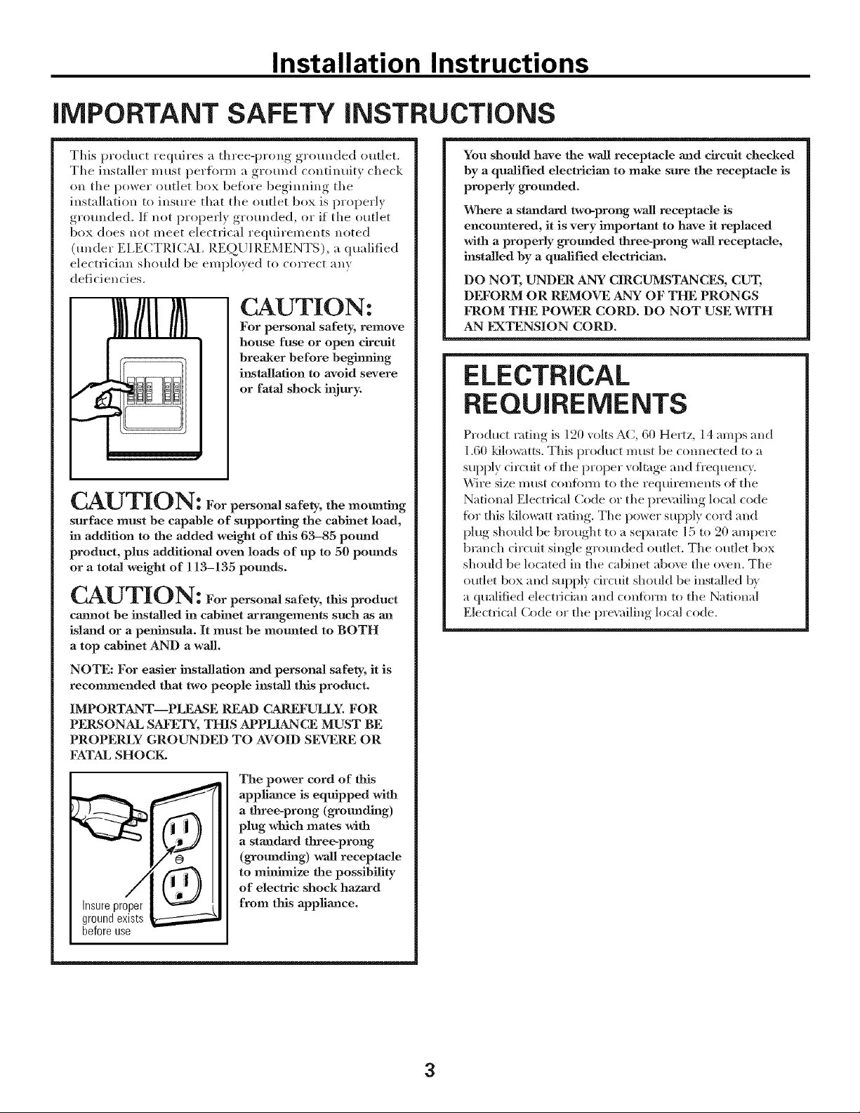
CAUTION:
lll//ll// 1
w
p
CAUTION: ForpersonalsafeS,themounting
surface must be capable of supporting the cabinet load,
in addition to the added weight of this 63-85 pound
product, plus additional oven loads of up to 50 pounds
or a total weight of 113-135 pounds.
CAUTION: For personal safety, this product
ca_mot be installed in cabinet arrangements such as an
island or a peninsula. It must be mounted to BOTH
a top cabinet AND a waJL
NOTE: For easier installation and personal safety, it is
recommended that two people install tlfis product.
IMPORTANT--PLEASE READ CAREFULLY. FOR
PERSONAL SAFETY, THIS APPLIANCE MUST BE
PROPERLY GROUNDED TO AVOID SEVERE OR
FATAL SHOCK.
For personal safety, remove
house fuse or open circuit
breaker before beginning
installation to avoid severe
or fatal shock injury.
You should have the wall receptacle and circuit checked
by a qualified electrician to make sure the receptacle is
properly grounded.
Where a standard two-prong wall receptacle is
encountered, it is very important to have it replaced
with a properly grounded three-prong wa3l receptacle,
installed by a qualified electriciaaa.
DO NOT, UNDFa;t ANY CIRCUMSTANCES, CUT,
DI?_'ORM OR REMOVE ANY OF THE PRONGS
FROM THE POWER CORD. DO NOT USE WITH
AN EXTENSION CORD.
ELECTRICAL
REQUIREMENTS
Produrt rating is 120 volts AC, 60 He_z, 14 amps and
1.60 kilowatts. This product must be connected to a
supply drcuit of tile proper voltage and _'equencv.
Wire size must confimn to the requirements of the
National Electrical (?,ode or the l)re\;filing local code
for this kilowatt rating. The power supply cord and
plug should be brought to a separate l 5 to 20 ampere
branch drcuit single grotmded outlet. The outlet box
should be located in the cabinet abo\v the oren. The
outlet box and supply drctfit should be installed by
a qualified electddan and confiwm to the National
Electrical Code or the pre\uiling local code.
Insure proper
ground exists
before use
Tile power cord of this
appliaJace is equipped with
a three-prong (grounding)
plug which mates with
a standard three-prong
(grounding) wall receptacle
to m_ize the possibility
of electric shock hazard
from tlfis appliance.
3
Page 4
Installation Instructions
HOOD EXHAUST
NOTE: Read these next two pages only if you plml to vent your exhaust to the
outside. If you plan to recirculate the air back into the room, proceed to page 6.
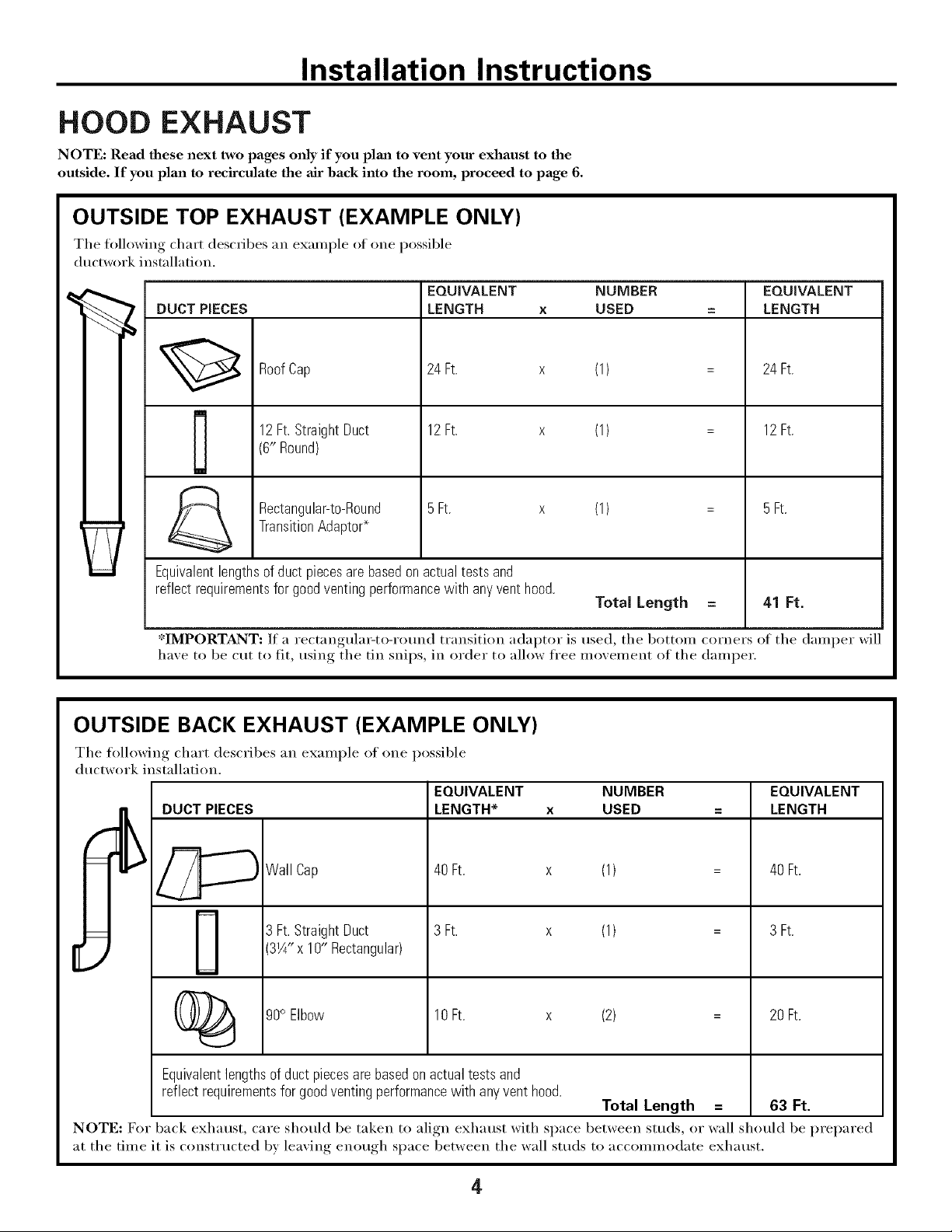
OUTSIDE TOP EXHAUST (EXAMPLE ONLY)
The following chart describes an example ot one possible
ductwork instnllation.
EQUIVALENT NUMBER
DUCT PIECES
12Ft.StraightDuct 12Ft. x
RoofCap 24 Ft. x
(6" Round)
-_ Rectangular-to-Round 5Ft. x
Equivalentlengthsof duct piecesarebasedonactualtestsand
reflectrequirementsfor goodventingperformancewith anyventhood.
*IMPORTANT: If a rectangula_to-rotmd transition adaptor is used, the bottom corners of the damper will
haxe to be cut to fit, using the tin snips, in order to allow free moxement of the damper.
TransitionAdaptors
LENGTH x USED
OUTSIDE BACK EXHAUST (EXAMPLE ONLY)
(1)
(1)
(1)
Total Length
EQUWALENT
LENGTH
24 Ft.
12Ft.
5Ft.
41 Ft.
The following chart describes an example ot one possible
ductwork installation.
EQUIVALENT NUMBER EQUIVALENT
_Wall Cap 40Ft. x (1) 40Ft.
DUCT PIECES LENGTH* x USED -- LENGTH
(_ 90° Elbow 10Ft. x (2) 20Ft.
Equivalentlengthsof ductpiecesarebasedonactualtestsand
reflectrequirementsfor goodventingperformancewith anyvent hood.
NOTE: For back exhaust, care should be taken to align exhaust with space between studs, or wall should be prepared
at the time it is constructed by leaving enough space between the wall studs to accommodate exhaust.
3 Ft.StraightDuct 3 Ft. x (1) 3 Ft.
3W' x 10" Rectangular)
Total Length = 63 Ft.
4
Page 5
Installation Instructions
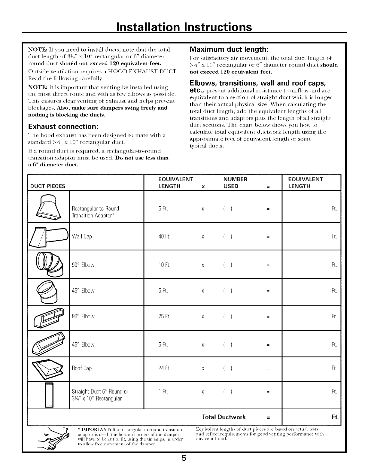
NOTE: If wm need to install ducts, note that the total
duct lengti_ of 3¼" x ] 0" rectangular or 6" diameter
round duct should not exceed 120 equivalent feet.
Outside ventilation requires a HOOD EXHAUST DUCT.
Read the fi_llowing careflfllv:
NOTE: It is important that venting be installed using
the most direct route and with as few elbows as possible.
This ensures clear venting of exhaust and helps prevent
blockages. Also, make sure dmnpers swing freely and
nothing is blocking the ducts.
Exhaust connection:
The hood exhaust has been designed to mate with a
standard 3¼" x 10" rectangular duct.
If a round duct is required, a rectangula_to-round
transition adaptor must be used. Do not use less than
a 6" diameter duct.
EQUIVALENT NUMBER EQUIVALENT
DUCT PIECES LENGTH x USED = LENGTH
Rectangular-to-Round 5Ft. x ( ) = Ft.
TransitionAdapto¢
Maximum duct length:
For s;Kislhctorv air movement, the total duct length of
3¼" x 10" rectangular or 6" diameter round duct should
not exceed 120 equivalent feet.
Elbows, transitions, wall and roof caps,
etc., present additional resistance to airth,w and are
eqtfiwdent to a section of straight duct which is longer
than their actual physical size, When calculating the
total duct length, add the eqtfiwdent lengths of all
transitions and adaptors plus the length of all straight
duct sections, The chart below shows you how to
calculate total eqtfiwdent ductwork length using the
approximate leer of eqtfiwdent length of some
typical ducts.
Wall Cap 40 Ft. x ( ) = Ft.
()_ 90° Elbow 10Ft. x ( ) = Ft.
45° Elbow 5Ft. x ( ) = Ft.
90° Elbow 25 Ft, x ( ) = Ft,
45° Elbow 5Ft. x ( ) = Ft.
RoofCap 24 Ft. x ( ) = Ft.
StraightDuct6" Roundor 1Ft. x ( ) = Ft.
3W' x 10" Rectangular
Total Duetwork = Ft.
adaptor is use(L the bottom corners of Ihe d_llllpeF _/lld reflect requirem_ nls tk)r good venling performance x_itll
xdll have to be Ctll tO _lt, using the tin snips, in order any vent hood.
* IMPORTANT: If a re<tangtdar-to-round transilion Equivalenl 1<ngths o[ du<t pie_ es are bas(d on aclual lests
to allm_fl-eellll)_,{_lll( 111 of Ih( d{llllpel.
5
Page 6
Installation Instructions
DAMAGE - SHIPMENT/
iNSTALLATiON
* If the unit is damaged in shipment, retm'n the
unit to the store in which it was bought fl)r repair
or replacement.
o If the _it is damaged by the customer, repair or
replacement is the Iesponsibility of the customer.
o If the unit is damaged by the installer (if other
than the customer), repair or replacement must
be made by arrangement between customer and
installer.
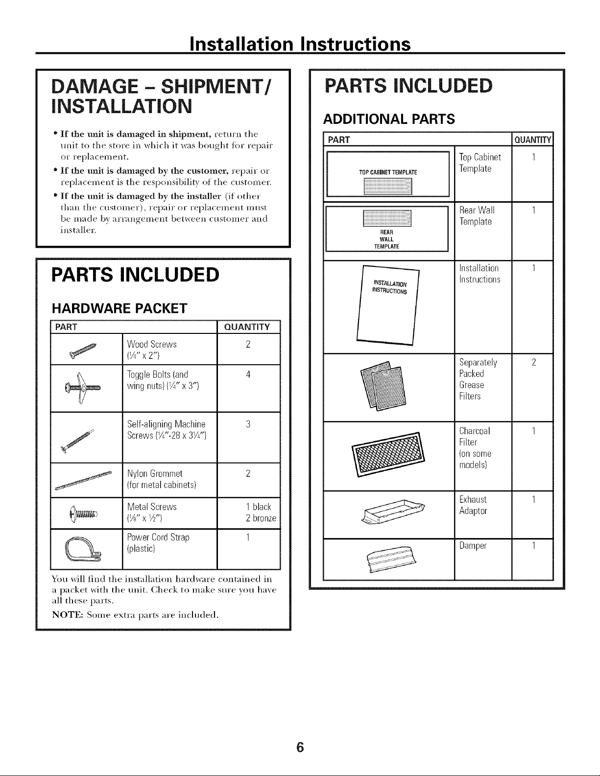
PARTS INCLUDED
HARDWARE PACKET
PART QUANTITY
Wood Screws 2
(¼" x2")
ToggleBolts(and 4
wing nuts)(¼" x 3")
PARTS iNCLUDED
ADDITIONAL PARTS
TopCabinet
TOPCABINETTEMPLATE
REAR
WALL
TEMPLATE
-------._.__.__
INSTALLATION
iNSTRUCTIONS
Template
RearWall
Template
Installation
Instructions
Separately
Packed
Grease
Filters
QUANTITY
Self-aligningMachine 3
Screws(W'-28 x3Y4")
NylonGrommet 2
(for metal cabinets)
Metal Screws 1 black
(W' x 1_,,) 2 bronze
Power Cord Strap 1
(plastic)
You will find the installation hardware contained in
a packet with the unit. Check to make sure w)u have
all these parts.
NOTE: Some extra parts are included.
Charcoal
Filter
(onsome
models)
Exhaust
Adaptor
Damper
6
Page 7
Installation Instructions
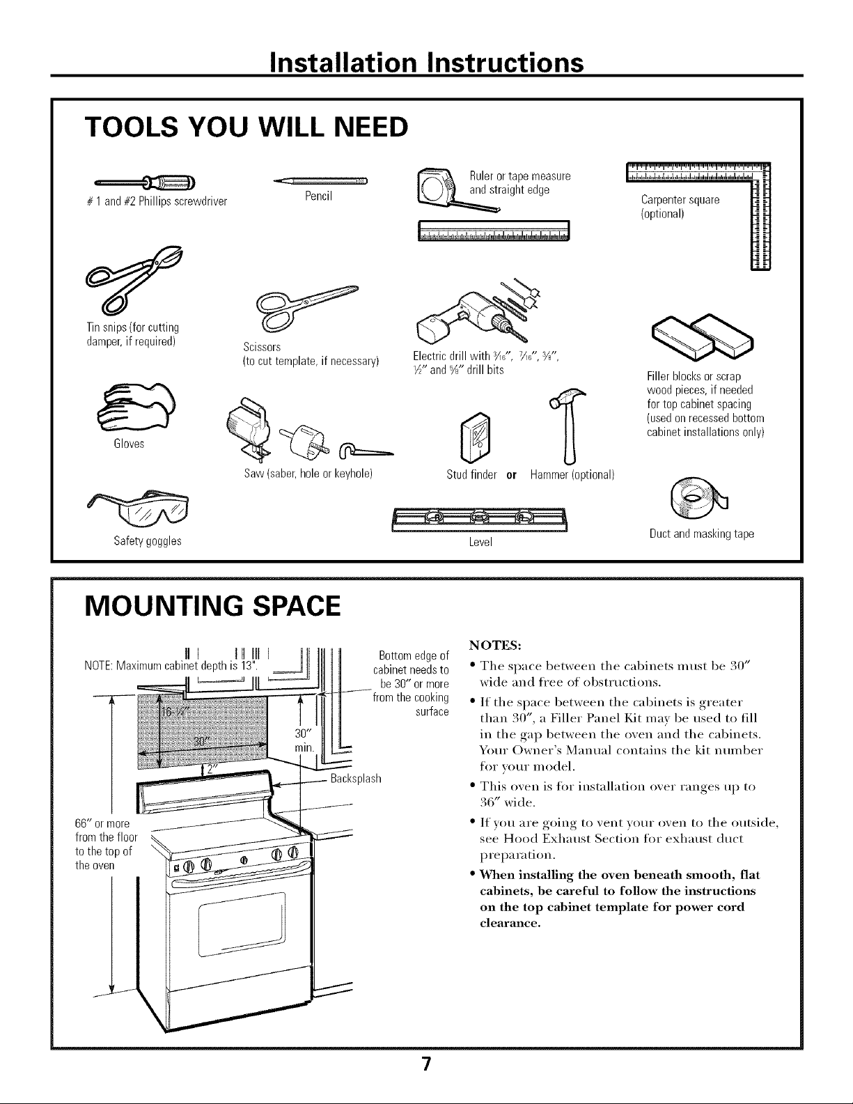
TOOLS YOU WILL NEED
# 1and#2Phillipsscrewdriver
Tinsnips(forcutting
damper,if required)
Gloves
Scissors
(tocut template,if necessary)
Pencil
Rulerortapemeasure
aightedge
Electricdrill with s/116",7/11g',syu,-
1½-and%" drillbits
(optional)
Carpentersquare
Fillerblocksor scrap
woodpieces,if needed
fortop cabinetspacing
(usedonrecessedbottom
cabinetinstallationsonly)
Saw(saber,holeor keyhole)
Safetygoggles
MOUNTING SPACE
II] t[] III
NOTE:Maximumcabinetdepthis 13".
ill
66" ormore
fromthe floor
tothe top of
theoven
cabinetneedsto
fromthe cooking
Backsplash
Bottomedgeof
be30" or more
surface
Studfinder er Hammer(optional)
Level
NOTES:
" The space between the cabinets must be 30"
wide and fl'ee of obst_ uctions.
• If the space between the cabinets is greater
than 30", a Filler Panel Kit may be used to fill
in the gap between the oven and the cabinets.
Yore" Owner's Manual contains the kit nmnber
for vour model.
• This oven is tot installation over ranges up to
36" wide.
• If win are going to vent w)m" oven to the outside,
see Hood Exhaust Section for exhaust duct
preparation.
• When installing the oven beneath smooth, flat
cabinets, be careful to follow the instructions
on the top cabinet template for power cord
clearance.
Ductandmaskingtape
\
7
Page 8
Installation Instructions
I-]PLACEMENT OF THE MOUNTING PLATE
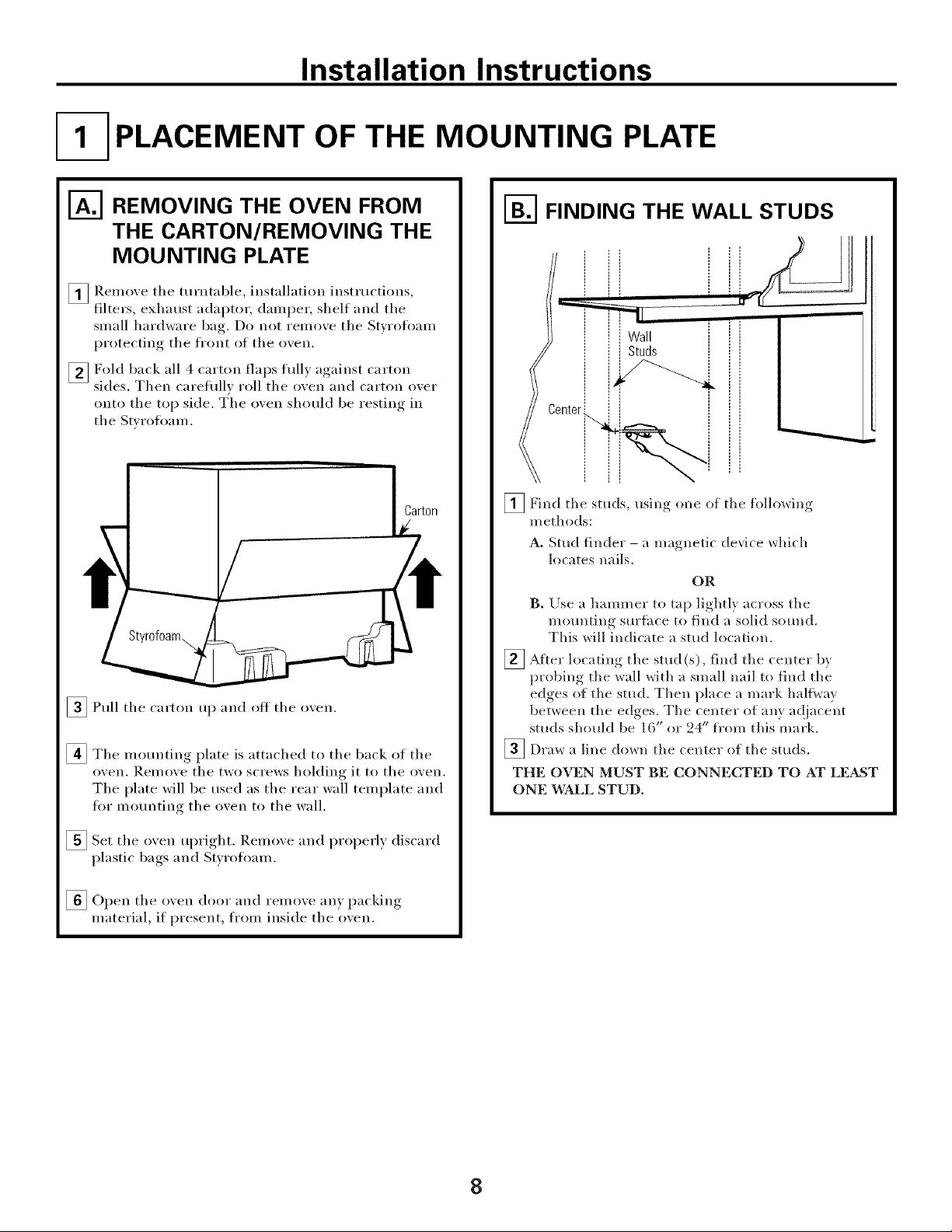
I_ REMOVING THE OVEN FROM
THE CARTON/REMOVING THE
MOUNTING PLATE
_ Remo_e the turntable, installation instructions,
filters, exhaust adaptor; (lampe_; shelf and the
small hardware bag. Do not reillo'_e the St_rofimm
protecting the front of the o_en.
_Fold back all 4 carton flaps full) against carton
sides. Then carefifllx roll the oxen and carton oxer
onto the top side. T'he oxen should be restino, ,., in
the St_ toil)am.
Carton
_Pull the carton up and off the oven.
_The motmting plate is attached to the back of the
oxen. I_einoxe the two screws holding it to the oxen.
The plate will be used as the rear wall template and
for motmting the oxen to the wall.
1-_ FINDING THE WALL STUDS
Wall
Studs
i
_Find the studs, usino one of the foHo_dn,,
methods:
A. Stud finder - a magnetic device which
locates nails.
OR
B. Use a hammer to tap lightly across the
mounting surthce to find a solid sound.
This will indicate a stud location.
_ Aiter locating the stud(s), find the center by
probing the wall with a small nail to find the
edges of the stud. Then place a mark halt\ray
between the edges, The center of any ac!jacent
studs should be 16" or 24" fl'om this mark.
_Draw a line down the center of the studs.
THE OVEN MUST BE CONNECTED TO AT LEAST
ONE WALL STUD.
_Set the oxen upright Remoxe and properl) discard
I)lastic bags, and St_roflmm.
[] )acking
Open the o_en door and relnoxe an} I
material, if present, fi'om inside the oxen.
8
Page 9

Installation Instructions
DETERMINING WALL PLATE LOCATION UNDER YOUR CABINET
Plate position - beneath flat bottom
cabinet
Mounting Plate Tabs
Bottom
""S,
At least 30", up to 36"
! the Cabinet
Plate position - beneath framed recessed
cabinet bottom
Mounting Plate Tabs
Touching the Bacl<
Frame
\
\
\
30" to Cool<top
!
Plate position - beneath recessed bottom
cabinet with front overhang
Mounting Plate with
TabsBelow Cabinet
Bottom the Same
Distance as the Front
Overhang Depth
, II
30"to Cool<top
Your cabinets may have decorative trim that interferes
with the oven installation. Remove the decorative trim
to install the oven properly and to make it level.
THE OVEN MUST BE LEVEL
Use a level to make sure the cabinet bottom is level.
If the cabinets have a fl'ont overhang only, with no
back or side fi'ame, install the mounting plate down
the same distance as the fi'ont overhang depth. This
will keep the oven level.
[]Measure the inside depth of the fi'ont overhang.
[] Draw a horizontal line on the back wall an equal
distance below the cabinet bottom as the inside
depth of the fi'ont overhang.
_For this b'pe of installation with fl'ont overhang only,
align the mounting tabs with this horizontal line, not
touching the cabinet bottom as described in Step D.
9
Page 10

Installation Instructions
ALIGNING THE WALL PLATE
\
^ _ LineonWall
H_lole iI Drawa Vertical
HoleC_/' _ _ _ .........................................5 ° ° s_ _s_6 _,__
I
CAUTION: Wear glo_es I
to a_oid cutting fingers on
sharp edges.
[]Draw a vertical line on the wall at the center of the 30"
wide space.
_Use the moui_ting plate as the template for the rear
wall. Place the mom_ting plate on the wall, making
sure that the tabs are touching the bottom of the
cabinet or the level line drawn in Step C for cabinets
with front overhm_g. Line up the notch mid center line
on the mounting plate to the center line on the wall.
[] X._l_ileholding the mounting plate with one hand,
draw drcles on the wall at holes A, B, C and D (see
illustration above/actual plate marked with arrows).
Four holes must be used for mounting.
,_, ,I,
AreaE I
[] Dlill holes on the circles. If there is a stud, chill a :"A(;"
-_------ HoleB
I<_ fromCenterof
i TopCabinet
i
/
/
/
/
i
HoleD
NOTE: Appearance and
shape of the motmting
plate may wu'v ti'om vom"
model.
NOTE: Holes C and D are inside area E. If neither
C nor D is in a stud, find a stud s()mewhere in area E
and draw a fifth drcle to line up with the stud. It is
important to use at least one wood screw nlounted
firmly in a stud to sui_port the weight of the oven.
Set the mounting plate aside.
hole fin" wood screws. For holes that don't line up with
a stud, dlill a %" hole fin" toggle bolts.
NOTE: DO NOT MOUNT THE PLATE
AT THIS TIME.
10
Page 11

Installation Instructions
INSTALLATION TYPES
This oven is designed h)r adaptation to the fi)llowing three
types of ventilation:
A. Outside Top Exhaust (Vertical Duct)
B. Outside Back Exhaust (Horizontal Duct)
C. Recirculating (Non-Vented Ductless)
OUTSIDE TOP EXHAUST
(VERTICAL DUCT)
1
(Choose A, B or C)
NOTE: This ()veil is shipped assembled fin" Outside Top
Exhaust (except for non-vented models). Select the type
of ventilation required for vom" installation and proceed
to that section.
_-] OUTSIDE BACK EXHAUST
(HORIZONTAL DUCT)
RECIRCULATING
(NON-VENTED DUCTLESS)
11
On models shipped fi)r
non-vented exhaust, a
disposable charcoal filter is
included with the oven and
needs to be installed to help
reulove si/loke and odors.
On models shipped fi)r
outside top exhaust, a
Charcoal Filter Accessory Kit
is required for the non-vented
exhaust. (See your Owner's
Manual fin" the kit nmnber.)
Page 12

Installation Instructions
OUTSIDE TOP EXHAUST (Vertical Duct)
INSTALLATION OVERVIEW
A1. Attach Mounting Plate to Wall
A2. Prepare Top Cabinet
A3. Install Adapter
A4, Mount Oven
A5. Ac!j ust Exhaust Adaptor
A6. Connect Ductwork
I-_ ATTACH THE MOUNTING
PLATE TO THE WALL
Attach the plate to the wall using toggle bolts. At least
one wood screw must be used to attach the plate to a
wall stud.
[]Remove the toggle wings fl'om the bolts.
[]Insert the bolts into the mounting plate
through the holes designated to go into drwvall
and reattach the toggle wings to '_A"onto each bolt.
To use toggle bolts:
Spacingfor Toggles
MoreThanWall
+l.-,-[._Thickness
Mounting
Plate
BoltEnd
_ Place the mounting plate against the wall and
insert the toggle wings into the holes in the wall to
mount the plate.
NOTE: Betore tightening toggle bolts and wood
scre_, make sure the tabs on the mounting plate
touch the bottom of the cabinet when pushed
flush against the wall and that the plate is properly
centered under the cabinet.
CAUTION: Be careflfl to axoid I)inchin'*_ fingers
between the back of the mounting plate and the wall.
_ Tighten all bolts. Pull the plate awax from the wall
to hel I) tighten the bolts.
12
Page 13

Installation Instructions
I-_ USE TOP CABINET TEMPLATE
FOR PREPARATION OF TOP
CABINET
You need to drill holes for the top sui)port screws, a
hole large, enouoh_ for the power cord to fit through,
and a cutout large enough for the exhaust adaptor.
" Read the instructions on the TOP CABINET
TEMPLATE.
" Tape it tmderneath the top cabinet.
" Drill the holes, following the instructions on the
TOP CABINET TEMPLATE.
CAUTION: _4ear safety o-oo-des when drillim, holes
in the cabinet bottom.
ASSEMBLE AND
INSTALL ADAPTOR
Damper
-- Exhaust
Adaptor
BlowerPlate
Backof
Oven
I-_ MOUNT THE OVEN
FOIl EASIER INSTAI,IATION AND PERSONAl,
SAFETY, WE RECOMMEND THAT TWO PEOPLE
INSTALL THIS OVEN.
IMPORTANT: Do not grip or use handle
during installation.
NOTE: If your cabinet is metal, use the nylon
grommet around the power cord hole to prevent
cutting of the cord,
NOTE: We recommend using filler blocks if the
cabinet fl'ont hangs below the cabinet bottom shelf.
IMPORTANT: If filler blocks are not
used, case damage may occur from over
tightening screws.
NOTE: When mounting the
oven, thread power cord
through hole in bottom
of top cabinet. Kee I) it tight
throughout Steps 1-3.
Do not pinch cord or lift
oxen by pulling cord.
_I,ifl tilt itoven,
fi)rward and hook
slots at back bottom
edge onto two lower
tabs of mounting
plate.
NOTE: On some models, the exhaust adaptor and
damper assembly may ah'eadv be assembled to the oven.
_ Place the oven in its ul_right position, with the top
of the trait lacing up.
NOTE: Make sure the blower fan blades are visible
and are pointing up.
_ Insert the tabs on each side of the damper into the
holes at the inside rear of the adaptor.
_ Attach the exhaust adaptor to the blower plate with
the two bronze metal screws provided.
Make sure that the damper pivots easily before
mounting oven.
You will need to make a(!iustments to assure proper
alignment with your house exhaust duct after the
()veil is installed'.
[_ Rotate front of
up against cabinet
bottoI//.
13
o_en
Page 14

Installation Instructions
MOUNT THE OVEN (continued)
CabinetFront
F/ CabinetBottomShelf
Equivalent
I !! III NLI! /I[IItODepth
z!/_ FilleI Block
Self-AligningScrew
OvenTop
[]Attach tile (wen to the top cabinet by inserting
3 sell'aligning screws through outer top cabinet
holes. Turn two hill turns on each screw. Be sure
to keep power cord tight. Be caacefnl not to pinch
the cord, especially when mounting flnsh to
bottom of cabinet.
ofCabinet
Recess
L_I
ADJUST THE EXHAUST
ADAPTOR
Open tile top cabinet and a(!iust tile exhaust adaptor
to connect to tile house duct.
Damper
1
Backof
Oven
I-_ CONNECTING DUCTWORK
HouseDuct
[] Tighten tile three screws to tile top of tile oxen
completely. (X._hile tightening screws, hold the
oxen ill place against tile wall and tile top cabinet.)
[]Install filters. See tile Owner s Manual
grease
packed with tile oxen.
-i
[] ExteIld tile hot/se dt/ct dowll to COIlllect to
tile exhaust adaptor.
Seal exhaust durt ioints using
] . , duct tape.
14
Page 15

Installation Instructions
OUTSIDE BACK EXHAUST IHorJzo.talD.ctl
INSTALLATION OVERVIEW
B1. Prepare Rear _,_all
B2. Attach Exhaust Adaptor to
_,_all Plate
B3, Attach Mounting Plate
to X,Vdl
B4. Prepare Top Cabinet
BS. A¢!just Blower
B6. Motmt the Oven
1
Kmmmmmmmmmd
PREPARING THE REAR WALL
FOR OUTSIDE BACK EXHAUST
You need to cut an I
outside exhaust.
_Read the instructions on the REAR X,VAI,I,
TEMPLATE.
_Tape it to the rear wall, lining up with the holes
pre_iously drilled for holes A and B in the wall
pla re.
_Cut the )enino the instHictions of theI _, following
REAR _£M,I, TEMPI,ATE.
O
o )eniw, in the rear wall tot
ATTACH THE EXHAUST
ADAPTOR TO THE OVEN REAR
PANEL
_ Unscrew and remove the exhaust adaptor
assembly fl'om the top of the oven.
[ _ _ Exhaust
i ___ Adaptor
_Attach the exhaust adaptor to the oxen rear
panel bx sliding it into the guides at the top
center of the back of the oxen.
__ Damper
Exhou t ,o ..
._i_ Guide
Guide _ Locking
Push in securely tmtil it is in the lower locking tabs.
Take care to assure the damper hinge, is installed so
that it is at the top and that the damper .swin,,s.,.freely.,
0 Tabs
15
Page 16

Installation Instructions
ATTACH THE MOUNTING
PLATE TO THE WALL
Attach the plate to the wall using toggle bolts. At least
one wood screw must be used to attach the plate to a
wall stud.
[] I/emove the toggle wings fi'om the bolts.
[]Insert the bolts into the mounting plate through
the holes designated to go into dr}svall and reattach
the toggle wings to :_A"onto each bolt.
To use toggle bolts:
Spacingfor TogglesMore
-,-I_,-,,-!_,_ThanWallThickness
i
Mounting
Plate
ToggleWings
[=ff_ USE TOP CABINET TEMPLATE
FOR PREPARATION OF TOP
CABINET
You need to drill holes for the top support screws and
a hole large enouoh for the power cord to fit throu ,h
® Read the instructions on the TOP CABINET
TEM PI,ATE.
* Tape it underneath the top cabinet.
* Drill the holes, following the instructions on the
TOP CABINET TEMPLATE.
CAUTION: \'_Teal"safet) goggles when drilling holes in
the cabinet bottom.
B01tEnd
_ Place the mounting plate against the wall and
insert the toggle wings into the holes in the wall
to mount the plate.
NOTE: Betore tightening toggle bolts and wood
scre_, make sure the tabs on the mounting plate
touch the bottom of the cabinet when pushed flush
against the wall and that the plate is properly
centered under the cabinet.
CAUTION: Be careflfl to axoid I)inching, finge_
between the back of the mounting, I)late and the wall.
_ Tighten all bolts. Pull the from the wall
to help tighten the bolts.
plate
16
Page 17

Installation Instructions
ADAPTING BLOWER FOR
OUTSIDE BACK EXHAUST
[] Renmve the two screws that hold the blower plate
and remove the screw holding the blower motor
to the oven. Slide blower plate fl'om trader its
retaining flange.
Retaining 1_ _
Flange ,_,4k _,___.._.._ Blower Plate
--_
[] Careflflly the blower trait. The wirespull
will extend far enough to allow you to a(!just
the blower unit.
O[lt
_] Place the 1)lox_er unit back into the opening.
CAUTION: Do not pull or stretch the blower
refit wiring. Make sure the wires axe not pinched.
NOTE: The blower unit exhaust openhlgs should
match exhaust openh_gs on rear of oven.
] Replace the blower plate in the same position
as before and replace the screws for the
blower plate and blower motor.
BlowerPlateScrews
BlowerPlate
.,_ BackofOven
BlowerMotor Screw
_ Rotate blower trait counterclockwise 180 °.
Before Rotation
Back of
Oven
After Rotation
_Roll the blower trait 90 ° so that tan blade
openings are facing ot/t the back of the
o_, eIl.
Before Rolling --_ After Rolling _
t o °
Backof
Oven
Back of
Oven
_17
_ " Oven
ackof
Backof
Oven
Page 18

Installation Instructions
MOUNT THE OVEN
CabinetFront
CabinetBottomShelf
FillerBlock
to Depth
of Cabinet
T quivalent
Recess
FOIl EASIER INSTAI,IATION AND PERSONAI,
SAFETY, X.VERECOMMEND THAT TWO PEOPLE
INSTALL THIS OVEN.
IMPORTANT: Do not grip or use handle
during installation.
NOTE: If vour cabinet is metal, use the nylon
gronmlet around tile power cord hole to prevent
cutting ot tile cord.
NOTE: We recoumlend using filler blocks if tile
cabinet front hangs below tile cabinet bott(nn shelf.
IMPORTANT: If filler blocks are not
used, case damage may occur from over
tightening screws.
NOTE: When mounting
tile oven, thread power
cord through hole ill
bottonl of top cabinet.
Kee I) it tight throughout
Steps 1-3. Do not pinch
cord or lifi oven bv
Imllin(*', cord.
[]I,ifl ()veil, it
fin'ward and hook
slots at back l)()ttom
edge onto two lower
tabs of mounting plate.
tilt
Self-AligningScrew
OvenTop
[]Attach tile oven to tile top cabinet by inserting
3 sell=aligning screws through outer top cabinet
holes. Turn two fllll ttu'ns on each screw. Be sure
to keep power cord tight. Be careful not to pinch
the cord, especially when mounting flush to
bottom of cabinet.
[] Tighten tile three screws to tile top of tile oven
c(mlpletely. (X.Vhile tightening screws, hold the
oxen in place against tile wall and tile top
cabinet.)
/
_ Rotate front (If oven lip
against cabinet 1)()ttom.
\
_ Install grease filters. See tile Owner's Manual
packed with tile oxen.
18
Page 19

Installation Instructions
RECIRCULATING INon-VentedDuctless)
INSTALLATION OVERVIEW
C1. Attach Mounting Plate to _'all
C2. Prepare Top Cabinet
C3. Adjust Blower
C4. Mount the Oven
C5. Install Charcoal Filter
I-_ ATTACH THE MOUNTING
PLATE TO THE WALL
l
Attach the plate to the wall using toggle bolts. At
least one wood screw I/ltlSt be used to attach the
plate to a wall stud.
[]Remove the toggle wings fl'om the bolts.
[]Insert the bolts into the mounting plate through
the holes designated to go into dr xsvall and
reattach the toggle wings to :Y," onto each bolt.
To use toggle bolts:
Spacingfor Toggles
MoreThanWall
-,.-I..-,.-i_,_Thckness
_ Place the mounting plate against the wall and
insert the toggle wings into the holes in the wall to
mount the plate.
NOTE: Betore tightening toggle bolts and wood
scre_, make sure the tabs on the mounting plate
touch the bottom of the cabinet when pushed flush
against the wall and that the plate is properly
centered under the cabinet,
CAUTION: Be careflfl to axoid I)inchin<*_ fingers,
between the back of the mounting plate and the wall.
_ Tighten all bolts. Pull the plate away fi'om the wall
to hel I) tighten the bolts.
| USE TOP CABINET TEMPLATE
FOR PREPARATION OF TOP
CABINET
You need to drill holes fl)r the top sui)port screws and
a hole large enotwh for the power cord to fit throuoh
Mounting
Plate
" Read the instructions on the TOP CABINET
if,
BoltEnd
TEMPI,ATE.
" Tape it underneath the top cabinet.
" Drill the holes, fl_llowing the instructions on the
TOP CABINET TEMPLATE.
CAUTION: X_'ear safety goggles when drilling holes
in the cabinet bottom.
19
Page 20

Installation Instructions
ADAPTING BLOWER
FOR RECIRCULATION
NOTE: The exhaust adaptor with dmnper is not
needed for recirculating models. Ym may want to
sa',e then/ for possible flmu'e use.
[]Remove and that hold blower andplate
blower trait to the oxen.
Blower Plate Screws
sa',e screws
B,owerP,ate
Back of Oven
_ Slide the blower plate from trader its retainim,
flanoe and lift it off.
letaining
Blower Plate
_Roll the blower rant 30 so that tim blade o )enings
are thcing toward the fi'(mt ()f the oxen.
B011
Careflfllv roll out the blower trait The wires
will extend far en u,,h to allow }(m to a(!lUSt the
blower trait.
0 (Y "
2O
Page 21

Installation Instructions
ADAPTING BLOWER FOR
RECIRCULATION (continued)
_] Place the blower unit back into the o )ening.
CAUTION: Do not pull or stretch the blower unit
wiring, Make sure the wires are not pinched,
[] Replace blower plate and replace screws for blower
plate and blower motor remoxed in Step 1.
Blower Plate Screws
__ Blower Plate
I Back of Oven
l
NOTE: When motmting
the oven, thread power
cord through hole in
bottom of top cabinet.
Kee I) it tight throughout
Steps 1-3. Do not pinch
cord or lift oven by
mllin , cord
/
_ Rotate fFont of oxen
up against cabinet
bottoln.
CabinetFront
CabinetBottomShelf
_I,ifl oven, tilt it
flwward and hook
slots at back bottom
edge onto two lower
tabs of mounting plate.
MOUNT THE OVEN
FOIl EASIER INSTAI,I.¢TION AND PERSONAI,
SAFETY, WE RECOMMEND THAT TWO PEOPLE
INSTALL THIS OVEN.
IMPORTANT: Do not grip or use handle
during installation.
NOTE: If yore" cabinet is metal, use the nylon
grommet around the power cord hole to prevent
cutting of the cord.
NOTE: We recommend using filler blocks if the
cabinet front hangs below the cabinet bottom shelf.
IMPORTANT: If filler blocks are not used,
case damage may occur from over tightening
screws.
Equivalent to Depth
f Cabinet Recess
Self-Aligning Screw
Oven Top
21
Page 22

Installation Instructions
MOUNT THE OVEN
(continued)
_Attach the oven to the top cabinet by inserting
3 self aligning screws through outer top cabinet
holes. Turn two fllll ttlI'IIS on each screw. Be sure
to keep power cord tight. Be careful not to pinch
the cord, especially when mounting flush to
bottom of cabinet.
[] Tighten the three screws to the top of the oxen
completely. (X_hile tightening screws, hold
the oxen in place against the wall and the top
cabinet.)
INSTALLING THE CHARCOAL
FILTER
_ Remoxe 2 screws on to ) of grille using a
Phillips screwdrix er.
_Open the door .)0 .
_ Remoxe the grille.
J
J
_ ]nsert the filter into the of the )enintop
between the side support slots,
( o
o
_CL_
Filter
_lnstall filters. See the Owner Manual
grease
packed with the o_en.
S /
_Push the filter all the wax in where it will rest at
an angle,
[] Replace the grille and the 2 ,_crews.
_ Close the door.
c S
_j__j
Insertmesh-sideup
22
Page 23

Installation Instructions
BEFORE YOU USE YOUR
[_ ake sure the o_en h;Js been installed
according to instructions.
_3
_ Remove all packing materi_d from the o_en.
OVEN
[_ Read the O_ner's Manual.
['_ KEEP INS%M,LATION INSTRUCTIONS
FOR THE I.OCAI. INSPECTOR'S USE.
_ Repl_lce house fuse or turn breaker back on.
IllIIII
Plug po_,,,er cord into a dedicated 15 to 20 amp
%
electrical outlet.
Insure proper
23
Page 24

Printed in (]hina
 Loading...