

GE JVM1650BB001, JVM1650BB002, JVM1650BB003, JVM1650BB004, JVM1650BB005 Installation Guide
...Page 1
Installation
Overthe Range
Instructions
Questions? Call GEAnswer Center at 800.626.2000or Visit our Website at: GEAppliances.com
Microwave Oven
BEFORE YOU BEGIN
Read these instructions completely and carefully.
• IMPORTANT - S_,vethese
insuucfions for local inspector's use.
• IMPORTANT - Obse,ve_,ll
governing codes and ordinances.
• Note to Installer - Besure to leave these
insUucfions with the Gonsumer.
• Note to Consumer - Keep these
instructions for fllu_ie reference.
• Skill level - Installation of this appliance requires
basic mechanical and electrical skills.
• Proper installation is the responsibility of the installer.
• Product failure due to improper installation is not
covered under the X_rarranty.
/
/
/
/
For a Spanish version of this manual, visit our Website at www.GEAppliances.com.
Para consultar una version en espaKol de este manual de instrucciones, visite nuestro sitio
de internet www.GEAppliances.com.
READ CAREFULLY.
KEEP THESE INSTRUCTIONS.
Page 2
Installation Instructions
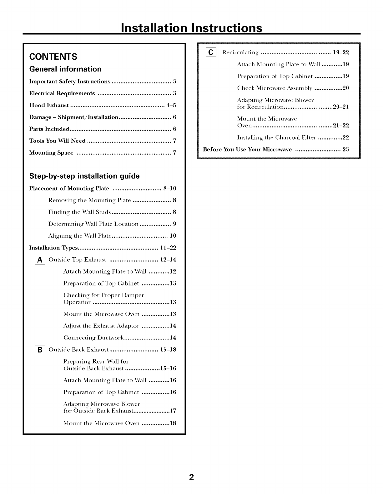
CONTENTS
General information
Important Safety Instructions .................................. 3
Electrical Requirements .......................................... 3
Hood Exhaust ...................................................... 4-5
Damage - Shipment/Installation .............................. 6
Parts Included .......................................................... 6
Tools You Will Need ................................................ 7
Mounting Space ...................................................... 7
Step-by-step installation guide
Placement of Mounting Plate ............................ 8-10
Removing the Mounting Plate ...................... 8
Finding the Wall Studs .................................. 8
Determining Wall Plate I,ocafion .................. 9
[] Recirculating ........................................ 19-22
Attach Mounting Plate to Wall ............ 19
Preparation of Top Cabinet ................ 19
Check Microwave Assembly ................ 20
Adapting Microwave Blower
for Recirculation ............................ 20-21
Mount the Microwave
Oven .............................................. 21-22
Installing the Charcoal Filter. ............. 22
Before You Use Your Microwave .......................... 23
Aligning the Wall Plate ................................ 10
Installation Types .............................................. 11-22
_ Outside Top ............................
Attach Mounting Plate to Wall ............ 12
Preparation of Top Cabinet ................ 13
Checking for Proper Damper
Operation ............................................ 13
Mount the Microwave Oven ................ 13
Adjust the Exhaust Adaptor ................ 14
Connecting Ductwork .......................... 14
_]_ Outside Back Exhaust 15-18
Preparing Rear Wall for
Outside Back Exhaust .................... 15-16
Attach Mounting Plate to Wall ............ 16
Preparation of Top Cabinet ................ 16
Adapting Microwave Blower
for Outside Back Exhaust ...................... 17
Exhaust
12-14
Mount the Microwave Oven ................ 18
2
Page 3

Installation Instructions
iMPORTANT SAFETY iNSTRUCTiONS
This product requires a three-prong grounded outlet°
The installer must perK_rm a ground continuity check
on the power outlet box befbre beginning the
installation to insure that the out|et box is proper|y
grounded. If not properly grounded, or if the out|et
box does not meet electrical requirements noted
(under EI,ECTRICAI, REQUIREMENTS), a qualified
electrician should be employed to correct any
deficiencies.
CAUTION: For personal
safety, remove house fuse
or open circuit breaker
before beginning
installation to avoid severe
or fatal shock injury.
w
CAUTION: For personal safety, the mounting surface
must be capable of supporting the cabinet load, in
addition to the added weight of this 63-85 pound
product, plus additional oven loads of up to 50 pounds
or a total weight of 113-135 pounds.
CAUTION: For personal safety, this product cannot
be installed in cabinet arrangements such as an island or
a peninsula. It must be mounted to BOTH a top cabinet
AND a wall.
You should have the wall receptacle and circuit checked
by a qualified electrician to make sure the receptacle is
properly grounded.
Where a standard two-prong wall receptacle is
encountered, it is very important to have it replaced
with a properly grounded three-prong wall receptacle,
installed by a qualified electridan.
DO NOT, UNDER ANY CIRCUMSTANCES, CUT,
DEFORM, OR REMOVE ANY OF THE PRONGS
FROM THE POWER CORD. DO NOT USE WITH
AN EXTENSION CORD.
ELECTRICAL
REQUIREMENTS
Product radng is 120 volts AC, 60 Hertz, 15 amps, and
1.58 ldlowatts. This product must be connected to a
supply circuit of the proper voltage and flequency:
Wire size must conform to the requirements of the
National Electrical Code or the prevailing local code
for this kilowatt rating. The power supply cord and
plug should be brought to a separate 15 to 20 ampere
branch circuit single grounded outlet. The outlet box
should be located in the cabinet above the microwave
oven. The outlet box and supply circuit should be
installed by a qualified electrician and conform to the
National Electrical Code or the prevailing local code.
NOTE: For easier installation and personal safety, it is
recommended that two people install this product.
IMPORTANT--PLEASE READ CAREFULLY. FOR
PERSONAL SAFETY, THIS APPLIANCE MUST BE
PROPERLY GROUNDED TO AVOID SEVERE OR
FATAL SHOCK.
The power cord of this appliance is equipped with a
three-prong (grounding)
plug which mates with a
standard three-prong
(grounding) wall receptacle
to minimize the possibility
of electric shock hazard
from this appliance.
Insure proper
ground exists
before use
3
Page 4
Installation Instructions
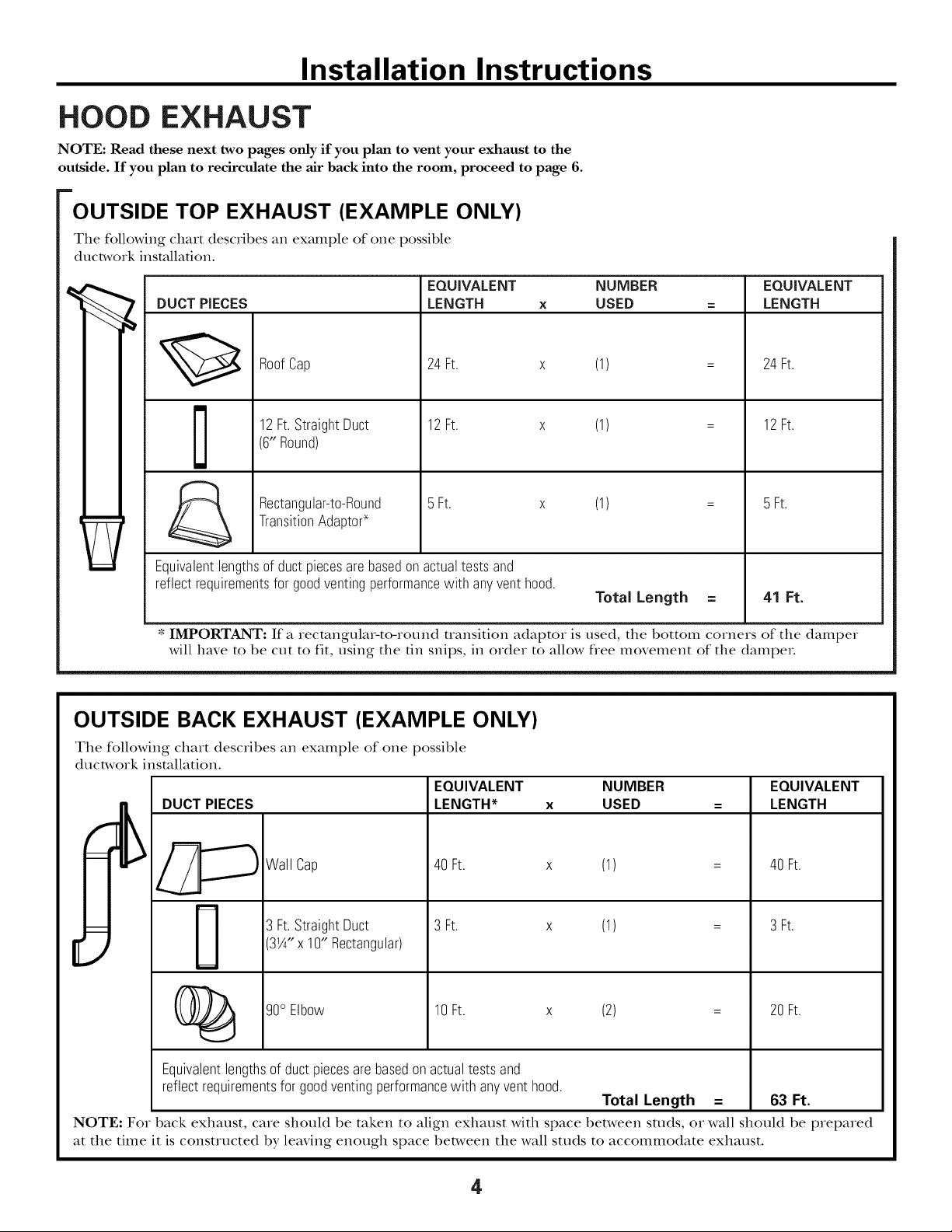
HOOD EXHAUST
NOTE: Read these next two pages only if you plan to vent your exhaust to the
outside. If you plan to recirculate the air back into the room, proceed to page 6.
OUTSIDE TOP EXHAUST (EXAMPLE ONLY)
The following chart describes an example of one possible
ductwork installation.
EQUIVALENT NUMBER EQUIVALENT
DUCT PIECES LENGTH x USED = LENGTH
24Ft. x (1)
12Ft.StraightDuct
RoofCap
(6"Round)
TransitionAdapto¢
Rectangular-to-Round
Equivalentlengthsof ductpiecesarebasedonactualtests and
reflectrequirementsfor goodventingperformancewith anyventhood.
* IMPORTANT: If a rectangular-to-round mmsition adaptor is used, the bottom corners of the damper
will have to be cut to fit, using the fin snips, in order to allow flee movement of the dampeL
12Ft. x (1)
5 Ft. x (1) =
OUTSIDE BACK EXHAUST (EXAMPLE ONLY)
The following chart describes an example of one possible
ductwork installation.
EQUIVALENT
DUCT PIECES
LENGTH* x
24Ft.
12Ft.
5 Ft.
Total Length = 41 Ft.
NUMBER
USED
EQUIVALENT
LENGTH
Wall Cap
3 Ft.StraightDuct
31A" x 1O"Rectangular)
(_ go° Elbow 10Ft. x (2) = 20Ft.
Equivalentlengthsof ductpiecesarebasedonactualtestsand
reflectrequirementsforgoodventingperformancewith anyvent hood.
NOTE: For back exhaust, care should be taken to align exhaust with space between studs, or wall should be prepared
at the time it is constructed by leaving enough space between the wall studs to accommodate exhaust.
40Ft.
3 Ft.
(1)
(1)
Total Length = 63 Ft.
40Ft.
3 Ft.
4
Page 5
Installation Instructions
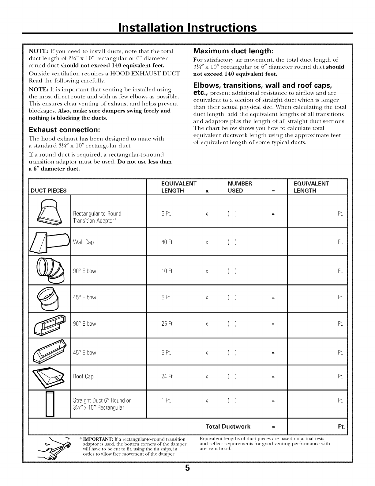
NOTE: If you need to install ducts, note that the total
duct length of 3¼"x 10" rectangular or 6" diameter
round duct should not exceed 140 equivalent feet.
Outside ventilation requires a HOOD EXHAUST DUCT.
Read the following careflflly.
NOTE: It is important that venting be installed using
the most direct route and with as few elbows as possible.
This ensures clear venting of exhaust and helps prevent
blockages. Mso, make sure dampers swing freely and
nothing is blocking the ducts.
Exhaust connection:
The hood exhaust has been designed to mate with
a standard 3¼" x 10" rectangular duct.
If a round duct is required, a rectangular-to-round
uansition adaptor must be used. Do not use less than
a 6" diameter duct.
EQUIVALENT
DUCT PIECES
Rectangular-to-Round
TransitionAdapto¢
LENGTH
5Ft.
Maximum duct length:
For satisfactory air movement, the total duct length of
3¼"x 10" rectangular or 6" diameter round duct should
not exceed 140 equivalent feet.
Elbows, transitions, wall and roof caps,
etc., present additional resistance to airflow and are
equivalent to a section of suaight duct which is longer
than their actual physical size. When calculating the total
duct length, add the equivalent lengths of all uansifions
and adaptors plus the length of all suaight duct sections.
The chart below shows you how to calculate total
equivalent ducrwork length using the approximate feet
of equivalent length of some typical ducts.
NUMBER
x USED
x ( )
= LENGTH
=
EQUIVALENT
Ft.
%
G
O
O
Wall Cap
%0 Elbow
45° Elbow
%0 Elbow
45° Elbow
RoofCap
StraightDuct6" Roundor
3%"x 10" Rectangular
40 Ft.
10 Ft.
5Ft.
25 Ft.
5Ft.
24Ft.
1Ft.
x ( )
x ( )
x ( )
x ( )
x ( )
x ( )
x ( )
=
=
=
=
=
=
=
Ft.
Ft.
Ft.
Ft.
Ft.
Ft.
Ft.
* IMPORTANT: If a rectangular-to-round transition
adaptor is used, the bottom corners of the damper
will hme to be cut to fit, using the tin snips, in
order to allow fi'ee movement of the damper.
Total Ductw0rk
Equivalent lengths of duct pieces are based on actual tests
and reflect requirements tot good venting pertormance with
any vent hood.
==
5
Ft.
Page 6
Installation Instructions
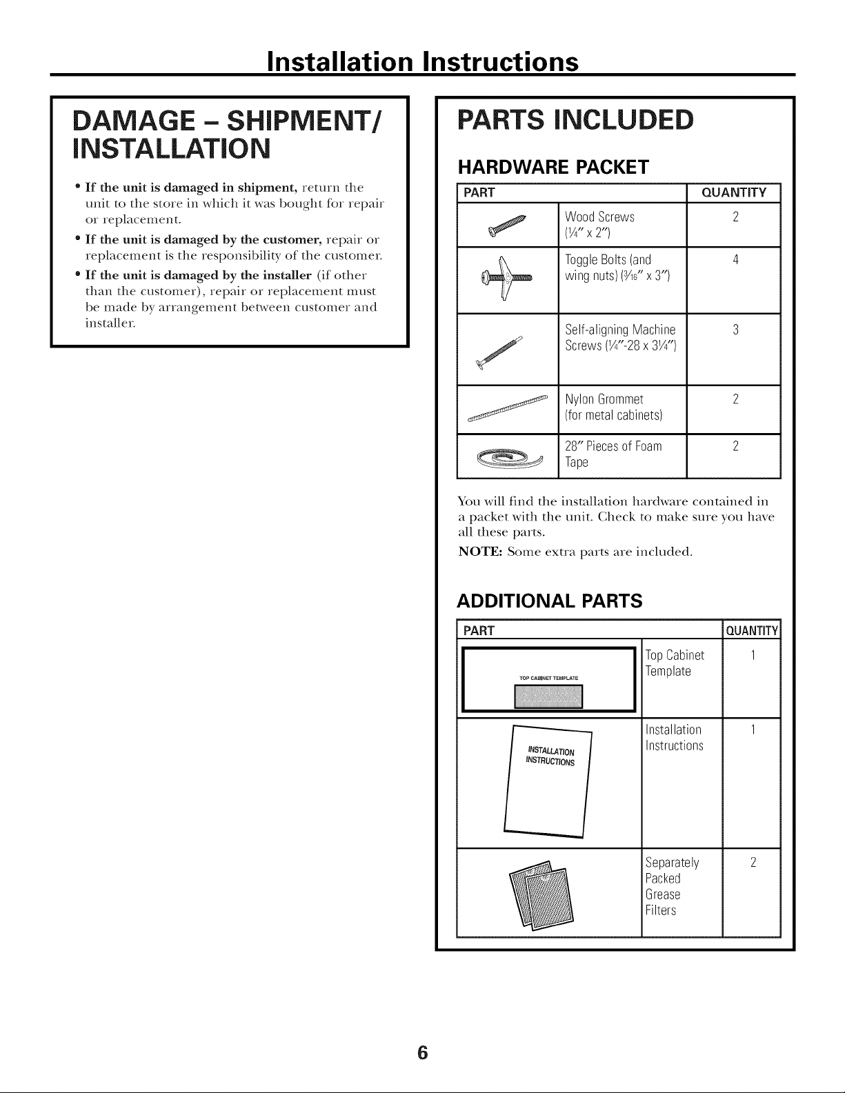
DAMAGE - SHIPMENT/
iNSTALLATiON
• If the unit is damaged in shipment, return the
unit to the store in which it was bought for repair
or replacement.
• If the unit is damaged by the customer, repair or
replacement is the responsibility of the customer
" If the unit is damaged by the installer (if other
than the customer), repair or replacement must
be made by arrangement bet_,veen customer and
installer
PARTS INCLUDED
HARDWARE PACKET
PART QUANTITY
WoodScrews 2
(¼"x2")
wing nuts)(_6" x3")
ToggleBolts(and 4
Self-aligningMachine 3
J Screws(X"-28x 3X")
j NylonGrommet 2
You will find the installation hardware contained in
a packet with the unit. Gheck to make sure you have
all these parts.
NOTE: Some exua parts are included.
(formetalcabinets)
28" Piecesof Foam 2
Tape
ADDITIONAL PARTS
PART
TopCabinet
Template
Installation
Instructions
Separately
Packed
Grease
Filters
QUANTITY
1
6
Page 7
Installation Instructions
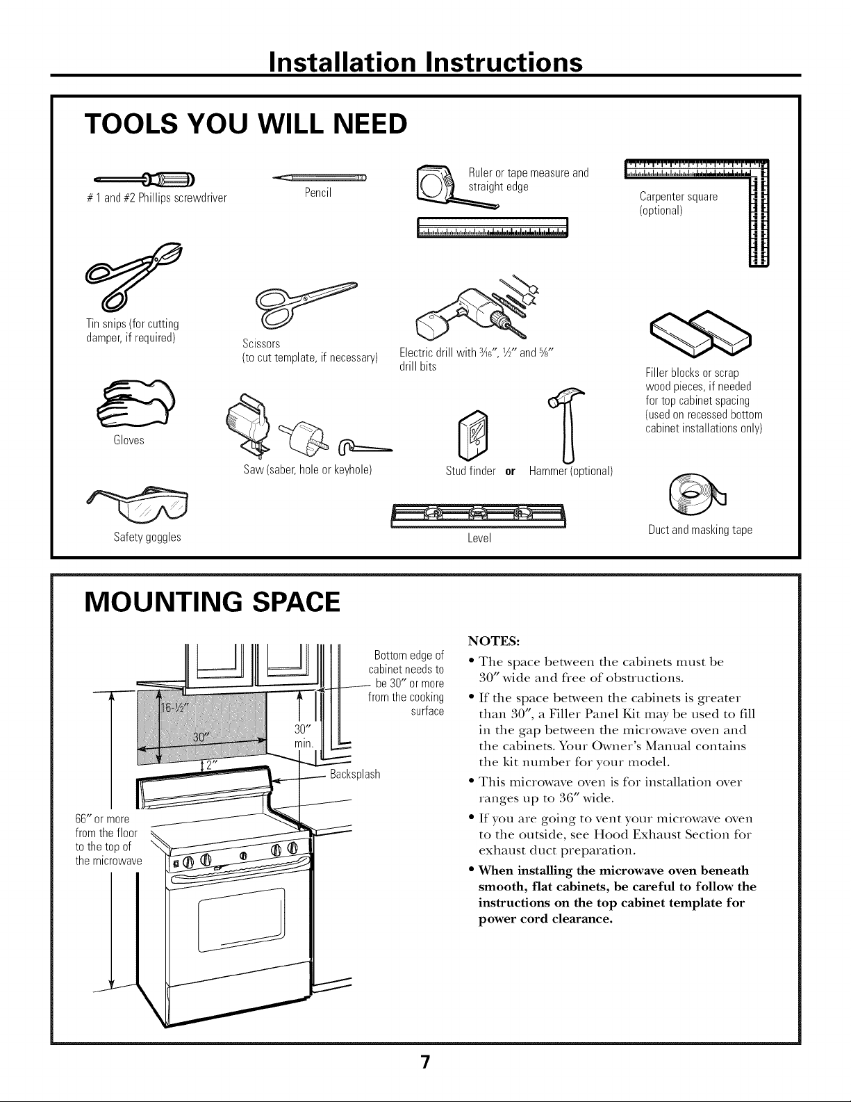
TOOLS YOU WILL NEED
# 1 and#2 Phillipsscrewdriver
Tinsnips(forcutting
damper,if required)
Gloves
Scissors
(tocuttemplate,if necessary)
Saw(saber,holeor keyhole)
Pencil
Ruleror tapemeasureand
t edge
Electricdrill with s_s',Y2"and%"
drill bits
8
Studfinder er
Hammer (optional)
Carpentersquare
(optional)
Fillerblocksor scrap
woodpieces,if needed
fortopcabinetspacing
(usedonrecessedbottom
cabinetinstallationsonly)
Safety goggles
MOUNTING SPACE
66" or more
from the floor
to the top of
the microwave
Bottomedgeof
cabinetneedsto
from thecooking
Backsplash
be30" or more
surface
Level
NOTES:
• The space between the cabinets must be
• 0 wide and free of obstructions.
• If the space between the cabinets is greater
than 30", a Fillet Panel Kit may be used to fill
in the gap between the microwave oven and
the cabinets. Your Owner's Manual contains
the kit number for your model.
• This microwave oven is for installation over
ranges tap to 36" wide.
• If you are going to vent your microwave oven
to the outside, see Hood Exhaust Section for
exhaust duct preparation.
• When installing the microwave oven beneath
smooth, flat cabinets, be careful to follow the
instructions on the top cabinet template for
power cord clearance.
Duct and masking tape
\
7
Page 8
Installation Instructions
[ PLACEMENT OF THE MOUNTING PLATE
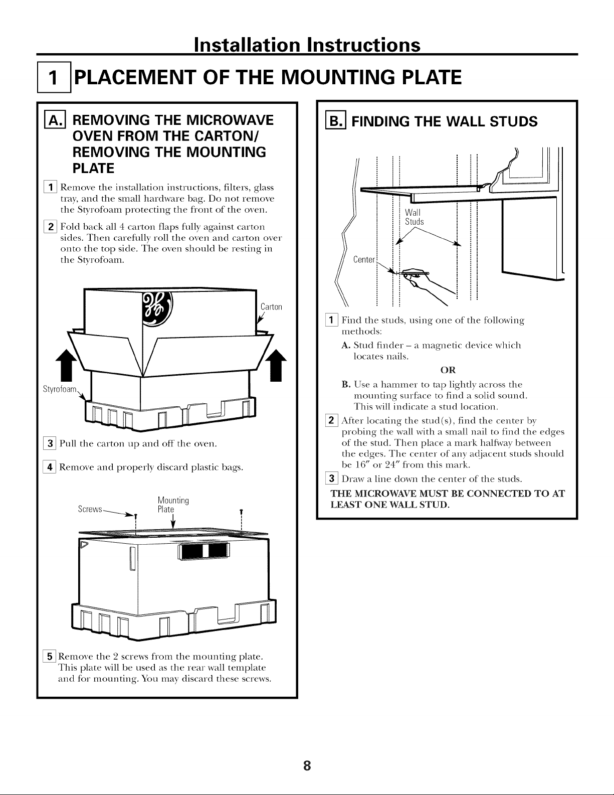
REMOVING THE MICROWAVE
OVEN FROM THE CARTON/
REMOVING THE MOUNTING
PLATE
[]Remove the installation insttuctions, filtms, glass
t_ay, and the small hardware bag. Do not temove
the Stytofoam protecting the flont of the oven.
[] Fold back all 4 catton flaps fully against carton
sides. Then carefltlly roll the oven and catton over
onto the top side. The oven should be resting in
the Styrofoam.
[]Pull the carton tap and off the oven.
[] Remove and properly discard plastic bags.
Mounting
Plate
T
I-_ FINDING THE WALL STUDS
Wall
= Studs
_Find the studs, using one of the following
methods:
A. Stud finder - a magnetic device which
locates nails.
OR
B. Use a hammer to mp lighdy across the
mounting surface to find a solid sound.
This will indicate a satd loca6on.
After locating the stud(s), find the center by
probing the wall with a small nail to find the edges
of the stud. Then place a mark half\,vay between
the edges. The center of any adjacent surds should
be 16" or 24" fiom this mark.
_Draw a line down the center of the studs.
THE MICROWAVE MUST BE CONNECTED TO AT
LEAST ONE WALL STUD.
_ Remove the 2 sctews fiom the mounting plate.
This plate will be used as the rear wall template
and for mounting. You may discard these screws.
8
Page 9

Installation Instructions
DETERMINING WALL PLATE LOCATION UNDER YOUR CABINET
Plate position - beneath flat bottom
cabinet
• °.,,, .......... ,,,,,
.o
*÷
÷%
"%
MountingPlateTabs
At least 30", up to 36"
the CabinetBottom
Plate position - beneath framed recessed
cabinet bottom
MountingPlateTabs
Touchingthe Back
Frame
L
ii
30" toCooktop
Plate position - beneath recessed bottom
cabinet with front overhang
MountingPlatewith
TabsBelowCabinet
BottomtheSame
Distanceas the Front
OverhangDepth
..
\
II
II
30" to Cooktop
÷
Your cabinets may have decorative trim that interferes
with the microwave installation. Remove the decorative
trim to install the microwave properly and to make it
level•
THE MICROWAVE MUST BE LEVEL.
Use a level to make sure the cabinet bottom is level.
If the cabinets have a flont overhang only, with no
back or side flame, install the mounting plate down
the same distance as the flont overhang depth. This
will
keep the microwave level.
[]
Measure the inside depth of the flont overhang.
%
Draw a horizontal line on file back wall an equal
distance below the cabinet bottom as the inside
depth of the flont overhang.
%
For this type of installation with flont overhang only,
align the mounting robs with tiffs horizontal line, not
touching the c_fl)inet bottom as described in Step D.
9
Page 10

Installation Instructions
ALIGNING THE WALL PLATE
[ DrawaVertical
I
, LineonWall
I-<----fromCenterof
I •
I TopCabinet
I
1'
CAUTION: Wear gloves
to avoid cutting fingers on
sharp edges.
[]Draw a vertical line on file wall at the center of the
30" wide space.
[]Use the mounting plate as the template fox the tear
waU. Place the mounting plate on tim waU, making
sure that the tabs ate touching the bottom of the
cabinet. Line up the notch and center line on
the mounting plate to the center line on the wall.
[] While holding the mounting plate with one hand,
draw citcles on the wall at holes A, B, C and D
(see illusuafion above/acatal plato marked with
arrows). Four holes must be used for mounting.
HoleD I
NOTE: Holes C and D are inside area E. If neither
C nor D is in a sutd, find a sutd somewhete in area E
and draw a fifth circle to line tap with the stud. It is
impotmnt m use at least one wood screw mounted
firmly in a stud m suppott the weight of the microwave.
Set the mounting plate aside.
Drill holes on the circles. If there is a stud, drill a _X_/'
hole for wood sctews. For holes that don't line up with
a satd, drill a %" hole for toggle bolts.
NOTE: DO NOT MOUNT THE PLATE AT THIS
TIME.
10
Page 11

Installation Instructions
INSTALLATION TYPES
This microwave oven is designed for adaptation to
the following three types of ventilation:
A. Outside Top Exhaust (Vertical Duct)
B. Outside Back Exhaust (Horizontal Duct)
C. Recirculating (Non-Vented Ductless)
OUTSIDE TOP EXHAUST
(VERTICAL DUCT)
Adaptorin Placefor
/
OutsideTopExhaust
(Choose A, B or C)
NOTE: This microwave is shipped assembled for Outside
Top Exhaust (except for non-vented models). Select the
type of ventilation required for your installation and
proceed to that section.
OUTSIDE BACK EXHAUST
(HORIZONTAL DUCT)
RECIRCULATING
(NON-VENTED DUCTLESS)
11
A Gharcoal Filter Accessory
Kit is required for the non-
vented exhaust. (See your
Owner's Manual for the kit
ntltllbeI:)
Page 12

Installation Instructions
OUTSIDE TOP EXHAUST (Vertical Duct)
INSTALLATION OVERVIEW
A1. Attach Mounting Plate to Wall
A2. Piepare Top Gabinet
A3. Gheck Damper Opmation
A4. Mount Microwave Oven
A5. Adjust Exhaust Adaptor
A6. Gonnect Ductwork
I-_ ATTACH THE MOUNTING
PLATE TO THE WALL
\
Attach the plate to the wall using toggle bolts.
At least one wood screw illust be used to attach
the plate to a wall stud.
[]Remove the toggle wings flom the bolts.
_ Insert the bolts into the mounting plate
thFough the holes designated to go into drDvall
and reatmch the toggle wings to :_" onto each bolt.
====
To use toggle bolts:
Spacingfor Toggles
MoreThanWall
+l_,.[_,_Th ickness
Mounting
Plate_.
_ Place the mounting plate against the wall and
insert the toggle wings into the holes in the wall
to mount the plate.
NOTE: Before tightening toggle bolts and wood
screw, make sure the robs on the mounting plate
touch the bottom of the cabinet when pushed
flush against the wall and that the plate is properly
centered under the cabinet.
CAUTION: Be careflfl to avoid pinching fingers
between the back of the mounting plate and the wall.
_ Tighten all bolts. Pull the plate away fiom the wall
to help tighten the bolts.
Wings
BoltEnd
12
Page 13

Installation Instructions
I-_ USE TOP CABINET TEMPLATE
FOR PREPARATION OF TOP
CABINET
You need to drill holes for tile top support screws, a
hole large enough for tile power cord to fit ttlrough,
and a cutout large enough for tile exllaust adaptoL
• Read the instructions on the TOP CABINET
TEMPI ,ATE.
• Tape it underneattl tile top cabinet.
• Drill tile holes, following tile instructions on tile
TOP CABINET TEMPI,ATE.
CAUTION: Wear safety goggles when drilling holes
in tile cabinet bottom.
I-_ CHECK FOR PROPER
DAMPER OPERATION
ExhaustAdaptor
BlowerPlate
(absentonmodelsshipped
for recirculationexhaust)
Damper
I-_ MOUNT THE MICROWAVE
OVEN
FOR EASIER INSTAI,I,ATION AND PERSONAI,
SAFETY, WE RECOMMEND THAT TWO PEOPLE
INSTALL THIS MICROWAVE OVEN.
IMPORTANT: Do not grip or use handle
during installation.
NOTE: If your cabinet is metal, use tim nylon
grommet around tim power cord hole to prevent
cutting of tim cord.
NOTE: We recommend using filler blocks if the
cabinet flont hangs below the cabinet bottom shelf.
IMPORTANT: If filler blocks are not
used, case damage may occur from over
tightening screws.
NOTE: When mounting
tile microwave oven,
thread power cord
through hole in bottom of
top cabinet. Keep it tight
throughout Steps 1-3. Do
not pinch cord or lift
oven by pulling cord. "--.._{
_I,ifl tilt it
microwave,
forward, and hook
slots at back bottom
edge onto four lower
robs of mounting
plate.
Backof
Microwave
• Place tile microwave in its upright position, with the
top of tim unit facing up.
• This microwave oven may be shipped assembled for
top exhaust (adaptor installed) or for recirculadon
exhaust (adaptor absent).
• Make sure tape securing damper is removed and
damper pivots easily before mounting microwave.
• You will need to make adjusmlents to assure proper
alignment with your house exhaust duct after the
microwave is installed.
_ Rotate flont of
up against cabinet
bottom.
oven
_Insert a self-aligning screw through top center
cabinet hole. Temporarily secure the oven by
turning the screw at least two full turns after the
threads have engaged. (It will be completely
tightened later.) Be sure to keep power cord
tight. Be careful not to pinch the cord, especially
when mounting flush to bottom of cabinet.
13
Page 14

Installation Instructions
CabinetFront
CabinetBottomShelf
FillerBlock
Depth
ofCabinet
-_ Equivalentto
Recess
Self-AligningScrew
MicrowaveOvenTop
[]Attach the microwave oven to the top cabinet°
I-_ ADJUST THE EXHAUST
ADAPTOR
Open the top cabinet and adjust the exhaust adaptor
to connect to the house duct.
Backof
BlowerPlate Damper Microwave
[] Insert 2 self-aligning screws
through outer top cabinet
holes. Turn two flfll turns on
each screw.
[
[]Tighten center
screw completely.
[] Tighten the outer two screws to the top of the
microwave oven. (While tightening screws, hold
the microwave oven in place against the wall and
the top cabinet.
1400and1600Series 1800Series
Side-to-Side
Adjustment,Slidethe
ExhaustAdaptoras
Needed
I-_ CONNECTING DUCTWORK
HouseDuct
_1_ Extend the house duct down to connect to
the exhaust adaptor.
[] Seal exhaust duct joints using duct tape.
[] Install grease filters. See the Owner's Manual
packed with the microwave.
14
Page 15

Installation Instructions
OUTSIDE BACK EXHAUST (Horizontal Duct)
INSTALLATION OVERVIEW
B1. Prepare Rear Wall
B2. Attach Mounting Plate to _rall
B3. Prepare Top Cabinet
B4. Adjust Blower
BS. Mount the Microwave Oven
I-_ PREPARING THE REAR WALL
FOR OUTSIDE BACK EXHAUST
_!_ Place the mounting plate against the rear wall and
align it with the holes drilled earlier.
[] Using a pencil, put clots through holes/notches F,
G, H and I (see above illusuadon). Remove the
mounting plate and draw lines extending through
the points. This will give the location and size of the
box cutout for the rear wall duct.
[] Use a saw (saber or keyhole) to cut out the opening.
_!_ Place the microwave in its upright position with the
top of the unit facing tap.
This microwave oven is shipped assembled for top
exhaust. You will need the exhaust adaptor for
installation in the rear wall opening. To remove the
exhaust adaptor flom the microwave oven:
Remove rope securing dampm.
Lift off the
Remove and blower plate
save screw _ _ and attached
• " uamper
that holds "_, / adaptor flom
blower plate ,, ./ the microwave.
to microwave ..... _..., ..,_
......... -"" _ Microwave
_ Slide exhaust adaptor to one side and remove it.
15
Page 16

Installation Instructions
_ REPARING THE REAR WALL
FOR OUTSIDE BACK EXHAUST
(continued)
House
Duct
Damper Swings
[]Fit the exhaust adaptor into the house duct as
shown. Make sure the exhaust adaptor (with the
damper) is squared up in the house duct and lines
up with the holes in the mounting plate.
[]Remove the paper flom the stick), side of the 28"
foam tape. Press the sock), side onto the face of the
exhaust adaptoL (Don't stretch the foam tape.)
Damper Hinge On Top
To use toggle bolts:
Spacingfor TogglesMore
-_]_-_i_-- ThanWall Thickness
Mounting
Plate
ToggleWings
O
BoltEnd
_ Place the mounting plate against the wall and
insert the toggle wings into the holes in the wall to
mount the plate.
NOTE: Before 0gbtening toggle bolts and wood
screw, make sure the robs on the mounting plate
touch the bottom of the cabinet when pushed flush
against the wall and that the plate is properly
centered under the cabinet.
CAUTION: Be careflll to avoid pinching fingers
between the back of the mounting plate and the wall.
_ Tighten all bolts. Pull the plate away flom the wall
to help tighten the bolts.
/I)7 ount,no/ II
J _ Plate iDU
°o*__Jl_°, °° °, °° °, "°°o',°° "°°°°o'° °°°o °°°o *°°°
t_ t"-I t-'-t t"l
_Atmch the other 28" foam rope to the flont of
the mounOng plate around both of the exhaust
openings where it will touch the microwave.
I-_ ATTACH THE MOUNTING
PLATE TO THE WALL
i
Attach the plate to the wall using toggle bolts.
At least one wood screw must be used to attach
the plate to a wall stud.
Remove the toggle wings flom the bolts.
_ Insert the bolts into the mounting plate through
the holes designated to go into drywall and reattach
the toggle wings to :X" onto each bolt.
I-_ USE TOP CABINET TEMPLATE
FOR PREPARATION OF TOP
CABINET
You need to drill holes for the top support screws and
a hole large enough for the power cord to fit tllrough.
%
• Read the instrucOons on the TOP CABINET
TEMPI_ATE.
• Tape it underneath the top cabinet.
• Drill the holes, following the instruc0ons on the
TOP CABINET TEMPLATE.
CAUTION: Wear safety goggles when drilling holes
in the cabinet bottom.
16
Page 17

Installation Instructions
ADAPTING MICROWAVE
BLOWER FOR OUTSIDE
BACK EXHAUST
_i_ Remove and save screw that holds blower motor
to IIllC Iowave.
BlowerMotor
otlt
[] Careflllly tile blower unit. Tile wires
will extend far enough to allow you to adjust tile
blower unit.
pull
Backof
Microwave
-_ BlowerMotor
- "_--- Screw
[]Roll tile blower unit 90 ° so that fan blade
openings are facing out tile back of tile
IIlicrowave.
BeforeRolling
Backof
Microwave
_ Place tile blower unit back into tile opening.
End
After Rolling
I Backof
EndA
Microwave
End
[] Rotate blower unit counterclockwise 180 °.
BeforeRotation After Rotation
Microwave Microwave
[]Gently tile wires flom tile
Reroute tile wires through grooves on other side
of tile blower unit.
ielilove
BeforeRerouting After Rerouting
grooves.
CAUTION: Do not pull or stretch the blower
unit wiring. Make sure the wires are not
pinched.
NOTE: The blower unit exhaust
openings should match exhaust
openmgs on rear of microwave oven.
Secure tile blower unit to tile microwave with
tile screw from Step 1.
BlowerPlate
1
I
_ Replace tile blower in tileplate position
as before with tile screw.
Backof
Microwave
BlowerMotor
Screw
same
WiresRoutedThroughRightSide WiresRoutedThroughLeftSide
17
Page 18

Installation Instructions
I-_ MOUNT THE MICROWAVE
OVEN
;TJ J
FOR EASIER INSTAI,I,ATION AND PERSONAL
SAFETY, WE RECOMMEND THAT TWO PEOPLE
INSTALL THIS MICROWAVE OVEN.
IMPORTANT: Do not grip or use handle
during installation.
NOTE: If your cabinet is metal, use tim nylon
grommet around the power cord hole to prevent
cutting of the cord.
NOTE: We recommend using fillet blocks if the
cabinet flont hangs below the cabinet bottom shelf.
IMPORTANT: If filler blocks are not
used, ease damage may occur from over
tightening screws.
CabinetFront
CabinetBottomShelf
FillerBlock
T quivalent
to Depth
ofCabinet
Recess
Self-AligningScrew
MicrowaveOvenTop
_ Attach the microwave oven to the top cabinet.
Insert 2 self-aligning screws
through outer top cabinet
holes. Turn two fltll turns on
each screw.
NOTE: When mounting
the Illicrowave oven,
thread power cord
through hole in bottom of
top cabinet. Keep it tight
throughout Steps 1-3. Do
not pinch cord or lift
oven by pulling cord.
[]Lift microwave, tilt it
forward, and hook
slots at back bottom
edge onto four lower
robs of mounting
plate.
[]Rotate fiont of
up against cabinet
bottom.
oven
[]Insert a self-aligning screw through top center
cabinet hole. Temporarily secure the oven by
turning the screw at least two full turns after the
threads have engaged. (It will be completely
6ghtened later.) Be sure to keep power cord
tight. Be careful not to pinch the cord, espedally
when mounting flush to bottom of cabinet.
_ Tighten center
screw completely.
[] Tighten the outer two screws to the top of the
microwave oven. (While tightening screws, hold
the microwave oven in place against the wall and
the top cabinet.'
1400and1600Series
_ Install grease filters. See the Owner's Manual
packed with the microwave.
1800Series
18
Page 19

Installation Instructions
RECIRCULATING
INSTALLATION OVERVIEW
C1. Attach Mounting Plate to Wall
C2. Prepare Top Cabinet
C3. Check Microwave Assembly
C4. Adjust Blower
C5. Mount the Microwave Oven
C6. Install Charcoal Filter
I-_ ATTACH THE MOUNTING
PLATE TO THE WALL
(Non-Vented Ductless}
_ Place the mounting plate against the wall and
insert the toggle wings into the holes in the wall
to I_lotlnt the plate.
NOTE: Before tightening toggle bolts and wood
screw, make sure the robs on the mounting plate
touch the bottom of the cabinet when pushed flush
against the wall and that the plate is properly
centered under the cabinet.
CAUTION: Be carefid to avoid pinching fingers
between the back of the mounting plate and the wall.
===
_ Tighten all bolts. Pull the plate away flom the wall
to help tighten the bolts.
\
Attach the plate to the wall using toggle bolts.
At least one wood screw illtlst be used to attach
the plate to a wall stud.
[]Remove the toggle wings flom the bolts.
[]Insert the bolts into the mounting plate through
the boles designated to go into drDvall and
reatmch the toggle wings to SA" onto each bolt.
To use toggle bolts:
Spacingfor Toggles
MoreThanWall
+l_.i_---Thickness
Mounting
Plate
Wings
BoltEnd
USE TOP CABINET TEMPLATE
FOR PREPARATION OF TOP
CABINET
You need to drill holes for the top support screws and
a hole large enough for the power cord to fit through.
• Read the instructions on the TOP CABINET
TEMPI_ATE.
• Tape it underneath the top cabinet.
• Drill the holes, following the instructions on the
TOP CABINET TEMPLATE.
CAUTION: Wear safeb, goggles when drilling holes
in the cabinet bottom.
19
Page 20

Installation Instructions
CHECK MICROWAVE ASSEMBLY
Exhaust Adaptor (absent
on models shipped for
recirculation exhaust)
Backof
,,
• Place the microwave in its upright position, with the
top of the unit facing up.
• The microwave oven may be shipped assembled for
top exhaust (adaptor installed) or for recirculation
exhaust (adaptor absent).
• If the microwave was shipped for recirculafion
exhaust, skip to (;5. If shipped for top exhaust,
proceed with (;4.
ADAPTING MICROWAVE
BLOWER FOR RECIRCULATION
_ Careflflly pull out the blower unit. The wires
will extend far enough to allow you to adjust the
blower unit.
_Roll the blower unit 90 ° so that fan blade openings
are facing toward the flont of the microwave.
[] Remove . _ Denper [] I,ifl off the
and save , blower plate
screw that and attached
holds blower" adaptor from
plate to the microwave.
microwave. [
Backof
_-- Microwave "
_ Slide exhaust adaptor to one side and remove it.
NOTE: The exhaust adaptor with damper is not
needed for recirculating models. You may want to
save them for possible furore use.
_ Remove and the that holds the blower
motor to the microwave.
_ BlowerPlate
save screw
R011
NOTE: Make sure wires remain routed in the
grooves of the motor flame.
_11_ Backof
€_ _- Microwave
11_ "----. _. BlowerMotor
""q_-- Screw
20
Page 21

Installation Instructions
ADAPTING MICROWAVE
BLOWER FOR
RECIRCULATION (continued)
]Place tile blower unit back into tile opening.
CAUTION: Do not pull or stretch the blower unit
wiring, Make sure the wires are not pinched,
]Secure blower unit to microwave with the screw
removed in Step 4.
Replace blower plate with the screw removed in
Step l.
T
I
_.___ Backof
Microwave
NOTE: When mounting
tile microwave oven,
thread power cord
through hole in bottom of
top cabinet. Keep it fight
throughout Steps 1-3. Do
not pinch cord or lift
oven by pulling cord.
[]Lift microwave, tilt it
forward, and hook
slots at back bottom
edge onto four lower
tabs of mounting
plate.
/
_ Rotate flont of oven
up against cabinet
bottom.
_ Insert a self-aligning screw through top center
cabinet hole. Temporarily secure the oven by
turning the screw at least two full turns after the
threads have engaged. (It will be completely
6ghtened later.) Be sure to keep power cord
tight. Be careful not to pinch the cord, especially
when mounting flush to bottom of cabinet.
MOUNT THE MICROWAVE
OVEN
FOR EASIER INSTAI,I,ATION AND PERSONAL
SAFETY, WE RECOMMEND THAT TWO PEOPLE
INSTALL THIS MICROWAVE OVEN.
IMPORTANT: Do not grip or use handle
during installation.
NOTE: If your cabinet is metal, use the nylon
grommet around the power cord hole to prevent
cutting of the cord.
NOTE: We recommend using fillet blocks if the
cabinet flont hangs below the cabinet bottom shelf.
IMPORTANT: If filler blocks are not used,
case damage may occur from over tightening
screws.
CabinetFront
CabinetBottomShelf
FillerBlock
-3_oEquivalentto Depth
f CabinetRecess
Self-AligningScrew
MicrowaveOvenTop
_Attach the microwave oven to the top cabinet.
21
Page 22

Installation Instructions
MOUNT THE MICROWAVE
OVEN (continued}
[] Insert 2 self-aligning screws
through outer top cabinet
holes. Turn two fldl turns oil
each screw.
[] Tighten center
screw completely.
[] Tighten the outer two screws to the top of the
microwave oven. (While tightening screws, hold
the microwave oven in place against the wall and
the top cabinet.'
1400and 1600Series
1800Series
iNSTALLiNG THE
CHARCOAL FILTER
[] On 1400 and 1600 Series models, remove screws
on flont of grille using a #1 Phillips screwdriveL
On 1800 Series models, remove screws on top
flont of grille using a #2 Phillips screwdriver.
_Open the door.
Remove the grille.
Charcoal
_ Install the charcoal filter. When properly
the wire mesh of the filter should be visible from
the f_ont.
Replace the grille and the screws.
_ Close the door.
1400SeriesModel 1600and1800SeriesModel
installed,
[] Install grease filters. See the Owner's Manual
packed with the microwave.
I
Insertmesh-sidedown
22
Insertmesh-sideup
Page 23

Installation Instructions
BEFORE YOU USE YOUR MICROWAVE
='iT] Make sure the microwave oven has been
installed according to instructions.
_ emove all packing material flom the
microwave oven.
'_-1 Install turntable and ring in cavity.
I
-_7] Read the Owner's Manual.
[=_ KEEP INSTAI,LATION INSTRUCTIONS
FOR THE LOCAL INSPECTOR'S USE.
I
--_ Replace house fuse or mrn breaker back on.
'57] lug power cord into a dedicated 15 to 20 amp
electrical outlet.
F
t
F
.I
23
Page 24

t 164D3370P12949-40134-2 ]
06-011 JR Printed in Korea
 Loading...