

Page 1
Installation
Abovethe
Instructions
I Questions? Carl 800-GE-CARES (800-432-2737) orvisit ore"Websit_ at: www.GEAppliances.com I
CooktopOven
JVM1490,SCA1000andSCA1001
BEFORE YOU BEGIN
Read these instructions completely and carefully.
• IMPORTANT - Savethese
instructions for local inspector's use.
• IMPORTANT - Obsc_-_oall
governing codes and ordinances.
• Note to Installer _ Be sure to leavethese
instructions with the Consumer.
• Note to Consumer - Keep these
instructions for future reference.
• Skill level - Installation of this appliance requires
basic mechanical and electrical skills.
• Proper installation is the responsibility of the installm:
• Product failure due to improper installation is not
covered under the Warranty.
I!! Ii
LA SECCION EN ESPAI_IOL
EMPIEZA EN LA PAGINA 25.
READ CAREFULLY.
KEEP THESE INSTRUCTIONS.
Page 2
Installation Instructions
CONTENTS
General information
Important Safety Instructions .................................. 3
Electrical Requirements .......................................... 3
Hood Exhaust ...................................................... 4, 5
Damage - Shipment/Installation .............................. 6
Parts Included .......................................................... 6
Tools You Will Need ................................................ 7
Mounting Space ...................................................... 7
Step-by-step installation guide
Placement of Mounting Plate ............................ 8-10
Rcmox_mg the Mounting Plate ...................... 8
Finding tile Wall Studs .................................. 8
Determining Wall Plate Location .................. 9
] Recirculating ........................................ 19-22
Attach Mounting Plate to Wall ............ 19
Preparation of Top Cabinet ................ 19
Adapting Blower
for Recirculation .......................... 20, 21
Mount the Oven ............................ 21, 22
Installing the Charcoal Filter .............. 22
Before You Use Your Oven .................................. 23
Secci6n en Espafiol ........................................ 2547
Aligning the Wall Plate ................................ 10
Installation Types .............................................. 11-22
_] Outside Top ............................
Attach Mounting Plate to Wall ............ 12
Preparation of Top Cabinet ................ 13
Checking for Proper Damper
Exhaust
12-14
Operation ............................................ 13
Mount the Oven ............................ 13, 14
Adjust the Exhaust Adaptor ................ 14
Connecting Ductwork .......................... 14
_] Outside Back Exhaust 15-18
Preparing Rear Wall for
Outside Back Exhaust .......................... 15
Attach Mounting Plate to Wall ...... 15, 16
Preparation of Top Cabinet ................ 16
Adapting Blower for Outside
Back Exhaust .................................... 16, 17
Mount the Oven .................................. 18
2
Page 3
Installation Instructions
IMPORTANT SAFETY INSTRUCTIONS
This product requires a three-prong grounded
outlet. The installer must peribrm a ground continuity
check on the power outlet box beibre beginning the
installation m insure that tile outlet box is properly
grounded, if not properly grounded, or if the
outlet box does not meet electrical requirements
noted (under ELECTRICAL REQUIREMENTS),
a qualified electrician should be employed to
correct any deficiencies.
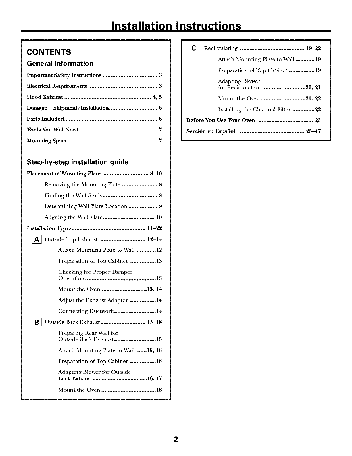
CAUTION: For personal
safety, remove house fuse
or open circuit breaker
before beginning installation
to avoid severe or fatal
shock injury.
CAUTION: For personal safety, the momaling surface
must be capable of supporting the cabinet load, ha
addition to the added weight of this 63-85 pound
product, plus additional oven loads of up to 50 pounds
or a total weight of 113-135 pounds.
CAUTION: For personal safety, this product cannot
be installed ha cabinet arrangements such as an island or
a peninsula. It must be mounted to BOTH a top cabinet
AND a wall.
You should have the wall receptacle and circuit checked
by a qualified electricima to make sure the receptacle is
properly grounded.
Where a standard two-prong wall receptacle is
encomatered, it is very important to have it replaced
with a properly grounded three-prong wall receptacle,
installed by a qualified electrician.
DO NOT, UNDER ANY CIRCUMSTANCES, CUT,
DEFORM, OR REMOVE ANY OF THE PRONGS
FROM THE POWER CORD. DO NOT USE WITH
AN EXTENSION CORD.
ELECTRICAL
REQUIREMENTS
Product rating is 120 volts AC, 60 Hertz, 15 amps, and
1.70 kilowatts. This product must be connected to
a supply circuit of the proper voltage and fi'equency.
Wire size must conform to the requirements of the
National Electrical Code or the prevailing local code
for this kilowatt rating. The power supply cord and
plug should be brought to a separate 15 to 20 ampere
branch circuit single grounded outlet. The outlet box
should be located in the cabinet above the oven. The
outlet box and supply circuit should be installed by
a qualified electrician and conform to the National
Electrical Code or the prevailing local code.
NOTE: For easier installation and personal safety, it is
recommended that two people install this product.
IMPORTANT--PLEASE READ CARF_UIIY. FOR
PERSONAL SAFETY, THIS APPLIANCE MUST BE
PROPERLY GROUNDED TO AVOID SEVERE OR
FATAL SHOCK.
The power cord of this appliance is equipped with
a three-prong (grounding)
plug which mates with
a standard three-prong
(grounding) wall receptacle
to minimize the possibility
of electric shock hazard
from this appliance.
insureproper
groundexists
beforeuse
3
Page 4
Installation Instructions
HOOD EXHAUST
NOTE: Read these next two pages only if you plan to vent your exhaust to the outside.
If you plan to recirculate the air back into the room, proceed to page 6.
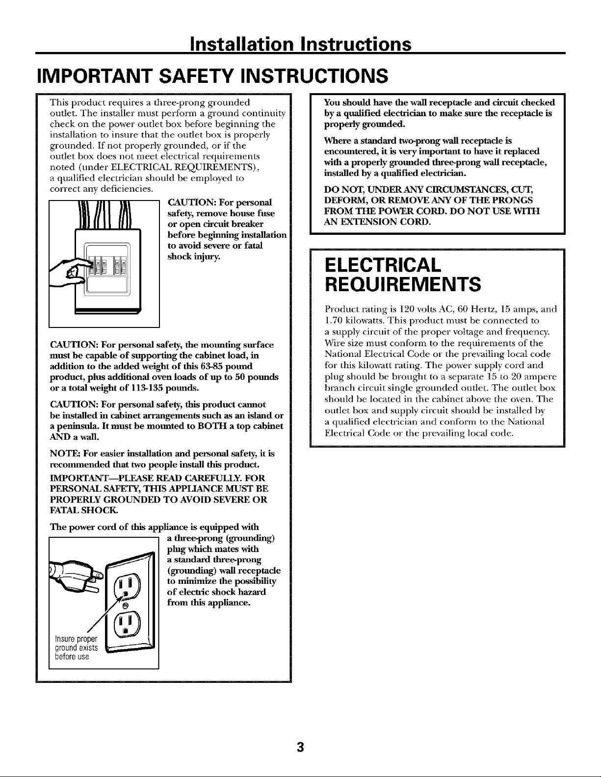
OUTSIDE TOP EXHAUST (EXAMPLE ONLY)
The fbllowing chart describes an example of one possible
ductwork installation.
EQUIVALENT NUMBER EQUIVALENT
DUCT PIECES LENGTH x USED = LENGTH
12Ft.StraightDuct 12Ft. x (1) = 12Ft.
RoofCap 24 Ft. x (1) = 24 Ft.
(6" Round)
TransitionAdaptor*
Rectangular4o-Round 5Ft. x (1) = 5Ft.
Equivalentlengthsofductpiecesarebasedonactualtests and
reflectrequirementsforgoodventingperformancewith anyventhood.
*IMPORTANT: If a rectangular-to-round transition adaptor is used, the bottom corners of the damper
will have to be cut to fit, using the tin snips, in order to allow fi'ee movement of the damper.
OUTSIDE BACK EXHAUST (EXAMPLE ONLY)
The following chart describes an example of one possible
ductwork installation.
EQUIVALENT NUMBER EQUIVALENT
_,.....__ Wall Cap 40Ft. x (1) 40Ft.
DUCT PIECES LENGTH* x USED = LENGTH
3 Ft.StraightDuct 3Ft. x (1) 3Ft.
37g"x 10"Rectangular)
Total Length = 41 Ft.
90° Elbow 10Ft. x (2) 20Ft.
Equivalentlengthsof ductpiecesarebasedonactualtests and
reflectrequirementsforgoodventingperformancewith anyventhood.
NOTE: For back exbaust, care sbould be taken to align exhaust witb space between studs, or wall should be prepared
at the time it is constructed by leaving enough space between the wall studs to accommodate exhaust.
Total Length = 63 Ft,
4
Page 5
Installation Instructions
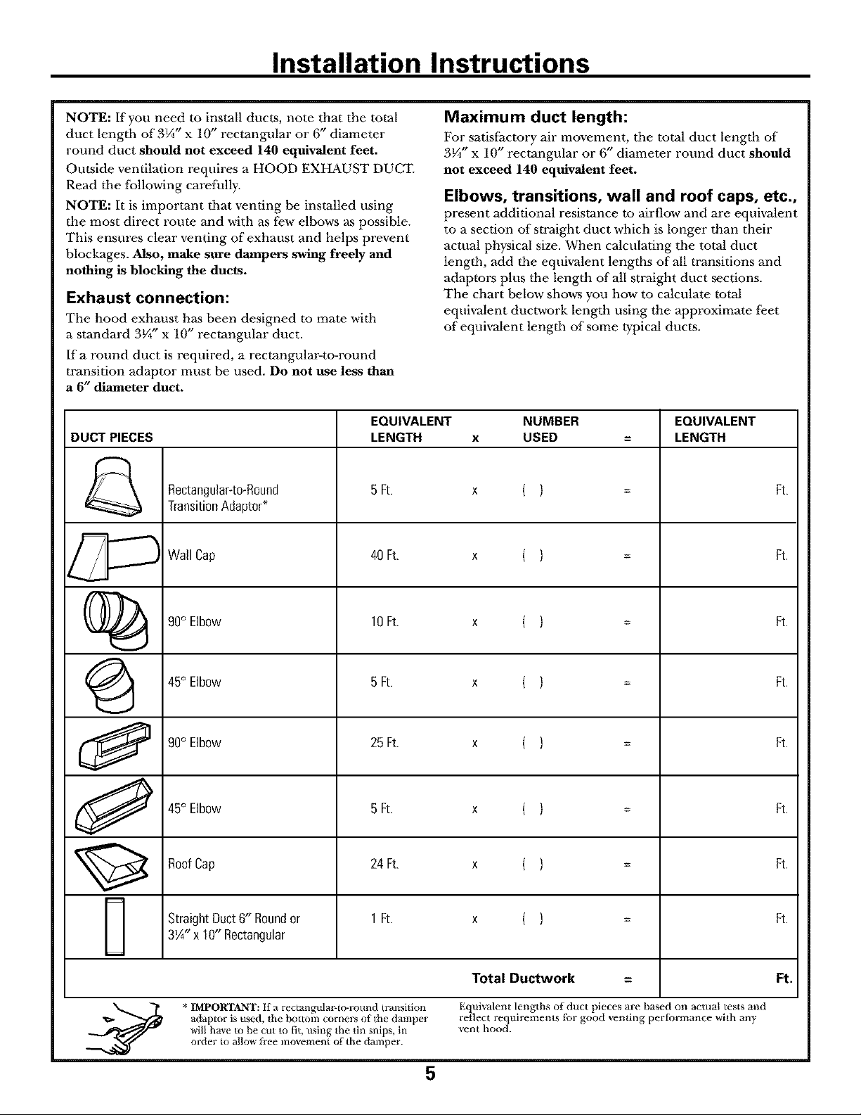
NOTE: If you need to install ducts, note that the total
duct lengtb of 3¼" x 10" rectangular or 6" diameter
round duct should not exceed 140 equivalent feet.
Outside ventilation requires a HOOD EXHAUST DUCT.
Read tile following carefully.
NOTE: It is important tbat venting be installed using
the most direct route and with as few elbows as possible.
This ensures clear venting of exhaust and helps prevent
blockages. Also, make sure dampers swing freely and
nothing is blocking the ducts.
Exhaust connection:
The hood exhaust has been designed to mate witb
a standard 3¼" x 10" rectangular duct.
If a round duct is required, a rectangular-to-round
transition adaptor must be used. Do not use less than
a 6" diameter duct.
EQUIVALENT NUMBER EQUIVALENT
DUCT PIECES LENGTH x USED = LENGTH
Rectangular_to-Round 5 Ft. x ( ) Ft.
TransitionAdaptor*
Maximum duct length:
For satisfhctory air movement, the total duct length of"
3¼" x 10" rectangular or 6" diameter round duct should
not exceed 140 equivalent feet.
Elbows, transitions, wall and roof caps, etc.,
present additional resistance to airflow and are equivalent
to a section of straight duct which is longer than their
actual physical size. When calculating the total duct
lengtb, add tbe equivalent lengtbs of all transitions and
adaptors plus tbe length of all straight duct sections.
The chart below shows you how to calculate total
equivalent ductwork length using the approximate feet
of equivalent lengtb of some typical ducts.
Wall Cap 40 Ft. x ( ) Ft.
(i)_ 9O°EIbow lOFt. x ( ) Ft.
(_ 45° Elbow 5 Ft. x ( ) Ft.
90° Elbow 25 Ft. x ( ) Ft.
45° Elbow 5 Ft. x ( ) Ft.
RoofCap 24 Ft. x ( ) Ft.
StraightDuct6" Roundor 1 Ft. x ( ) Ft.
3¼" x 10" Rectangular
Total Ductwork = Ft.
adaptor is used, the bottom cornm_ of the damper reflect requirements for good venting performance with any
_'iU ha_e to be cut to fit, t_sing the tin snips, in _ent hood.
* IMPORTANT: if a iectangtflm_to-round transition Equiwflent lengths of duct pieces are based on actual tests and
order to aUo_ fi'ee inovement of the damper.
5
Page 6
Installation Instructions
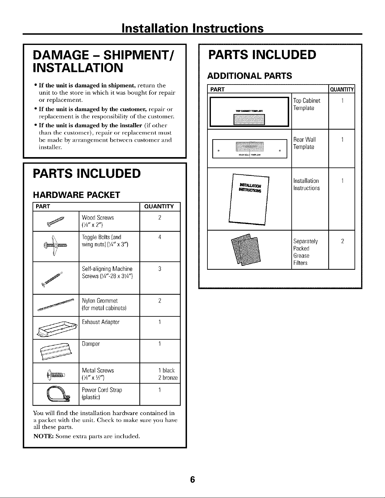
DAMAGE - SHIPMENT/
INSTALLATION
" If the unit is damaged in shipment, return tile
unit m the store in which it was bought J[br repair
or replacement.
" If the unit is damaged by the customer, repair or
replacement is the responsibility of the customer.
" If the unit is damaged by the installer (if other
than the customer), repair or replacement must
be made by arrangement between customer and
installmz
PARTS INCLUDED
HARDWARE PACKET
PART QUANTITY
WoodScrews 2
(I/4_1 X 2")
PARTS INCLUDED
ADDITIONAL PARTS
PART
TopCabinet
_ _msEr w
L
Template
RearWall
Template
Installation
Instructions
QUANTITY
1
I\ Togg{eBolts(and 4
_ wingnuts)(_A"x 3")
Se{f-a{igningMachine 3
Screws(IA"_28x 3_A")
NylonGrommet 2
(formetalcabinets)
ExhaustAdaptor 1
_ Damper 1
Metal Screws 1black
(IA"x *A") 2bronze
PowerCordStrap 1
(plastic)
You will find the installation hardware contained in
a packet with the unit. Check to make sure you have
all these parts.
NOTE: Some extra parts are included.
®
Sepamtely
Packed
Grease
Filters
6
Page 7
Installation Instructions
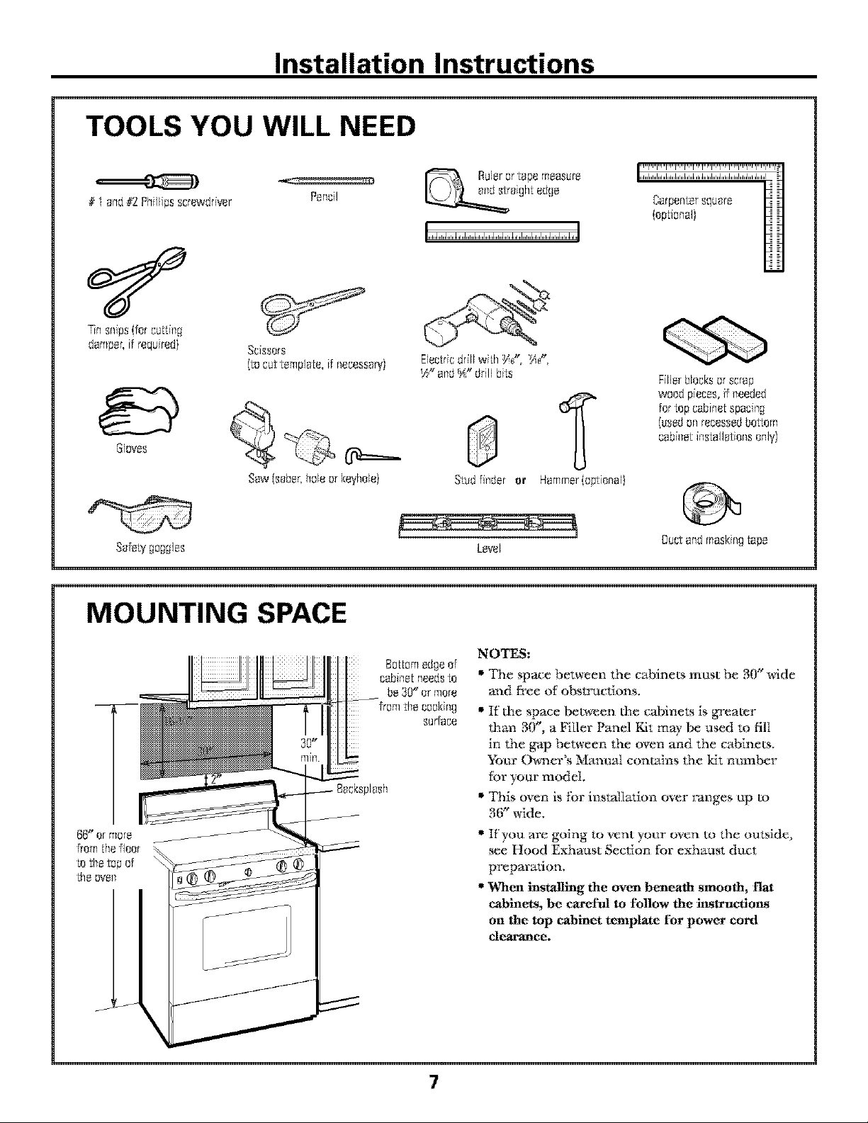
TOOLS YOU WILL NEED
# I o_d#2 Phifiipsscrewdriver
_n snips {fer [:u[[ill[_
_cissers
Pencil
Ruleror 1:apemeasure
figh[ edge
{ep[i_nal)
Electricdrill wi[h :_(", _i(',
_" a_d_" driftbi[s Fillerblocks_r scrap
fer [epcabine[spacfl_g
Gloves
Sofe_goggles
MOUNTING SPACE
plosh
cebfl_etfl_stallotiensonly)
weedpieces,if ileeded
(usedonrecessedbottom
Studffl_der or
@
Level
NOTES:
" _I_e space between dm cabinets must be NY" wide
m_d tYee of' obstructions.
" If the space between the cabinets is greater
than BO", a Filler Panel Kit may be used to fill
in ti_e g_ap between lhe oven and the cabinets.
}%ar (_cr's ManuN contains the kit number
tbr your model.
• This oven is tbr installation over ranges tip m
36" wide,
" If you are going m vent your oven m lhe outside,
see Hood Exhaust Section tbr exhaust duct
preparation.
•When installing the oven beneath smooth, flat
cabinets, be care[_l to follow the instruc_ons
on the top cabinet template For power cord
clearance.
Ductandmaskingtape
7
Page 8
Installation Instructions
PLACEMENT OF THE MOUNTING PLATE
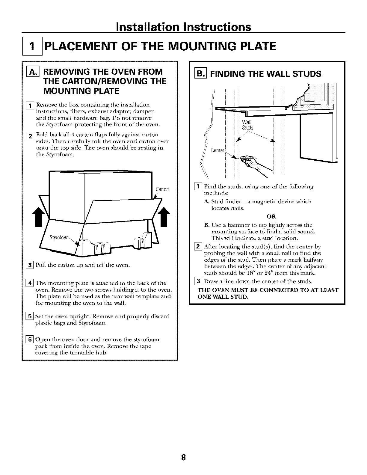
[] REMOVING THE OVEN FROM
THE CARTON/REMOVING THE
MOUNTING PLATE
[]Remove the box conudning the instMlation
instructions, filters, exhaust adaptm; damper
and the small hardware bag. Do not remove
the Styrofbam protecting the fl:ont of the oven,
[] Fold back all 4 carton flaps fully against c_u'ton
sides. Then carefully roll 0_e oven and era:ton over
onto the top side. The oven should be resting in
the Styrofbam.
[] Pull Ihe car_on up and off the oven.
[] The motmting plate is attached to the back of the
oven. Remove the two screws holding it to the oven,
The plate will be used as the rear wall template and
fbr mounting the oven to the wall.
[-_ FINDING THE WALL STUDS
[] Find the studs, using one of the fbllowing
methods:
A. Stud finder - a magnetic device which
locates nails.
OR
B T
• Use a hmnmer to tap lightly across the
mounting surfhce to find a solid sound,
This will indicate a stud location,
[] After locating Ihe stud(s), tind the center by
probing Ihe v#all with a sm_dl nail to find the
edges of the stud, Then place a mark halgva)
between the edges. The center of any _ljacent
studs should be 16_"or- 24" fi'om Ibis mark,
]Draw a line down the center of the studs,
THE OVEN MUST BE CONNECTED TO AT LEAST
ONE WALL STUD•
[] Set the oven upright. Remove and properly discard
plastic bags and Styrofbwn.
[] Open the oven door and remove 1he st}rotbarn
pack Dora inside the oven. Remove Ihe tape
covering the tumlable hub,
8
Page 9
Installation Instructions
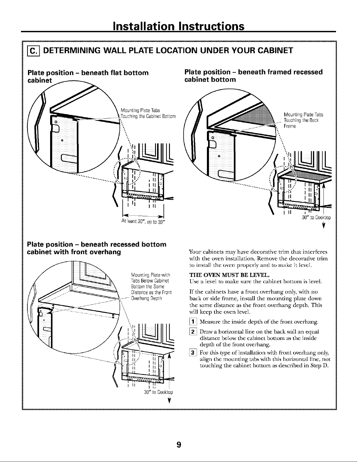
[] DETERMINING WALL PLATE LOCATION UNDER YOUR CABINET
Plate position - beneath flat bottom
cabinet
Maunth_gPI_teTabs
Plate position - beneath framed recessed
cabinet bottom
Moum:ingPlateTabs
Teuchi_gthe Back
Frame
Plate position - beneath recessed bottom
cabinet with front overhang
II
30" to Cooktap
S%ur cabinets may have decorative trim that intertcres
with d_e oven inst_dlation. Remove the decorative n'im
to install the oven properI_ and to make it level.
THE OVEN MUST BE LEVEL.
Use a l_'eI to make sure the cabinet bottom is level.
If' the cabinets have a lyon t overhang only, Mth no
back or side &ame, install the moundng plate down
the same distance as the &ont ore€hang depth. This
will keep the oven level.
[] Measure the inside depth of the fl'ont overhang.
[] Draw a horizontal line on Ihe t_ck _vall
distal_ce below the c_binet bottom ;_ the inside
depth of the fi'ont ove_:hal_g.
[] For I}fis t}_e of inst_dlation with front
align Ihe moundng u4bs with Ih:is horizonud line, not
touching the cabinet tx_ttom as descrit_d in Step D.
all
eqt_]
overhal]g onl}_
9
Page 10
Installation Instructions
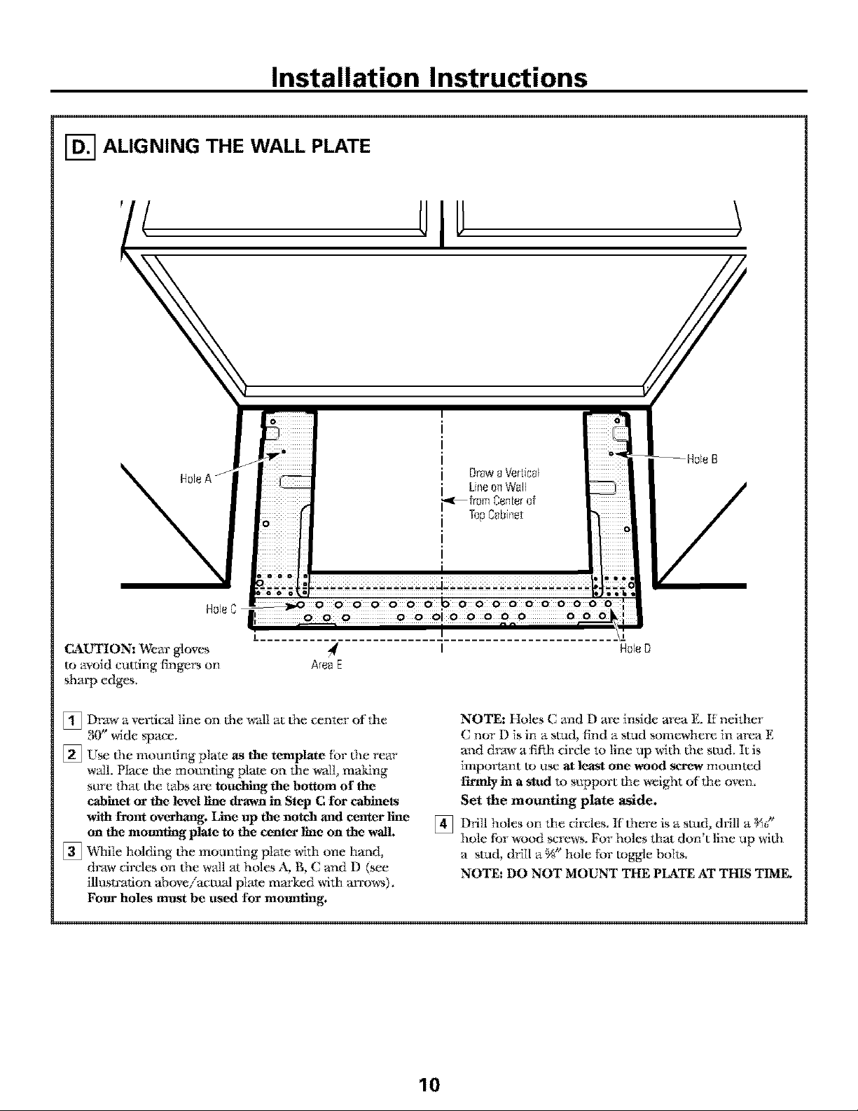
[] ALIGNING THE WALL PLATE
HoleC _ 0 0 0 0 b 0000000000
CAUTION: Wear gloves
to avoid cutdng fingers on
sharp edges,
Draw a ve*_ictd line on the wall at (he center of the
[]
3(Y' wide space.
[] Use (he mounting plate as the template [br (he rear
wtdl. Place the mortaring plato on the wall, making
sttre lhat the tabs are touching the bottom o1' the
cabinet or the level llne dl_awn in Step C [or cabinets
with [font overhang. Line up the notch and center line
on the monnting plate to the center line on the wall.
[] Dc]ai[e holding (he mounting plate with one hand,
draw circles on (he wall tat holes A, B, C and D (see
illustration aboveiactuM plate marked with an:ows).
Fore* holes mttst be used for mounting,
0 0 0 O 0 OI 0000O 000
Area E
I
NOTE: Holes C and D are inside area E. ff neilher
C nor D is in a stud, find a stud som_here in area E
and draw a fifth circle to Iine up M(I_ (he stud. It is
imporlant to tt_ at least one wood screw mortared
firmly in a stud to support the weight of the oven.
Set the mounting plate aside.
Drill holes on 1he circles. K there is a stud, drill a _a"
[]
HoleD
hole tbr wood screws. For holes that don't line up wifl_
a stud, drill a %" hale tbr toggle bolts.
NOTE: DO NOT MOUNT THE PLATE AT THIS TIME.
10
Page 11
Installation Instructions
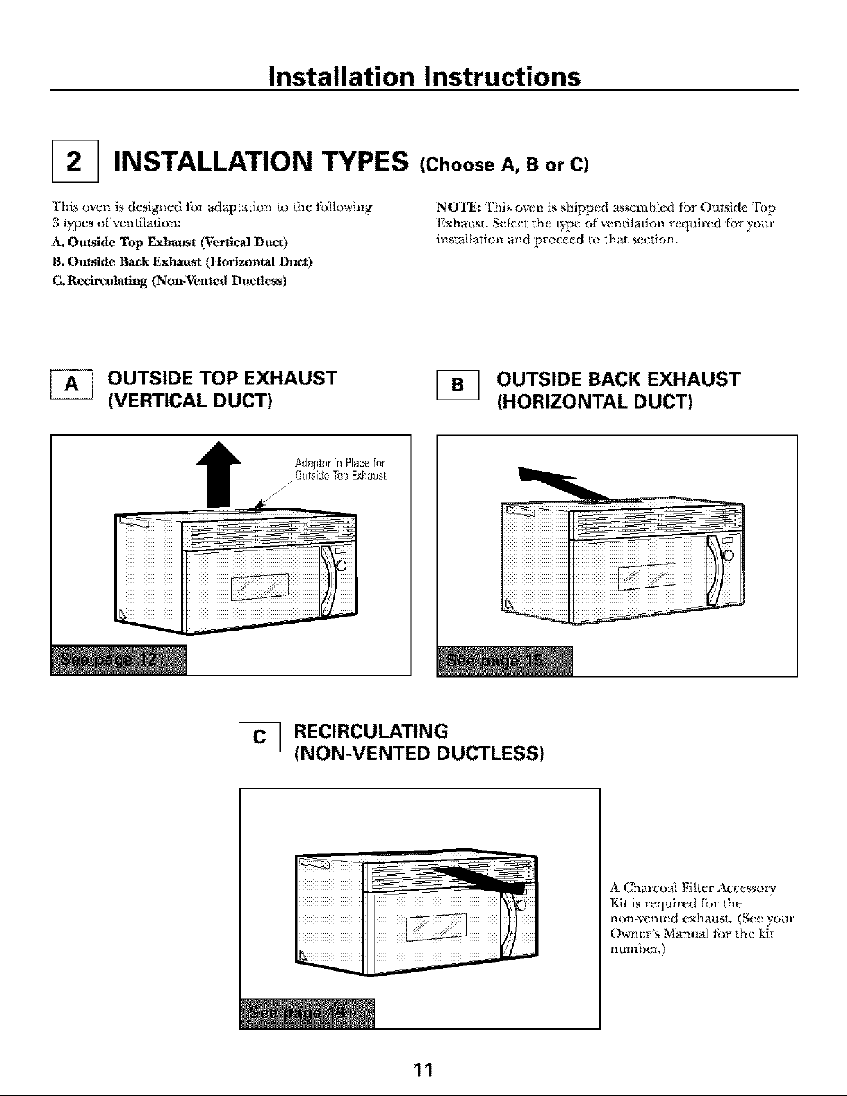
INSTALLATION TYPES (Choose A, B or C}
This oven is designed fbr adaptation to the fbllowing
3 t}pes of ventilation:
A_Outside Top ExhatJst (Vertical Duct)
B÷Outside Back Exhaust (Horizontal Duct)
C. Recirculatmg (Non-Vented Ductless)
OUTSIDE TOP EXHAUST
(VERTICAL DUCT}
NOTE: This oven is shipped assembled fbr Outside Top
Exhaust, Select 1he t)pe ofventiIadon required fbr your
installation and proceed to that section,
OUTSIDE BACK EXHAUST
(HORIZONTAL DUCT}
RECIRCULATING
(NON-VENTED DUCTLESS}
11
A Charco;d Filter i_cessory
Kit is required tor the
non-vented exhaust, (See your
(_er's ManuN fbr the kit
numbe_:)
Page 12
Installation Instructions
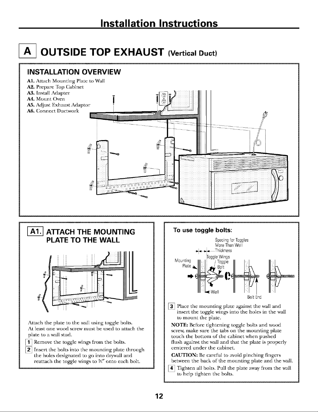
OUTSIDE TOP EXHAUST (Vertical Duct)
INSTALLATION OVERVIEW
AI÷ Attach Mounting Plate m Wal]
A2. Prepare "Fop Cabinet
A3. Install sL_apter
A4. Moant Oven
A_. Adjust Exhat_st Adaptor
A6. Connect Ductwork
m
ATTACH THE MOUNTING
PLATE TO THE WALL
Attach the plate to the wtdl rising toggle bolts,
At least one wood screw most be osed to attach the
p]ate to a wall stud,
[] Remove the toggle win_ ti'om the bolts.
[] Insert the bolts into the mounting plate through
the holes designated to go into dD_dl and
reattach tile toggle wings to %_"onto e_ch bolt.
To use toggle bolts:
Sp_cin__orIo,agles
MoreThanWoll
_l,,,_Thickn ess
Iro_leWin_s
Mou_tin_ IIl, lJ /To!NI'_ II II
BoltEnd
[] Place the mounting plate against the wall m_d
insert the toggle wings into the holes in the wal]
to mount the plate.
NOTE: Befbre tightening toggle bolts and wood
screw, make sure the tabs on the mounting plato
touch the bottom of the cabinet when pushed
flush against (he wMl and (hat the plato is properly
centered trader the cabinet,
CALrTION: Be carefuI to avoid pinching fingers
between the back of' the moondng plate and the wM1.
_ Tighten all bolts. Pull the p]ate away fi'om the wM1
to help tighten the bolts,
12
Page 13

Installation Instructions
[-_ USE TOP CABINET TEMPLATE
FOR PREPARATION OF TOP
CABINET
You need to drill holes fbr the top support screws,
a hole large enough fbr 1he power cord to fit through,
and a cutout large enough fbr the exhaust adaptor:,
• Read the instructions on the TOP CABINET
TEMPIJVFF.
• Tape it underneath the top c_4binet.
• Drill the holes, fblloMng the instructions on the
TOP CABINET TEMPIATE.
CAUTION: Wear s_4"et}goggles When dfilEng holes
in the cabinet bottom.
[-_ ASSEMBLE AND
INSTALL ADAPTOR
MOUNT THE OVEN
FOR E_IER INSTALIz_-TION AND PERSONAL
SAFE'I'_ V_ RECOMMEND THAT TWO PEOPLE
INSTALL THIS OVEN.
IMPORTANT: Do not grip or use handle
during installation.
NOTE: If yore" cabinet is metal, use the n) ion
grommet around the power cord hole 1o prevent
cutting of Ihe cord,
NOTE: We recommend using filler blocks if the
cabinet front hangs below the cabinet bottom shelf
IMPORTANT: If filler blocks are not
used, case damage may occur from over
tightening scwews.
NOTE: When mounting the
oven, thread power cord
through hole in bottom
of top c_,/binet, Keep it tight
throughout Steps 1-_L
Do not pinch cord or lift
oven by p_flling cord,
_Liff tilt itoven,
forward, and hook
slo_ at back bottom
edge onto two lower
tabs of mounting
plam.
\
[_ Place the oven in its upright position, with the top
of the unit tacing up.
[] Insert 0_e tabs on each side of 0_e damper into the
holes at the inside *:ear:of the adaptor.
_ Attach the exhaust adaptor to the blower plate with
the two bronze metal screws provided.
Make salre that the damper pivots easily before
mounting oven.
_'_u wit1 need to make adjusmaents to asstu'e proper
_dignmen t with your house exhaust duct after the
oven is installed.
]Rotate front of
up against cabinet
bottom.
_ Insert a self-aligning screw Ihrough top center
cabinet hole, "I_mporarily secure the oven by
turning the screw at least two full mrus after the
thrmuls have engaged. {It MII be completely
tightened iatm;) Be sure to keep power cord tight.
Be careful not to pinch the cord, especially when
mounting flush to bottom of cabinet.
oven
13
Page 14
Installation Instructions
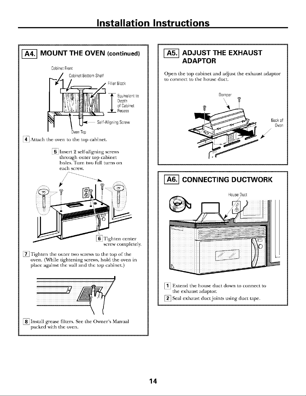
MOUNT THE OVEN (continued)
@bineJ:Front
:'Z C_;bineJ:BottomShelf
Iia_A FillerBlock
. T' i.alo,,"o
/K'F//BI!II /IIJI/0%,,0,
--Ove_l Top
I:_"-t'_:htI,eoventothetopca_>h_et,
r l
j 5 jInsert 2 sel_:Migning screws
through outer top cabinet
holes, Turn two rid] turns on
each screw;
[-_ ADJUST THE EXHAUST
ADAPTOR
()pen the topcM)inet and a_itiust the exhaust adaptor
to connect to I]_e house duct,
D_mper
Back_f
Ove_
#
[-_ CONNECTING DUCTWORK
House DUC[
[]Tighten cenmr
screw completely,
[] Tighmn the outm: two screws to the top of the
oven, (While tightening screws, hold the oven in
place against the wall and the top cabinet,)
[] Insudl grease tilmrs, See the Owner's Manual
packed with the oven,
_ Exmnd the house duct down to connect to
the exhaust adaptor;
[] Stud exhaust duct joints using duct tape,
14
Page 15
Installation Instructions
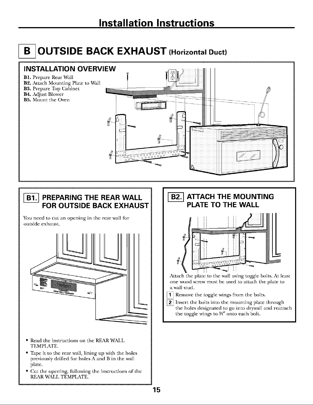
OUTSIDE BACK EXHAUST (Horizontal Duct)
INSTALLATION OVERVIEW
B1, Prepare Rear Wall
B2, Attach Mounting Hate m Wail
B3, Prepare "Fop Cabinet
B4, Adjust Blower
B5, Motmt the Oven
PREPARING THE REAR WALL
FOR OUTSIDE BACK EXHAUST
You need to cttt an opening in the rear wall [br
outside exhaust.
• Read the instructions on the REAR WALL
TEMPI_TE,
• Tape it m the rear" _all, lining ap wi(h the holes
previously drilled tot holesA and B in the wall
plate,
• Cut the opening, [bllowing the instrnctions of the
REAR W_\LL TEMPI_\TE,
ATTACH THE MOUNTING
PLATE TO THE WALL
Attach the plate m the wall using toggle bolts, At least
one wood screw mnst be used to attach (he plate to
a _all stud,
[] Remove the toggle wings from the bolts.
[] Insert the bolts into the mounting plate through
the holes designated m go into dlwwalI and reattaeh
the toggle win_ to g*'_ onto each bolt,
15
Page 16

Installation Instructions
To use toggle bolts:
Spacingfer Tu!NlesMore
_ ThanWaft Thickness
ITe_lsw,n_s
M_um:ing i 7 I"
• ', 0!Ne ,
'a e41.'l,.Zgo,II I:1-,
" I't
II U I
golt End
[] Place dm mounting plato _ainst the wall and
insert the toggle wings into the holes in the wall
to mount the plate,
NOTE: getbre tightening toggle bolts and wood
screw; make sure the tabs on the mounting pla_
touch (he bottom of"the cabinet when pushed flush
against the wall and that the plate is properly
centered trader the cabinet,
CAUTION: Be caref'uI to avoid pinching fingers
between the back of' the moun ling plate and dm wall,
[] Tighten all bolts, Pull the plate awW from the wall
to help tighten the bolts,
F-_ ADAPTING BLOWER FOR
OUTSIDE BACK EXHAUST
[] Remove the three scr_wcs that hold the blower
plate to (he oven. Slide blower plate from trader
its retaining flange. Remove and save (he screw
that holds Mower motor to oven.
glower Rate
_ (]areftfily tim blower unit. The wirespuI1
will extend Jar enough to allow you to adjust
the blower unit,
out
EndB
USE TOP CABINET TEMPLATE
FOR PREPARATION OF TOP
CABINET
You need to drill holes fbr the top support screws and
a hole lm:ge enough fbr the power cord to fit through,
%
%
• Read tim instructions on the TOP CABINET
"rI?]MPIz\TE.
• Tape it underneath (he mp cabinet.
• Drill the hoIes, fbllowing the instructions on the
TOP CABINET "rI?;MPI J\TE.
CAUTION: WEar safe g goggles when drilling holes
in the cabinet bottom,
_ Rotate blower unit counterclockwise 180%
Be[oreRototion After Rototion
Oven
[] (_ntly remove the wires fi:om the
Reroute the wires through grooves on other side
of"the blower unit,
Be[oreRerouting Aher Reroudng
grooves,
gockof
Oven
16
Page 17

Installation Instructions
[]Roll the blower trait 90 ° so that ffan blade
openings are f_acing out the back of' the oven,
8ockef 8ockef
[] Locam the two "knockout" plains, on the rear
oven pm_el, near the top of the oven.
Using tin snips, carefully cut the web area f}'om
the two holes side-by-side (I;hat sectlre 1he
knockouts to the oven). Ct_t all fbtlr webs on bolh
rear knockouts; Lhis will M]ow the yen tilation fian
_dr flow to exhat_st ot_t the rear of' Lhe oven.
CAUTION: Be sure to trim the sharp edges from
the openings af*er removing the knockout plates.
Oven Rear Panel
Snipall 4webs
_neachk_ockeul:
g_el o_dremove
t]_emetal knock_u[s
f_rre_ra_rflo_,',,_
[] Replace the blower plate in the same position
as befi)re with the screws.
BlowerPlo[eScrews
J
_ 8lower Plate
[] Insert the tabs on each side of' the dt_per into
the holes at the inside rear of (he adapto_;
Adep[or
_ Attach the exhat_st adaptor to Lhe rear of the
oven b> sliding it into the gtlides at the top
cenmr of' the back of the oven.
E×houstAdeptor
_.._ Damper
(hhlgesideup)
[] Place the blower unit back into the opening.
CAUTION: Do not pull or stretch the blower
unit wiring. Make sure the wires are not pinched.
NOTE: The blower unit exhaust openings should
match exhaust openings on rear of oven.
Slideexhaust
adaptorinto
guides0n
ovenfear
dF .
"V'Scre''s
Tabs Guides
Pt_sh in sec_rely until it is in the lower locking
tabs. Take care to t_ss_re the damper hinge is
installed so that it is at fhe mp and Lhat the
damper swings ffreeI};
_ Secure the exhaust adaptor m the oven wiLh the
two bronze meted screws provided.
17
Page 18

Installation Instructions
MOUNT THE OVEN
FOR FgkSIER INSTIM,I_\TION AND PERSONAL
St_'_TIS_ V_ RECOMMEND THAT TWO PEOPLE
INSTALL THIS OVEN.
IMPORTANT: Do not grip or use handle
during installation.
NOTE: Ifyonr cabinet is metal, use the nylon
grommet arotmd the power cord hole m prevent
ct*tdng of the cord.
NOTE: D¢_ recommend using t_ller Mocks if the
cabinet ti'ont han_ below the cabinet bottom shelf.
IMPORTANT: If filler blocks are not
used, case damage may occur from over
tightening screws.
0ve_Top
[_Attach the oven to the top cabinet.
[] Insert 2 self:_digning screws
through ot_ter top cabinet
holes, Tm'n two titll turns on
each screw;
iiiiiiiii!
NOTE: When moundng
film oven, thread power
cord through imle in
bottom of top c_4binet.
_ep it tight throughot_t
Steps I-3. Do not pinch
cord or lit_ oven by
p_flling cord.
[_ Lit:t oven, dlt it
fbrwm'd, m_d hook
slots at back bottom
edge onto two lower
tabs of' mounting plate.
[_ Rotate tYont of oven up
against ct-fbinet bottom.
[] Insert a self:tdigning screw through top center
c_/binet hole. Temporarily secure the oven b)
turning _he screw at least two fMI turns afl.er the
threads have engaged. (It will be completely
tightened late*:.) Be sure to keep power cord tight.
Be carefxd not to pinch the cord, especially when
mounting flush to bottom of cabinet.
[]Tighten cenmr
screw completely.
[] Tighmn the oater two screws to the top of the
oven. (While tightening screws, hold the oven
in place against the wall and the top cabinet.)
[] Insudl grease filmrs. See the Owner's Manual
packed with the oven.
18
Page 19

Installation Instructions
RECIRCULATING {Non-Vented Ductless)
INSTALLATION OVERVIEW
C1. At:ach Mounting Plate to Wall
C2. Prepare Top Cabinet
C3. Adjust Blower
CA. Mount the Oven
C5. Insudl Charcoal Filter
[_ ATTACH THE MOUNTING
PLATE TO THE WALL
Attach the plate m the wtdl using toggle bolts. At
least one wood screw must be used to attach the
plate to a wall stud.
[]Remove the toggle win_ Dora the bolts.
[nsert the bolts into the nlountin ' la_ throu 'h
[] gP g
the holes designated to go into d*)wldl and
reattach the toggle wings m _A_'onto each bolt.
To use toggle bolts:
SpacflLaforTuggles
MoreThanW_fll
4_Thickness
%ggleWin£s
Mounting i -/Toggl'e
[] Place 1he mounting plate against the wall m_d
insert the toggle wings into (he holes in the wall
to mount the plate.
NOTE: Betbre tightening toggle bolls and wood
screw, make sure 1he tabs on the mounting plato
much the bottom of the cabinet when pushed flush
agtdnst the wall and that the plate is properly
centered under the cabinet.
CAL_TION: Be carefuI to avoid pinching fingers
between the back of' the mortaring plate and the wtdL
[] Tighten all bolts. Pull the plate away ti:om (he w_dl
to help tighten the boils.
USE TOP CABINET TEMPLATE
FOR PREPARATION OF TOP
CABINET
_,_u need to drill holes [br the top support screws and
a hole large enough fbr the power cord to fit (hrough.
_=========_
• Read the instructions on the TOP CABINET
TEMPLATE.
• Tape it underneath the mp cabinet.
• Drill ttm holes, tbllo_ng the instructions on the
TOP CABINET "rEMPIJ\TE.
m t,qr_Wall , P i
BollEnd
CAIYrION: Wear safer) goggles when drilling holes
in the c_-ff_inetbottom.
19
Page 20

Installation Instructions
ADAPTING BLOWER
FOR RECIRCULATION
NOTE: The exhaust t_laptor with dmnper is not
needed tor recircularSng models, You may want to
save (hem _br possible t'umre use,
[]Remove and save screws that hold blower plum to
(}le oven,
_ _ 8lowerPlateScrews
II
I i .....
2 j Shde (he blower plum from under its relammg
flange and I ti it off; Remove and save screw fihat
holds the blower motor to oven,
_1 Carefullv ptfll out the blower unit. The wires
' will exm]_d tar enough m allow you to a([iust the
blower unit.
_i Roll the blower unit 90 ° so that tan bl;_le openin_
Jare fiming toward the &ont of the oven.
_j glowerRate
I : _ Screw
R011
NOTE: Make sure wires remain toured in the
grooves of the motor fi'ame,
2O
Page 21

Installation Instructions
ADAPTING BLOWER FOR
RECIRCULATION (continued)
[] Place the blower trait back into tim opening.
CAUTION: Do not pull or stretch the blower unit
wiring. Make sure tile wirc_ are not pinched,
[] Secure blower trait to oven with the screw
removed in Step 2, Insert the screw in bottom
right screw hole on the back of the oven.
[] Replace b]ower p]ate wi(h the screws removed in
Step I.
_'_ BlowerPIsteScrews
NOTE: When mounting
the oven, thread power
cord throt*gh hole in
boltom of mp cabinet,
Keep it tight throt_ghot_t
Steps l-& Do not pinch
cord or lift oven b_
pulling cord. _ I
[_ Rotate fl:ont of oven
up against cabinet
bottom,
_Insert a self-aligning screw throt_gh top center
cabinet hoIe, Temporarily secm'e the oven by
turning the screw at least two f_ tarns after the
threads have engaged÷ (It will be compIetely
tightened late*;) Be sure to keep power cord fight.
Be careful not to pinch the cord, especially when
mounting lllJsh to bottom or cabinet.
[] Lig oven, tilt it
forward, and hook
slots at bt_k bottom
edge onto two lower
tabs of mounting plate,
\
\
MOUNT THE OVEN
FOR E_[ER INSTALIzkTION AND PERSONAL
SAFE°In*, WE RECOMMEND THAT TWO PEOPLE
INSTALL THIS OVEN.
IMPORTANT: Do not grip or use handle
during installation.
NOTE: If your cabinet is meLtd, use the nylon
grommet around the power cord hole _.oprevent
ctttting of the cord.
NOTE: We recommend t_sing fleer blocks if 0_e
cabinet front hangs beIow the cabinet bottom she]£
IMPORTANT: If filler blocks are not used,
case damage may occur from over tightening
screws,
C_;binel:Front
?A C_;binel:Be[IotaShelf
r---¢1/ . FillerBk_ck
r,-,v
I[,!,.,'_/]]--1Tao,_,e..: l:oDep.:,,
/ /0rc_,_*.0.:Rece.
,. !
Ove_Top
_Attach the oven to the top cabineL
21
Page 22

Installation Instructions
MOUNT THE OVEN
(continued)
[] Insert 2 self-aligning screws
throngh outer" top cabinet
holes. Turn two full tm'ns on
each screw,
[] Tighmn center
screw complemly.
[] Tighten (he outer two screws to the top of the
oven. (While dghmning screws, hold the oven
in place agMnst (he wNl and (he top cabinet.)
[-_ INSTALLING THE
CHARCOAL FILTER
[] Remove 2 screws on top of grille using a
Phillips screwdriver;
[] Open the door;
[] Remove the grille.
[_ Insert the filter into the
maneuvering it behind the plastic grille tmfil it its
squarely into place. It will rest at an angle behind
the plastic grille on two side support tabs and in
fi'ont of the right rear tab. When properly
installed, the wire mesh of the filter should be
vMbIe fi:om the fi'ont.
shown_oven as
[] Install grease filters. See the Owner's Man ual
packed with the oven.
[] Replace the grille and the 2 screws,
[6_ Close the door,
h_sertmesh-siOedow_
22
Page 23

Installation Instructions
BEFORE YOU
M_fke s{_re the oven has been inst;dled
;_:cord_ng to b_structions,
USE YOUR OVEN
Read the Owner's Manual,
KEEP [NSTALI_\TI()N INSTRE CTI()NS
FOR THE LOCAI, INSPECTOR S USE,
ial fl'om the oven,
[] Replace house gtse or turn bretfker back on,
_] Plug power cord into a dedicated 15 to 20 amp
electrical outlet,
f
Insure _r0[_er
_rt_u_dexis[s/ @_ef_re use
23
Page 24

24
Page 25

Instrucciones
ornopara,colocar
de instalacibn
enczma la estufa
JVM1490,SCA1000y SCA1001
j iPreguntas? Uame 800-GE-CARES(800-432-2737)o ,_ite,_,_e_trap':_i,-,_enJ',_rede,,: j
www.GEAppliances.com
ANTES DE EMPEZAR
Lea estas instrucciones completa y cuidadosameme.
IMPORTANTE
• _ (_Ll_tlTde esLas
instmcciones para el t_so dei inspector local,
IMPORTANTE - Comp,._on
todos ios c6digos _ ordenanzas gubernamentales,
• Nota para el instalador _ Asegfirese de dcjar
e_ta_ J_[rtl_:cione_ con e] co,_lmJdor,
• Nota para el consumidor _ Gtiarde estas
instr,IccJones para fimira ret_:rencia.
• Nivel de destrezas - La instah_cidn de este apm'ato
veqtfiere dc dcstrezas b;_sicas de mecSnica y electficidad.
• La insudaci6n apropiada es responsabilidad
del instaladm;
• La tal]a del producto debido a una instalaci6n
inapropiada no estfi cubierta pot In g_avantfa.
25
LEA CUlDADOSAMENTE.
GUARDE ESTAS INSTRUCCIONES.
Page 26

Instrucciones de instalacibn
B
CONTENIDO
Informacibn general
lnstrucciones de seguridad importantes ................ 27
Requisitos el6ctricos .............................................. 27
Campana de escape .......................................... 28, 29
Dafios - Envio / lnstalaci6n .................................. 30
Partes inchfidas ...................................................... 30
Herramientas que necesitarfi .................................. 31
Espacio de montaje ................................................ 31
Guia de instalaci6n paso por paso
C6mo colocar el plato de montaje .................... 32-34
C6mo remover d plato de montaje ............ 32
C6mo encontrar madera s6lida
en ]a pared .................................................. 32
C6mo determinar [a [ocalizaci6n
de las plac_ de la pared ............................ 33
] Recircnlaci6n ........................................ 45-46
C6mo adherh eI plato de
monU_e a ]a pared .............................. 43
C6mo prepm_ar el gabinete snperior..43
C6mo adaptar el cMefacmr
pm'a ]a recircOaci6n ...................... 44, 45
C6mo montar el horno .................. 45_ 46
C6mo insudar el filtro de carbonilla..4fi
Antes de comenzar a usar su homo ...................... 47
C6mo alinear [a plata de la pared .............. 34
Tipos de instalaci6n .......................................... 35-46
[]Escape snperior ........................
C6mo adherir ia placa de
montaje a la pared .............................. 36
Preparacidn de] gabinete superior ...... 37
C6mo inspeccionar si Ia operacidn
de] regulador de Iiro es apropiada ...... 37
C6mo montar d homo .................. 37, 38
C6mo ajustar el adaptador de escape .38
C6mo conectar ]a red de conductos.÷÷38
_ Escape posterior externo ...................... 39-42
(176mo preparar ]a pared poslcrior
para el escape posterior exmfior ........ 39
C6mo adherir el plato de
montaje a la pared ........................ 39_ 40
(i_6tno preparar el gabinete superior..A0
ex_rior 36-38
C6mo adaptar el cMePacmr para
el escape exterior posterior ........... A0_ 41
C6mo montar d homo ........................ 42
26
Page 27

Instrucciones de instalacibn
INSTRUCCIONES DE SEGURIDAD IMPORTANTES
Estc producto requiere un u>maco_¢ientc ddctrico
de u'es patas conectado a tierra. E1 _nsttdador debe
]le_r a ct(bo tma _nspe_ cidn de confinu_dad a fiesta
en la c;_a eldctvica antes de comenzar la insl_flad6n
para asegurar qt_e la caja tom_orrienm esl_i conectada
a derra de manera apropiada, N no lo esul, o si el
tomacorTientc no cumple con log requisitos
eldctricos _ndic_los (bajo ]a seccidn REQL'ISYFOS
ELECTRICOS), se deber_i recurcir a tm tdcnico
cMificado para corregir cuNqu_er defidencia,
PREC&UCION:
Para segLwidad personal
remuc_a el fusible de
la casa o abra el intemq)tor
de circxfito ant_ de
comenzar la imtalad6n
para c_itar d_cargas
el_ctricas se_ras o l'al_.
PRECAUCION: En pos de la segaridad personal,
la superficle de montaje debe ser capaz de soportar
la cargm dcl gabinetc, adem_ de1 peso adicional
(de 63 a 85 libras) de _te producto, mils las cargas
adicionales del homo de lmsta 50 Flbras o un p_ total
entre 113 y 135 libras,
PRECAUCION: En pos de la segnridad personal,
este producto no puede set instMado en sistemas de
gabinet¢_ tales como los llamados "islas" o "l_nim'_-flas",
Este debe set montado tanto a un gabinete superior
como a tma pared.
NOTA: Para tma instalaciOn n_s fMl y en pos de la
segt_idad personal, se reconfienda que (los personas
instalen este produc*o÷
IMPORTANTE: POR FAVOR, LEA
CUIDADOSAMENTE. EN POS DE LA SEGURIDAD
PERSONAL, ESTE APARATO DEBE SER
CONECTADO A TIERRA APROPIADAMENTE PARA
EVITAR DESC&RGAS SEVERAS 0 FATALES.
E1 cable el_c_co de este
aparato esN eqnipado con
tm cnclmfc de tres paras
(c_n conexidn a ti_),
lo carol reqlfiere que el
mismo enc_je con un
tomacorriente para tres
paros (con conexiOn a tierra
de pared para min'unizar
la posibilidad de
descm'gms clfic_s.
Deberft lmcer que un t_cnico calificado inspeccione el
tomacorriente de pared y el circttito para _gtma'se de
que el tomacorriente _t6 conectado a tierra de manera
apropiada.
Domle usted encuemre tm tomacomente est_mlm- de
dos paras, ¢_ m W hnportante quc lmga que d mismo se
cambie pcsr tmo de trc_ paras apropiadamcnle conec_ado
a fierl_ imtalado pot" tm elec_ricista catificado.
RAJO NINGUNA CIRCUNSTANCIA NO CORTE,
DEFORME, O REMUE$_ NINGUNA DE LAS PATAS
DElL C&BLE EI_CTRICO÷ NO IX) USE CON UNA
EXTENSION ELI_CTRICA.
REQUISITOS
ELECTRICOS
La dasiflcaci6n de} producto es de 120 ratiosCA
(AC), 60 herlz, 15 ampefios, y 1,70 kilovafios, Esm
producm debe estar conectado a un circuim de
stmfin_stro de} vo}taie y ti'ectlenda aprop_ados, E1
tamafio de} _/lmnbre debe contbrmarse a }os requ_shos
del NafionM Electric Code o M cdd_go loom en egccto
para este fnd_ce de kilowafios, El cable eldctrico de
Mimentacidn y el _nwrruptor deberan lle_r._e a m_
tomacorfiente finico conecmdo a fierra de 15 a
20 amperios, La ct&ia del tomt_:ovcienm deberfi estar
locMizada en el gabinem encima del homo, La
c_a de} tomacovcienm debe ser instalada por tm
elecu'_cista cM_ficado y debe confbr_arse _d NadonM
Electrical Code o aI cdd_go ]oc_d en egecto,
27
Page 28

Instrucciones de instalacibn
CAMPANA DE ESCAPE
NOTA: Lea las siguientes dos p_inas solamc_nte si planea venfilar el escape hacia el exterior.
Si por el contrario planea rccircular el sire de vuelta hacia el sal6n_ con_fie en la pfigina 30.
ESCAPE SUPERIOR EXTERNO (EJEMPLO SOLAMENTE)
La _iguientc u4bla describe _m ejemplo de una po_ible
instt_ilacidn de red de conductos.
LONGITUD NUMERO LONGITUD
PARTES DEL CONDUCTO EQUlVALENTE x USADO = EQUlVALENTE
_ Tape del techo 24 pies x (1} = 24 pies
Cenducte recto de 12 pies 12 pies x (1} = 12 pies
La lengitud de las partes de los cenductes equivalentes est_ basedean pruebas reales y reflejan los
requisites pare bgrar unabuena ventilacidn con cualquier campana de escapeLongitud total 41
IMPORTANTE• SI se t_sa un adapmdor de trm_sici(m de recffmguto a redondo, ias es_ ulnas del tbrldo
deI ye_'ulador de tiros deberfin cortm:se para qua encajen, tlsando ]as tijeras de corm, para permidr e]
mo_arnmnto libra del regu]ador de tiros.
ESCAPE POSTERIOR EXTERNO (EJEMPLO SOLAMENTE)
La sigtfiemc tabla desclibe an _emplo de nna posiMe
instaltcci6n de red de conducms.
LONGITUD NOMERO LONGITUD
PARTES DEL CONDUCTO EQUlVALENTE x USADO = EQUlVALENTE
Conducto recto de 3 pies 3 pies x tl} 3 pies
trectangular de 3W" × 10"}
pies
Codede gO* 10 pies x t2} 20 pies
ka bngitud de los partes de los conductos equivalentes est_ basada en pruebas reales y reflejen los
requisites pare Iograr una buena ventilecidn con cualquier carnpana de escapeLongitud
NOTA: Pant el e_ _tpe pc_reriol; _e debe tener cuidado _d al_near el escape entre los e_pac_ de los pc_ms de vi_t de 1_1pared
o la pared deberfa _er preparada en el momenta de _u con_rruccidn deiando _ufidentt _,espacio entre 1o_ postt_,_ de riga de la
pared para acomodar el escape.
total 63
pies
28
Page 29

Instrucciones de instalacibn
NOT.&: Si osled neceska instaIar conduc_.os, tonga
pendlente quc la longitud tomI del c*)nductu redangular
de 3¼"x I0" o e1 condt*c:to redondo de W de di_metro
nO debe sotn*cpasar 140 pies equivalcntes,
La vendlaci6n extema requiere un CON_UCTO DE
CAMI)ANA DE ES(_M)E. Lea Io siguJente cuidadosamenm.
NOTA: Es importm_m qtle Ia x_cnd]aci6n _a insud_la
usa_do ]art:_Vam_s direcm y c_n la menor canf*&adde codus
pmible. Esto asegum la _cntilaci6n del e_'ape ywuda a
prevenir bloqtmos. Tambi_n, cexvi6rese de qam d _gtlladoi"
de tim pende libremente ynada bloquea los conductos.
Conexiones de escape:
La campana de escape ha sido di_fia&a pz_a encajar con
un c*mducto rectangtflar de _¼" x i0" esl_ndar.
Si un c*mducm redondo es necesm4-o, s_ debt usa*"un
adaptador de wansici6n de rectangaJar a redondo.
No use on conducto menor de 6" de di_imetro.
LONGITUD
PARTES DE CONDUCTO
Adaptadorde transiciOnde
rect_nguloa redondo*
EQUIVALENTE x
5 pies x
Longitud mfixima del conducto:
Pare logrm" un movimiento satisfactorio de1 aire, ia
longimd total del conducto rectangtflar de B_A_'x i0"
o eI conducm redondo de W de di_metro no dcbe
sobrepasar 140 pies equivalentes.
Los codos, transiciones, paredes y tapas
de techo, etc., presentan resistencia adicional al
flt_jo de aire y son equivalentes a una secci6n de
conducm recto el ctudes m_s largo que su tamafio tTdco
real Cuando c_dcule Ia Iongimd toud del conducm,
agregue 1as Iongitudes eqtfivalentes de todas 1as
transiciones y adapta_:lores, mas la Iongitud de mdas
1_ secciones de conducto rectus. La table mg_sadelante
muestra c6mo puede calcular la longimd aproximada
de la red de conducms usando pies aproximados de
longitudes equivdlenms de algunos conductos tfpicos.
NUMERO
USADO
( )
= EQUIVALENTE
LONGITUD
pies
(:
J
Tapade pared
Codode90'>
Codode45'>
Codode90'>
Codode45'>
Tapade techo
m
Conductorectode6_"redondo
o rectangularde 3W' x 10"
40 pies x
10 pies x
5 pies x
25 pies
5 pies
24 pies
1 pies
x ( )
x ( )
x ( )
x ( )
( )
( )
( )
pies
pies
pies
pies
pies
pies
pies
Total red de conductos =
recv;_Ntdo a rcdondo, 1ascsql_ina_ del tb_Ido dd rf%ulador cn pn_cl_s reales y r_tlqjan los requisltos pare Iog_ar _ma buena
d_,! eros tt(_i _r col-_y, bl_ p_ t_[l__ (_rlc_i_ I/_ldo |a,s _z! (ilal_erl cori (:_q/l[_r ca_ipa_ia dc _,_cap_%
* IMYOR'I}kR't*: 81 _c ttsu m adapmdor d_: wansil:iezi d< La longiVad de la.__t:s de condm:ros cquiwtk m*'s ¢-st;i{_l_a
_.ic_ de co_t_, p_ pe_ni_r d mo_micn_ librc dd
rcg_d_or de drop,
pies
29
Page 30

Instrucciones de instalacibn
DAI_iOS - ENV|O /
INSTALACION
" Si la _midad se dafia durante el cnvio_ devuciva la
mfidt_l td tdmacdn donde la adqtfiri6 para s(l
repavaci6n o rcemplaxo.
" Si el cliente *Jaffa la uffldad, ]a rcparaddn o c]
reemplaxo es responsab_lidad del c]Jente.
" Si el instalador dafia la uffldad (si no es el cl_enm),
la repavaci6n o reemplaxo se debe hater par
media de un arreglo entre el cl_enm y el instMador;
PARTES INCLUIDAS
PAQUETE DE ELEMENTOS
PARTE CANTIDAD
TorNI!os de madere 2
(_'_"x 2'1
/ a rornil!os besculantas 4
_ (ytuercas de mariposa)
/
(_'t"x Y')
rornil!os de m_quina 3
autoalineables
(_'_"-28x 3W')
PARTES INCLUIDAS
PARTES ADICIONALES
PART
Plantillapara
etgabineta
supenor
Plantillapare
M_
®
le pared
_osterior
Instruccienes
deinstaleeidn
Filtrosde
grese
empecades
par separado
Arandele eislante de
hilton(pare gabinetas
rnet_licos)
Adaptador del escape 1
Regulador de tiro 1
rornil!os pare metal 1 negro
(7," x _'Z') 2 de bronce
Abrezadere del cable 1
el_ctrico (pl_stice}
Usmd encontrara los clementos de insudacidn en
un paquemjtmm con la tmi&_l. Inspeccionc para
cerciovarse de quc fienc mdas las partes.
NOTA: Se incluyen Mgtmas parma adicionMes.
2
30
Page 31

Instrucciones de instalacibn
HERRAMIENTAS QUE NECESITARA
Destornflladoresdeestrella
#Iy#2
Tijeras para cortar laJ:6_
de Lifo,si es i_ecesorio}
plom:illa,siesilel:esario}
L_lpiz
T_flodroel_cLrico co_ brocos de
Guantes Detecterde
Sierra(desableaguieroo de posiesderig 1 e ulllrlartfllo{opcionol)
oiodecerrador;}
ecto y Ci_[a m_Lrica
Nivel
Escuadrode
carpintero
(epcio_fl)
Bequesderelle_me
pedazosdemodero,si so_
necesoriospararellenorel
enIofl_stalasidnde
£abi_etes_pey_des)
Cintadeco_ductoso
cim:oodhesivapro[ectora
ESPACIO DE MONTAJE
desalpicaduras
66" 0Irl_s
desdeel
pisohasto
la parle
superiorde]
hgrf_o
pesterior
NOTAS:
" El espacio entre los g_/binems debe set de B0"
de ancho y debe estar ]ibre de obstrucciones,
• Si el espacio entre los gabinetes es mwor de
30_ tm "Fil]er Panel Kit" podrfa ser necesario
para rellenar 1as bre_:has entre eI homo y los
g;{binems. Su Manu_(l del Propietario condene
el ndmero de k_t pava su modeIo.
• Este honm es para set instal;_lo por encima de
estuarieshasta _6" de ancho,
• Si usted se dispone a vend]ar su horno hacia el
exteHo*; ver Ia Secci6n de Campana de Escape
para la preparaci6n del cond_mto de escape,
" Cuando se instale d homo debajo de gabinetes
de rondos lisos y planos, tenga cuidado de seguir
cuidadosamente las instrucdones en la planfilla
del gabinete superior para el espacio de
tolerancia del cable el6ctrico,
31
i
Page 32

Instrucciones de instalacibn
C()MO COLOCAR EL PLATO DE MONTAJE
[] COMO REMOVER EL HORNO
DEL EMBALAJE / COMO
REMOVER EL PLATO
DE MONTAJE
[] gemtmva la caja qtm contiene las instrucciones de
instalaci6n, los fiitros, el adaptador de escape,
el regulaxlor de tiro y Ia pequefia bolsa con los
elementos de instalaci6n. No remueva Ia espuma
de poIiestireno que protege el fPente del horno.
[] Pliegue hacia arras 1as _ilas de Ia caja. Ltmgo,
cuidadosmnente ruede el horno hasta que quede
apoyado sobre Ia parm st_perior. E1 homo deber5
descansar sobre la espuma de poliesth:eno.
[] Tire de la caja hacia m:riba y retfrela de] homo.
[] E1 plam de montaje est_ pegado a la parm posmrior
de1 homo. Remoeva los dos tomillos que Io
sosfienen pegado _/l homo. E1plato serfi nsado
como Ia plantilla de Ia pared posmrior y para
montar el horno a la pm:ed.
_Pare el homo, Ren_tleva y descartc de manera
apropiada las bolsas plf_sticas y el poliestireno.
[-_ COMO ENCONTRAR LOS
POSTES DE VIGA EN LA PARED
[] Enctmmre los postes, usando tmo de los
mdtodos siguientes:
*S
A_ U.,e un detector de postes - un dispositivo
magn6tico que ]ocaliza clavos.
O
B. Use un marti]lo para golpear ]igeramenm a
travi3s de la super|_cie de montaie hasla
encomrar un sonido s61ido. Esto indicated que
hW tm posm de riga en ese ]ugm:
[]
Desptl6s de loc;dizar el posm o los postes de riga,
encuentre el cemro mediante el amilisis de la pared
usando tm davo pequefio para darse cuenta de
d6nde estfln los hordes del posm. Luego co]oque
una marca en el centro de los hordes. El centro de
cm/lquier poste adyacenm deber_ set" entre I_-7'6
24" desde esta marca.
[] Trace una ]_nea hacia abajo indicando el centro
del poste.
EL HORNO DEBE CONECTARSE POR LO MENOS
A UN POSTE DE L_ PARED.
[] Abra la puer_a deI homo y remueva el paquete de
esptmm de poliestireno de] interior; Remueva ]a
cinta adhesiva qne cubre el m:o giratorio.
32
Page 33

Instrucciones de instalacibn
[] C. C()MO DETERMINAR LA LOCALIZACI()N DEL PLATO DE MONTAJE
DEBAJO DE SU GABINETE
Posici6n del plato - debajo de gabinetes de
fondo piano
Posici6n del plato - debajo de gabinetes de
fondo apoyado en un marco
\
L
ill
3Wh_;stalaestufa
Posici6n del plato - debajo de gabinetes de
fondo apoyado con frente saliente Stts gabinetes podrfan tener marcos de decorad6n
que interI_eran con la instalaci6n del homo,
Remtteva los marcos decorativos para instalar el homo
apropiadamente y para hater que quede nivelado,
EL HORNO DEBE QLFEDARNIVEI.&I)O,
Use tm nivel para cerciorm:se de que el tbndo de]
gabinete est_ nivelado,
Si los g-abinetes tienen un s;diente &ont_il solmnente,
sin m:_co posterior o later_d, insttde e] pIato de
montaje a Ia misma disumcia de la prof'undidad
de] saliente, Esm mantendr_ e] homo nive]ado,
[] Mida Ia proftmdidad intema del tYente del stdiente,
[] Trace una I_nea horizontal en la pared posterior a
una distancia debaio del fbndo de] gabinete igmd
a la profundidad interna del fi'ente _liente,
_ Parer esm tipo de instalaci6n con sidienm t-i:ontal
so]amente, tdinee las or_iIlas de mont_{e con la I_nea
horizont_d, sin tocar el rondo del gabinete como se
desa'vibi6 en e] Pt_s_ D,
33
Page 34

Instrucciones de instalacibn
F- COMO ALINEAR EL PLATO DE MONTAJE SOBRE LA PARED
'L UU
w
O Zxx i
i
iVERTEAL ENLA
PAREDA PARTIR
DELCENTRODEL
i GABINETESUPERIOR
_ i TRACEUNA L[N_
AguieroC _ o o o o b o o o o o o o o o o
PRECAUCION: Use ,
gtt_mtes de protecci6n I Aguiem D
para cvi_a.r co_adums AreaE
en s_ dedos con los
[] Trace una lfneaverdcaI en ]a pared en e] cemro de]
esptu:io de 30" de ancho,
[] Use el plato de monmje como la plantilla para Ia pared
posteHm: Coloque el plato de monmje en la pared_
cerdor_ndose de que las orejiIlas se enctmntran
tocando el rondo del gabinete o la Ymea maxc_da ea
el Paso C para los gabinetes con saliemes fa_amles.
Alinee la muesca y llnea del centro en el plato de
momaje con la Ymea de centro en la pa_ed.
[] Mientras sosdene el plato de momaje con tma mano_
Wace clrcttlos en Ia paved en los agujeros A, B, C y D
(ver la ilustraci6n anmfior / Ia plata real es_ marctula
con flechas), Deben _e euatro agujeros para el
In O]31_tj e.
0 O 0 0 0 01 0 0 0 0 0
i
i
NOT,&," Los agujeros C y D van en el interior del _rea
E, Si ni el C ni el D esr_n en tin poste de riga,
encuentre tm poste en algfin otto lugar en el _rea E y
marque un qtfinto cfrculo para _ilinearse con el poste,
Es imporvante t_sar pot" lo menos un tornillo de madera
mom_ulo Fwmemente en un poste para apo}ar el pe_
del homo,
Aparte el plato de montaje.
[] Pertbre aguieros en los cfrculos. Si ha> tm poste de
dga, pertbre un agt_jero de 3/16" para ios tornillos de
m;ulera. Para los agttjeros que no quedaron _flineados
con el poste de rig% perfbre un agK]ero de 5/8 _'para
los tornillos b_:tfi_mtes.
NOTA: TODAVf.A NO MONTE EL PLATO.
34
Page 35

Instrucciones de instalacibn
_ TIPOS DE INSTALACION (Escoja A, B o C)
Este horno est_ disefiado para adaptarse a los siguientcs
tres tipos de vendlaci6n:
A. Escape superior exterior (Condu_to vertical)
B+Escape posterior exterior (Condncto horizontal)
C+Recirculaci6n (Sin conducto de ventilaci6n)
[_] ESCAPE SUPERIOR EXTERIOR
(CONDUCTO VERTICAL)
Elmdmpl.ado_esl:Oensu
!
NOTA_ Este honm es enviado ya ensamblado para un
escape s_perior ex_rior, Selecdone el fipo de ventilaci6n
requerido pawa sa instglaci6n y proceda a rid secci6n,
ESCAPE POSTERIOR EXTERIOR
(CONDUCTO HORIZONTAL)
C. RECIRCULACION (SIN
CONDUCTO DE VENTILACION)
35
Un I_t de accesorios de filtro
de carbonilla es necesafio
pava el sistclna sin yen tiIaci6n,
(Consulte st_ Manual de1
Propietario para obmner
el ntimem del kit,)
Page 36

Instrucciones de instalacion
ESCAPE SUPERIOR EXTERIOR (Conducto vertical)
PERSPECTIVA GENERAL DE
LA INSTALAClON
AI. Como adherir el plato de
montaje a la pared
A2. Prepare el gabinete superior
A3. lnstale el adaptador
A4. Monte el horno
AS. Ajuste el adaptador
de escape
A6. Conecte el conducto
[-_ COMO ADHERIR LA PLACA
DE MONTAJE A LA PARED
Pegue el plato a la pared usando los tornillos
basculantes. Por 1o menos un tornillo de madera debe
set usado para pegar el plato al poste de la pared.
Remueva las mariposas del basculante de los
tornillos.
[] Inserte los tornillos en el plato de montaje a tray,s
de los agujeros disefiados para set insertados en la
pared de mamposterfa seca y pegue otra vez las
mariposas de ¾" en cada tornillo.
Para usar los tornillos basculantes:
Espaciadoresparalos
bascuiantesmayores
_-_.J_que elanchodelapared
I
Platode i / Tomillode
montaje_llMiJd, mafiposaII 14_
Alasdemanposa
-p.
lip ,_Pared II I I
[] Coloque el plato de montaje contra la pared e
inserte las alas de mariposa en los agujeros de la
pared para montar el plato.
NOTA: Antes de apremr los tornillos basculantes y los
tornillos de madera, cercidrese de que las orejillas en el
plato de montaje toquen el rondo del gabinete cuando
son empujadas comra la pared y de que el plato est_
centrado apropiadamente debajo del gabinete.
PRECIAUCI6N: Tenga cuidado de evimr pellizcar sus
dedos entre la parte posterior del plato de montaje y
la pared.
[] Apriete todos los tornillos. Tire del plato en
direcci6n opuesta a la pared para ayudar a apretar
los tornillos.
Extremodeltornillo
36
Page 37

Instrucciones de instalacion
USE LA PLANTILLA DEL
GABINETE SUPERIOR PARA LA
PREPARACI( N DEL GABINETE
Deberg perfbrar agt0eros para los tornillos de
apoyo superiores, un agt0ero suficientemente
grande para que el cable el_ctrico quepa, y un
recorre 1o suficientemente grande como para
que el adaptador de escape pueda set introducido.
• Lea las instrucciones sobre la PKKNTILL_K DEL
GAB1NETE SUPERIOR.
• P4guelo debajo del gabinete superior.
• Taladre los agtoeros, siguiendo las instrucciones en
la PLANTILLA DEL GABINETE SUPERIOR.
PRECAUCION: Use galas de seguridad cuando
perfore los agtoeros en el fbndo del gabinere.
ENSAMBLAJE E INSTALAClON
DEL ADAPTADOR
_ Regulador de tiro
COMO MONTAR EL HORNO
PAP,A OBTENER UNA 1NSTALACION Mf\S FACIL
YEN POS DE b\ SEGURIDAD PERSONAL, SE
RECOMIENDA QUE DOS PERSONAS INSTALEN
ESTE HORNO.
IMPORTANTE: No agarre ni use la manija
de la puerta durante la instalaci6n.
NOTA: Si su gabinete es de metal, use la arandela de
nil6n alrededor del cable el_crrico para evitar que el
mismo sea cortado.
NOTA: Recomendamos el uso de bloques de relleno
si el frenre del gabinete cuelga por debajo del
estanre del rondo del gabinete.
IMPORTANTE: Si no se usan bloques de
relleno, podrian ocurrir dafios por apretar
demasiado los tornillos.
NOTA: Cuando se encuentre
montando el horno, enrosque
el cable el_Sctrico a travds del
agujero en el fbndo del gabinete
superion Mant_ngalo tenso a
travds de los Pasos del 1-3. No
pellizque el cable ni tire del
horno por el cable.
Levante el horno,
mclfnelo hacla
adelante, y enganche
las ranuras en el
extremo in[erior
posterior en dos
orgjillas inR.riores del
plato de montaje.
i
de escape
[] Coloque el homo en su posici6n vertical, con la
parte superior hacia arriba.
[] Inserte las orejillas en cada lado del regulador de tiro
en los agujeros en el interior posterior del adaptado_:
[] Pegue el adaptador de escape al plato calefactor con
los dos tornillos de bronce que le proporcionamos.
Cerd6rese de que el regulador de tim gira
flicilmente antes de montar el horno.
Deber_ hacer ajustes para asegurarse de que existe
alineacidn apropiada con el sistema de conductos
de su casa despu& de la instalaci6n del horno.
[_ Gire el ffente del horno
contra el tbndo del gabinete.
] lnserte un tornillo de autoalineaci6n a trav_Ss del
agujero central superior del gabinete. Asegure el
horno temporahnente girando el tornilh) por 1o menos
dos vueltas eompletas despu_Ss de que las roscas hayan
agarrado. (Luego quedat_an totalmente apretadas).
Cerci6rese de mantener el cable el6ctrico esfirado.
Tenga cuidado de no pellizcar el cable, especialmente
cuando se monte al nivel del fondo del gabinete.
37
Page 38

Instrucciones de instalacion
[-_ C(_MO MONTAR EL HORNO
{continuacibn)
Frentedel gabinete
Estantedel fondodel gabinete
BIoquederelleno
| la profundidad
>" Tortlilloautoalineable
--Parte superiordelhomo
[_ Pegue el horno a la parte superior del gabinete.
_Inserte 2 tornillos autoalineables
a trav_Ss de los aguieros exteriores
snperiores del homo. Gire dos
vueltas completas en cada tornillo.
_Ll°e', 0
C(_MO AJUSTAR EL
ADAPTADOR DE ESCAPE
Abra el gabinete superior y ajuste el adaptador de
escape para conecmrlo al conducto de la casa.
Reguladordetiro
\
\
Parteposterior
delhorno
[-_ C(_MO CONECTAR
EL CONDUCTO
Conductode lacasa
[_Apriete el tornillo del
centro completamente.
[] Apriete los dos tornillos exteriores hacia la parte
de arriba del horno. (Mientras aprieta los tornillos,
mantenga el homo en su lugar contra la pared y el
gabinete snperioE)
[_ lnstale los filtros de grasa. Ver el Manual del Propietario
que viene con el homo.
38
Extienda el conducto de la casa hacia
conectarlo con el adapmdor de escape.
[] Selle lasjuntas del conducto de escape usando
cinta adhesiva de conductos.
abajo
para
Page 39

Instrucciones de instalacion
ESCAPE POSTERIOR EXTERNO (Conducto horizontal)
PERSPECTIVA GENERAL DE
LA INSTALACI(_N
BI. Prepare la pared posterior
B2. Pegue el plato de montaje
a la pared
B3. Prepare el gabinete superior
B4, Ajuste el calef_actor
BS. Monte el horno
l
[_ C(_MO PREPARAR LA PARED
POSTERIOR PARA EL ESCAPE
POSTERIOR
Necesita cortar tma abertura en la pared posterior
para el escape exterior.
• Lea las instrucciones en la PLANTILLX PARA I_\
PARED POSTERIOR.
• Pdguela con cinta adhesi'ra a la pared posterior,
aline_indola con los agl!jeros prex4amente perforados
para los agujeros A y Ben el plato de la pared.
• Corte la apertura, siguiendo las instrucciones de la
PLANTILLX PAI,bX I_X PARED POSTERIOR.
[-_ C(_MO ADHERIR EL PLATO DE
MONTAJE A LA PARED
_-I 5_
°i
_ 5_=.
Pegue el plato a la pared usando los tornillos basculantes.
Por 1o menos un mrnillo de madera debe ser usado para
peg_ar el plato al poste de viga de la pared.
[] Remueva las mariposas de los tornillos.
[] Inserte los mrnillos en el plato de montaje a trav_s
de los agtoeros disefiados para colocarse contra la
pared de mamposteri'a seca y pegue otra vez las
mariposas de ¾" a cada tornillo.
39
Page 40

Instrucciones de instalacion
Para usar los tornillos basculantes:
Espaciadoresparalosbasculantes
_1_ mayoresqueelanchodelapared
I
Alasdemanposa
t°t1 41Ii"d::rni"°l°%tl" Ik
Extremodeltomillo
[] Coloque el plato de montaje contra la pared e
inserte las alas de mariposa en los agujeros de
la pared para montar el plato.
NOTA: Antes de apremr los tornillos basculantes y el
tornillo de madera, cerci6rese de que las orejillas en
el plato de montaje toquen el tbndo del gabinete
cuando se empujen contra la pared y de que el plato
est_ centrado apropiadamente debajo del gabinere.
PliEQAUCI6N: Tenga cuidado de evitar pellizcar sus
dedos entre la parre posterior del plato de montaje y
la pared.
[] Apriete todos los tornillos. Tire del plato en direcci6n
opuesta a la pared para ayudar a aprerar los tornillos.
[-_ COMO ADAPTAR ELCALEFACTOR
PARA EL ESCAPEEXTERIOR
[] Remueva los tornillos sostienen elguardeY que
plato del calefactor en el homo. Deslice el plato
del calefactor de abajo de su reborde de retenci6n.
Remueva y gllarde los tornillos que sostienen el
motor del caletactor en el homo.
Rebordede
retenci0n
Plato
calefactor
Tornillodelmotor
delcalefactor
[] Cuidadosamente tire del calefhcto_: Los alambres
se extender_in 1o suficiente como para permitirle
que usted ajuste la unidad del calefgctot:
ExtremoB
USE LA PLANTILLA DEL
GABINETE SUPERIOR PARA
PREPARAR EL GABINETE
SUPERIOR
Necesita perforar agt0eros para los tornillos de apoyo
superiores y un agt0ero suficientemente grande para
que el cable eldctrico quepa.
• Lea las instrucciones sobre la PK\NTILLA DEL
GABINETE SUPERIOR.
• Pdguela debajo del gabinete superior.
• Taladre los agujeros, siguiendo las instrucciones en
la Pb\NT1LL\ DEL GABINETE SUPERIOR.
]Rote la unidad 180° en sentido contrario alas
agujas del reloj.
Antesdelarotaci6n
delhomo
[] Suavemente los alambres de las
Redirija los alambres a tray& de las ranuras en el
otro lado de la unidad del caletactor.
Antesde redirigirlos Despu6sderedidgirlos
remueva ranuras.
Despu0sdela rotaci6n
rior
Parteposterior
del homo
PREQAUCI6N: Use galas de seguridad cuando
perfore los agujeros en el rondo del gabinete.
Alambresdirigidosatrav0sdel AlambresdirigidosatravOsdel
ladoderecho ladoizquierdo
4O
Page 41

Instrucciones de instalacion
[] Ruede la unidad del calefl_ctor 90° de forma tal
que las aberturas de la paleta del ventilador estdn
orientadas hacia la parte posterior del homo.
Antesde la rotaciOn Despu_sde la
rotaciOn
_arteposterior
Parteposterior delhomo
del homo
[] Localice los dos platos removibles en el panel
posterior del homo, cerca de la parte superior
del homo.
Usando t!jeras, cuidadosamente corte el grea
de telarafia de los dos agujeros lado a lado (que
aseguran los plains removibles al homo). Corte
las cuatro telarafias en ambos platos removibles
posteriores; esto permitirg que el flujo de aire
del ventilador escape hacia la parte posterior
del homo.
PRECAUCION: Cerci6rese de reeortar los
extremos f'dosos de las aberturas despu_s de
remover los platos.
[] Coloque el plato calefhctor en la misma
posici6n como estaba antes con los tornillos.
$ _ Tornillosdelplatocalefactor
i,i
_'___ Parte posterior
_._ delhomo
[] lnserte las orejillas en cada lado del regulador
de tiro en los agujeros en el lado interior
posterior del adaptador.
Platocalefactor
i
['_ __--_ Adaptador
deescape
[_ Pegue el adaptador de escape a la parte posterior
del homo deslizgndolo en las gufas en la parte
superior central de la parte posterior del homo.
,._ . _ Reguladordetire
Parte posterior del horno Cortecontijeras las
_ uatrotelarafiasde
cadapanelremovible
y remuevalosdiscos
removiNesde metal
para.permitirel flujo
de age posterior
[] Coloque la unidad del calefhctor de nuevo en
la abertura.
PRECAUCION: No tire ni estire los cables del
calefactor. Cerci6rese de que los alambres no
est_n pellizcados.
NOTA: Las aberturas del escape del calefactor
deberfin encajar con las aberturas del escape en
la parte posterior del horno.
deescape -.. .....
Desliceel _
adaptadorde /-"_ v /" Parteposterior
escapeen,as ""_"""-...45__:e, horno
parteposteriorj,"',,._ I1_ J#_Y "_r'_"Ir'T°rnill°s
delhomo _"_ )_ _
L[L_o_ ° decierre Guias
Empuje firmemente hasta que est{3en las orejillas
de cierre inferiores. Tanga cuidado de asegurarse
de que la bisagra del regulador de tiro estd
instalada de forma que estd en la parte superior
y que el regulador de tiro gire libremente.
[_ Asegure el adaptador de escape al homo
con los dos tornillos metglicos de bronce
que proporcionamos.
41
Page 42

Instrucciones de instalacion
MONTAJE DEL HORNO
Frentedelgabinete
Estantedelfondo delgabinete
uederelleno
uivalentea
la profundidad
delretroceso
Dbinete
PAth\ UNA INSTALAC1ON MfkS FACIL Y EN POS
DE LA SEGURIDAD PERSON_-YL, SE RECOMIENDA
QUE DOS PERSONAS INSTALEN ESTE HORNO.
IMPORTANTE: No agarre ni use la manija
de la puerta dttrante la instalaci6n.
NOTA: Si su gabinete es de metal, use la arandela de
nil6n alrededor del cable el6ctrico para evitar que el
mismo sea cortado.
NOTA: Recomendamos el uso de bloques de relleno
si el fi'ente del gabinete cuelga por debajo del
esmnte del fbndo del gabinete.
IMPORTANTE: Si no se usan bloques de
relleno, podrian ocurrir dafios por apretar
demasiado los tornillos.
NOTA: Cuando se encuentre
montando el homo, enrosque el
cable el_ctrico a travds del
agujero en el rondo del gabinete
superion Mam6ngalo tens() a
trav_Ssde los Pasos del 1-3. No
pellizque el cable ni tire del
horno pot el cable. _ inclfnelo hacia adelante, y
r7
Levante el horn(),
enganche las ranuras ene
extremo inferior
Tomillosautoalineables
Partesuperiordelhomo
[] Pegue el horno a la parte superior del gabinete.
[] lnserte 2 tornillos autoalineables
tray& de los agujeros exteriores del
homo. Gire dos vueltas completas
en cada tornillo.
_Apriete el tornillo del
centro complemmente.
[] Apriete los dos mrnillos exteriores hacia el
horno superiol: (Miemras aprieta los mrnillos,
mamenga el homo en su lug_r contra la pared
y el gabinete superior:)
a
Gire el flente del horn() contra
gabinete.
[]Inserte un tornillo de autoalineaci6n a trav_s del
agtljero central superior del gabinete. Asegure el
horno temporalmente girando el tornillo por 1o
menos dos vueltas completas despu_Ss de que las
roscas hayan agarrado. (Luego quedat_an totalmente
apretadas). Cerci6rese de mantener el cable el6ctrico
estirado. Tenga cuidado de no pellizcar el cable,
especialmente cuando se monte al nivel del fondo
del gabinete.
[] Instale los filtros de grasa. Ver el Manual del
Propietario que viene con el homo.
42
Page 43

Instrucciones de instalacion
RECIRCULACION (Sin conducto de ventilacion)
PERSPECTIVA GENERAL
DE LA INSTALACI(_N
el. Pegue el plato de montaje
a la pared
C2. Prepare el gabinete superior
C3. Ajuste el calefhctor
C4. Monte el homo
C5. Instale el filtro de carbonilla
[-_ C(_MO ADHERIR LA PLACA
DE MONTAJE A LA PARED
Peglm el plato a la pared usando los mrnillos
basculantes. Pot 1o menos un tornillo de madera debe
ser usado para pegm" el plato al poste de la pared.
[] Remueva las mariposas del basculante de
los tornillos.
_] lnserte los tornillos en el plato de montaje a u'av_s
de los agujeros disefiados para ser insertados en la
pared de mamposterfa seca y pegue otra vez las
• 3 /* .
manposas de ¾ en cada tormllo.
Para usar los tornillos basculantes:
[] Coloque el plato de montaje contra la pared e
inserte las alas de mariposa en los agujeros de la
pared para montar el plato.
NOTA: Antes de apremr los tornillos basculantes y los
tornillos de madera, cercidrese de que las orejillas en el
plato de montaje toquen el rondo del gabinete cuando
son empujadas contra la pared y de que el plato est_
centrado apropiadamente debajo del gabinete.
PRECAUCION: Tenga cuidado de evitar pellizcar
sus dedos entre la parte posterior del plato de
montaje y la pared.
[] Apriete todos los tornillos. Tire del plato en direccidn
opuesta a la pared para ayudar a apretar los tornillos.
USE LA PLANTILLA DE
GABINETE SUPERIOR
PARA LA PREPARACI(_N
DEL GABINETE
Deber_i perforar agtoeros para los tornillos de apoyo
superiores y un agujero suficienremente grande para
que el cable el_ctrico quepa.
Espaciadoresparalosbasculantes
_.._a_amayoresqueelanchode[apared
q--
Platode [ /Tornii[ode II I
_lasdemariposa
m°ntaje llHl_ m°rip° °II Ih
iii _Pared II U I
ExtremodeltomiHo
• Lea las instrucciones sobre la PK_NTILI_\ DEL
GABINETE SUPERIOR.
• Pdguela debajo del gabinete superim:
• Taladre un agujero, siguiendo las insu'ucciones
en la PKMNTILL,\ DEL GAB1NETE SUPERIOR.
PRECAUCION: Use galas de seguridad cuando
perfore los agujeros en el rondo del gabinete.
4a
Page 44

Instrucciones de instalacion
COMO ADAPTAR EL
CALEFACTOR PARA
LA REClRCULAClON
NOTA: El adaptador de escape con calef_actor no
es necesario para los modelos de recirculaci6n.
()uizgs desee guardarlos para posibles usos f_mlros.
[] Remueva y guarde los tornillos que sostienen el
plato del calefactor en el homo.
'_Tornillos delplatodelcalefactor
fi
[] Deslice el plato calef_actor pot debajo de su reborde
de retenci6n. Remueva y guarde los tornillos que
sostienen el motor del calefactor al homo.
Plato
[_] Cuidadosamente tire del calefactor. Los alambres
se extendergn lo suficiente para permitirle que
usted ajuste la unidad del calefhctm:
[_ Ruede la unidad del calef_actor 90° de forma tal
que las aberturas de la paleta del ventilador estdn
orientadas hacia el frente del microondas.
Rebordede _calefactor
retenci6n \
_'_ _"_delcalefactor
Tornillodel motor
Ruede
44
NOTA: Cerci6rese de que los alambres permanecen
encaminados en las ranuras del marco del motor:
Page 45

Instrucciones de instalacion
COMO ADAPTAR EL
CALEFACTOR PARA LA
REClRCULACI(_N {continuacibn)
[] Coloque la unidad del calefactor de nuevo
en la abertura.
PRECAUCION: No tire ni estire los cables dd
calefactor. Cerci6rese de que los alambres no
es_n pellizcados.
_ksegure la unidad del calefactor en el horno con los
] . . ,
tormllos removldos en el Paso 2. Inserte el tormllo
en el portador de tornillo inferior derecho en la
parte posterior del homo.
Reemplace el plato calefhctor con los tornillos
removidos en el Paso 1.
_ ToreiUosdel
_i' i Natocalefactor
'i i
_-_{__ . J Parteposterior
_g"dc- deihomo
•-_'_,,_/_'_'_ _ Torlrillodelmotor
["-_'- del calefactor
MONTAJE DEL HORNO
NOTA: Cuando se encuentre
montando el horno,
enrosque el cable el_ctrico
a tray, s del agaljero en el
tbndo del gabinete superior.
Mant_ngalo tenso a travds
de los Pasos del 1-3. No
pellizque el cable ni tire
el horno por el cable.
_Gire el ffente del horno contra
el tondo del gabinete.
[_lnserte un tornillo de autoalineacidn a tr'av_s del
aguiero central superior del gabinete. Asegure el horno
temporalrnente girando el tornillo por Io rnenos dos
vueltas eompletas despu_s de que las roscas hayan
agarrado. (Luego quedar_in totalmente apretadas).
Cerci6rese de mantener el cable el6etrico estirado.
Tenga cuidado de no pellizcar el cable, especialmente
cuando se monte al nivel del fondo del gabinete.
Frentedelgabinete
[..,,..,_ Estantedelfondodelgabinete
[_ Levante el horno,
inclfnelo hacia adelante,
y enganche las ranuras
en el extremo infbrior
posterior en dos orejillas
inferiores del plato
de montaje.
\
s
/ Bloquederelleno
PARA UNA INSTALACION MAS Ff\C1L Y EN POS DE
L& SEGURIDAD PERSONAL, SE RECOM1ENDA
QUE DOS PERSONAS INSTALEN ESTE HORNO.
IMPORTANTE: No agarre ni use la manija
de la puerta dttrante la instalaci6n.
NOTA: Si su gabinete es de metal, use la arandela de
nildn alrededor del cable el&trico para evitar que el
mismo sea cortado.
NOTA: Recomendamos el uso de bloques de relleno si
el fi'ente del gabinete cuelga por debajo del estante
del fbndo del gabinete.
IMPORTANTE: Si no se usan bloques de
relleno, podrian ocurrir dafios por apretar
demasiado los tornillos.
/ ,,/,,,, z/ -,-EquivNenteala
,_.[' ",!]/INl/IkTtllll r fundidaddel
I/,l/',ll_ £ gabinete
_-_! "-_ _illos autoNineables
_ Pegue el horno a la parte snperior del gabinete.
45
I:VJ e rocesodel
Partesuperiordelhomo
Page 46

Instrucciones de instalacion
[-_ MONTAJE DEL HORNO
(continuacion)
[] Inserte 2 tornillos autoalineables a
trav4s de los agtoeros exteriores
superiores del gabinete. Gire dos
vueltas completas en cada tornillo.
I
[]Apriete el tornillo del
centro completamente.
[_Apriere los dos tornillos exteriores hacia la
parre de arriba del homo. (Mientras aprieta
los tornillos, manrenga el homo en su lugar
contra la pared y el gabinete superion)
C(_MO INSTALAR EL FILTRO
DE CARBONILLA
[] Remueva los 2 tornillos en la parte superior de la
rejilla usando un destomillador de estrella.
[]Abra la puerta.
[] Remueva la rejilla.
Tomillos
[_ Inserte en como se muestra,
maniobr_indolo derr_is de la rejilla plalstica hasta
que se ajuste correctamente en su lugar. Descansarg
en un gngulo detr_is de la rejilla pl_istica en dos
lengfietas laterales de soporte y en fl'ente de la
lengfieta rrasera derecha. Cuando estg instalado
correctamente, la malla del filtro deberfa esmr
visible desde el fl'ente.
el filtro homo
[] Instale los filtros de grasa. Vet el Manual del
Propietario que viene con el homo.
[] Reemplace la rejilla con los dos 2 tornillos.
[] Cierre la puerto.
Insertelamalla haciaabajo
46
Page 47

Instrucciones de instalacion
ANTES DE COMENZAR A USAR SU HORNO
[] Cercidrese de que el horno ha sido instalado
de acuerdo con las instrucciones.
I ['_ Remueva todos los materiales de embalaje
{ ['_] lnstale el aro rotatorio y con ruedas en {
{ la cavidad. I
[] Enchufe el cable el_ctrico en un tomacorriente
exclusivo de 15 a 20 amperios.
apropiada
[_] Lea el Manual del Propietario.
[-4"7] Reemplace el fusible de la casa o encienda
de nuevo el interruptor.
GUARDE EST_ 1NSTRUCCIONES PARA
EL USO DEL INSPECTOR LOCAL.
47
Page 48

164D3370P151
49-4015%2
3828W5U0128
Printed in Korea
09-01.JR Impreso en Corea
 Loading...