

Page 1
www.GEAppfiances.com
Safety Instructions ....... 9, 3, 7
Opera6ng ImtrucCions
Cooking Tips ................ 5
Raise/Lower Switch ........... 4
Using the Cooktop ........... 4
Using the Downdraft Svsmm ...4
Care and Cleaning
Grease Fihers ................ 5
Painted or Metal Surl2_ces ...... 5
Stainless Steel Surfaces ........ 5
Installation Instructions
Advance Planning .......... 8, 9
Before You Begin ............. 6
30" Cooktop/Downdraft
Units.[VB37 and.[VB94 ....... 10
36" Cooktop/Downdraft
Units.[VB67 and.[VB98 ....... 11
Dimensions and Clearances . .7, 8
Ductwork ............. 8, 13, 15
Electrical and Gas Location .... 8
Installation Possibilities ........ 9
Installing the Downdraft
Vent System ............. 10-17
Optional Kits ............... 17
Power Supply ............... 12
Raise/i,ower Switch .......... 16
Venting Options ............ 14
yvB 7
Troubleshooting Tips ....... 18
Consumer Support
Consumer Support ........... 20
_'arrantv ................... 19
Writethemodelandserial
numbershere:
Model #
Serial #
You can find them on alabel on
the side ot the blower housing.
959-0445-000 16404290P368 49-80216 06-03 JR
Page 2
IMPORTANTSAFETYINFORMATION.
READALLINSTRUCTIONSBEFOREUSING.
PLEASENOTE: The downdraft ventsystem you have purchased was designed to be used
with GE, GEProfile and GEProfile Performance cooktops listed in this manual
it WARNING!
For your safety, the information in this manual must be followed to minimize the risk of fire or
explosion, electric shock, or to prevent property damage, personal injury, or loss of life.
It WARNING:TOREDUCETHERISKOFFIRE.
ELECTRICSHOCK,ORINJURYTOPERSONS.
OBSERVETHEFOLLOWING:
A. Use this unit one in the manner intended
by tile manufi_cture_: If }ou haxe questions,
cont;ict tile i/lant/tilcttli'ei',
B. gefln'e se_Mdng or cleaning refit, switch power
off at se_wice panel and lock the service
discmmecting means m prevent power from
being switched on accidentally. X._]/en the service
discmmecting means cmmot be locked, secm'elv
fi_sten a prominent warning device, such as a tag,
to the se_Mce panel.
It CAUTION:For_o_ora/vo_,/a_,n_.s_o_/_
Do not use to exhaustt_azardousorexp/osivematena/s
and vapors.
Installation work and electrical wiring must be
done by qualified pe_on (s) in accordance with
all applicable codes and st;mdards, including
fire-rated constrtlction.
SAFETYPRECAUtiONS
Sufficient air is needed fin" proper combustion
and exhausting of gases through tile flue
(chimney) of flml-bm'ning equipment to prevent
back drafting. Follow tile heating equipment
illantlfilcttlrer's guideline and salbty standards
such as those published by tile National Fire
Protection _&ssociation (NFPA), and tile
JMnerican Socie_' fin" Heating, Refligeration
and Air Conditioning Enginee_ (ASHI_¢E),
and tile local code authorities.
When cutting or drilling into wall or ceiling,
do not damaoe electrical wiring and other
hidden utilities.
Ducted rims must alwms be vented to tile
o/ItdooI_.
To reduce tile risk of fire, use only metal
ductwork.
PVC sewer pipe can be used as duct under
concrete slab if allowed b', local code board.
This mfit must be gro/mded.
it WARNING!
Never leave stm'i_ce units tmattended at high
settings. Boilove_ cause smoking and greasy
spillove_ that may ignite. Heat oils slowly on
low or medium settings.
Mwavs mrn hood ON when cooking at high
heat or when cooking flaming foods.
TOREDUCE THERISK OFA RANGE TOPGREASEFIRE
Clean ventilating rims ti'equentlv. Grease should
not be allowed to accumulate on tim or filter
Use proper pan size. M\vm:s use cookware
appropriam for tile size of tile s/iYl'ilce element.
Page 3

www.GEAppliances.com
SAFETYPRECAUTIONS
^..WARNING'-ToR o.c R,sKoFA To oF
A RANGE TOPGREASEFIRE, OBSERVE THE FOLLOWING:*
A. SMOTHER FI_d_<IESwith a close-fitting lid,
cookie sheet, or metal tray, then ttlrn ()fl tile
burner. BE (_AI).EFUI, TO PREVENT BURNS.
If tile flames do not go out immediatel>
EM__CUI.ATEAND CAI,I, THE FIRE
DEPARTMENT.
B. NEVER PICK UP A Fi._d'dlNG E__N_)u may
be bm'ned.
C. DO NOT USE X4;__TER,including wet dishcloths
or tm_vls-a violent steam explosion will result.
O. Use an extinguisher ONLY if."
I. You know you have a Class ABC extinguishe_;
and vou ah'eadv know how to operate it.
2. The fire is small and contained in the area
where it started.
3. Tile fire depamnent is. bein(,., called.
4. You can fi(*ht tile fire with your back to an exit.
*Basedon "KitchenFiresafety Tips"publishedby NFPA.
SERVICING
-&CAUtiON:For_e_eralve_t,lati_useo_l_
Do not use to exhausthazardousorexplosivematerials
andvapors.
Make sure all fingers are away from the downdraft top
when it is lowered.
If YouNeed Service...
Do not attempt to repair (:,rreplace any part (ff
tile down(h'alt system tmless it is spedfically
recommended in this guide. M1 other servicing
should be referred to a qualified technician.
Be sure electrical power is off before servicing the unit.
It may be necessarx to remove tile downdralt blower
svsteI// iI1 oi'der to set\ice COllll)onents Stlch _lS tile
blower IIIOtOI" OI" air _,ent illechanisi//.
Disconnect l)ower to tile cooktop and i'elllO_,e it
fi_st. Reve_e tile steps in tile Install the Oowndraft
section to i'elllo_,e tile bh)wer.
Service parts are available fl'om a (;E Service and
Parts Center:
READANDFOLLOWTHISSAFETYINFORMATIONCAREFULLY.
SAVETHESEINSTRUCtiONS
3
Page 4
Usingthe downdraftsystem.
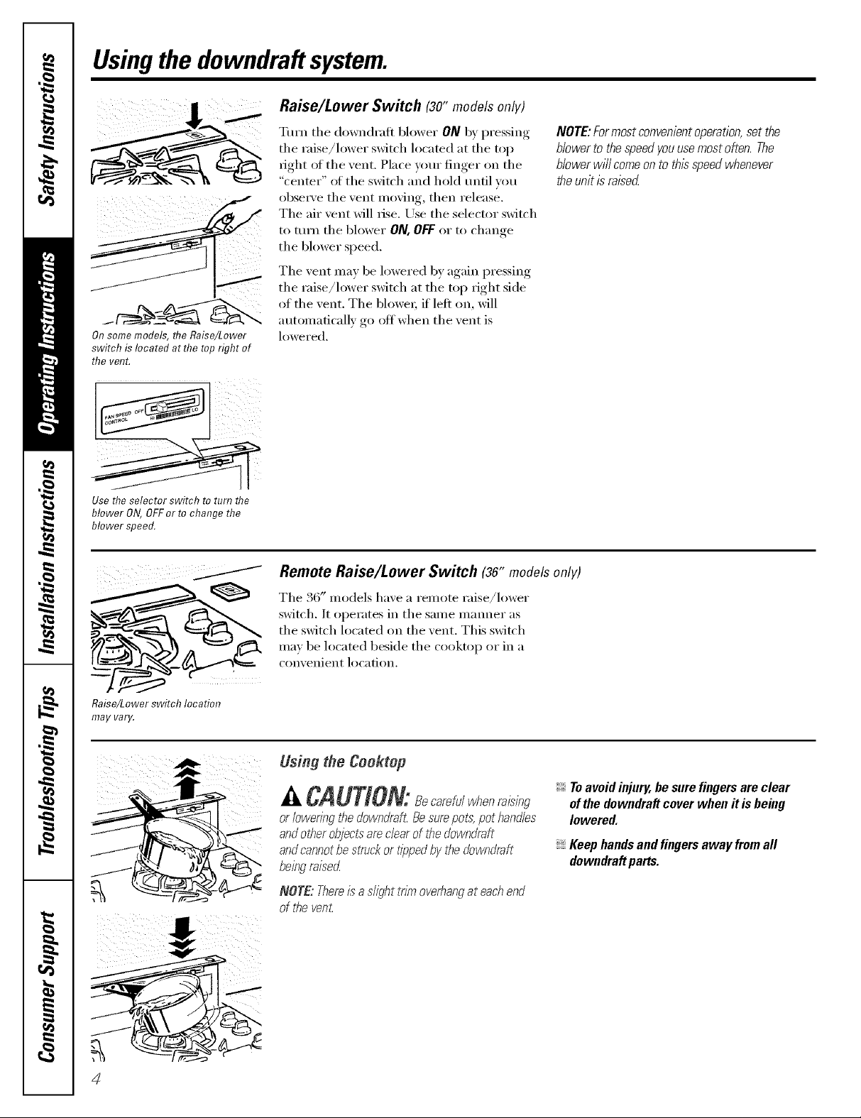
Raise/Lower Switch (3o"modelsonly)
Turn the down(h'aft blower ON b) pressing,,
the raise/lower switch located at the top
fight of the vent. Place your finger on the
"center" of the switch and hold until _ou
obse_a'e the vent moving, then release.
The air vent will rise. Use the selector switch
to ttlrn the blower ON,OFFor to change
the blower speed.
The vent may be lowered by again pressing
the raise/lower switch at the top right side
of the vent. The blowex; it left on, will
automatically go off when the vent is
On some models, flTe Raise/Lower
switchis locatedatthetoprightof
thevent.
lowered.
NOTE:Formostconvenientoperation,setthe
blowerto thespeedyouusemostoften.The
blowerwi//comeonto thisspeedwhenever
theunitisraised
Use the selector switch to turn the
blower ON, OFFer to change the
blower speed.
Raise/Lowerswitch location
may varg.
Remote Raise/Lower Switch (36" modelsonly)
The 36" models have a remote raise/lower
switch. It operates in the same manner as
the switch located on the vent. This switch
may be located beside the cooktop or in a
convenient location,
Using the Coektop
A CAUTION:8ec ref, /whenr isin
or bwering the downdraft. Besurepot,s:pot Mnd/es
andother object:s"arechar of tile downdraft
andcannotbe struckor tipped by the downdraft
being raised
NOTE: Thereis adight trim ovebang at eachend
of tl_even£
Toavoid injury, be sure fingers are clear
ofthe downdraft cover when it is being
lowered.
Keephandsandfingersawayfromall
downdraftparts.
4
Page 5
Cooking Tips
www.GEAppliances.com
The high air moven_ent ot this down(h'att
system can increase the cooking times fi)r
some fi)o(ls. It may take hmger to reach
high cooking temperatures if the down(h'afl
is turned to high fight away. A(!iust the lira
speed tot best cooking results.
For best results when heating oil fiw deep
flTing or when boiling wateL use the fl'ont
surti_ce units or wait until the water is
boiling or the oil is at ti'ying mml)emtm'es
before turning on the (h)wndratt.
Thedown&aft may not completely captureall the
steam frompanson thefront burners.
Careand cleaning ofthe downdraftsystem.
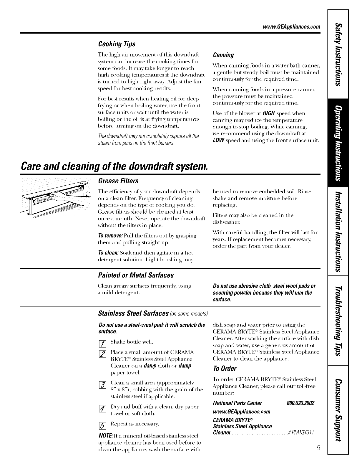
Grease Filters
The eflicienc)of _om" downdralt depends
on a clean filte_: Frequency of cleaning
del)ends on the t},I)e of cooking )ou do.
(;tease tilte_ should be cleaned at least
once a month. Never operate the downdrafl
without the filte_s in place.
Toremove: Pull the filte_s out by grasping
them and pulling straight up.
Toclean: Soak and then agitate in a hot
(lete_gent solution. I,ight brushing may
Canning
When canning fi)ods in a wate_q)ath canne_;
a gentle ])tit stead)' boil m list be maintained
continuously fi)r the required time.
When canning toods in a pressure canne_;
the pressure illtlst be maintained
continuously for the required time.
Use of the blower at HIGHspeed when
canning may reduce the temperature
enough to stop boiling. While canning,
we _ecommend using the down(h'alt at
LOWspeed and using the fl'ont SUll'ilce unit.
be used to remove embedded soil. Rinse,
shake and remove moisture befi)re
replacing.
Filters may also be cleaned in the
dishwasher:
X_\]th carefifl handling, the filter will last fi)r
yem_. If replacement becomes necessm T,
order the part ti'om your (leale_:
Painted or Metal Surfaces
Clean greasy surti_ces ti'equently, using
a mild detergent.
Stainless Steel Surfaces (onsomemode/s)
Donotusea steel-woolpad;it will scratchthe
surface.
[] Shake bottle well.
[] Place a <small alllOt/nt of CEIL_dVIA
BRYTE _'Stainless Steel Appliance
Cleaner on a damp ch)th or damp
paper towel.
[] Clean a small area (approximately
8" x 8"), rubbmg wKh the g_am of the
stainless steel if api)licable.
[] Dr) and buff with a clean' dr) I)al)er
towel or sott cloth.
[] Repeat as necessm_.
NOTE:If a mineral oil4)ased stainless steel
al)pliance cleaner has been used befi)re to
clean the appliance, wash the surfi_ce with
Do not useabrasive cloth, steel wool pads or
scouring powder because they will mar the
surface.
dish soap and water prior to using the
CEIL_JA BRYTE ') Stainless Steel Appliance
Cleane_: _Mter washing the surfi_ce with dish
soap arid wateI; rise a generotls }li//otlnt ot
CEIL_4A BRYTE <'_Stainless Steel Appliance
Cleaner to clean the appliance.
To Order
To order CEIL_dX4ABRYTE <':Stainless Steel
Appliance Cleane_; please call ore" toll-ti'ee
ntllllbeY:
National Parts Center 800.626.2002
www.GEAppliances.com
CERAMABRYTP _
Stainless Steel Appliance
Cleaner ....................... _ PM]O)(3] ]
Page 6

Installation
Downdraft Vent
Instructions
mfyou have questions, call 800.GE.CARES or visit our Website at: www.GEAppliances.com
BEFORE YOU BEGIN
Read these instructions completely and
carefully.
• IMPORTANT - Savethese
instructions for local inspector's use.
• IMPORTANT - Observeall
governing codes and ordinances.
• Note to Installer - Be sure to leave these
instructions with the Consumer.
• Note to Consumer - Keep these
instructions for future reference.
• Note - This appliance must be properly
grounded.
• Proper installation is the responsibility of
the installer.
• Product failure due to improper installation
is not covered under the Warranty.
System
REMOVE PACKAGING
Open the carton and remove parts package.
Check contents to be sure all pieces are
present. (The parts package may be attached
to the power cord.)
Remove the shipping materials. Remove the
carton and set aside. The carton can be used
as a pad when changing or adjusting vent
direction.
PARTS INCLUDED
TOOLS YOU WILL NEED
Flat-blade screwdriver
Carpenter square Ill
Pliers
Jig saw
Ductwork to suit
the installation
Duct tape
Stabilizing brackets
(all models) (4)
Remote raise/lower assembly (for 36" models only)
Wire box (2)
and screws (4)
Switch cover
plate (1)
Plastic strain
relief (2)
Attachment
bracket (1)
Wire and white
connector (1)
Page 7

JnstaJJation instructions
DiMENSiONS AND CLEARANCES
A CAUTION -WaUcoverings,countertops and
cabinets shouJd withstand 200°R heat generated by
any cooktop.
tt
_2
8½"
................. A ...................
4_.......
............ g ...........
7V_ 21/4- _
33/T 6_I/4," i/j,
71/8"_
101/2H
_33/d '
AWARNING!
INSTALLATION SAFETY
INSTRUCTIONS
TO REDUCE THE RISK OF FIRE, ELECTRIC
SHOCK, OR INJURY TO PERSONS, OBSERVE
THE FOLLOWING:
[]
Installation work and electric wiring
must be done by qualified person(s)
in accordance with all applicable codes
and standards, including fire-rated
construction.
[]
Ducted fans must always be vented to
the outdoors.
[]
When cutting or drilling into wall or
ceiling, do not damage electrical wiring
and other hidden utilities.
A WARNING - To reduce the risk of
fire, use only metal ductwork.
27 tt
A B
30" Models 30" 281¼"
36" Models 36" 333A"
recommended for island installations.
IMPORTANT: These vents are
Against-the-wall installations are
limited due to countertop depth
requirements. The vent and cooktop
combined depth requires an extra
deep flat countertop surface.
The countertop must be at least 26" deep
with a flat surface area of 231/2" or more, front
to back. (NOTE: JGP932S, JP350SC, JP930SC
and JP938SC require 23%" flat surface area.)
In addition, other clearances to the front
edge of the countertop must be considered.
• See specific cutout illustrations with your
cooktop model to determine requirements.
A countertop with
a raised lip or rolled
front edge may not
allow enough flat
area for installation.
/0 Flat surface
area
Page 8

mnstaaiation mnstructions
ADVANCE PLANNING
CLEARANCES
• Installation must conform with local codes.
• The downdraft system with blower, motor
and duct work will occupy the cabinet
below the countertop and cooktop,
• The blower/motor assembly can be located
below the cabinet floor. The assembly will
fit between 16" floor joists.
In this installation a transition to 6" round
is required.
• The blower motor assembly can also be
installed outdoors. Order JXBC67 for
remote blower installations outdoors.
• Refer to Dimensions and Clearances for
information on appropriate placement
and necessary clearances when planning
installation.
• Refer to your specific cooktop installation
instruction for other appropriate clearances.
• Avoid placing cabinetry directly above the
cooking surface when possible.
• If cabinetry is used above the cooking
surface:
Installation must conform with local codes.
Use cabinets no more than 13" deep.
Maintain 30" minimum clearance between
cooktop and unprotected cabinets directly
above cooktop.
If clearance is less than 30'; protect cabinet
bottoms with flame-retardant millboard at
least 1/4" thick or gypsum board at least
3/16" thick covered with 28 gauge sheet
steel or .02" thick copper,
Clearance between cooktop and protected
cabinetry must not be less than 24':
EXCEPTION: Installation of a listed
microwave oven or cooking appliance over
the cooktop shall conform to the installation
instructions packed with that appliance,
• Working areas adjacent to the cooktop
should maintain 18" minimum clearance
between countertop and cabinet bottom.
DUCTWORK
Prepare ductwork to vent to the outdoors.
Use the shortest and straightest duct run
possible.
The maximum permissible length for duct
run is 150 feet.
Refer to Duct Fittings chart to calculate
equivalent length for various duct
configurations.
• The downdraft blower system is designed
to use 31/4" x 10" ductwork. It can be
transitioned to 6" round.
• Ductwork MUST be vented to the outside i
never into a crawl space, attic or other
enclosed space.
• Determine the need for a wall cap or roof
cap. Purchase the cap in advance from
your home building center or plumbing
supply,
COOKTOP ELECTRICAL AND
GAS LOCATION
Plan the placement of the electrical outlet
and gas (if used) carefully. Gas or electrical
outlets cannot be placed on the back wall of
the cabinet because it may interfere with the
downdraft plenum.
Install a standard electrical outlet within
reach of the vents' 2 foot long power cord.
• The vent and a gas cooktop combination
can operate from the same 120V standard
duplex outlet.
• Electric cooktops must operate from
a separate 240V junction box.
REMOTE SWITCH
(for 36" models only)
The downdraft vent has a separate
raise/lower switch. Plan to install the switch
in a convenient location outside of the
vent/cooktop cutout.
Page 9

Installation Instructions
INSTALLATION POSSIBILITIES
When the kitchen design calls for an against
the wall installation, move 24" deep base
cabinet forward, 3" to 5" Filler panels can
be angled or flat to fill the space between
adjacent cabinets.
Maintain cutout clearances to front edge as specified.
Filler
JJ_ Filler panel
Base panel
cabinet Base sink
30" Min. for JVB37 and JVB94
36" Min, for JVB67 and JVB98
In an island or peninsula, the countertop can
be extra deep to provide seating opposite of
the cooktop. Adding base cabinets on each
side of the cooktop provides extra storage
and countertop work space.
i
18"i
I Base to sink
30" to 42"
18"
Countertop
overhang
per cooktop
clearances
must be
maintained
End
Cover panel
panel
Page 10

Installation Instructions
INSTALLING THE DOWNDRAFT VENT SYSTEM
30" COOKTOP/DOWNDRAFT
UN{TS JVB37 AND JVB94
NOTE: Before you begin, measure and mark
Dimension 3 to ensure that adequate flat
countertop surface is available.
Identify the cutout illustration for the cooktop
modet you are installing with this downdraft
vent system.
e Draw lines on the countertop to follow
as a cutting guide.
Make sure sides of the opening are
parallel and rear and front cuts are exactly
perpendicular (right angle) to sides.
21/8"
[] [] [] [] [] []
Overall Cooktop Surface Surface Depth Minimum Setback Combined Combined
Model No. Width Overall Depth with Downdraft* Cutout to Front Edge** Cutout Width Cutout Depth
JP326 30-1/4" 21-1/4" 23-3/8" 2-1/2" 28-1/2" 22-3/8"
JP340
JP350
J P930 29-3/4" 20-7/8" 23" 2-1/2" 28-1/2" 22-1/4"
JP931
JP938
JP939
JP350SC
JP930SC 29-7/8" 21-1/2" 23-5/8" 2-1/2" 28-1/2" 22-3/8"
JP938SC
JGP328
JGP933 30" 21" 23-1/8" 2-1/2" 28-1/2" 22-3/8"
JGP933S
JGP336 30" 21" 23-1/8" 2-1/2" 28-1/2" 22-1/4"
JGP932 29-3/4" 21" 23-1/8" 2-1/2" 28-1/2" 22-1/4"
JGP930S 30" 21-1/4" 23-3/8" 2-1/2" 28-1/2" 22-1/4"
JGP932S 29-7/8" 21-5/8" 23-3/4" 2-1/2" 28-1/2" 22-5/8"
*Includes 1/8" gap between cooktop and vent trim
**Required to maintain UL or AGA approvals
10
Page 11

Installation Instructions
36" COOKTOP/DOWNDRAFT
UNITS JVB67 AND JVB98
NOTE: Before you begin, measure and mark
Dimension 3 to ensure that adequate flat
countertop surface is available.
Identify the cutout illustration for the cooktop
model you are installing with this downdraft
vent system.
• Draw lines on the countertop to follow
as a cutting guide.
• Make sure sides of the opening are
parallel and rear and front cuts are
exactly perpendicular to sides.
21/8t_
[] [] [] [] [] []
Overall Cooktop Surface Surface Depth Minimum Setback Combined Combined
Model No. Width Overall Depth with Downdraft* Cutout to Front Edge** Cutout Width Cutout Depth
JP626 35-1/2" 21" 23-1/8" 2-1/2" 34" 21 -1/8"
JP960
JP961
JP968 36" 20-3/8" 22-1/2" 2-1/2" 34" 21-3/4"
J P969
JP960S
JP968S 36-1/8" 21" 23-1/8" 2-1/2" 34" 21-7/8"
JGP628
JGP963 36" 21" 23-1/8" 2-1/2" 34" 21-7/8"
JGP963S
JGP636 36" 21" 23-1/8" 2-1/2" 34" 21-7/8"
JGP960S 36" 21 -1/4" 23-1/8" 2-1/2" 34" 22-7/8"
J GP962 36" 20-7/16" 22-9/16" 2-1/2" 34" 21-3/4"
JGP962S 36-1/8" 21-1/16" 23-3/16" 2-1/2" 34" 22-1/8"
*Includes 1/8" gap between cooktop and vent trim
**Required to maintain UL or AGA approvals
11
Page 12

mnstaaiation mnstructions
INSTALLING THE DOWNDRAFT VENT SYSTEM
POWER SUPPLY
This downdraft vent must be supplied with
120V, 60Hz., and connected to an individual,
properly grounded branch circuit, protected
by a 15 or 20 ampere circuit breaker or time
delay fuse.
Gas Cooktops
If this vent is installed in combination with a
gas cooktop, it may operate from the same
duplex outlet.
Electric Cooktops
If this vent is installed in combination with an
electric cooktop, the vent must operate from
a separate 120V outlet.
A properly grounded 3-prong receptacle
should be located within reach of the vents'
2 foot power cord.
• Locate the receptacle inside the cabinet on
the right side wall. The receptacle cannot
be placed on the back of the cabinet wall
where it may interfere with the downdraft
plenum. See illustration.
Do not leave gas or electrical
connections within shaded area.
outlet
12" above
cabinet floor
281½" for 30" model,'
NOTE: Do not use an extension cord or
adapter plug with this appliance. Follow
National electrical codes or prevailing local
codes and ordinances.
12
Page 13

Installation Instructions
DUCTWORK LENGTH AND DUCT FiTTiNGS
NOTE: Do not exceed 150 foot maximum permissible equivalent lengths!
Flexible ducting: If flexibte metal ducting is used, all equivalent feet values in the table should be
doubled. The flexible metal duct should be straight and smooth and extended as much as possible.
DO NOT use flexible plastic ducting.
Add equivalent lengths for all duct pieces and transitions used to ensure that the duct run does not
exceed the maximum 150 feet.
31/4"x 10"
to 6" Round
6" Round 1ft. (per 31/4" x 10" 5 ft.
Straight foot length) 45° Elbow
31/4"x 10" 1ft. (per 31/4"x 10" 24ft. Wall Cap 21 ft.
Straight foot length) 90 ° Flat Elbow with Damper
6" Round 31/4" x 10"
6" 15 ft. to 31/4" x 10" 7 ft. Wall Cap 27 ft.
90° Elbow Transition with Damper
31/4"X 10"
6" to 6" Round 5 ft. 6" Round
45° Elbow Transition Roof Cap
31/4" x 10" Transition 6" Round
90° Elbow 90° Elbow Roof Vent
9 ft. 20 ft.
6" Round
to 31/4 " x 10"
16 ft. 24 ft.
20 ft.
ds
Transition
g0 ° Elbow
6" Round
12ft.
SHOULD NOT EXCEED 150 EQUIVALENT FEET
*Equivalent lengths of duct pieces are based on actual tests conducted by GE Evaluation Engineering
and reflect requirements for good venting performance. See chart for CFM Duct Length.
13
Page 14

mnstaaiation mnstructions
INSTALLING THE DOWNDRAFT VENT SYSTEM
VENTING OPTIONS
Side-to-Side Adjustments
The entire blower mounting plate can be
adjusted 31/2" to the left or right. This will help
to align vent discharge to house ductwork.
Loosen screws to adjust
blower left to right _ j ........ .....
/ i ii "_
[ /
Discharge Direction
The blower assembly may be removed and
turned 90 ° for a left or right side discharge.
• The downdraft vent is shipped with the
discharge outlet pointing straight down
and can be changed to the left or right side.
[ ,'
J
j..
To Change to a Left or Right Discharge
[] Remove the 4 screws holding the blower
to the mounting plate assembly. Retain
screws.
[]
Remove the blower assembly, turn it
over to access the 4 nuts holding the
blower to the mounting plate. Remove
the nuts.
(_ MPORTANT: Do not lift the motor
[]
Turn the blower to the left or right
discharge direction and reinstall the
4 nuts.
Discharge left Discharge right
by the power cable.
'[ ....
Discharge down
(as supplied)
• A left or right 90 ° direction adjustment
should be performed before dropping into
the countertop opening.
• Flatten the shipping box to use as a pad.
• Lay the vent on its back onto the pad.
[] Reinstall the blower and mounting plate
with original screws.
To Locate the Ductwork Holes in the Cabinet
Floor or Side Walls
[]
Temporarily, put vent into the countertop
opening.
[]
Push the vent all the way to the back of
the opening.
[]
If you are transitioning to 6" round,
place transition (obtained locally) over
the discharge outlet.
• Mark the location and remove the
assembly.
• Cut holes and install ductwork
connections.
Order JXRB67 for installation of the blower
and motor below the floor.
Order JXBC67 for installation of the blower
and motor outdoors.
14
Page 15

mnstaaiation mnstructions
[] INSTALL THE DOWNDRAFT VENT
_ _ red
\_ method
_k Secure
the upper
brackets
with screws
located on
the side
of case
and attach
to back of
cabinet
Secure the lower brackets
to blower housing
Place the downdraft vent into the
countertop cutout, against the back side.
[]
Secure the downdraft to the countertop
supplied brackets. See illustration.
Fasten 2 brackets to vent side and secure
[]
to cabinet back wall.
Install 2 brackets on the bottom of the
[]
vent. Attach brackets to slide screws on
the vent and to the floor using wood
screws (not supplied).
When installing in a tile countertop
surface, it may be necessary to apply
a locally approved caulking to cover
any gaps,
[] iNSTALL THE DUCTWORK
Use minimum 26" gauge galvanized or
24 gauge aluminum duct 31/4" x 10" or
6" round. PVC duct should be used if
installing under a poured concrete sJab.
DO NOT USE flexible ducfing.
Always use appropriate roof or wail
cap with damper. Laundry type wail
caps shouJd never be used. See the
Ductwork Length and Duct FJtdngs
chart.
o
Use the straightest duct run possible.
@
For satisfactory performance the duct
run shouJd not exceed 150 feet or its
equivalent tength when bends or
various fittings are used. Refer to the
tame of equivaJent tengths to calculate
your installation.
i Duct tape over
seam and screw
Airflow
i
Screw
, install ductwork so the piece of duct
nearest the downdraft unit slots iNTO
the next piece of the duct. Secure the
joints with self-tapping screws and
apply duct tape around the joints to
ensure an airtight seat.
15
Page 16

mnstaaiation mnstructions
INSTALLING THE DOWNDRAFT VENT SYSTEM
[] iNSTALL THE RAiSE/LOWER
NOTE: Stop 3 is for 36" models onmy.
Skip this stop if installing a 30" model.
-4,WARNING - Disconnectelectrical
power from the unit before beginning switch
installation. Failure to do so could result in
personal injury or damage to the electrical
controls.
NOTE: Determine the location for the
Raise/Lower switch. The wiring lead is
68" tong.
Raise/Lower
switch
Mounting
bracket
i
i
i
i
_!_'3/8" Hole
[]
Remove protective film from the top of
the switch trim.
[]
Peel film from the adhesive strips on the
back of the switch trim. Thread the wire
lead through the mounting bracket and
countertop. Press trim over the mounting
bracket to set the adhesive.
Connect Raise/Lower Wire Lead to Wire Box
[] Thread wire end with the connector
through the hole on the end of a wire
box. Pull approximately 3" additional
wire length beyond the open end of
the box.
[] Connect the mating wire connectors.
[] Install the wire box onto the bottom of
the countertop or directly behind the
switch. Use screws or adhesive
appropriate for the type of countertop.
[] Place plastic strain relief over the wire,
just outside of the hole at the end of the
wire box. Do not pinch or twist the wire.
Snap the strain relief closed and press
into the hole.
connector
relief
[] Drill a 3/'8" hole into the desired
location. Use the mounting bracket
as a template to locate the hole
accurately. Check for interference
between the switch cover, adjacent
objects and cooktop/vent overlaps.
[] tf switch is mounted into a tile
surface, drilt the hole between tiles.
Use locally approved caulking to
cover any gaps.
[] Center the mounting bracket over the
hole and mark pilot holes. Remove
and drill holes according to type of
countertop.
[] Mount the metal switch bracket
with screws (not provided). Choose
screws for your type of countertop
or use locally approved adhesive.
Control box I/ _i-!11.:¢_.._ _ -'_
Connect Wire Lead t t
[] Thread the long 68" wire lead through
the end of the other wire box.
[] Push wire leads into the white connector
provided.
[] Push wire connector into the mating
connector on the control box. Install the
wire box onto the end of the control box
with screws provided.
[] Place plastic strain relief over the wire,
just outside of the hole at the end in the
wire box. Do not pinch or twist the wire.
Snap the strain relief closed and press
into the hole.
[] Coil the excess wire and position away
from moving parts and cabinet contents.
16
Page 17

Installation Instructions
[] CONNECT THE POWER
Plug power cord into a properly grounded
receptacle.
INSTALL THE COOKTOP
• With the downdraft in the "down" position,
place the cooktop into the cutout.
• Push the cooktop back until the back edge
of the cooktop just barely touches the front
edge of the downdraft cover.
• Using a dime as a thickness gauge, align
the cooktop so that there is a minimum
uniform gap of 0.05" (the thickness of
a dime) between the cooktop and the
downdraft cover.
NOTE: Do not force the downdraft cover to
move rearward when aligning the cooktop.
This may cause the downdraft cover to
impact and damage the cooktop when the
vent is raised and lowered.
NOTES:
• Accurate alignment of cooktop and
downdraft is necessary to ensure that there
is no interference when air vent is raised
and lowered. There should be a gap of
0.05" (the thickness of a dime) between the
back edge of the cooktop and the front
edge of the downdraft cover.
OPTIONAL KiTS
JXRB67 optional accessory for #)door remote
location of the blower,/motor assembly. Use
this kit when the blower and motor assembly
witI be located below the cabinet floor.
MoL ring
brackets
JXBC67 optional outdoor cover accessory
for remote installation of blower and motor
assembly on an outside watt.
• Radiant cooktop cannot be flush mounted
when using this downdraft vent.
/
17
Page 18

Beforeyoucall forservice...
Troubleshooting -tips
Save time and money/.Review the chart below first
and you may not need to call for service.
i Possible Causes What To Do
Fan does not work The vent is not fully extended. * Press tile Raise/Lower switch.
The blower control switch * Slide it to tile right.
may be in the OFFposition.
Vent does not rise Vent not plugged into an outlet. * Plug vent into a 120V power outlet.
Raise/Lower switch did not * Hold switch down fin" a couple of seconds to
engage lift motor, actiwlte motor.
Circuit breaker may have * Check circuit breaker. Reset it necessary.
tripped.
Remote switch not plugged in. * Check all connections between the remote switch
and vent body.
18
Page 19

GEDowndraftSystemWarranty.
All warranty service provided by our Factory Service Centers,
or an authorized Customer Care®technician. Toschedule service,
on-line, 24 hours a day, visit us at www.GEAppliances.com, or
call 800.GE.CARES (800.432.2737).
Staple your receipt here.
Proofof the original purchase
date is needed to obtain service
under the warrant_
GEWill Replace:
Anypattof the downdraft system which fails due to a defect in materials or workmanship.
Fromthedateof the
origina!purchase
i ii iiiff i i i !_iii! iDii iliiiliii!i iiii iiiiiii
Service trips to your home to teach you how to use
the product.
Improper hlstallation, delivery or mah_tenm_ce.
Failure of the product if it is abused, misused,
or used for other thml the intended purpose or
used commerciaJly.
Replacement of the replaceable filters.
This warranty is extended to the original purchaser and any succeeding owner for products purchased for home
use within the USA. In Alaska, the warranty excludes the cost of shipping or service calls to your home.
During this full one-year warranty, GE will also provide, free of charge, all labor and in-home
service to replace the (lefective part.
iiiili!Replacement of house fuses or resetting of circuit
breakers.
iiiilii!Damage to the product caused by accident, fire, floods
or acts of God.
iiiili!h_cidentaJ or consequential damage caused by possible
defects with this applimlce.
Dmnage caused after delivery.
Some states do not allow the exclusion or limitation of incidental or consequential damages. This warranty gives
you specific legal rights, and you may also have other rights which vary from state to state. Toknow what your
legal rights are, consult your local or state consumer affairs office or your state's Attorney General.
If you have an installation problem, contact your dealer or installer. Youare responsible for providing adequate
electrical, gas, exhausting and other connecting facilities as described in the Installation Instructions provided
with the product.
Warrantor:General Electric Company.Louisville,KY 40225
19
Page 20

ConsumerSupport.
6EApp/iancesWebsite www.GEApp/iances.cem
Ha_e a (plest]o]_ or _eed assistm_ce wkh your apphauce? Try the (}E Appl]aN_ces Website 24 hems a day.
am_y day of the year! For greater c(mvem_ie]_ce amid {i_ster sePdce, )oil can now dowi_]oad Owi_er's Mamla]s,
order parts, catalogs, or e', el/schedule service on-Him/e. Yell cam/also "Ask Our Team of Experts ......
Vollr (]lies[iota/s, amid so m]/llCh more...
Schedu/e Serw;ce mw GEApp/iances.com
Expert (;E repair se]_,_ice is o]]h, o]_e seep awa',' {_'om _,our doon (;eC o]_-lim_e and sc]]edu]e _,our service ac
xour, com'en i en ce 24 h ours _?r (1_?' of the ?rea 1"!()Y ca]] SO0.1 ;E.( :Z_RES ( SO0.432.2737) duri m_g m_urma]
H)10sim/ess h(]10]s.
flea/Life Des,;gnStudio www.CE@plia.ces.com
GE slq_purCs d_e [ Im_iversal Design com_cepc-produccs, services m_d envirom]]encs chac cam_ be used bv
people of a]] ages, sizes amid capabi]ides. We recognize die m_eed to design fin" a wide nmge o{ ph}_ica] m_d
m e m_Ca] abi]i des a _ d im pai rm encs. Fur derails of GE's [ in_iversa] Design a pp]i ca d on s, i_ c] _di _ g ]d cchen
design ideas %r people _rdt]_ disab]]kies, d_eck ouC our Webs]ce cedar. Fur cite heari_g h_paired, []]ease ca]]
S00.TDD.(;EAC (800.833.4322).
ExtendedWarranties m v GEAppfiances.com
is still i_ effect. _'ou can_ purd_ase it (m-]i_e m_ytime, or ca]] S00.621L2224 duri_g nom_al b_si_ess hours.
(;E C] m s_m_ er Hom e Servi c es wi]] sd]] be ch e]'e a_er )o _u" wa rra _ b expi res.
Parts and Accessories m v GE pp/iances.com
}[]]dhidua]s qualified co se_ice d_eir _r_ _)[)]i_CeS C;_ ha_e []arCs or accessuries se]_C directly co their homes
(VISA, MasterCard a_d Discover cards are accepted). Order on-li_e coda 5 24 hours e_ ery (lay or by phoebe
at 800.626.2002 dmi_g normal bush_ess hours.
_nstruotie_s oe_taineff in this mantra/oover preoedures to he performed by a_y use_, Other set_ioinff ffenera//y
shmdd he referred to qua/ified service personnel Ca_tien must he exer_beg Mnoe improper se_fioing may cause
tmeMe operation.
ontact Us wmw.GE pp/iances, com
[_ _o_ are _oC sadsfied _rdt]] Cite service _o_ receive [_'om GE, contact us (m our WebsiCe _rd_]_ _]] d_e details
i_c]udh_g your phone mm_be_; or w_Jce to: (;enend Manage_; (5_scomer Reladons
GE App]im_ces, Appliaure Park
I ,ouisvi]]e, KY 40225
RegisterYourApp/iance www.GEAppiiances.cem
Register your new appliance on=line-at your eolivel_enee! Timely [>ro(l!ur[ reg]sCmdon,, wi]] allow [br
enha_?ced commlmicacio]? al/d pr]mlpc service imder tile terms of_ol0]" _r_I']_][_;' S]?()II](] tile _?eed arise.
'_i_u ma',' also mail i_ d_e [_re-[_ri_ced regiscrado_, card i_ch_ded i_ cite [_ac]d_g_ material.
20 Printed in the United States
 Loading...