How it Works
Log In / Sign Up
Buy Points
How it Works
FAQ
Contact Us
Questions and Suggestions
Users
GE
Loading...
J
JV930SCBR
4
JV935
JV935D
JV935D1BB
JV935D1CC
JV935D1WW
JV936
9
JV936D
JV936D1SS
JV936DSS
2
JV960
6
JV960SASS
JV960SCBR
5
JV965
3
JV965D
JV965D1BB
JV965D1CC
2
JV965D1WW
2
JV965DWW
JV966
9
JV966D
JV966D1SS
JV966DSS
5
JVB34
JVB35
2
JVB36
2
JVB36WBB
JVB36WWW
JVB37
3
JVB37A
JVB37ABB
2
JVB37ACC
2
JVB37AWW
2
JVB37H1BB
JVB37H1CC
JVB37H1WW
JVB37HBB
2
JVB37HCC
JVB37HWW
JVB64
2
JVB65
2
JVB66
3
JVB67
7
JVB67A
JVB67ABB
JVB67ACC
JVB67AWW
JVB67H1BB
JVB67H1CC
JVB67H1WW
JVB67HBB
3
JVB67HCC
JVB67HWW
JVB93
2
JVB93SA
JVB93SASS
JVB94
5
JVB94H1SS
JVB94SH
JVB94SH1SS
JVB94SHSS
2
JVB96
3
JVB96SA
JVB96SASS
JVB98
5
JVB98H1SS
JVB98SH
JVB98SH1SS
JVB98SHSS
2
JVC3300
JVC3300J1SA
JVE40
2
JVE40DT1BB
JVE40DT1WW
JVE40DTBB
4
JVE40DTWW
2
JVE40ST1SS
JVE40STSS
3
JVIWW
2
JVM1090
JVM1190
Jvm1190ay004
Jvm1190ay01
Jvm1190ay02
Jvm1190ay03
Jvm1190bd001
JVM1190BY
Jvm1190by003
Jvm1190by01
Jvm1190by02
JVM1190CB
Jvm1190sd001
JVM1190SY
Jvm1190sy001
Jvm1190sy002
Jvm1190sy01
JVM 1660
2
JVM 1661
JVM 192K
2
JVM 45
Loading...
Loading...
Nothing found
JVB67HBB
Installation Instructions Manual
13 pgs
250.6 Kb
0
Owner's Manual & Installation Instructions
40 pgs
762.59 Kb
0
Specification
3 pgs
203.75 Kb
0
Table of contents
Loading...
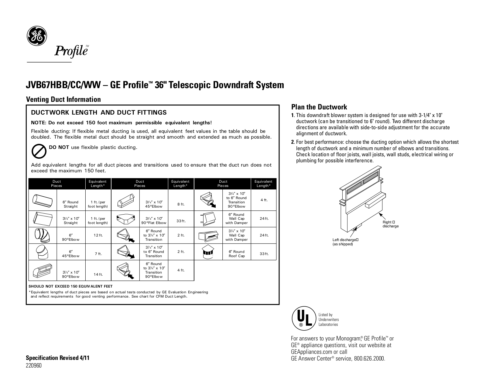
GE JVB67HBB, JVB67HCC, JVB67HWW Specification
...
GE Specification
Download
Specifications and Main Features
Frequently Asked Questions
User Manual
Download
Loading...
+
hidden pages
Unhide
You need points to download manuals.
1 point = 1 manual.
You can buy points or you can get point for every manual you upload.
Buy points
Upload your manuals
 Loading...