

Page 1

Range Hoods
Vented
ge.com
Patent No.: US D450, 829S 626851C 49-80391 12-05 JR
Safety Information . . . . . . . . . . 3
Operating/Care and Cleaning Instructions
Charcoal Filters . . . . . . . . . . . . . .5
Grease Filters . . . . . . . . . . . . . . . .4
Hood Lights . . . . . . . . . . . . . . . .5
Hood Surfaces . . . . . . . . . . . . . . .5
Stainless Steel Surfaces . . . . . . . .5
Vent Controls . . . . . . . . . . . . . . .4
Installation Instructions . . .6–14
Consumer Support
Product Registration . . . . . . . . . .2
Consumer Support . . . Back Cover
Warranty . . . . . . . . . . . . . . . . . . 15
JV535
JV536
JV565
JV566
JV635
JV636
JV665
JV666
Owner’s Manual
and Installation
Instructions
Page 2
2
Operating Instructions Safety InstructionsConsumer Support Installation Instructions
Inside you will find many helpful hints on how to use and maintain your range hood properly.
Just a little preventive care on your part can save you a great deal of time and money over the
life of your range hood.
READ THIS MANUAL
FOR YOUR RECORDS
Write the model and serial numbers here:
#
#
You can find them on a label on the back wall of the hood.
Staple sales slip or cancelled check here.
Proof of the original purchase date is needed to obtain service under the warranty.
If you do need service, you can relax knowing help is only a phone call away. A list of toll-free
customer service numbers is included in the back section of this manual.
OR
Visit our Website at: ge.com
IF YOU NEED SERVICE
IMPORTANT!
Fill out the Consumer Product Registration Card.
Two easy ways to register your appliance!
■ Through the internet at ge.com
■ Complete and mail the enclosed Product Registration Card
GE & You, A Service Partnership.
Page 3

READ AND FOLLOW THIS SAFETY INFORMATION CAREFULLY.
READ AND SAVE THESE INSTRUCTIONS
SAFETY PRECAUTIONS
3
Installation Instructions Consumer SupportSafety Instructions
Operating Instructions
IMPORTANT SAFETY INFORMATION.
READ ALL INSTRUCTIONS BEFORE USING.
WARNING – TO REDUCE THE RISK OF FIRE,
ELECTRIC SHOCK OR INJURY TO PERSONS, OBSERVE
THE FOLLOWING:
A. Use this unit only in the manner intended
by the manufacturer. If you have questions,
contact the manufacturer.
B. Before servicing or cleaning unit, switch
power off at service panel and lock the service
disconnecting means to prevent power from
being switched on accidentally. When the
service disconnecting means cannot be locked,
securely fasten a prominent warning device,
such as a tag, to the service panel.
C. Do not use this unit with any solid-state speed
control device.
D. This unit must be grounded.
CAUTION – For general ventilating use
only. Do not use to exhaust hazardous or explosive
materials and vapors.
WARNING – TO REDUCE THE RISK OF
INJURY TO PERSONS IN THE EVENT OF A RANGE
TOP GREASE FIRE, OBSERVE THE FOLLOWING*:
A. SMOTHER FLAMES with a close-fitting lid,
cookie sheet or metal tray, then turn off the
burner. BE CAREFUL TO PREVENT BURNS.
If the flames do not go out immediately,
EVACUATE AND CALL THE FIRE
DEPARTMENT.
B. NEVER PICK UP A FLAMING PAN—
You may be burned.
C. DO NOT USE WATER, including wet
dishcloths or towels—a violent steam explosion
will result.
D. Use an extinguisher ONLY if:
1. You know you have a Class ABC
extinguisher, and you already know how
to operate it.
2. The fire is small and contained in the
area where it started.
3. The fire department is being called.
4. You can fight the fire with your back to
an exit.
* Based on “Kitchen Firesafety T
ips” published
by NFPA.
WARNING – TO REDUCE THE RISK OF
A RANGE TOP GREASE FIRE:
A. Never leave surface units unattended at high
settings. Boilovers cause smoking and greasy
spillovers that may ignite. Heat oils slowly on
low or medium settings.
B. Always turn hood ON when cooking at high
heat.
C. Do not flame foods on the cooktop. If you do
flame foods under the hood, turn the fan on.
D. Clean ventilating fans frequently. Grease
should not be allowed to accumulate on fan or
filter.
E. Use proper pan size. Always use cookware
appropriate for the size of the surface element.
WARNING – TO REDUCE THE RISK OF FIRE,
ELECTRIC SHOCK OR INJURY TO PERSONS, OBSERVE
THE FOLLOWING:
A. Installation work and electrical wiring must be
done by qualified person(s) in accordance with
all applicable codes and standards, including
fire-rated construction.
B. Sufficient air is needed for proper
combustion and exhausting of gases through
the flue (chimney) of fuel burning equipment
to prevent back drafting. Follow the heating
equipment manufacturer’s guideline and safety
standards such as those published by the
National Fire Protection Association (NFPA),
and the American Society for Heating,
Refrigeration and Air Conditioning
Engineers (ASHRAE), and the local
code authorities.
C. When cutting or drilling into wall or ceiling, do
not damage electrical wiring and other hidden
utilities.
D. Ducted fans must always be vented to the
outdoors.
WARNING –
TO REDUCE THE RISK OF FIRE,
USE ONLY METAL DUCTWORK.
■ Do not attempt to repair or replace any part of
your hood unless it is specifically recommended
in this guide. All other servicing should be
referred to a qualified technician.
Page 4
4
Operating Instructions Safety Instructions
Consumer Support
Installation Instructions
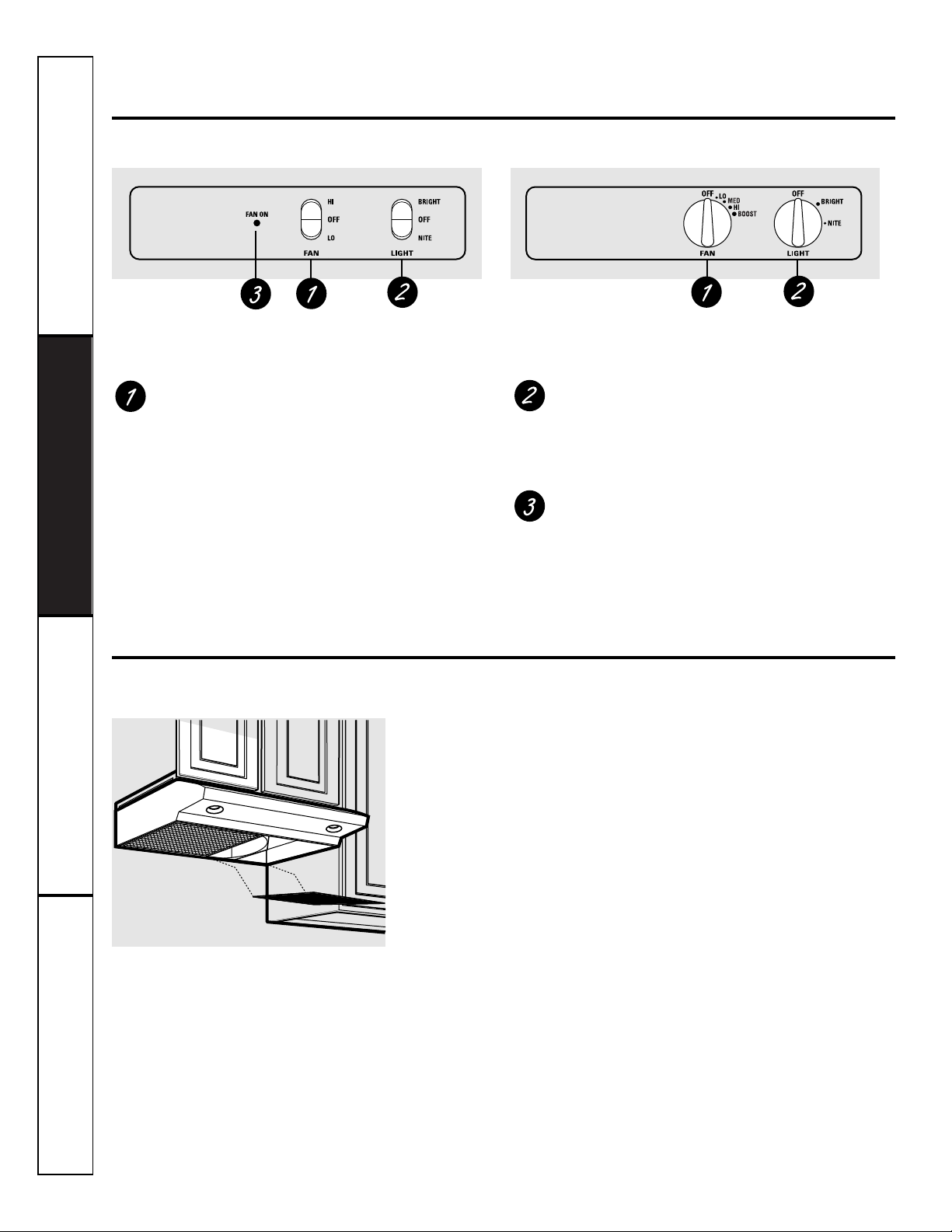
Using the hood controls.
Throughout this manual, features and appearance may vary from your model.
FAN Control
Turn or press (according to your model) the FAN
speed control to LO, MED, HI or BOOST, as needed.
Continuous use of the fan system while cooking
helps keep the kitchen comfortable and less
humid. It also reduces cooking odors and soiling
moisture that create a frequent need for cleaning.
LIGHT Control
Turn or press (according to your model) the
LIGHT control to BRIGHT for bright light while
cooking. Turn or press to NITE for use as a night
light.
FAN ON Light
The FAN ON indicator light will glow when the
fan is turned on.
Your model will have one of the above type of controls.
Care and cleaning of the vent hood.
Be sure electrical power is off and all surfaces are cool before cleaning or servicing any part of the
vent hood.
The hood has 2 metal reusable
grease filters.
The metal filters trap grease
released by foods on the cooktop.
They also help prevent flaming
foods on the cooktop from
damaging the inside of the hood.
For this reason, the filters must
ALWAYS be in place when the
hood is used. The grease filters
should be cleaned once a month,
or as needed.
To remove, slide the filters to
the rear using the tab. Pull them
down and out.
To replace, slide the filters in
the frame slot on the back of
the opening. Push up and back
and then to the front to lock
into place.
To clean the grease filters, soak
them and then swish them around
in hot water and detergent.
Don’t use ammonia or ammonia
products because they will darken
the metal. Do not use abrasives or
oven cleaners. Light brushing can
be used to remove embedded dirt.
Rinse, shake and let them dry
before replacing. They may
also be cleaned in an automatic
dishwasher.
NOTE: Before cleaning, make sure the
charcoal filters, if present, are unclipped
and removed. See the Charcoal Filters
section.
Reusable Metal Grease Filters
If it ever becomes necessary to replace
the metal grease filters, they may be
ordered from your GE supplier.
Page 5

5
Installation Instructions
Consumer Support
Safety Instructions Operating Instructions
To clean the hood surface, use a hot,
damp cloth with a mild detergent
suitable for painted surfaces. Use a
clean, hot, damp cloth to remove
soap. Dry with a dry, clean cloth.
Do not use steel-wool pads or other
abrasive cleaners. They will scratch
the surface. Wipe with a clean, hot,
damp cloth after using cleansers.
Painted Surfaces
(on some models)
Do not use a steel wool pad; it will scratch
the surface.
To clean the stainless steel surface,
use warm sudsy water or a stainless steel
cleaner or polish. Always wipe the
surface in the direction of the grain.
Follow the cleaner instructions for
cleaning the stainless steel surface.
To inquire about purchasing stainless
steel appliance cleaner or polish, or to
find the location of a dealer nearest
you, please call our toll-free number:
National Parts Center
1.800.626.2002
ge.com
Stainless Steel Surfaces
(on some models)
This hood requires two bulbs (not
included), maximum 50 watts.
Purchase and install PAR20, 50 W
Maximum halogen bulbs.
When replacing a bulb, let it cool
first. Make sure that power to the
light has been turned off. Never
allow a hot bulb to come into
contact with water.
To change the light bulbs:
Grasp the bulb on the edges and
unscrew it.
Replace with the same size bulb.
CAUTION:
■ Do not touch the hood light bulbs when they
are on. They may be hot enough to cause
injury.
■ The light bulbs operate at extremely high
temperatures. If they shatter, the hot glass
could cause personal injury.
Hood Lights
If the model is not
vented to the outside, the
air will be recirculated
through disposable
charcoal filters that help
remove smoke and
odors.
The charcoal filters
should be replaced when
they are noticeably dirty
or discolored (usually
after 6 to 12 months,
depending on hood
usage).
NOTE: DO NOT rinse, or
put charcoal filters in an
automatic dishwasher.
Charcoal Filters
(on some models)
The charcoal filters
cannot be cleaned. They
must be replaced.
For 30 ″ hood models, order
Kit no. WB02X10707.
For 36 ″ hood models, order
Kit no. WB02X10708.
These kits can be ordered
from your GE supplier.
The charcoal filters are clipped inside
of each reusable metal grease filter.
Page 6
BEFORE YOU BEGIN
6
Installation
Range Hood
Instructions
Models JV535 JV635
JV536 JV636
JV565 JV665
JV566 JV666
Read these instructions completely and carefully.
•
IMPORTANT – Save these
instructions for local inspector’s use.
•
IMPORTANT – Observe all
governing codes and ordinances.
• Note to Installer – Be sure to leave these
instructions with the Consumer.
• Note to Consumer – Keep these instructions
for future reference.
• Skill level – Installation of this appliance requires
basic mechanical and electrical skills.
• Completion time – 1-3 hours
• Proper installation is the responsibility of the
installer.
• Product failure due to improper installation is not
covered under the Warranty.
• Use only with approved cord kit, JXHC1.
NOTE: Read the ductwork sections only if you do not
have existing ductwork. If you have existing ductwork,
skip to the “Damage” section and proceed.
The venting system must exhaust to the outside.
This hood can be vented vertically through upper
cabinets or horizontally through an outside wall.
Ductwork is not included.
Exhaust connection:
The hood exhaust has been designed to mate with
standard 31⁄4″ x 10″ rectangular ducting or 7″ diameter
round ducting.
If a 6″ round duct is required, a rectangular-to-round
transition adaptor must be used*. Do not use less than
a 6″ diameter duct.
Maximum duct length:
For satisfactory air movement, the total duct length
of a 31⁄4″ x 10″ rectangular, 6″ or 7″ diameter round
duct should not exceed 65 equivalent feet.
NOTE: It’s important that ducting be installed using
the most direct route and with as few elbows as possible.
This ensures clear venting of exhaust and helps prevent
blockages. Also, make sure dampers swing freely and
nothing is blocking the ducts.
Elbows, transitions, wall and roofcaps, etc.,
present additional resistance to airflow and are
equivalent to a section of straight duct longer than their
actual physical size. When calculating the total duct
length, add the equivalent lengths of all transitions and
adaptors plus the length of all straight duct sections. The
charts on the following pages show you how to calculate
total equivalent ductwork length using the approximate
feet of equivalent length of some typical ducts.
* IMPORTANT: If a rectangular-to-
round transition adaptor is used, the
bottom corners of the damper will
have to be cut to fit, using the tin
snips, in order to allow free
movement of the damper.
Equivalent lengths of duct pieces
are based on actual tests and reflect
requirements for good venting
performance with any hood.
DUCTWORK REQUIREMENTS
WARNING – Before beginning the
installation, switch power off at service panel and lock
the service disconnecting means to prevent power
from being switched on accidentally. When the service
disconnecting means cannot be locked, securely
fasten a prominent warning device, such as a tag,
to the service panel.
FOR YOUR SAFETY:
Questions? Call 1.800.GE.CARES or visit our Website at: ge.com
Page 7
7
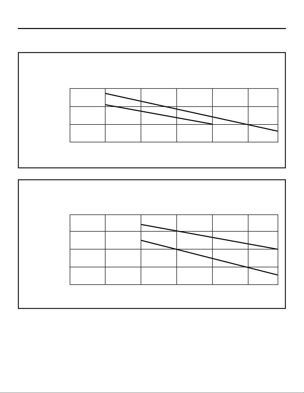
DUCTING CHART—JV5 Series Models
DUCTING CHART—JV6 Series Models
Equivalent Length in Feet
0 25 50 75 100 125 150
31⁄4″ x 10″ Rectangular Transition to 6″ Round = 4.5 ft.
7
″ Round 90° Elbow = 8 ft.
7
″ Roof Cap = 30 ft.
250
200
150
100
Air Volume in CFM
31⁄4″ x 10″
Rectangular
7″ Round
•
•
•
•
•
•
•
•
•
Equivalent Length in Feet
0 25 50 75 100 125 150
31⁄4″ x 10″ Rectangular Transition to 6″ Round = 4.5 ft.
7
″ Round 90° Elbow = 8 ft.
7
″ Roof Cap = 30 ft.
400
350
300
250
200
Air Volume in CFM
31⁄4″ x 10″
Rectangular
7″ Round
•
•
•
•
•
•
•
•
•
•
•
Follow the guidelines for proper duct sizing in the ducting charts.
Installation Instructions
MAXIMUM DUCT LENGTH: For satisfactory air movement, the total duct length of a 31⁄4″ x 10″ rectangular,
6″ or 7″ diameter round duct should not exceed 65 equivalent feet.
Page 8
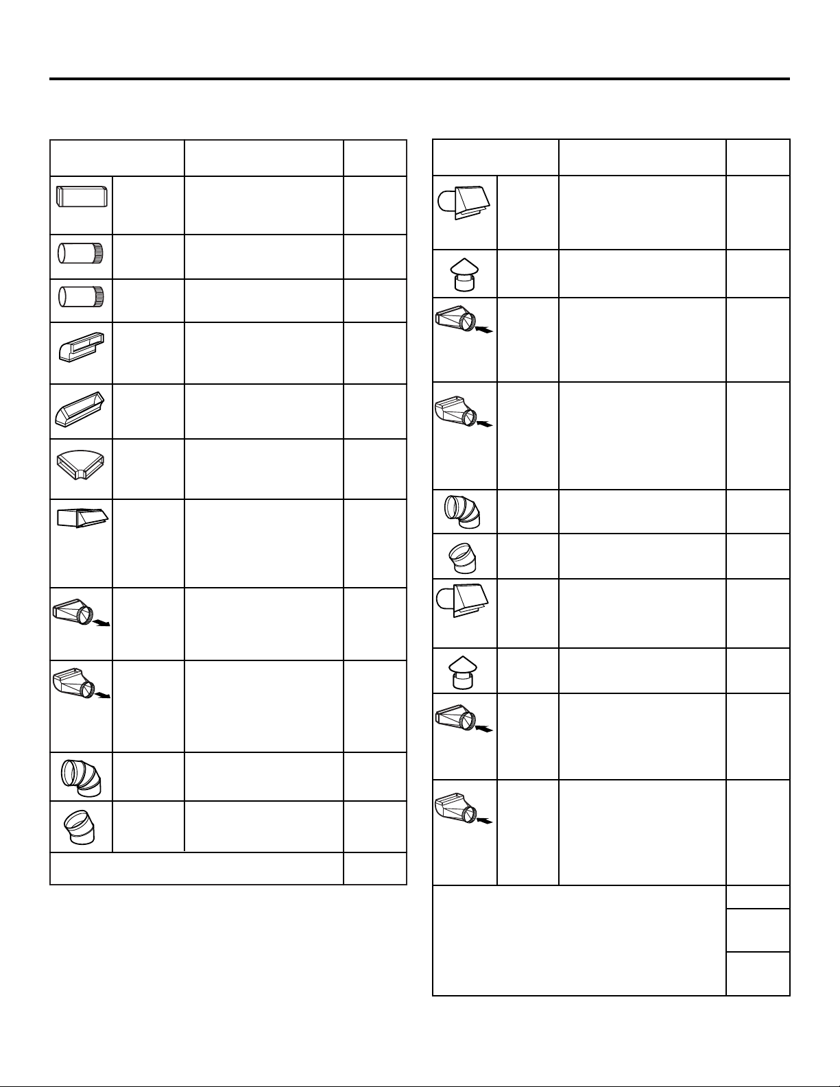
DUCT EQUIVALENT NUMBER
PIECES LENGTH x USED = TOTAL
31⁄4″ x 10″ 1 Ft. x ( ) = Ft.
Rect.,
straight
7″ Round, 1 Ft. x ( ) = Ft.
straight
6″ Round, 1 Ft. x ( ) = Ft.
straight
31⁄4″ x 10″ 8.5 Ft. x ( ) = Ft.
Rect. 90°
elbow
31⁄4″ x 10″ 7 Ft. x ( ) = Ft.
Rect. 45°
elbow
31⁄4″ x 10″ 24 Ft. x ( ) = Ft.
Rect. 90°
flat elbow
31⁄4″ x 10″ 45 Ft. x ( ) = Ft.
Rect.
(7 ft. w/o
wall cap
damper)
x ( ) = Ft.
with
damper
31⁄4″ x 10″ 4.5 Ft. x ( ) = Ft.
Rect. to
6″ round
transition
31⁄4″ x 10″ 11.5 Ft. x ( ) = Ft.
Rect. to
6″ round
transition
90° elbow
6″ Round, 8 Ft. x ( ) = Ft.
90° elbow
6″ Round, 6.5 Ft. x ( ) = Ft.
45° elbow
Subtotal column 1 = Ft.
8
WORKSHEET—CALCULATE TOTAL EQUIVALENT DUCTWORK LENGTH
DUCT EQUIVALENT NUMBER
PIECES LENGTH x USED = TOTAL
6″ Round 34 Ft. x ( ) = Ft.
wall cap
(6 ft. w/o
with
damper)
x ( ) = Ft.
damper
6″ Round 30 Ft. x ( ) = Ft.
roof cap
6″ Round 5.5 Ft. x ( ) = Ft.
to
31⁄4″ x 10″
rect.
transition
6″ Round 14.5 Ft. x ( ) = Ft.
to
31⁄4″ x 10″
rect.
transition
90° elbow
7″ Round, 8 Ft. x ( ) = Ft.
90° elbow
7″ Round, 6.5 Ft. x ( ) = Ft.
45° elbow
7″ Round 34 Ft. x ( ) = Ft.
wall cap (
6 ft. w/o
with
damper)
x ( ) = Ft.
damper
7″ Round 30 Ft. x ( ) = Ft.
roof cap
7″ Round 5.5 Ft. x ( ) = Ft.
to
31⁄4″ x 10″
rect.
transition
7″ Round 14.5 Ft. x ( ) = Ft.
to
31⁄4″ x 10″
rect.
transition,
90° elbow
Subtotal column 2 = Ft.
Subtotal column 1 = Ft.
Total ductwork = Ft.
Installation Instructions
MAXIMUM DUCT LENGTH: For satisfactory air
movement, the total duct length of a 31⁄4″ x 10″
rectangular, 6″ or 7″ diameter round duct should
not exceed 65 equivalent feet.
Page 9
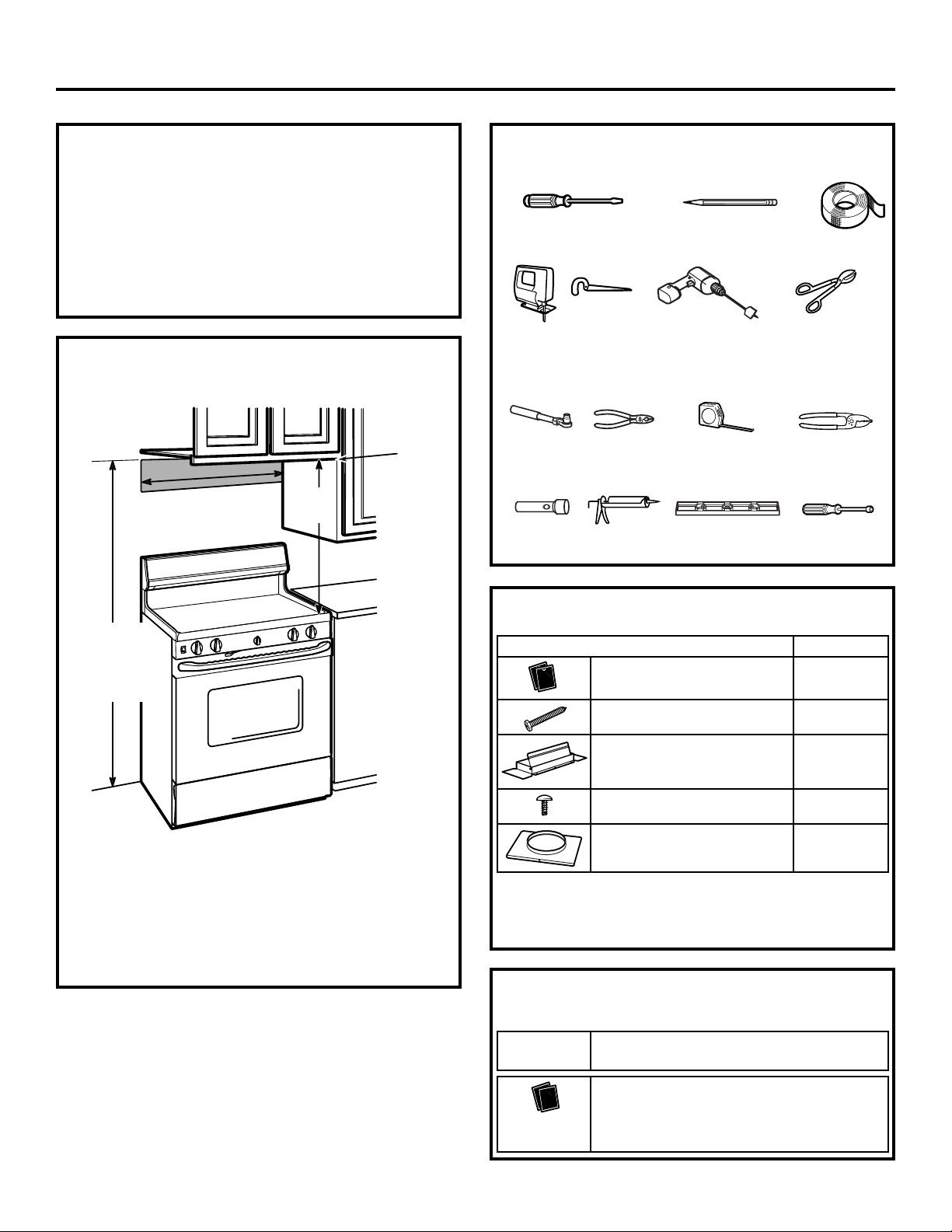
PART QUANTITY
Metal Grease Filters 2
Mounting Screws 4
Exhaust Adaptor 1
(for 31⁄4″ x 10″ rect. venting)
Exhaust Adaptor Screws 2
Exhaust Adaptor 1
(for 7” round venting)
9
• If the unit is damaged in shipment, return the unit to the
store in which it was bought for repair or replacement.
• If the unit is damaged by the customer, repair or
replacement is the responsibility of the customer.
• If the unit is damaged by the installer (if other than
the customer), repair or replacement must be made
by arrangement between customer and installer.
DAMAGE—SHIPMENT/INSTALLATION
PARTS INCLUDED
Some parts are shipped in the hood behind the filters.
On some models, the bottom cover of the hood also
needs to be removed to gain access to the parts.
MOUNTING SPACE
NOTES:
• This range hood is for installation over ranges up to
36″ wide.
• If you are going to vent your range hood to the
outside, see the “Ducting Requirements” section for
exhaust duct preparation.
66″ or more
from the floor
to the top of
the hood
30″ or 36″
30″
min.
Bottom edge of
cabinet needs
to be 30″ or
more from
the cooking
surface
Flat blade and Phillips
screwdrivers
Pencil
Metal snips
(in some
applications)
Electric drill
Saw (saber or keyhole)
Duct tape
Pliers
Level
Caulking
Tape measure
TOOLS YOU WILL NEED
1/4″ pivoting
hex socket
Flashlight
Wire stripper
1/4″ Nutdriver
Installation Instructions
Charcoal Filters—JV5 Series only, if recirculating
For 30″ hood models, order Kit no. WB02X10707.
For 36″ hood models, order Kit no. WB02X10708.
OPTIONAL ACCESSORIES
These kits can be ordered from your GE supplier.
Cord Kit—For both 30″ and 36″ models,
order Kit no. JXHC1.
Page 10
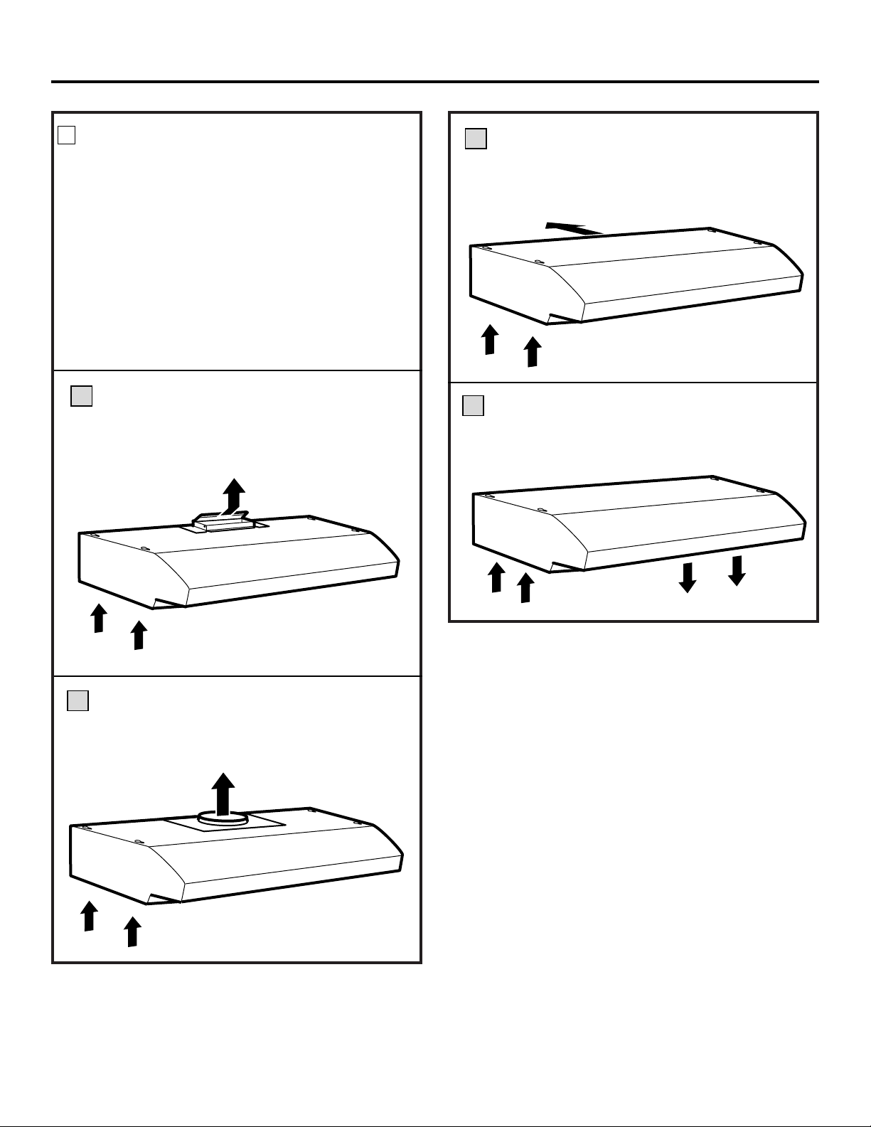
10
Outside top exhaust
(Vertical duct—3
1
⁄4″ x 10″ Rectangular)
Outside rear exhaust
(Horizontal duct—3
1
⁄4″ x 10″
Rectangular)
Outside top exhaust
(Vertical duct—7″ Round)
A
C
B
CHOOSE VENT OPTION
The outside vent exhaust option that your installation
requires will determine the hood knockouts that you
will use.
If the hood is to be installed in a recirculating, nonvented ductless manner, do not knock out any vent
openings in the hood. Only an electrical access hole
will be knocked out of the hood.
NOTE: Only JV5 Series models may be recirculated.
We do not recommend the recirculated configuration
for JV6 Series models.
Determine the vent option that your installation will
require from the following choices:
Recirculating
(Non-vented ductless—Optional for
JV5 Series models only)
D
1
Installation Instructions
Page 11
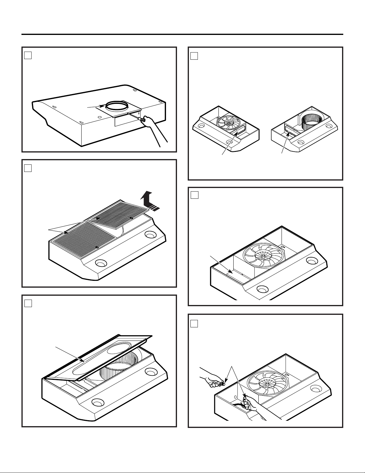
11
REMOVE EXHAUST ADAPTOR
Remove the 7″ round exhaust adaptor from the top of
the hood. Set it aside along with its mounting screws.
7″ round
exhaust
adaptor
REMOVE FILTERS
Remove the shipping tape holding the metal grease
filters in place. Pull down on the filter tabs and lift
the filters out. Set them aside.
REMOVE BOTTOM COVER
On models so equipped, remove the bottom cover
from the hood. Set the cover and its mounting
screws aside.
Bottom cover
(held in place
with 2
screws)
REMOVE OTHER EXHAUST ADAPTOR
Remove the 31⁄4″ x 10″ rectangular exhaust adaptor
from inside the hood. Set it aside along with its
mounting screws and parts bag. Depending on the
model, the exhaust adaptor will be located on the
left or right side.
31⁄4″ x 10″
rectangular
exhaust adaptor
3
1
⁄4″ x 10″
rectangular
exhaust adaptor
REMOVE WIRING COVER
On models so equipped, remove the wiring cover
from inside the hood. Set the cover and its mounting
screw aside.
Wiring
cover
REMOVE WIRING KNOCKOUT
Remove either the top or the back wiring knockout as
needed and install an approved strain relief clamp.
Strain relief
clamp
2
3
4
5
6
7
Filters
Installation Instructions
Page 12
Tie s
12
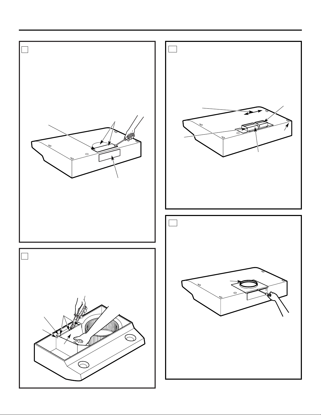
REMOVE DUCT KNOCKOUT(S)
If recirculating, non-vented ductless (optional for
JV5 Series models only), see note below and skip to
Step 12 D and proceed. We do not recommend the
recirculated configuration for JV6 Series models.
Using a flat blade screwdriver, remove the appropriate
duct knockout(s) from the top or back of the hood.
31⁄4″ x 10″ Rectangular
vertical discharge.
Remove top rectangular
duct knockout only.
7″ Round vertical
discharge. Remove semi-
circular duct knockout and top
rectangular duct knockout.
31⁄4″ x 10″ Rectangular
horizontal discharge. Remove
rear rectangular duct knockout only.
FOR HORIZONTAL DISCHARGE
INSTALLATIONS ONLY:
Remove the plate (on models so equipped) in front
of the horizontal discharge knockout. Cut the ties,
lift plate out and discard plate. DO NOT REMOVE
the metal strip held in place with two screws.
Metal strip
Plate
FOR 31⁄4″ X 10″ RECTANGULAR
DUCTED DISCHARGE
INSTALLATIONS ONLY:
Attach exhaust adaptor/damper over knockout
opening with two exhaust adaptor screws. Make sure
damper pivot is nearest to top/back edge of hood.
Remove tape from damper flap.
Up to 1″ side-to-
side adjustment
Tape
Top/back edge
Exhaust adaptor/damper
(vertical discharge position
shown)
Pivot
FOR 7″ ROUND VERTICAL
DUCTED DISCHARGE
INSTALLATIONS ONLY:
Re-install the 7″ round exhaust adaptor with its
screws, removed in Step 2 under the “Prepare the
Hood” section.
8
9
10
11
7″ round
exhaust
adaptor
NOTE: The 7″ round exhaust adaptor can be installed
up to 1 inch on either side of the hood center to
accommodate off-center ductwork. In extreme off-center
installations, one end of the duct connector may need
to be trimmed to clear the electrical cable clamp.
NOTE: The 7″ round damper is not included with
this product. It can be purchased as a kit by calling
800.626.2002. Order kit number JXDA23.
Installation Instructions
Screw
NOTE: The exhaust adaptor/damper can be installed
up to 1 inch on either side of the hood center to
accommodate off-center ductwork. In extreme offcenter installations, one end of the duct connector may
need to be trimmed to clear the electrical cable clamp.
NOTE: If the hood is to be installed in a recirculating,
non-vented ductless manner, order charcoal filters,
kit number WB02X10707 for 30″ hood models or
kit number WB02X10708 for 36″ hood models.
These kits can be ordered from your GE supplier.
Skip to Step 12 D and proceed.
Page 13
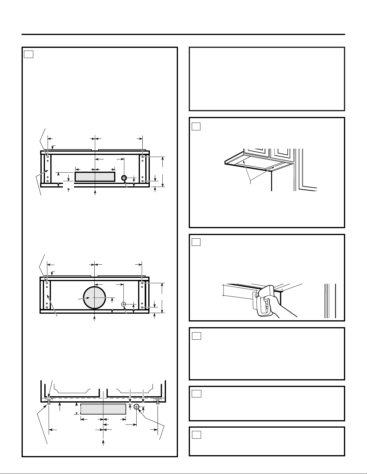
MARK HOLES
Select the vent option that your installation will
require and proceed to that section:
Hood mounting screws (4)
1315⁄16″ (30″ hood)
16
15
⁄16″ (36″ hood)
1315⁄16″(30″hood)
16
15
⁄16″(36″hood)
Cabinet front
Center
line
Electrical access hole
(in cabinet bottom)
Wood shims
(recessed-
bottom cabinets only)
Vertical duct
access hole
101⁄2″
1
1
⁄2″
2″
71⁄2″
5″
11⁄4″
A.
Outside top exhaust
(Vertical duct—3
1
⁄4″x 10″Rectangular)
• Use the diagram or the hood as a template and
mark the locations on the cabinet for ductwork,
electrical wiring and keyhole screw slots.
B.
Outside top exhaust (Vertical duct—7″ Round)
• Use the diagram or the hood as a template and
mark the locations on the cabinet for ductwork,
electrical wiring and keyhole screw slots.
Hood mounting screws (4)
1315⁄16″ (30″ hood)
1615⁄16″ (36″ hood)
1315⁄16″(30″hood)
1615⁄16″(36″hood
)
Cabinet front
Center
line
Electrical access
hole (in cabinet bottom)
Wood shims (recessed-
bottom cabinets only)
Access
hole for 7″
round duct
101⁄2″
1
1
⁄2″
2″
71⁄2″
5″
Cabinet
bottom
8″ DIA.
HOLE
CUT HOLES
Cut holes at marked locations for duct and electrical
wiring. For the vertical duct, cut out 3/4″ extra
toward the front of the cabinet so you can move the
duct freely when installing the hood. It may also ease
installation by cutting the hole 101⁄2″ instead of 10″.
FOR RECESSED-BOTTOM
CABINETS ONLY
RUN WIRES
Run the electrical wires through the wall or
cabinet according to National Electrical Code
and applicable local codes.
NOTE: DO NOT turn the power on until
installation is complete.
Cabinet Bottom
12
14
13
15
SCREW IN PARTWAY
Drive a mounting screw (from the hardware packet)
partway into each center of the narrow neck of the
keyhole slots marked on the cabinet bottom.
FEED IN WIRES
Lift the hood into position and feed the house
wiring through the wiring knockout.
16
17
Wood shims (recessed-bottom cabinets only)
Cabinet front
Center line
Electrical access hole
(in wall)
Hood mounting screws (4)
Horizontal duct
access hole
Cabinet
bottom
1315⁄16″ (30″ hood)
1615⁄16″ (36″ hood)
3
⁄4″
1
⁄8″
33⁄4″
51⁄4″
51⁄4″
71⁄2″
1315⁄16″ (30″ hood)
1615⁄16″ (36″ hood)
C.
Outside rear exhaust
(Horizontal duct—3
1
⁄
4
″
x 10″Rectangular)
• Use the diagram or the hood as a template and
mark the locations on the cabinet for ductwork,
electrical wiring and keyhole screw slots.
D.
Recirculating (non-vented ductless—
Available on JV5 Series models only)
• Use the hood as a template and mark the locations
on the cabinet for the electrical wiring and keyhole
screw slots.
• Since the hood is to be recirculated (not to be vented
outside), do not cut out any vent openings in the wall
or cabinet bottom.
Wood shims
• If the cabinets have front, side or back trim, make
2 wood shims the width of the trim and attach them
to the cabinet bottom recess on both sides. See Step
12 for marking locations.
51⁄4″
51⁄4″
Installation Instructions
13
Page 14
TROUBLESHOOTING CHECKLIST
If the hood seems to be operating at high speed when
the control is not set on high, or if ventilation seems
inadequate, check the following:
❏ Knockouts not removed from hood.
❏ Damper blade not opening.
❏ Reduced airflow because the duct is too small or
the duct length is too long.
❏ The duct is blocked.
❏ Undersized or restrictive wall or roof cap.
REPLACE WIRING COVER
On models so equipped, replace the wiring cover
or the bottom cover.
14
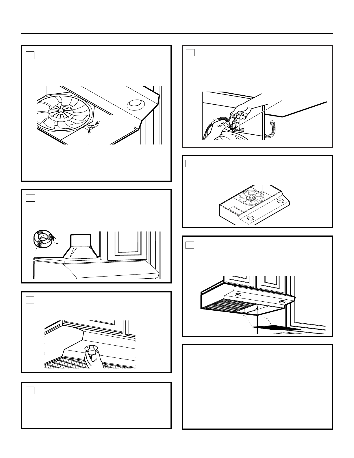
SECURE HOOD
Slide the hood back against the wall. Tighten
the mounting screws. Be sure the screw heads
are in the narrow neck of the keyhole slot.
Keyhole (4)
Mounting
screw (4)
NOTE: DO NOT PUSH ON FAN BLADE. Pushing
on the blade may cause it to interfere with other
hood parts.
FOLLOW ELECTRICAL CODE
Complete the electrical wiring according to
National Electrical Code and local codes.
NOTE: This hood must be permanently grounded.
Connect house wiring (120 VAC) to hood wiring.
CONNECT WIRING
Connect house black to hood black wire, house
white to hood white wire, and house ground under
green ground screw. Securely tighten the strain
relief clamp onto the house wiring.
Green ground screw
18
21
22
23
24
INSTALL LIGHT BULBS
Purchase and install two PAR20, 50 W maximum
halogen bulbs.
20
CONNECT DUCTWORK TO
HOOD
Use duct tape to make joints secure and air tight.
Duct tape
19
REPLACE FILTERS
Make sure fan blade turns freely. The installation is
complete. Turn on power at service panel, and test
for proper operation.
Installation Instructions
Page 15
15
GE Range Hood Warranty.
All warranty service provided by our Factory Service Centers
or an authorized Customer Care
®
technician. To schedule
service on-line, 24 hours a day, visit us at ge.com or call
800.GE.CARES (800.432.2737). Please have serial number
and model number available when calling for service.
For The Period Of: GE Will Replace:
One Year Any part of the range hood which fails due to a defect in materials or workmanship.
From the date of the During this limited one-year warranty, GE will also provide, free of charge, all labor and
original purchase in-home service to replace the defective part.
■ Service trips to your home to teach you how to use
the product.
■ Improper installation, delivery or maintenance.
■ Failure of the product if it is abused, misused,
or used for other than the intended purpose or
used commercially.
■ Replacement of house fuses or resetting of circuit
breakers.
■ Damage to the product caused by accident, fire, floods
or acts of God.
■ Incidental or consequential damage caused by possible
defects with this appliance.
■ Damage caused after delivery.
■ Product not accessible to provide required service.
What GE Will Not Cover:
This warranty is extended to the original purchaser and any succeeding owner for products purchased for home use
within the USA. If the product is located in an area where service by a GE Authorized Servicer is not available, you
may be responsible for a trip charge or you may be required to bring the product to an Authorized GE Service
Location for service. In Alaska, the warranty excludes the cost of shipping or service calls to your home.
Some states do not allow the exclusion or limitation of incidental or consequential damages. This warranty gives
you specific legal rights, and you may also have other rights which vary from state to state. To know what your
legal rights are, consult your local or state consumer affairs office or your state’s Attorney General.
Warrantor: General Electric Company. Louisville, KY 40225
Installation Instructions
Consumer Support
Safety Instructions Operating Instructions
EXCLUSION OF IMPLIED WARRANTIES—Your sole and exclusive remedy is product repair as provided
in this Limited Warranty. Any implied warranties, including the implied warranties of merchantability
or fitness for a particular purpose, are limited to one year or the shortest period allowed by law.
Page 16
Consumer Support.
GE Appliances Website
ge.com
Have a question or need assistance with your appliance? Try the GE Appliances Website 24 hours a day,
any day of the year! For greater convenience and faster service, you can now download Owner’s Manuals,
order parts, catalogs, or even schedule service on-line. You can also “Ask Our Team of Experts™”
your questions, and so much more...
Schedule Service ge.com
Expert GE repair service is only one step away from your door. Get on-line and schedule your service at
your convenience 24 hours any day of the year! Or call 800.GE.CARES (800.432.2737) during normal
business hours.
Real Life Design Studio ge.com
GE supports the Universal Design concept—products, services and environments that can be used by
people of all ages, sizes and capabilities. We recognize the need to design for a wide range of physical and
mental abilities and impairments. For details of GE’s Universal Design applications, including kitchen
design ideas for people with disabilities, check out our Website today. For the hearing impaired, please
call 800.TDD.GEAC (800.833.4322).
Extended Warranties ge.com
Purchase a GE extended warranty and learn about special discounts that are available while your warranty
is still in effect. You can purchase it on-line anytime, or call 800.626.2224 during normal business hours.
GE Consumer Home Services will still be there after your warranty expires.
Parts and Accessories ge.com
Individuals qualified to service their own appliances can have parts or accessories sent directly to their
homes (VISA, MasterCard and Discover cards are accepted). Order on-line today, 24 hours every day or
by phone at 800.626.2002 during normal business hours.
Instructions contained in this manual cover procedures to be performed by any user. Other servicing generally
should be referred to qualified service personnel. Caution must be exercised, since improper servicing may cause
unsafe operation.
Contact Us ge.com
If you are not satisfied with the service you receive from GE, contact us on our Website with all the details
including your phone number, or write to: General Manager, Customer Relations
GE Appliances, Appliance Park
Louisville, KY 40225
Register Your Appliance ge.com
Register your new appliance on-line—at your convenience! Timely product registration will allow for
enhanced communication and prompt service under the terms of your warranty, should the need arise.
You may also mail in the pre-printed registration card included in the packing material.
Printed in the United States
 Loading...