

Page 1

Use and Care & Installation Guide
30” Vented Range Hood
Model: JV376
Write Down the Model and Serial Numbers.
The Model and Serial Numbers are on a label on the
back wall of the hood and on the Consumer Product
Ownership Registration Card that came with your hood.
Before sending in this card, please write these numbers here:
Model Number
Serial Number
IMPOR TANT SAFETY INSTRUCTIONS
Read and save these instructions.
WARNING—TO REDUCE THE RISK OF FIRE,
ELECTRIC SHOCK, OR INJURYTO PERSONS,
OBSERVE THE FOLLOWING:
A. Use this unit only in the manner intended by the
manufacturer. If you have questions, contact the
manufacturer at the address or telephone number
listed in the warranty.
B. Before servicing or cleaning unit, switch power
off at service panel and lock service to prevent
power from being switched on accidentally. When
the service disconnecting means cannot be locked,
securely fasten a prominent warning device, such
as a tag, to the service panel.
C. Installation work and electrical wiring must be done by
qualified person(s) in accordance with all applicable
codes and standards, including fire-rated construction.
D. Sufficient air is needed for proper combustion and
exhausting of gases through the flue (chimney) of fuelburning equipment to prevent backdrafting. Follow the
heating equipment manufacturer’s guidelines and safety
standards such as those published by the National Fire
Protection Association (NFPA), and the American
Society for Heating, Refrigeration and Air Conditioning
Engineers (ASHRAE), and the local code authorities.
E. When cutting or drilling into wall or ceiling, do not
damage electrical wiring and other hidden utilities.
F. Ducted fans must always be vented to the outdoors.
G. To reduce the risk of fire, use only metal ductwork.
H. This unit must be grounded.
WARNING—TO REDUCE THE RISK OFA
RANGE TOPGREASE FIRE:
A. Keep fan, filters and grease-laden surfaces clean.
B. Always turn hood ON when cooking at high heat.
C. Don’t leave range unattended when cooking.
D. Use high settings on range only when necessary.
Heat oil slowly on low to medium setting.
E. Always use cookware and utensils appropriate for the
type and amount of food being prepared.
• When flaming foods under the hood, turn the fan on.
WARNING—TO REDUCE THE RISK OF INJURY
TO PERSONS IN THE EVENT OFARANGE TOP
GREASE FIRE, OBSERVE THE FOLLOWING:
A. SMOTHER FLAMES with a close-fitting lid, cookie
sheet, or metal tray, then turn off the burner. BE
CAREFUL TO PREVENT BURNS. If the flames do
not go out immediately, EVACUATE AND CALL
THE FIRE DEPARTMENT.
B. NEVER PICK UPA FLAMING PAN—You may be
burned.
C. DO NOT USE WATER, including wet dishcloths or
towels—a violent steam explosion will result.
D. Use an extinguisher ONLY if:
1. You know you have a Class ABC extinguisher,
and you already know how to operate it.
2. The fire is small and contained in the area where
it started.
3. The fire department is being called.
4. You can fight the fire with your back to an exit.
*Based on “Kitchen Firesafety Tips” published by NFPA.
CAUTION—For general ventilating use only. Do not use
to exhaust hazardous or explosive materials and vapors.
If You Need Service…
• Do not attempt to repair or replace any part of your
hood unless it is specifically recommended in this
guide. All other servicing should be referred to a
qualified technician.
SAVE THESE INSTRUCTIONS
GE Appliances
164D2966P166-2
Page 2

2
Venting
This hood must be vented ver tically through
upper cabinets or horizontally through an outside
wall. Ductwork is not included.
Improper duct sizing or restrictive roof caps
reduce air moving capacity and will not provide
enough ventilation for an indoor electric grill.
Indoor electric grills produce more smoke than
normal cooking and require at least 410 CFM to
provide adequate ventilation.
Follow the guidelines for proper duct sizing in the
ducting char ts.
NOTE: The venting system must
exhaust to the outside.
Cabinet Height
For most efficient operation, the top of the hood should
be approximately 66″ (167.6 cm) from the floor.
Tools Required:
• Drill; 11⁄4″ wood bit. • Pliers.
• Flat blade screwdriver. • Pencil, ruler and level.
• Saber saw or keyhole saw.
• Caulking, metal snips, duct tape, ducts (with
elbow and transition, if necessar y) and wall cap
or roof caps, as required.
INSTALLATION INSTRUCTIONS
Installing the Range Hood
Determine which direction the vent will be
installed (top or rear).
1. Remove filters and motor/light cover (3 screws).
2. Remove the blower motor by removing the
“packing screw” and the clip on the retainer bar.
Discard the clip and screw.
Unplug the motor from the junction box.
Snap the blower retainer
bar toward the rear of
the hood to release the
blower. Remove the
blower.
3. Remove the junction
box cover.
Remove the selected wiring knockout and duct
knockout from the top or rear of the hood. Use a
flat blade screwdriver to cut the tabs.
IMPORTANT: OBSERVE ALL GOVERNING
CODES AND ORDINANCES.
SAVE THESE INSTRUCTIONS FOR THE
LOCAL ELECTRICAL INSPECTOR’S USE.
WARNING: Disconnect power before servicing or cleaning the unit.
Blower Control Care of Filter Motor
The speed control can be adjusted
from OFF to high speed. At the
highest setting, the blower exhausts
410 CFM. It takes about 15 seconds
for the blower to reach high speed..
For most effective removal of smoke
and odors, turn the fan on at the
beginning of cooking and allow it to
run until smoke and odors are
removed from the room.
For greatest efficiency the aluminum
filter should be cleaned periodically.
To remove the filter, pull the tab to
the side and then down. Soak it in hot
water and detergent. Rinse and dry
thoroughly before replacing.
Lights Care of Exterior Surfaces
This hood has two lights. Do not use
bulbs larger than 75 watts. There are
two light levels. To change light
bulbs, first remove the filters. It is not
necessary to remove the blower cover.
Use a mild detergent to clean the hood.
DO NOT use abrasive cleansers.
Top Vent
Knockout
Snap
lock blower
retainer bar
When the control is not set on high
and if the motor seems to be
operating at high speed or if
ventilation seems inadequate, check
the following:
1. Knockouts not removed from hood.
2. Blower installed for vertical
discharge instead of horizontal
discharge or vice versa.
3. Damper blade not opening.
4. Reduced airflow because the duct is
too small or the length is too long.
5. The duct is blocked.
6. Undersized or restrictive wall or
roof cap.
Page 3
3
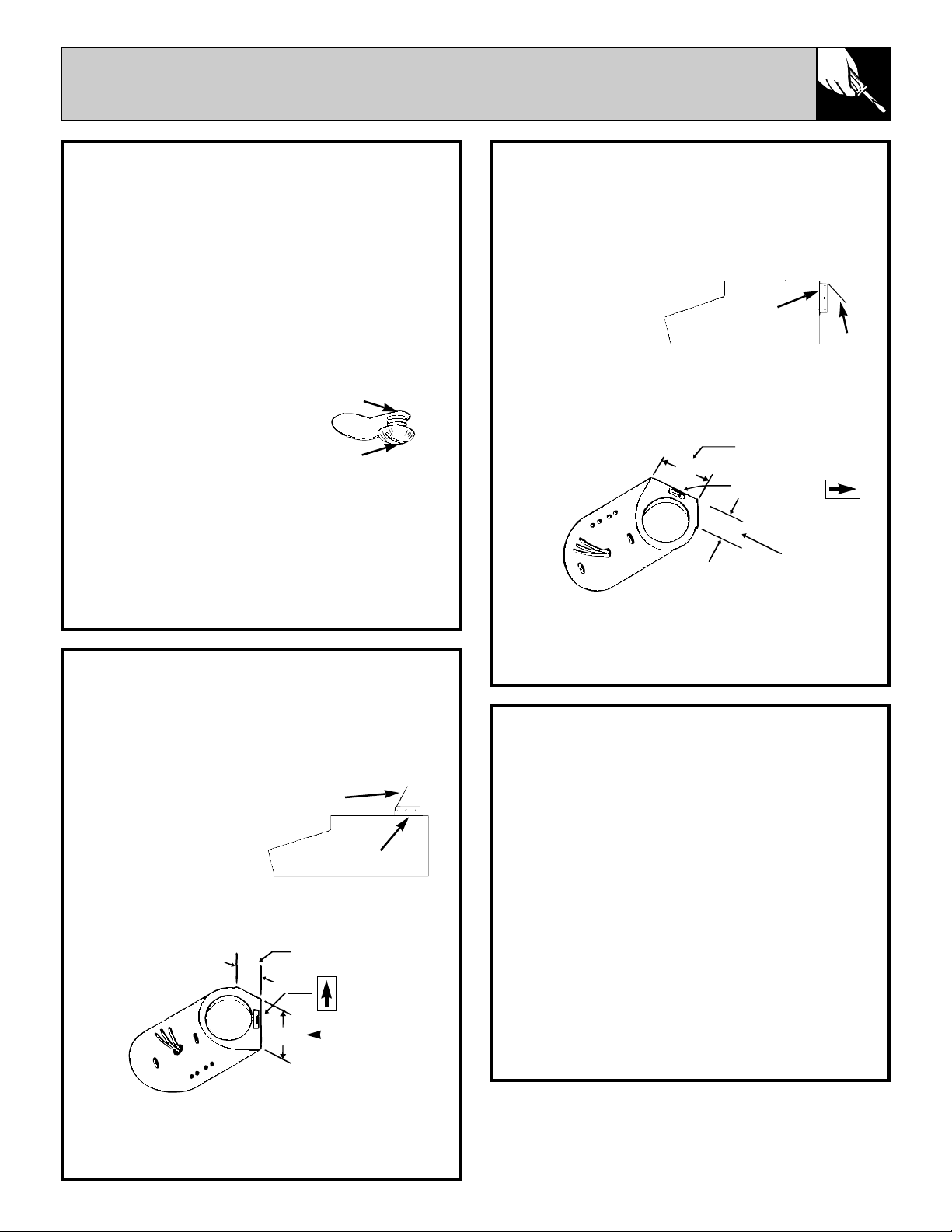
HORIZONTAL VENTING
(If the wall cap has a damper, do not install the
damper blade on the hood.)
Attach the damper with the small sheet metal
screws (#8 x 1/4″).
Check the damper
for free operation.
Open the damper
blade to
approximately 80
degrees.
Position the blower for horizontal discharge. The
air flow arrow on the blower should point to the
rear vent opening.
When the blower is in position, snap the blower
retainer bar toward the front into the indent.
Reattach the plug into the junction box.
8. Lift the hood into position and feed the house
wiring through the wiring knockout.
Slide the hood back against the wall.
Tighten the mounting screws. Be sure the screw
heads are in the narr ow neck of the keyhole slot.
9. Complete the electrical wiring in the wiring
box according to National Electrical Code and
local codes.
NOTE: This hood must be permanently
grounded.
10. Replace the junction box cover and blower
assembly.
Reattach the plug into the junction box.
Install light bulbs (not supplied with the hood).
Reattach bottom motor/light cover and filters.
11. Installation is complete. Tur n on the power.
VERTICAL VENTING
(If the roof cap has a damper, do not install the
damper blade on the hood.)
Attach the damper with the small sheet metal
screws (#8 x 1/4″).
Check the damper
for free operation.
Open the damper
blade to
approximately 80
degrees.
Position the blower for ver tical discharge. The
air flow arrow on the blower should point up
towards the vent opening.
When the blower is in position, snap the blower
retainer bar toward the front into the indent.
Reattach the plug into the junction box.
Blower discharge
Air flow arrow
This surface
to rear
3″
5″
Damper blade
to front
This surface to top
Blower
discharge
3″
5″
Air flow arrow
Damper
blade to top
Damper
4. Use the hood as a template. Mark the
locations on the cabinet or wall for ductwork,
electrical wiring and keyhole screw slots.
Cut holes at marked locations for duct and
electrical wiring. For the vertical duct, cut out 3/4″
extra toward the front of the cabinet for movement
of the duct when installing the hood.
5. Run the electrical wires through the wall or
cabinet according to National Electrical Code
and applicable local codes.
NOTE: DO NOT turn the power on until
installation is complete.
6. Drive the screw partway
into the center of the
narrow neck of the keyhole
slots marked on the
cabinets.
7. Follow the directions for ver tical or
horizontal venting.
NOTE: If the venting installation is NOT
correct, the blower will run at maximum RPM
regardless of the speed control setting.
When installing the blower housing, be
sure wires cannot contact the blower wheel.
Keyhole slot
in canopy
Screw
(supplied)
Damper
Page 4
INSTALLATION INSTRUCTIONS
Some states do not allow the exclusion or limitation of incidental or consequential damages, so the above limitation or exclusion
may not apply to you. This warranty gives you specific legal rights, and you may also have other rights which vary from state to state.
To know what your legal rights are in your state, consult your local or state consumer affairs office or your state’s Attorney General.
Warrantor: General Electric Company
If further help is needed concerning this warranty, write:
Manager—Customer Relations, GE Appliances, Louisville, KY 40225
Part No. 164D2966P166-2
Pub No. 49-8646-2
626778
12-98 CG
YOUR RANGE HOOD
WARRANTY
Staple sales slip or cancelled check
here. Proof of original purchase date
is needed to obtain service
under warranty.
JV376
Printed in the United States
WHAT IS NOT COVERED
• Service trips to your home to
teach you how to use the product.
Read your Use and Care material.
If you then have any questions about
operating the product, please contact
your dealer or our Customer
Relations office at the address
below, or call, toll free:
GE Answer Center
®
800.626.2000
consumer information service
• Improper installation.
If you have an installation problem,
contact your dealer or installer. You
are responsible for providing
adequate electrical, gas, exhausting
and other connecting facilities as
described in the Installation
Instructions provided with the
product.
• Replacement of the replaceable
filters.
• Replacement of house fuses or
resetting of circuit breakers.
• Failure of the product if it is used
for other than its intended
purpose or used commercially.
• Damage to product caused by
accident, fire, floods or acts of God.
WARRANTOR IS
NOT
RESPONSIBLE FOR
CONSEQUENTIAL DAMAGES.
WHAT IS COVERED
FULL ONE-YEAR WARRANTY
For one year from date of original
purchase, we will provide, free of
charge, parts and service labor in
your home to repair or replace
any
part of the hood
that fails because of
a manufacturing defect.
This warranty is extended to the original
purchaser and any succeeding owner
for products purchased for ordinary
home use in the 48 mainland states,
Hawaii and Washington, D.C. In
Alaska the warranty is the same
except that it is LIMITED because you
must pay to ship the product to the
service shop or for the service
technician’s travel costs to your home.
All warranty service will be
provided by our Factory Service
Centers or by our authorized
Customer Care®servicers during
normal working hours.
Should your appliance need
service, during warranty period
or beyond, call 800-GE-CARES
(800-432-2737).
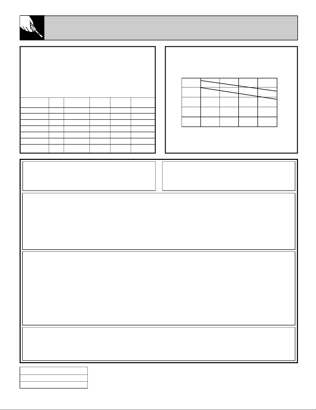
Ducting Chart
0
100
200
300
400
500
0 10 20 30 40 50
Air volume in CFM
Equivalent length in feet
Ductwork Requirements
Use 31⁄4x 10″ or 7″ round ducting for best performance.
The length of ductwork and number of elbows should
be kept to a minimum for ef ficient operation.
Use caulking to seal exterior openings around the hood.
Static Pressure vs Duct Length
Equivalent Duct Length (ft.)
Static Rect.
Pressure CFM 31⁄4x 10″ 7″ dia. 8″ dia. 9″ dia.
.06 4 10 19 34
.10 410 7 17 31 56
.15 400 11 25 47 83
.20 370 15 33 62 111
.25 345 18 42 78
90° elbow 5 11 12 14
45° elbow 2
1
⁄
2
51⁄
2
6 7
maximum recommended length
7″ RND
3
1
⁄4x 10″
3
1
⁄4x 10″ Transition to 7″ Round = 2 ft.
7″ Round elbow = 8 ft.
7″ Roof cap = 70 ft.
 Loading...