

Installation Instructions
27"& 30"ElectricBuilt-InWall Ovens
Questions? Call 1.800.GE.CARES (1.800.432.2737) or visitwww.GEAppliances.com
In Canada, call 1.800.561.3344 or visit www.GEAppliances.ca
BEFORE YOU BEGIN
Read these instructions completely and
carefully.
° IMPORTANT -- Savethese
instructions for local inspector's use.
° IMPORTANT -- Observe all
governing codes and ordinances.
• Note to Installer- Be sure to leave these
instructions with Consumer.
ATTENTION INSTALLER: All electric wall ovens must be hard-wired (direct-wired)
into an approved junction box. A plug and receptacle is NOT permitted on these products.
FOR YOUR SAFETY:
^,u,WARN ING: Before beginning the installation, switch power off at the service
panel and lock the service disconnecting means to prevent power from being switched on accidentally.
When the service disconnecting means cannot be locked, securely fasten a prominent warning device,
such as a tag, to the service panel.
Be sure the oven is securely installed in a cabinet that is firmly attached to the house structure.
Weight on the oven door could cause the oven to tip and result in injury. Never allow anyone to climb,
sit, stand or hang on the oven door.
Make sure the wall coverings, counters and cabinets around the oven can withstand the heat
(up to 200°F [93.3°C]) generated by the oven.
MATERIALS YOU MAY NEED
Junction Box
Wire Nuts
Strain Relief Clamp for 1/2" Conduit
36" (91 cm) of String
[_ REMOVE PACKAGING MATERIALS
Failure to remove packaging materials could result in damage to the appliance. Remove all
packing parts from oven, racks and heating elements. Remove protective film and labels on the
outer door and control panel. Also, remove plastic on trims and panel, all tape around the oven
and any shipping screws securing the oven to the base pad. Open oven door and remove
literature pack and oven racks. Remove the bottom trim from the top of the oven. It will be
installed at the end of the installation process. The trim is wrapped separately and taped
to the top of the unit.
• Note to Consumer- Keep these
instructions for future reference.
• Skill level - Installation of this appliance
requires a qualified installer or electrician.
• Proper installation is the responsibility
of the installer.
• Product failure due to improper installation
is not covered under Warranty.
TOOLS YOU MAY NEED
1/8" Drill Bit and Electric or Hand Drill
Phillips Screwdriver
Wire Strippers
DESIGN INFORMATION
SINGLE OVEN INSTALLATIONS
The single oven may be installed in a cabinet alone or above a warming drawer. The single oven may
also be installed below a countertop or below specified cooktops. See the label on top of the oven for
approved models.
DOUBLE OVEN INSTALLATIONS
A double oven may be installed in a cabinet alone or above a warming drawer. See the label on top of
the oven for approved models.
IMPORTANT: Always refer to individual installation instructions packed with each product for specific
requirements.
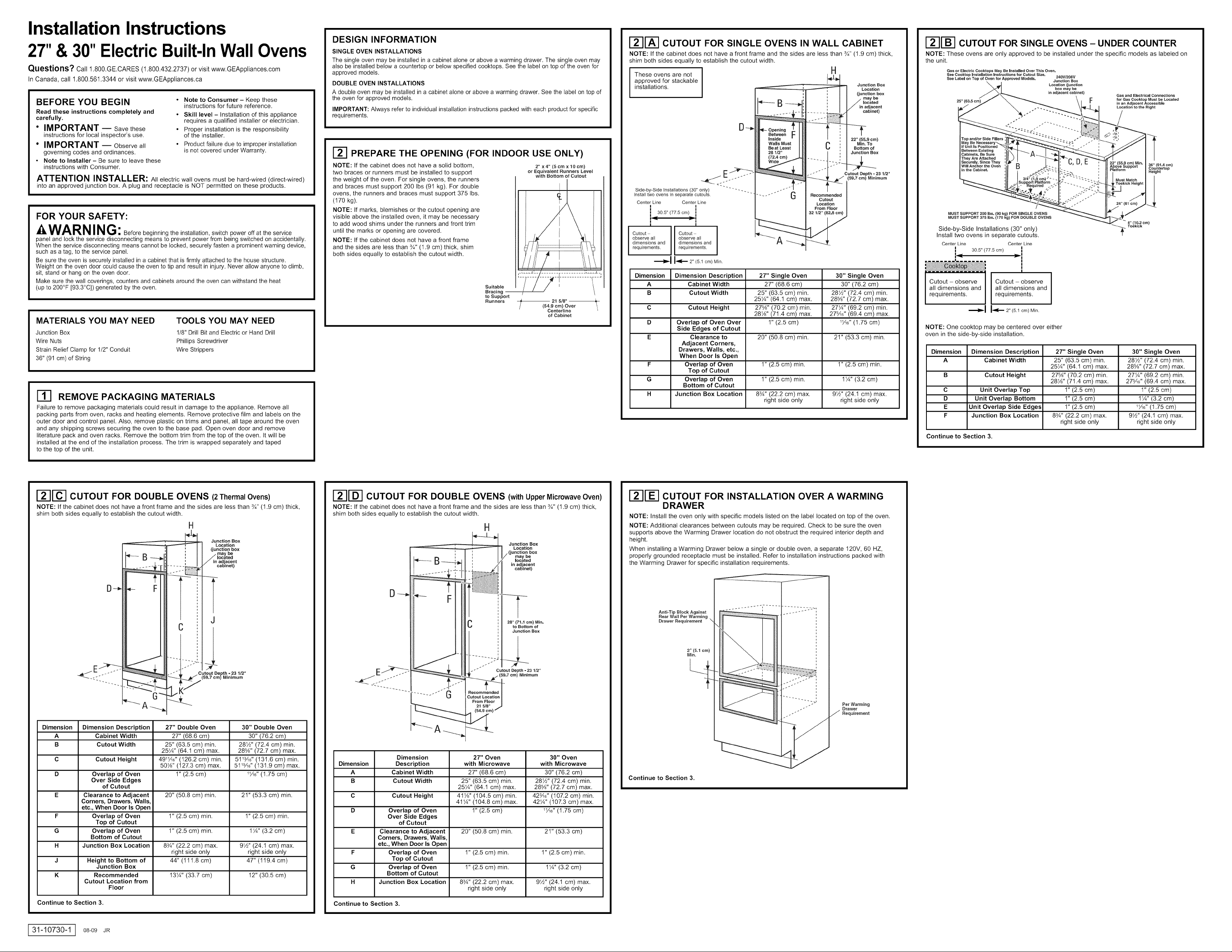
E_ PREPARE THE OPENING (FOR INDOOR USE ONLY)
NOTE: If the cabinet does not have a solid bottom,
two braces or runners must be installed to support
the weight of the oven. For single ovens, the runners
and braces must support 200 Ibs (91 kg). For double
ovens, the runners and braces must support 375 Ibs.
(170 kg).
NOTE: If marks, blemishes or the cutout opening are
visible above the installed oven, it may be necessary
to add wood shims under the runners and front trim
until the marks or opening are covered.
NOTE: If the cabinet does not have a front frame
and the sides are less than ¾" (1.9 cm) thick, shim
both sides equally to establish the cutout width.
Suitable
Bracing
to Support
Runners
2" x4"(5cmxtOcm)
or Equivalent Runners Level
with Bottom of Cutout
I 21 5/8"
(54.9 cm) Over /
Centerline
of Cabinet
r21rA-i CUTOUT FOR SINGLE OVENS IN WALL CABINET
NOTE: If the cabinet does not have a front frame and the sides are less than ¾" (1.9 cm) thick,
shim both sides equally to establish the cutout width.
These ovens are not I
approved for stackable
installations.
I
I
*--- B --.
Wails Must
Be at Least
28 1/2"
(72.4 cm)
Side-by-Side Installations (30" only) " - -- - - -.
Install two ovens in separate cutouts,
Center Line Center Line
I I
I 30.5" (77.5 cm) I
! !
I
observe all
dimensions and
Cutout
requirements,
I
observe all
dimensions and
Cutout 1
requirements,
I-4[,-- 2" (5,1 cm) Min,
Dimension Dimension Description 27" Single Oven 30" Single Oven
A Cabinet Width 27" (68.6 cm) 30" (76.2 cm)
B Cutout Width 25" (63.5 cm) min. 28½" (72.4 cm) min.
25¼" (64.1 cm) max. 28%" (72.7 cm) max.
C Cutout Height 27%" (70.2 cm) min. 27¼" (69.2 cm) min.
28½" (71.4 cm) max. 27%6" (69.4 cm) max.
D Overlap of Oven Over 1" (2.5 cm) _½6"(1.75 cm)
Side Edges of Cutout
E Clearance to 20" (50.8 cm) min. 21" (53.3 cm) min.
Adjacent Corners,
Drawers, Walls, etc.,
When Door Is Open
F Overlap of Oven 1" (2.5 cm) min. 1" (2.5 cm) min.
Top of Cutout
G Overlap of Oven 1" (2.5 cm) min. 1¼" (3.2 cm)
H Junction Box Location 8%" (22.2 cm) max. 9½" (24.1 cm) max.
Bottom of Cutout
right side only right side only
u
H
C Min. To
Recommended
Cutout
Location
From Floor
32 t12" (82.8 cm)
Junction Box
Location
(junction box
may be
located
in adjacent
cabinet)
22" (55.9 cm)
Bottom of
Junction Box
Cutout Depth - 23 t/2"
(59,7 cm) Minimum
12-11-B-ICUTOUTFORSINGLE OVENS-UNDER COUNTER
NOTE: These ovens are only approved to be installed under the specific models as labeled on
the unit.
Gas or Electric Cooktops May Be installed Over This Oven.
See Cooktop Installation instructions for Cutout Size, 240V/208V
See Label on Top of Oven for Approved Models, Junction Box
25" (63.5 cm)
MUST SUPPORT 200 Ibs. (90 kg) FOR SINGLE OVENS
MUST SUPPORT 375 Ibs, (170 kg) FOB DOUBLE OVENS
Side-by-Side Installations (30" only)
Install two ovens in separate cutouts.
Center Line Center Line
Cutout - observe
all dimensions and
requirements.
30.5" (77.5 cm) I
',_ _I
Cutout- observe I
all dimensions and
requirements.
'_1 I_ 2" (5,1 ore) Min,
I
I
I
NOTE: One cooktop may be centered over either
oven in the side-by-side installation.
Dimension Dimension Description 27" Single Oven 30" Single Oven
A Cabinet Width 25" (63.5 cm) min. 28½" (72.4 cm) rain.
B Cutout Height 27%" (70.2 cm) min. 27¼" (69.2 cm) min.
C Unit Overlap Top 1" (2.5 cm) 1" (2.5 cm)
D Unit Overlap Bottom 1" (2.5 cm) 1¼" (3.2 cm)
E Unit Overlap Side Edges 1" (2.5 cm) _6" (1.75 cm)
F Junction Box Location 8¾" (22.2 cm) max. 9½" (24.1 cm) max.
Continue to Section 3.
Location (junction
box may be
in adjacent cabinet)
I
Gas and Electrical Connections
for Gas Cooktop Must be Located
in an Ad acent Accessible
Locat on to the Right
22" (55.9 cm) Min. 36" (91.4 crn)
Above Support
Platform Countertop
Toeklck
4" (t0.2 cm)
Height
I
25¼" (64.1 cm) max. 28%" (72.7 cm) max.
28½" (71.4 cm) max. 27%6" (69.4 cm) max.
right side only right side only
_--]_"] CUTOUT FOR DOUBLE OVENS (2 ThermalOvens)
NOTE: If the cabinet does not have a front frame and the sides are less than ¾" (1.9 cm) thick,
shim both sides equally to establish the cutout width.
H
Junction Box
Location
(junction box
may be
located
J in adjacent
cal_inet)
--_
_- F
eli
G"
................A_ i _
E_[_] CUTOUT FOR DOUBLE OVENS (withUpperMicrowaveOven)
NOTE: If the cabinet does not have a front frame and the sides are less than ¾" (1.9 cm) thick,
shim both sides equally to establish the cutout width.
H
Junction BOX
Location
/ (junction box
/ may be
located
in adjacent
cabinet)
C 28" (71.1 cm) Min.
. -" Cutout Depth =23 1/2"
_.........__,_/(59.7 cm) Minimum
Cutout Location I
From Floor
to Bottom Of
_--][_ CUTOUT FOR INSTALLATION OVER A WARMING
DRAWER
NOTE: Install the oven only with specific models listed on the label located on top of the oven.
NOTE: Additional clearances between cutouts may be required. Check to be sure the oven
supports above the Warming Drawer location do not obstruct the required interior depth and
height.
When installing a Warming Drawer below a single or double oven, a separate 120V, 60 HZ,
properly grounded receptacle must be installed. Refer to installation instructions packed with
the Warming Drawer for specific installation requirements.
Anti-Tip Block Against
Rear Wall Per Warming
Drawer Requirement
2" (5.1 cm)
Min.
Per Warming
Drawer
Requirement
Dimension Dimension Description 27" Double Oven 30" Double Oven
A Cabinet Width 27" (68.6 cm) 30" (76.2 cm)
B Cutout Width 25" (63.5 cm) min. 28½" (72.4 cm) min.
25¼" (64.1 cm) max. 28%" (72.7 cm) max.
C Cutout Height 49_6 '' (126.2 cm) min. 51_%6'' (131.6 cm) min.
50½" (127.3 cm) max. 51_%6'' (131.9 cm) max.
D Overlap of Oven 1" (2.5 cm) _6" (1.75 cm)
Over Side Edges
of Cutout
E Clearance to Adjacent 20" (50.8 cm) min. 21" (53.3 cm) min.
Corners, Drawers, Walls,
etc., When Door Is Open
F Overlap of Oven 1" (2.5 cm) min. 1" (2.5 cm) min.
Top of Cutout
G Overlap of Oven 1" (2.5 cm) min. 1¼" (3.2 cm)
Bottom of Cutout
H Junction Box Location 8¾" (22.2 cm) max. 9½" (24.1 cm) max.
right side only right side only
J Height to Bottom of 44" (111.8 cm) 47" (119.4 cm)
K Recommended 13¼" (33.7 cm) 12" (30.5 cm)
Junction Box
Cutout Location from
Floor
Continue to Section 3.
31-10730-1 I 08-09 JR
A
Dimension Description with Microwave with Microwave
A Cabinet Width 27" (68.6 cm) 30" (76.2 cm)
B Cutout Width 25" (63.5 cm) min. 28½" (72.4 cm) min.
C Cutout Height 41½" (104.5 cm) min. 42%6" (107.2 cm) min.
D Overlap of Oven 1" (2.5 cm) _6" (1.75 cm)
E Clearance to Adjacent 20" (50.8 cm) min. 21" (53.3 cm)
F Overlap of Oven 1" (2.5 cm) min. 1" (2.5 cm) min.
G Overlap of Oven 1" (2.5 cm) min. 1¼" (3.2 cm)
H Junction Box Location 8¾" (22.2 cm) max. 9½" (24.1 cm) max.
Continue to Section 3.
Dimension 27" Oven 30" Oven
25¼" (64.1 cm) max. 28%" (72.7 cm) max.
41¼" (104.8 cm) max. 42¼" (107.3 cm) max.
Over Side Edges
of Cutout
Corners, Drawers, Walls,
etc., When Door Is Open
Top of Cutout
Bottom of Cutout
right side only right side only
Continue to Section 3.
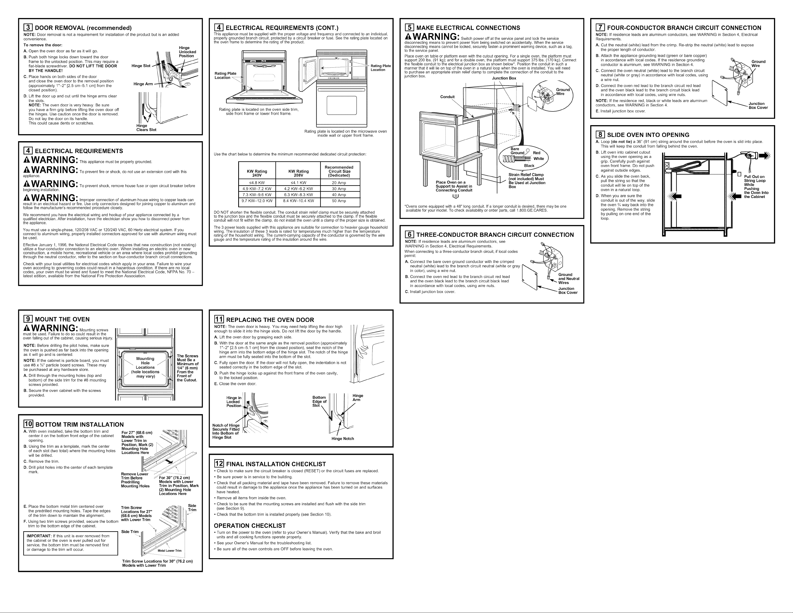
r_ DOOR REMOVAL (recommended)
NOTE: Door removal is not a requirement for installation of the product but is an added
convenience.
To remove the door:
A. Open the oven door as far as it will go.
B. Push both hinge locks down toward the door
frame to the unlocked position. This may require a
flat-blade screwdriver. DO NOT LIFT THE DOOR
BY THE HANDLE!
C. Place hands on both sides of the door
and close the oven door to the removal position
(approximately 1"-2" [2.5 cm-5.1 cm] from the
closed position).
D. Lift the door up and out until the hinge arms clear
the slots.
NOTE: The oven door is very heavy. Be sure
you have a firm grip before lifting the oven door off
the hinges. Use caution once the door is removed.
Do not lay the door on its handle.
This could cause dents or scratches.
II I_ Unlocked
/_ /_ Position
Hinge Slot 1_ ,,
Hinge Arm __b._
Hinge
Clears Slot
Hinge
ELECTRICAL REQUIREMENTS
_4,WARN ING:This appliance must be properly grounded.
-4,WARN ING: To prevent fire or shock, do not use an extension cord with this
appliance.
_4,WARN ING: To prevent shock, remove house fuse or open circuit breaker before
beginning installation.
_a,WARN ING:Improper connection of aluminum house wiring to copper leads can
result in an electrical hazard or fire. Use only connectors designed for joining copper to aluminum and
follow the manufacturer's recommended procedure closely.
We recommend you have the electrical wiring and hookup of your appliance connected by a
qualified electrician. After installation, have the electrician show you how to disconnect power from
the appliance.
You must use a single-phase, 120/208 VAC or 1201240 VAC, 60 Hertz electrical system. If you
connect to aluminum wiring, properly installed connectors approved for use with aluminum wiring must
be used.
Effective January 1, 1996, the National Electrical Code requires that new construction (not existing)
utilize a four-conductor connection to an electric oven. When installing an electric oven in new
construction, a mobile home, recreational vehicle or an area where local codes prohibit grounding
through the neutral conductor, refer to the section on four-conductor branch circuit connections.
Check with your local utilities for electrical codes which apply in your area. Failure to wire your
oven according to governing codes could result in a hazardous condition. If there are no local
codes, your oven must be wired and fused to meet the National Electrical Code, NFPA No. 70 -
latest edition, available from the National Fire Protection Association.
ELECTRICAL REQUIREMENTS (CONT.)
This appliance must be supplied with the proper voltage and frequency and connected to an individual,
properly grounded branch circuit, protected by a circuit breaker or fuse. See the rating plate located on
the oven frame to determine the rating of the product.
Rating Plate
Rating Plate
Location
Rating plate is located on the oven side trim,
side front frame or lower front frame.
)late is located on the microwave oven
Rating
inside wall or upper front frame.
Use the chart below to determine the minimum recommended dedicated circuit protection:
KW Rating KW Rating Circuit Size
240V 208V (Dedicated)
<4.8 KW <4.1 KW 20 Amp
4.9 KW-7.2 KW 4.2 KW-6.2 KW 30 Amp
7.3 KW-9.6 KW 6.3 KW-8.3 KW 40 Amp
9.7 KW-12.0 KW 8.4 KW-10.4 KW 50 Amp
DO NOT shorten the flexible conduit. The conduit strain relief clamp must be securely attached
to the junction box and the flexible conduit must be securely attached to the clamp. If the flexible
conduit will not fit within the clamp, do not install the oven until a clamp of the proper size is obtained.
The 3 power leads supplied with this appliance are suitable for connection to heavier gauge household
wiring. The insulation of these 3 leads is rated for temperatures much higher than the temperature
rating of the household wiring. The current-carrying capacity of the conductor is governed by the wire
gauge and the temperature rating of the insulation around the wire.
Recommended
Location
)
r_ MAKE ELECTRICAL CONNECTIONS
_4,WARN ING: Switch power off at the service panel and lock the service
disconnecting means to prevent power from being switched on accidentally. When the service
disconnecting means cannot be locked, securely fasten a prominent warning device, such as a tag,
to the service panel.
Place oven on table or platform even with the cutout opening. For a single oven, the platform must
support 200 Ibs. (91 kg); and for a double oven, the platform must support 375 Ibs. (170 kg). Connect
the flexible conduit to the electrical junction box as shown below*. Position the conduit in such a
manner that it will lie on top of the oven in a natural loop when the oven is installed. You will need
to purchase an appropriate strain relief clamp to complete the connection of the conduit to the
junction box. Junction Box
Conduit
Strain Relief Clamp
Place Oven on a
Support to Assist in
Connecting Conduit
*Ovens come equipped with a 48" long conduit. If a longer conduit is desired, there may be one
available for your model. To check availability or order parts, call 1.800.GE.CARES.
[_ THREE-CONDUCTOR BRANCH CIRCUIT CONNECTION
NOTE: If residence leads are aluminum conductors, see
WARNING in Section 4, Electrical Requirements.
When connecting to a three-conductor branch circuit, if local codes
permit:
A. Connect the bare oven ground conductor with the crimped
neutral (white) lead to the branch circuit neutral (white or gray
in color), using a wire nut.
B. Connect the oven red lead to the branch circuit red lead
and the oven black lead to the branch circuit black lead
in accordance with local codes, using wire nuts.
C. Install junction box cover.
(not included) Must
Be Used at Junction
Box
ound
d Neutral
res
unction
Box Cover
17-1 FOUR-CONDUCTOR BRANCH CIRCUIT CONNECTION
NOTE: If residence leads are aluminum conductors, see WARNING in Section 4, Electrical
Requirements.
A. Cut the neutral (white) lead from the crimp. Re-strip the neutral (white) lead to expose
the proper length of conductor.
B. Attach the appliance grounding lead (green or bare copper)
in accordance with local codes. If the residence grounding
conductor is aluminum, see WARNING in Section 4.
C. Connect the oven neutral (white) lead to the branch circuit
neutral (white or gray) in accordance with local codes, using
a wire nut.
D. Connect the oven red lead to the branch circuit red lead
and the oven black lead to the branch circuit black lead
in accordance with local codes, using wire nuts.
NOTE: If the residence red, black or white leads are aluminum
conductors, see WARNING in Section 4.
E. Install junction box cover.
Ground
Junction
Box Cover
_-_ SLIDE OVEN INTO OPENING
A. Loop (do not tie) a 36" (91 cm) string around the conduit before the oven is slid into place.
This will keep the conduit from falling behind the oven.
B. Lift oven into cabinet cutout
using the oven opening as a
grip. Carefully push against
oven front frame. Do not push
against outside edges.
C. As you slide the oven back,
pull the string so that the
conduit will lie on top of the
oven in a natural loop.
D. When you are sure the
conduit is out of the way, slide
the oven ¾ way back into the
opening. Remove the string
by pulling on one end of the
loop.
Pull Out on
String Loop
While
Pushing
the Oven Into
the Cabinet
r-_ MOUNT THE OVEN
WARN ING: Mountingscrews
must be used. Failure to do so could result in the
oven falling out of the cabinet, causing serious injury.
NOTE: Before drilling the pilot holes, make sure
the oven is pushed as far back into the opening
as it will go and is centered.
NOTE: If the cabinet is particle board, you must
use #8 x ¾" particle board screws. These may
be purchased at any hardware store.
A. Drill through the mounting holes (top and
bottom) of the side trim for the #8 mounting
screws provided.
B. Secure the oven cabinet with the screws
provided.
BOTTOM TRIM INSTALLATION
A. With oven installed, take the bottom trim and For 27" (68.6 cm)
center it on the bottom front edge of the cabinet Models with
opening. Lower Trim in
B. Using the trim as a template, mark the center Position, Mark (2)
of each slot (two total) where the mounting holes Locations Here
will be drilled.
C. Remove the trim.
D. Drill pilot holes into the center of each template
mark.
Trim Before _ For 30" (76.2 cm)
E. Place the bottom metal trim centered over
the predrilled mounting holes. Tape the edges
of the trim down to maintain the alignment.
F. Using two trim screws provided, secure the bottom
trim to the bottom edge of the cabinet.
IMPORTANT: If this unit is ever removed from
the cabinet or the oven is ever pulled out for
service, the bottom trim must be removed first
or damage to the trim will occur.
Trim Screw _._:I_._ I, Side
with Lower Trim
Mounting
Hole
Locations
(hole locations
may vary)
Mounting Hole
Remove Lower /
Predrilling Models with Lower
Mounting Holes Trim in Position, Mark
Locations for 27" <'._y_ u Trim
(68.6 cm) Models _,! _ _ "
Side Trim IHI _
Trim Screw Locations for 30" (76.2 cm)
Models with Lower Trim
%,
The Screws
Must Be a
Minimum of
1/4" (6 mm)
From the
Front of
the Cutout.
(2) Mounting Hole
Locations Here
:i
etal Lower Tdm
.......................... I
I1"11REPLACING THE OVEN DOOR
NOTE: The oven door is heavy. You may need help lifting the door high
enough to slide it into the hinge slots. Do not lift the door by the handle.
A. Lift the oven door by grasping each side.
B. With the door at the same angle as the removal position (approximately
1"-2" [2.5 cm-5.1 cm] from the closed position), seat the notch of the
hinge arm into the bottom edge of the hinge slot. The notch of the hinge
arm must be fully seated into the bottom of the slot.
C. Fully open the door. If the door will not fully open, the indentation is not
seated correctly in the bottom edge of the slot.
D. Push the hinge locks up against the front frame of the oven cavity,
to the locked position.
E. Close the oven door.
Hinge in
Locked II m !_:&
Edge of }1 il
slot i i
Positio_
Notch of Hing'_e _'_"_._
Securely Fitted I[_\_ .. "_.\_
Into Bottom of........... "
Hinge Slot
r_ FINAL INSTALLATION CHECKLIST
• Check to make sure the circuit breaker is closed (RESET) or the circuit fuses are replaced.
• Be sure power is in service to the building.
• Check that all packing material and tape have been removed. Failure to remove these materials
could result in damage to the appliance once the appliance has been turned on and surfaces
have heated.
• Remove all items from inside the oven.
• Check to be sure that the mounting screws are installed and flush with the side trim
(see Section 9).
• Check that the bottom trim is installed properly (see Section 10).
OPERATION CHECKLIST
• Turn on the power to the oven (refer to your Owner's Manual). Verify that the bake and broil
units and all cooking functions operate properly.
• See your Owner's Manual for the troubleshooting list.
• Be sure all of the oven controls are OFF before leaving the oven.
Bottom i rmilli Hinge
Hinge Notch

Instrucciones de instalacibn
H0rn0sdeparedel ctric0semp0trad0sde27"y30"
_Preguntas? Llame al 1.800.GE.CARES (1.800.432.2737) o visite GEAppliances.com
En Canad& Ilame al 1.800.561.3344 o visite www.GEAppliances.ca.
ANTES DE COMENZAR
Lea estas instrucciones per complete y con
detenimiento.
• IMPORTANTE -- Guardeestas
instruccionespara el use de inspectoreslocales.
• IMPORTANT -- Cumplacontodoslos
cOdigosy ordenanzas vigentes.
• Nota al instalador-AsegQrese de dejar estas
instruccionescon el Consumidor.
ATENCl0NINSTALADOR:Todoslosh0rnosdeparedebctric0sdebenc0ntarconcableadodec0nexi6npermanente
(cableadodirect0)dentr0deunacajadec0nexi0nesapr0bada.Enest0spr0duct0sNOsepermitelac0nexbndeltip0"enchufeyreceptacuto".
PARA SU SEGURIDAD:
-4,ADVE RTE NCIA:Antes de comenzar la instalaciOn,desconecte la energia
del panel de servicio y bloquee los medios de desconexiOn para evitar el accionamiento de laenergia de
manera accidental. Cuando los medios de desconexiOn de servicio no pueden bloquearse, coloque sobre
el panel de servicio un dispositivo de advertencia bien visible, come una etiqueta.
El horno debe instalarse bien en un gabinete que se encuentre firmemente sujeto ala estructura de la casa.
Si se coloca peso sobre la puerta del homo, _ste puede volcarse y provocar lesiones. Nunca permita que
nadie se suba, siente, pare o cuelgue de la puerta del horno.
Verifique que el revestimiento de las paredes, mostradores y gabinetes ubicados alrededor del horno puedan
soportar el calor (hasta 200°F [93,3°C]) generado per el homo.
MATERIALES QUE PUEDE NECESITAR
Caja de conexiones
Taponesde alambre
Abrazadera de aliviodetensionpara conductode 1/2"
36" (91 cm) de hilo
[_ QUITE LOS MATERIALES DE EMPAQUE
No quitar los mater!ales de empaque puede provocar dafios al electrodomestico. Quite todas las partes
de empaque del homo, bandejas y elementos de calentamiento. Quite la pelicula protectora y las
etiquetas de la puerta exterior y panel de control. Tambien, quite los elementos plasticos de los
rebordes y panel, toda la cinta que cubre el horno y los torn!lies de envio que fijan el homo ala
almohadilla base. Abra la puerta del horno y quite el material informative y las bandejas del horno.
Quite el reborde inferior de la parte superior del homo. Se colocara al final del proceso de instalacion.
El reborde se encuentra envuelto en forma separada y adherido en la parte superior de la unidad.
•Nota al consumidor- Conserve estas
instrucciones para referencia futura.
• Nivel de destreza - La instalaciOn de este
aparato requiere un instalador o electricista
calificados.
• El instalador tiene la responsabilidad de
efectuar una instalaciOn adecuada.
• La garantia no cubre las fallas del producto
provocadas per una instalaciOn incorrecta.
HERRAMIENTAS NECESARIAS
Broca de perforadora de 1/8" y perforadora
el_ctrica o de mane
Destornillador de estrella
Alicates pelacables
INFORMACION DE DISENO
INSTALACIONES DE HORNO UNICO
El homo 0nice puede instalarse solo en un gabinete o sobre un caj6n calentador. El homo 0nice
tambi_n puede instalarse debajo de un mostrador de encimera o debajo de las estufas especificadas.
Vea la etiqueta de la parte superior del homo pare consulter los modelos aprobados.
INSTALACIONES DE HORNO DOBLE
Puede instalarse un homo doble solo en un gabinete o sobre un caj6n calentador. Vea la etiqueta de
la parte superior del homo pare consulter los modelos aprobados.
IMPORTANTE: Siempre consulte las instrucciones de instalaciones individuales enviadas con cada
producto para requerimientos especificos.
r_ PREPARE LA ABERTURA (SOLO PARA use EN EL INTERIOR)
NOTA: Si el gabinete no cuenta con un fondo Guiasde2"x 4" (5 emx 10cm)
sOlido, deben instalarse dos abrazaderas 0 guias oequivalentesa nivel con
para soportar el peso del homo. Para hornos
On!cos, las guias o abrazaderas deben soportar
200 Ibs (91 kgs). Para hornos dobbs, las guias
o abrazaderas deben soportar 375 Ibs (170 kgs).
NOTA: Si marcas, imperfecciones o la abertura
resultaran visibles sobre el homo instalado, puede
ser necesario agregar cutlas de madera bajo las
guias y el reborde frontal hasta cubrir las marcas
o la abertura.
NOTA: Si el gabinete no cuenta con un armazOn
frontal y los lades son menores a un grosor de ¾"
(1,9 cm), coloque cutlas uniformemente sobre
ambos lades para establecer al ancho de la
abertura.
Abrazaderas
adecuadas --
pare sostener
las guies 21 5/8" (54,9 cm)
el rondo del recorte
bre |a linea central \
del gabinete
r_r_ ABERTURAPAPAHORNOSUNICOSENUNGABIENTEDE PARED
NOTA: Si el gabinete no cuenta con un armazon frontal y los lades son menores a un grosor de 3/4"
(1,9 cm), coloque cutlas uniformemente sobre ambos lades para establecer al ancho de la abertura.
Estos hornos no estan I
aprobados para
instalaciones apilables.
Instalaciones lade a lade (s61o 30") " " " - - - - - -...
Instale dos hornos en aberturas separadas.
Linea central Linea central
1 1
I 3&5" (77,5 cm) I
I
I
cumpJa con todas
las dimensiones
Abertura
y requerimientos.
cumpla con todas
las dimensiones
Abertu ra - l
y requerimientos.
l'_'_ 2" (5,1 cm) min.
DimensiOn Descdpcionde la dimension Horno unico de 27" Horno unico de 30"
A Ancho del gabinete 27" (68,6 cm) 30" (76,2 cm)
B Ancho de la abertura 25" (63,5 cm) rain. 28½" (72,4 cm) min.
C Altura de la abertura 27%" (70,2 cm) min. 27¼" (69,2 cm) rain.
D Superposici6n del homo 1" (2,5 cm) _½6"(1,75 cm)
sobre los costados
laterales de la abertura
E Espacio respecto 20" (50,8 cm) min. 21" (53,3 cm) min.
de esquinas adyacentes,
cajones, paredes, etc.,
F Superposicibn de la 1" (2,5 cm) min. 1" (2,5 cm) min.
parte superior del horno
G Superposicibn de la 1" (2,5 cm) min. 1¼" (3,2 cm)
parte inferior del horno
H Ubicaci6n de la caja 8¾" (22,2 cm) max. 9½" (24,1 cm) max.
I
-i
I
g_
_entre las
paredes F
internas
debe ser
de perle
G
!
C
Ubicacibn
recomendada
de !a aberture
desde el piso
UbieaeiOn de !e
caja de cortex!ones
(la caja de conexiones
puede hailarse en un
gabinete adyacente)
----__+_
22" (55,9 cm)
rain. haste la
parte inferior
de la eaja
de conexiones
Prefundidad de !a
(59,7 cm) rain!me
25¼" (64,1 cm) max. 28%" (72,7 cm) max.
28W' (71,4 cm) max. 27%6" (69,4 cm) max.
cuando la puerta
esta abierta
de la abertura
de la abertura
de conexiones sOlo lade derecho sOlo lade derecho
1/2"
_-_ _ ABERTURAPARAHORNOS0NICOS-BAJ0ELMOSTRADORDEENCIMERA
NOTA: Estos hornos sOlo pueden instalarse bajo los modelos especificos come se indica en la
etiqueta de la unidad.
Instale dos hornos en aberturas separadas.
Abertura - cumpla
con todas las
dimensiones y
requerimientos.
NOTA: Una estufa puede centrarse sobre cualquier
homo en la instalaciOn de lade a lade.
DimensiOn Descdpcionde la dimension Horno unico de 27" Horno unico de 30"
Contim]e en la secci6n 3.
Pueden instalarse estufas a gas o eldctrieas sobre este homo,
Vet las instrucciones de instalaci6n de la estufa pare el
tamafie de la abertura,
Vet la etiqueta de la parte superior del homo pare Ubicaci6n de la caja
modelos aprobados, de cortex!ones de
25" (63,5 cm) F
DEBE PODER SOSTENER 200 LBS. (90 kg) PARA HORNOS t)NICOS
DEBE PODER SOSTENER 375 LBS. (170 kg) PARA HORNOS DOBLES
Instalaciones lade a lade (s01o 30")
Linea central Linea central
30,5" (77,5 cm) I
246V/208V
(la caja de cortex!ones
puede hallarse en un
gabinete adyacente)
Las cortex!ones de gas
y el_ctricas pare estufas
a gas deben ubicarse en
una ubicacibn adyacente
accesible sobre la derecha,
sobre la plataforrna AItura del mostrador
36" (91,4 cm)
de encimera
Place de protecci6n
',_ _I
I
I
I
Abertura - cumpla
con todas las
dimensiones y
requerimientos.
'_}_I _ 2" (5,1 cm) Min.
A Ancho del gabinete 25" (63,5 cm) min. 28½" (72,4 cm) min.
B Altura de la abertura 27%" (70,2 cm) min. 27¼" (69,2 cm) rain.
C Superposici6n de la 1" (2,5 cm) 1" (2,5 cm)
unidad en parte superim
D Superposici6n de la 1" (2,5 cm) 1¼" (3,2 cm)
unidad en parte inferior
E Superposici6n de la 1" (2,5 cm) 11_6"(1,75 cm)
F Ubicaci6n de la caja 8¾" (22,2 cm) max. 9½" (24,1 cm) max.
unidad en costados laterales
de conexiones sOlo lade derecho sOlo lade derecho
25¼" (64,1 cm) max. 28%" (72,7 cm) max.
28W' (71,4 cm) max. 27%6" (69,4 cm) max.
r_[_ ABERTURA PARA HORNOS DOBLES (2 homes term!cos)
NOTA: Si el gabinete no cuenta con un armazon frontal y los lades son menores a un grosor de 3/4"
(1,9 cm), coloque cutlas uniformemente sobre ambos lades para establecer al ancho de la abertura.
H
Ubicecibn de !a
caja de conexioees
(!a caja de conexiones
ju puede hallarse en
n gabinete adyacente)
g --II,
",_ F
C i J
G"
_-................A_ i _
DimensiOn Descripcion de la dimension Horno doble de 27" Horno doble de 30"
A Ancho del gabinete 27" (68,6 cm) 30" (76,2 cm)
B Ancho de la abertura 25" (63,5 cm) min. 28½" (72,4 cm) min.
C Altura de la abertura 49_6 '' (126,2 cm) min. 51_%6'' (131,6 cm) min.
D Superposici6n del homo 1" (2,5 cm) _A6" (1,75 cm)
sobre los costados
laterales de la abertura
E Espacio respecto de 20" (50,8 cm) min. 21" (53,3 cm) min.
esquinasadyacentes,cajones,
paredes, etc., cuando
la puerta esta abierta
F Superposicion de la parte 1" (2,5 cm) min. 1" (2,5 cm) min.
superior del homo
de la abertura
G Superposicion de la parte 1" (2,5 cm) min. 1¼" (3,2 cm)
H Ubicacion de la caja 8¾" (22,2 cm) max. 9½" (24,1 cm) max.
inferiordel homo de laabertura
de conexiones sOlo lade derecho sOlo lade derecho
J Altura hasta la parte inferior 44" (111,8 cm) 47" (119,4 cm)
de la caja de conexiones
K Ubicacion recomendada 13¼" (33,7 cm) 12" (30,5 cm)
de la abertura desde el piso
25¼" (64,1 cm) max. 28%" (72,7 cm) max.
50W' (127,3 cm) max. 51_%6'' (131,9 cm) max.
[_[_ ABERTURAPARAHORNOSDOBLES(conhomo demicroondassuperior)
NOTA: Si el gabinete no cuenta con un armazOn frontal y los lades son menores a un grosor de 3/4"
(1,9 cm), coloque cutlas uniformemente sobre ambos lades para establecer al ancho de la abertura.
H
Ubicaci6n de ia caja
de conexiones
_ y puedeha arseen
C
. -" Profundidad de
" !a abertura - 23 f/2"
Ubicaci6n
recornendada
de la abertura
(la caja de conexiones
un gabinete adyacente)
28" (71,1 crn) rain.
haste !a parte inferior
de la caja de conexiones
.._9,7 cm) minimo
._1pise
A
DimensiOn de la dimension con microondas con microondas
A Ancho del gabinete 27" (68,6 cm) 30" (76,2 cm)
B Ancho de la abertura 25" (63,5 cm) min. 28½" (72,4 cm) min.
C Altura de la abertura 41W' (104,5 cm) min. 42¾6" (107,2 cm) min.
D Superposici6n del horno 1" (2,5 cm) 11_6"(1,75 cm)
E Espacio respecto de 20" (50,8 cm) rain. 21" (53,3 cm)
F Superposicibn de la parte 1" (2,5 cm) rain. 1" (2,5 cm) rain.
G Superposici6n de la parte 1" (2,5 cm) rain. 1¼" (3,2 cm)
H Ubicaci6n de la caja 8¾" (22,2 cm) max. 9½" (24,1 cm) max.
Descripci6n Horno de 27" Horno de 30"
25¼" (64,1 cm) max. 28%" (72,7 cm) max.
41¼" (104,8 cm) max. 42¼" (107,3 cm) max.
sobre los costados
laterales de la abertura
esquinas adyacentes, cajones,
paredes, etc., cuando
la puerta esta abierta
superior del homo
de la abertura
inferior del homo
de la abertura
de conexiones sOlo lade derecho sOlo lade derecho
1-211-E-IABERTURA PARA INSTALACION SOBRE UN CAJON
CALENTADOR
NOTA: Instale el homo s61ocon los modelos especificos listados en la etiqueta ubicada
en la parte superior del homo,
NOTA: Pueden necesitarse espacios adicionaJes entre las aberturas, Verifique que los soportes
del homo sobre la ubicaci6n de caj6n calentador no obstruyan la profundidad y altura interiores
requeridas,
Cuando instaJe un caj6n caJentador debajo de un homo _lnico o doble, debe instaJarse
un tomacorriente separado de 120V, 60 HZ con adecuada conexi6n a tierra, Consulte
las instrucciones de instalacion enviadas con el cajon calentador para requisites especificos
de instalaciOn.
Bloque anti-voicaduras
contra la pared trasera
seg_n requisite del
caj6n ealentador
2" (5,1 cm)
rain.
Seg_3n !os requisites
de! caj6n caientador
Continue en la seccibn 3.
Contim]e en la secci6n 3.
31-10730-1 ] 08-09 JR
Contim]e en la secci6n 3.

_] REMOCION DE LA PUERTA (recomendada)
NOTA: La remocion de la puerta no es un requerimiento de la instalaci6n del producto,
pero es una comodidad adicional.
Para quitar la puerta:
A. Abra la puerta del homo en su totalidad.
B. Presione ambas trabas de la bisagra hacia abajo
en direccidn del marco de la puerta hasta
destrabarlas. Para esto puede hacer falta un
destornillador de lados pianos, iNO LEMANTE
LA PUERTA DE LA MANIJA!
C. Coloque las manos sobre ambos lados y cierre
la puerta del horno hasta la posici6n de remoci6n
(aproximadamente 1"-2" [2,5 cm-5,1 cm]
de la posici6n de cierre).
D. Levante la puerta hasta que los brazos
de la bisagra hayan salido de las ranuras.
NOTA: La puerta del homo es muy pesada.
AsegQrese de tener un agarre firme antes de
levantar la puerta del homo de sus bisagras.
Tenga cuidado una vez que haya quitado la
puerta. No deposite la puerta sobre la manija.
Esto puede provocar abolladuras o rayones.
La bisagra sale
de la ranura
Posicibn
REQUlSITOS ELC:CTRICOS (CONT.)
Este aparato debe recibir el voltaje y frecuencia adecuados, y debe conectarse a un circuito derivado
individual con adecuada conexi6n a tierra, protegido por un interruptor de circuitos o fusible. Ver la
placa de clasificaci6n ubicada en el armaz6n del horno para determinar la clasificaci6n del producto.
=
Ubicaci6n
de la placa
de clasificaci6n
Ubicaci6n
La placa de clasificaci6n se encuentra en el
reborde lateral del horno, armaz6n frontal lateral
o armaz6n frontal inferior.
La placa de clasificacion se encuentra en el
horno de microondas dentro de la pared interior
o en el armazdn frontal superior.
r_ REALICE LAS CONEXIONES ELC:CTRICAS
--a, ADVERTENCIA: Desconecte la energia del panel de servicio y bloquee
los medios de desconexi6n para evitar el accionamiento de la energia de manera accidental. Cuando
los medios de desconexi6n de servicio no pueden bloquearse, coloque sobre el panel de servicio un
dispositivo de advertencia bien visible, como una etiqueta.
Coloque el horno sobre una mesa o plataforma en forma nivelada con la abertura. Para un horno
Onico, la plataforma debe soportar 200 Ibs. (91 kg); para un horno doble, la plataforma debe soportar
375 Ibs. (170 kg). Conecte el conducto flexible a la caja de conexiones el6ctrica como se indica
abajo*. Coloque el conducto de modo que quede sobre el horno con un lazo natural cuando el horno
se instale. Tendr_ que comprar una abrazadera para alivio de tensi6n apropiada para completar
la conexi6n del conducto a la caja de conexiones.
Conducto
Caja de conexiones
CONEXION DE CIRCUITO DERIVADO DE CUATRO
CONDUCTORES
NOTA: Si los cables domesticos son conductores de aluminio, ver la ADVERTENCIA
de la seccidn 4, Requisitos electricos.
A. Corte el cable neutral (blanco) del conector de engarce.
Pele el cable neutral (blanco) para exponer la Iongitud
correcta del conductor.
B. Conecte el cable a tierra del artefacto (verde o cobre)
de acuerdo con los codigos locales. Si el conductor a tierra
de la residencia es de aluminio, ver ADVERTENCIA
de la secci6n 4.
C. Conecte el cable neutral (blanco) del horno con el neutral
de circuito derivado (blanco o gris) de acuerdo con c6digos
locales, utilizando un tap6n de alambre.
D. Conecte el cable rojo del horno al cable rojo del circuito
derivado y el cable negro del horno al cable negro del circuito
derivado de acuerdo con los c6digos locales, utilizando
tapones de alambre.
NOTA: Si los cables rojos, negros o blancos son conductores de aluminio, ver ADVERTENCIA
de la secci6n 4.
E. Ilnstale la tapa de la caja de conexiones.
Cable a
rra
Tapa de la
caja de
conexiones
REQUISITOS ELC:CTRICOS
ADVE RTE NCIA: Este aparato debe contar con una adecuada conexi6n
a tierra.
ADVE RTE NCIA: Para prevenir un incendio o descarga el_ctrica, no utilice
un cable de extensi6n con este aparato.
ADVE RTENCIA: Para prevenir una descarga el_ctrica, quite el fusible o
abra el interruptor de circuitos antes de comenzar la instalaci6n.
-4,ADVE RTENCIA: Una conexi6n inadecuada de cableado dom6stico de
aluminio con cables de cobre puede generar un peligro el6ctrico o un incendio. S61o use conectores
disefiados para unir cobre con aluminio y siga al pie de la letra el procedimiento recomendado del
fabricante.
Recomendamos que un electricista calificado conecte el cableado el6ctrico de su aparato. Despu6s
de la instalaci6n, solicite al electricista que le indique c6mo desconectar la energia del aparato.
Usted debe usar un sistema el_ctrico de fase Qnica de 120/208 VAC o 120/240 VAC de 60 hercios.
Si tiene una conexi6n con cableado de aluminio, deben utilizarse conectores adecuadamente
instalados para utilizar con cableado de aluminio.
Vigente desde el 1 de enero de 1996, el C6digo El_ctrico Nacional requiere que las nuevas
construcciones (no existentes) utilicen una conexi6n de cuatro conductores a un homo el_ctrico.
Cuando instale un homo el_ctrico en una construcci6n nueva, una casa rodante, un vehiculo
recreativo o un _rea donde los c6digos locales prohiben la conexi6n a tierra a trav6s de un conductor
neutral, consulte la secci6n sobre conexiones en circuito derivado de cuatro conductores.
Consulte alas empresas de servicio pQblico sobre los c6digos el6ctricos que se aplican en su area.
No realizar el cableado de su homo de acuerdo con los c6digos vigentes puede provocar una
situaci6n peligrosa. Si no existen c6digos locales, el cableado y fusibles de su homo deben cumplir
con el C6digo El_ctrico Nacional, NFPA No 70, Qltima edici6n, disponible en National Fire Protection
Association (Asociaci6n Nacional de Protecci6n contra Incendios).
Utilice la tabla de abajo para determinar la protecci6n de circuito dedicado minima recomendada:
Clasificacibn Tamaho de circuito
de KW Clasificacibn de KW recomendado
240V 208V (dedicado)
<4,8 KW <4,1 KW 20 Amp
4,9 KW-7,2 KW 4,2 KW-6,2 KW 30 Amp
7,3 KW-9,6 KW 6,3 KW-8,3 KW 40 Amp
9,7 KW-12,0 KW 8,4 KW-10,4 KW 50 Amp
NO acorte el conducto flexible. La abrazadera del alivio de tensi6n del conducto debe estar bien sujeta
a la caja de conexiones y el conducto flexible debe estar bien sujeto a la abrazadera. Si el conducto
flexible no entra dentro de la abrazadera, no instale el homo hasta obtener una abrazadera del
tamafio adecuado.
Los 3 cables de energia suministrados con este aparato son adecuados para conexiones con
cableados dom6sticos de calibre mayores. La aislaci6n de estos 3 cables esta clasificada a
temperaturas mucho mas elevadas que la clasificaci6n del cableado dom6stico. La capacidad
de transmitir corriente del conductor esta determinada por el calibre del cable y la clasificaci6n
de temperatura de la aislaci6n alrededor del cable.
La abrazadera del alivio
Coloque el homo
en un soporte para
ayudar a la conexibn
del conducto
*Loshornos vienen equipadoscon unconducto de48" de Iongitud.Sidesea unconducto mAslargo, puede haber
uno disponiblepara su modelo.Para verificarla disponibilidado solicitar piezas,Ilameal 1.800.GE.CARES.
de tensibn (no incluido)
debe usarse en la caja
de conexiones
_-_ CONEXION DE CIRCUITO DERIVADO DE TRES CONDUCTORES
NOTA: Si los cables domesticos son conductores de aluminio,
ver la ADVERTENCIA de la seccidn 4, Requisitos electricos.
Cuando conecte un circuito derivado de tres conductores,
si Io permiten los c6digos locales:
A. Conecte el conductor a tierra del horno con el cable neutral
(blanco) en rizo al neutral del circuito derivado (blanco o gris)
utilizando un tapdn de alambre.
B. Conecte el cable rojo del horno al cable rojo del circuito derivado
y el cable negro del horno al cable negro del circuito derivado de
acuerdo con los cddigos locales, utilizando tapones de alambre.
C. Instale la tapa de la caja de conexiones.
_ _ tierra y
L "'_ neutrales
"-.J _ Tapa de
hies a
la caja de
conexiones
E_ DESLICE EL HORNO DENTRO DE LA ABERTURA
A. Enrosque (no ate) un hilo de 36" (91 cm) alrededor del conducto antes de deslizar el horno
en su lugar. Esto no permitira que el conducto caiga detras del horno.
B. Levante el horno dentro
de la abertura del gabinete
utilizando el horno abierto
como agarre. Con cuidado
empuje contra el armazdn
frontal del horno. No presione
sobre los bordes externos.
C. A medida que desliza el horno
hacia arras, jale del hilo para
que el conducto quede sobre
el horno con un lazo natural.
D. Cuando se asegure de que
el conducto no este en el
camino, deslice el horno
3/4 hacia atras dentro de la
abertura. Quite el hilo jalando
de un extremo del lazo.
Jale del lazo
de hilo
mientras
empuja el
homo dentro
del gabinete
_-_ INSTALE EL HORNO
-4,ADVERTENCIA:
Deben utilizarse tornillos de montaje. Si no Io hace,
el horno puede caer del gabinete, Io que provocaria
una lesi6n grave.
NOTA: Antes de perforar los orificios piloto,
asegt]rese de que el horno se encuentre
en la posicidn final de la abertura y centrado.
NOTA: Si el gabinete es de placa de particulas,
deben utilizarse tornillos #8 x ¾" para dicho
material. Estos pueden adquirirse en cualquier
ferreted&
A. Perfore a traves de los orificios de montaje
(superiores e inferiores) del reborde lateral
para los tornillos de montaje #8 provistos.
B. Asegure el gabinete del horno con los tornillos
provistos.
_] INSTALACI(3N DEL REBORDE INFERIOR
A. Con el horno instalado, quite el reborde inferior
y centrelo sobre el borde inferior frontal de la
abertura del gabinete.
B. Utilizando el reborde como una plantilla, marque
el centro de cada ranura (dos en total) donde
se perforaran los orificios de montaje.
C. Quite el reborde.
D. Perfore orificios piloto en el centro de cada marca
de la plantilla.
E. Coloque el reborde inferior metalico centrado
sobre los orificios de montaje pre-perforados.
Coloque cinta adhesiva en los bordes del reborde
para conservar la alineaci6n.
F. Utilizando los dos tornillos provistos, asegure
el reborde inferior al lado inferior del gabinete.
IMPORTANTE: Siesta unidad alguna vez
se quita del gabinete o si el horno se quita de
servicio, el reborde inferior debe quitarse antes
o el reborde sufrira dafios.
Ubicaciones
de montaje
(las ubicaciones
pueden variar)
Para modelos
de 27" (68,6 cm)
con el reborde
inferior en
posicibn, marque
(2) ubicaciones
para orificios
de montaje aqui
Quite el reborde
inferior antes de
pre-perforar los
orificios de
montaje
Ubicaciones aqui
de tornillos del _.._1 Reborde
reborde para _ _ lateral
(68,6cm)con F
modelos de 27" _
Reborde _ /_
lateral. III _
'_
Ubicaciones de los tornillos del reborde
para 30" (76,2 cm)
Modelos con reborde inferior
Los
tornillos
deben
hallarse a
un minimo
de %"
(6 mm)
desde el
frente de
laabertura.
modelos de
30" (76,2 cm) con
el reborde inferior
en posicibn, marque
(2) ubicaciones para
orificios de montaje
eborde inferior metalico
................ ....... I
Illl COMO VOLVER A COLOCAR LA PUERTA DEL HORNO
NOTA: La puerta del horno es pesada. Puede necesitar ayuda para
levantar la puerta Io suficiente como para deslizarla dentro de las ranuras
de la bisagra. No levante la puerta de la manija.
A. Levante la puerta del horno tomandola de ambos lados.
B. Con la puerta en el mismo angulo de la posicion de remoci6n
(aproximadamente 1"-2" [2,5 cm-5,1 cm] desde la posici6n de
cerrado), introduzca la muesca del brazo de la bisagra dentro del
extremo inferior de la ranura de la bisagra. La ranura del brazo de
la bisagra debe estar bien colocada en la parte inferior de la ranura.
C. Abra la puerta por completo. Si la puerta no se abre por completo,
la muesca no esta bien colocada en el extremo inferior de la ranura.
D. Presione las trabas de la bisagra hacia arriba contra el armazon frontal
de la cavidad del horno, hasta alcanzar la posici6n de trabado.
E. Cierre la puerta del horno.
i Brazo
la posicion I1_ /_ _ de la ranura
de trabado_
,sa.raenII .a.oinferior
bisagra bien Ik_. \.._
colocada en la Ir_\ -\ -_ -\
parte inferior de
la ranura de la
bisagra
IIZI LISTA DE CONTROL FINAL DE LA INSTALACI()N
• Verifique que el interruptor de circuitos se encuentre cerrado (RESET) o que los fusibles
del circuito se hayan reemplazado.
• Asegt]rese de que haya suministro electrico en el edificio.
• Controle que se haya quitado todo el material de empaque y la cinta adhesiva. No quitar estos
materiales puede provocar dafios al electrodomestico una vez que el aparato se haya
encendido y las superficies se hayan calentado.
• Quite todos los elementos ubicados dentro del horno.
• Asegt]rese de que los tornillos de montaje se encuentren instalados y nivelados con el reborde
lateral (ver secci6n 9).
• Verifique que el reborde inferior este bien instalado (ver secci6n 10).
LISTA DE CONTROL DE FUNCIONAMIENTO
• Accione la energia del horno (consulte el Manual del propietario). Verifique que las unidades
de horneado y asado y que todas las funciones de coccidn operen bien.
• Ver el Manual del propietario para la lista de deteccidn y soluci6n de problemas.
• Asegt]rese de que todos los controles del horno se encuentren en OFF (apagado) antes
de dejar el horno.
i ilidi la bisagra
Ranura de la bisagra
 Loading...