

Page 1

GE Consumer Products
TECHNICAL SERVICE GUIDE
2003 Slide-In, Single and Double Wall
Ovens with TrivectionTM Cooking
MODEL SERIES:
JS998
JT930
JT980
ZET3038
ZET3058
PUB # 31-9115 3/04
Page 2

IMPORTANT SAFETY NOTICE
The information in this service guide is intended for use by
individuals possessing adequate backgrounds of electrical,
electronic, and mechanical experience. Any attempt to repair a
major appliance may result in personal injury and property
damage. The manufacturer or seller cannot be responsible for the
interpretation of this information, nor can it assume any liability in
connection with its use.
WARNING
To avoid personal injury, disconnect power before servicing this
product. If electrical power is required for diagnosis or test
purposes, disconnect the power immediately after performing the
necessary checks.
RECONNECT ALL GROUNDING DEVICES
If grounding wires, screws, straps, clips, nuts, or washers used to
complete a path to ground are removed for service, they must be
returned to their original position and properly fastened.
PRECAUTIONS TO AVOID POSSIBLE EXPOSURE TO
EXCESSIVE MICROWAVE ENERGY
A. Do not attempt to operate this oven with the door open since
open-door operation can result in harmful exposure to microwave
energy . It is important not to tamper with the safety interlocks.
B. Do not place any object between the oven front face and the door
or allow soil or cleaner residue to accumulate on sealing surfaces.
C. Do not operate the oven if it is damaged. It is particularly important
that the oven door close properly and that there is no damage to
the:
• Door (bent)
• Hinges and latches (broken or loosened)
• Door seals and sealing surfaces
D. The oven should not be adjusted or repaired by anyone except
properly qualified service personnel.
GE Consumer Products
Technical Service Guide
Copyright © 2003
All rights reserved. This service guide may not be reproduced in whole or in part
in any form without written permission from the General Electric Company .
– 2 –
Page 3

Table of Contents
Basics of Element Cycling ..............................................................................................33
Component Locator Views ..............................................................................................12
Components Requiring Oven Removal...........................................................................15
Control Boards Connector Locator..................................................................................28
Control Features................................................................................................................8
Control Panel (
Control Panel Insert (Slide-In Range).................................................................................25
Cooktop (Slide-In Range) ...................................................................................................25
Current Limit Board (
Diagnostics and Service Information ...............................................................................32
Door Switches ................................................................................................................. 24
Failure Codes ..................................................................................................................32
Glass T ouch Assembly (
High Limit Thermal One-Shot TCO .................................................................................23
HVT Cooling Fan (
Introduction ........................................................................................................................4
Left and Right Thermal TCO's (
Left Cooling Fan (
Lower Cooling Fan (Double Wall Oven Only).............................................................................20
Lower Oven Bake and Clean Thermal TCO's (
Magnetron Capacitor and Diode ......................................................................................27
Magnetron Cooling Fan and Thermal TCO (
Microwave Components ..................................................................................................26
Microwave Fuse...............................................................................................................27
Microwave Leakage Test..................................................................................................39
Nomenclature ....................................................................................................................7
Operational Notes ............................................................................................................10
Oven Components ..........................................................................................................15
Oven Light Bulb Assembly...............................................................................................17
Oven Temperature Sensor (
Oven Vent Fan.................................................................................................................2 1
Right Cooling Fan ............................................................................................................20
Sail Switches (
Schematics and Wiring Diagrams ...................................................................................70
Self-Clean Latch Motor ....................................................................................................23
Service Mode ...................................................................................................................34
Stirrer Motor .....................................................................................................................27
Trivection
Trivection
TrivectionTM Door Assembly .............................................................................................16
Trivection
Troubleshooting ...............................................................................................................40
Troubleshooting Cooking Loads in Service Mode ............................................................35
TM
Convection Fan Assembly............................................................................19
TM
Convection Fan Motor...................................................................................19
TM
Bake, Broil and Convection Elements..........................................................18
Double and Single Wall Ovens) ....................................................................25
Slide-In Range) .................................................................................29
Slide-In Range) ............................................................................25
Double and Single Wall Ovens) ...............................................................27
Slide-In Range).................................................................22
Slide-In Range).......................................................................................26
Double Wall Ovens)...................................... 22
Wall Ovens) ..................................................26
RTD) .....................................................................................20
Double and Single Wall Ovens).....................................................................21
– 3 –
Page 4
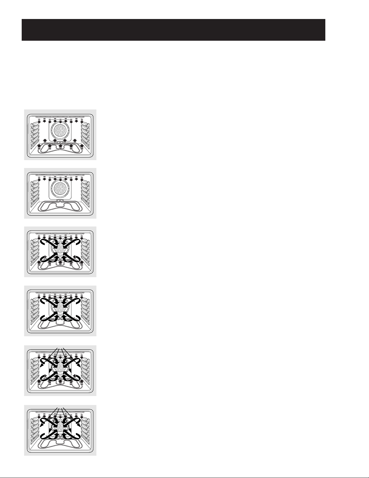
Bake
Baking is cooking with heated air. The
upper and lower elements cycle back and
forth to heat the air and maintain
temperature. Used for traditional baking
and roasting. Best for delicate items.
Broil
Heat is provided by the upper element
to broil your food. May be used with the
oven door open or closed.
Convection Bake—Multi and Single Rack
Heat is provided by the element in the
back of the oven, along with the upper
and lower elements. The air is circulated
with a reversing fan system. The fan will
change directions to provide optimal
evenness and browning. The Multi Rack
option is ideal for evenly baking foods
when using more than one rack. The
1 Rack option, used for one rack of food,
cooks food faster than BAKE mode.
Convection Roast
Heat is provided by the upper element
and circulated with the reversing fan
system. The fan will change directions to
provide optimal evenness and browning.
Good for roasting large tender cuts of
meat or poultry, uncovered. Roasts foods
up to 25% faster.
Speed Bake
Heat is provided by the three elements
and microwave. The exact combination
of elements is automatically determined
by the food category selected. Air is
circulated with the reversing fan system
described above. Ideal for baking and
roasting foods up to five times faster.
Speed Broil
Heat is provided by the upper element
and microwave. Air is circulated with the
reversing fan system described above.
Oven door must be closed. Ideal for
broiling foods to medium to well done
doneness levels two times faster than
traditional broil.
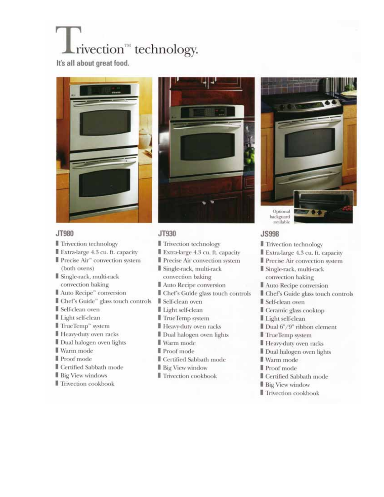
Introduction
The GE Profile oven with Trivection™ technology is a microwave-assist wall oven designed to cook food
up to five times faster than a traditional oven. This oven gives the user the flexibility to cook food in
traditional cooking modes (bake or broil), convection modes (convection bake and convection roast) or
in speedcook modes (speed bake and speed broil). This oven features easy-to-use controls that will
guide you through oven operations.
– 4 –
Page 5
– 5 –
Page 6
– 6 –
Page 7
Model Number
Nomenclature
J T 9 8 0 B H 1 B B
GE Cooking Product
J = GE
ZE = Monogram Electric
Configuration
S = 30-in. Slide-In Oven
T = 30-in. Wall Oven
Feature Pack
Designates features–the higher
the number, the more features.
Nomenclature
Product Color
CC = Bisque WW = White
BB = Black
SS = Stainless Steel
Indicator for Engineering and
Product Service Only
Model Year Designator
Glass Color
C = Bisque W = White
B = Black
S = Stainless Steel
Serial Number
The first two numbers of the serial number
identify the month and year of manufacture.
Example: AF123456S = January, 2003
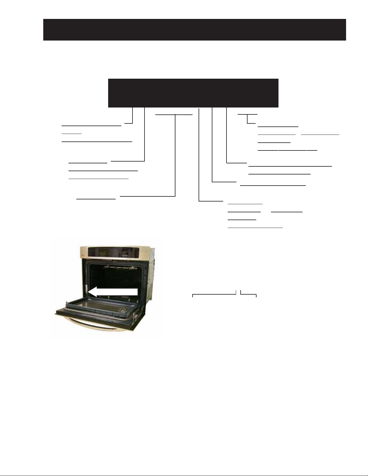
The nomenclature plate of the oven is
located on the left side of the front frame.
The Mini-manual is located in the control
compartment taped to the right side wall.
The nomenclature plate for the double wall
oven is located on the lower oven left side
of the front frame.
A
- JAN 2005 - H
D - FEB 2004 - G
F - MAR 2003 G - APR 2002 - D
H - MAY 2001 - A
L - JUN 2000 - Z
M - JUL 1999 - V
R - AUG 1998 - T
S - SEP 1997 - S
T - OCT 1996 - R
V - NOV 1995 - M
Z - DEC 1994 - L
– 7 –
F
The letter designating
the year repeats every
12 years.
Example:
T - 1974
T - 1986
T - 1998
Page 8
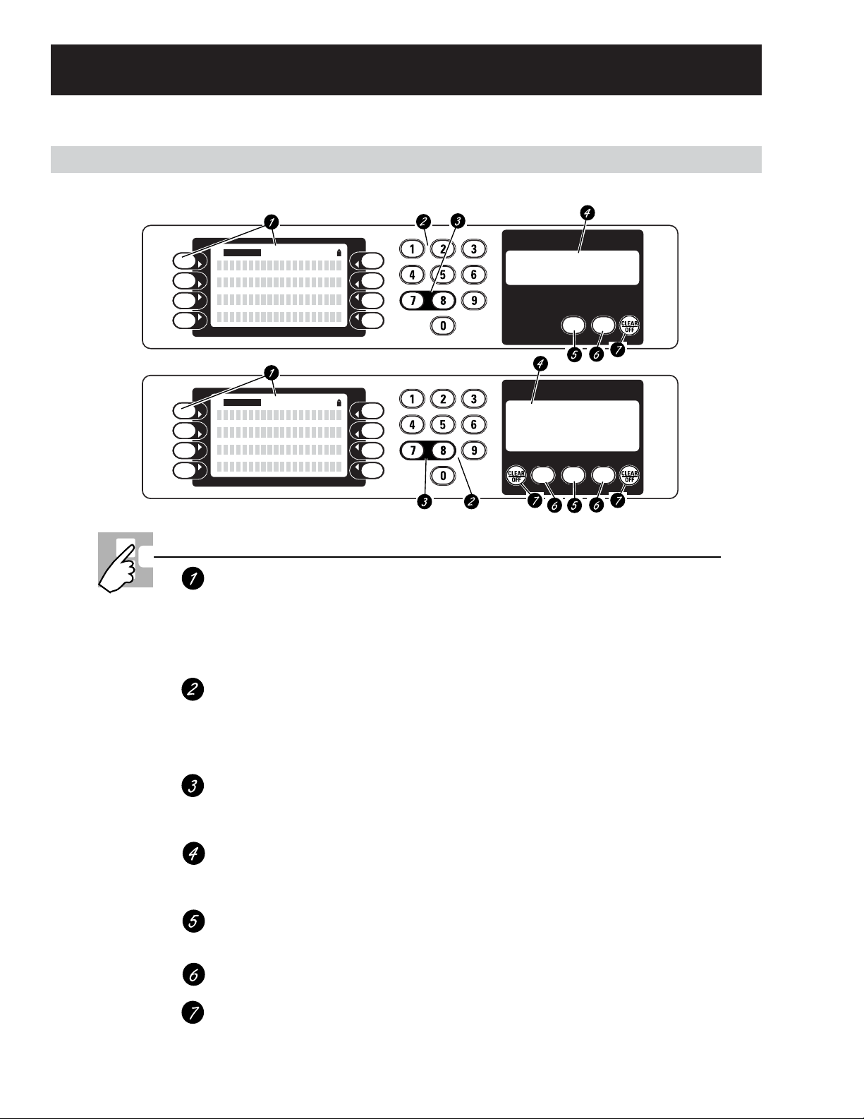
Using the Oven Controls
SELECT
Control Features
Single oven control.
Double oven control.
CONTROL LOCK
SELECT
CONTROL LOCK
Oven Control Layout and Description
Control Screen & Keypad
All cooking modes, special features and
oven settings are directed and operated
from the control screen. Directions for
operating the oven and prompting for
required information are displayed within
the control screen.
Numeric Keypad
Used to enter information requiring
numbers such as time of day on the clock,
timer, oven temperature, start time and
length of operation for timed baking and
self-cleaning.
Control Lockout
Allows the user to lock the control so that
the touch pads cannot be activated when
pressed.
Time and Temperature Display
All time and temperature information
is displayed in this area as feedback to
the user.
Kitchen Timer
Turns the kitchen timer on and off.
Does not control the oven.
Oven Light
Turns oven light on or off.
Clear/Off
Cancels ALL oven operations EXCEPT the
clock and timer.
If “F– and a number or letter” flash in the display and
the oven control signals, this indicates a function
error code. Press the CLEAR/OFF pad. Allow the oven to
cool for one hour. Put the oven back into operation. If the
function error code repeats, disconnect the power to the
oven and call for service.
If your oven was set for a timed oven operation
and a power outage occurred, the clock and all
programmed functions must be reset.
The time of day will flash in the display when there
has been a power outage.
OVEN
KITCHEN
TIMER
LIGHT
ON/OFF
UPPER OVEN LOWER OVEN
OVEN
LIGHT
KITCHEN
TIMER
ON/OFF
OVEN
LIGHT
– 8 –
Page 9
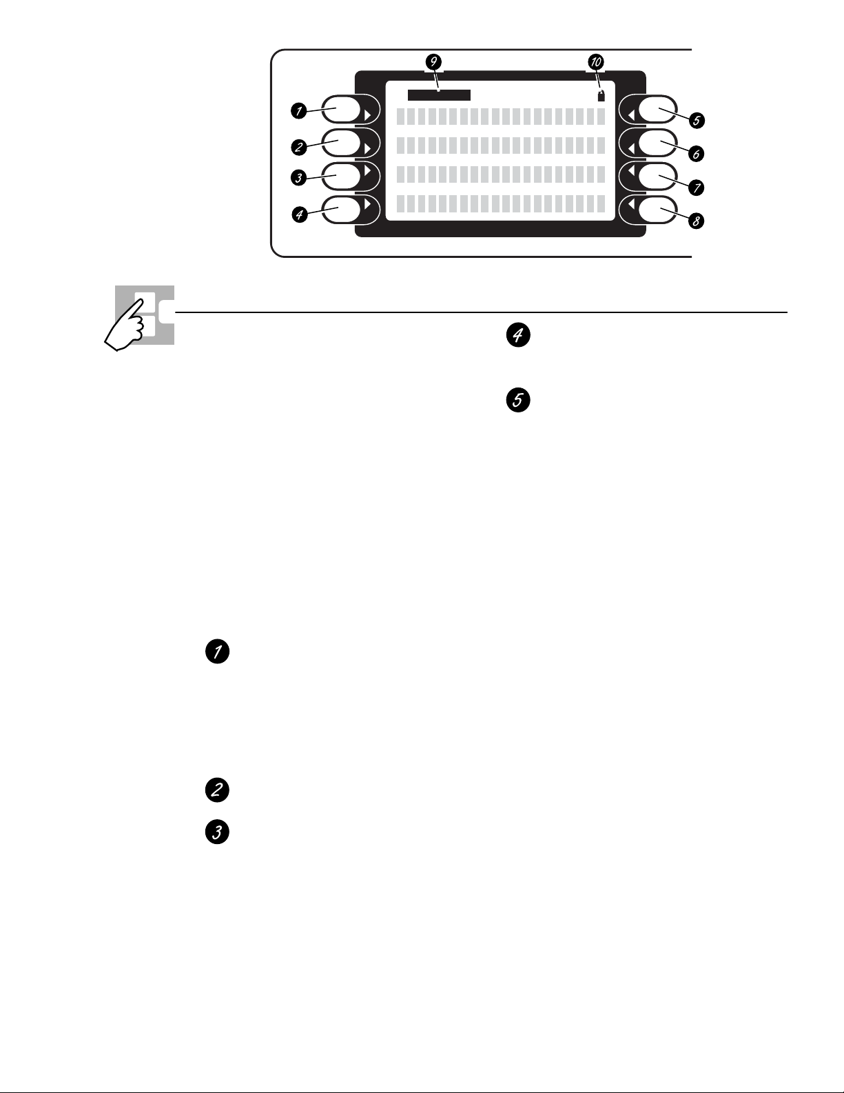
Press pad beside display to select item
in display.
Oven Control Sleep Feature—Any time the oven is
not in use (no cooking, no cleaning, no help and
no timers) for more than 10 minutes, the oven
control will go to sleep. While sleeping, the
control display will not show any text; it will go
blank. The clock will remain displayed in the time
and temperature display unless the “no clock”
option has been selected.
There will be no audible signal given to indicate
that the control is entering the sleep feature.
The control will enter the sleep feature even
when the control is locked.
The user cannot turn this feature OFF.
How to Exit the Sleep Feature—Touch any key. The
function associated with that key will not be started,
but the control display main menu will reappear.
Speedcook
In Speedcook mode, the user will be
prompted to enter food category,
temperature and cooking time.
Speed bake—Bakes food faster than
traditional cooking modes.
Speed broil—Broils food faster than
traditional Hi/Lo Broil.
Bake
Traditional bake mode.
Convection
Conv 1-Rack—Convection bake function
used for baking on one rack.
Conv Multi—Convection bake function
used for baking on more than one rack.
ConvRoast—Convection roast function.
Broil
LO & HI—Traditional broil function.
Speed broil
Features
Additional cooking-related features.
Defrost—This feature is used to thaw
frozen foods.
Self-Clean—This feature cleans the oven.
See the Using the self-cleaning oven section.
Warmer—This feature keeps hot, cooked
food warm for up to 3 hours. It is not
intended for reheating cold food.
Proof—This feature maintains a warm
environment useful for rising yeastleavened products. It is not intended to
keep food warm or reheat cold food.
Warm (Cook & Hold)—When this feature is
turned on, it will keep hot, cooked foods
warm for up to 3 hours following a Timed
Bake function.
Sabbath—Designed for use on the Jewish
Sabbath and Holidays.
SELECT
Control Screen and Keypad
(Continued next page)
– 9 –
Page 10
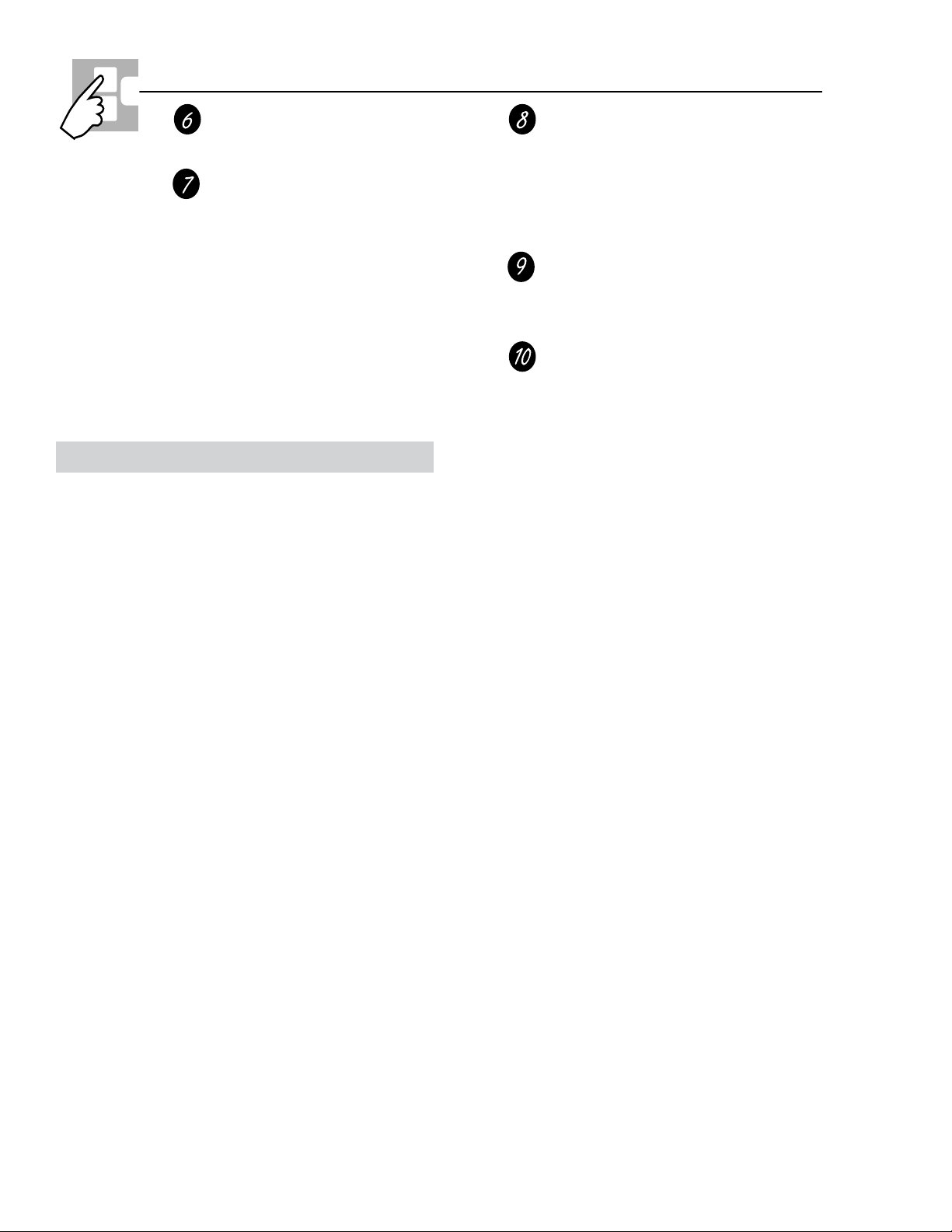
Control Screen and Keypad
Settings
This oven has additional settings that you
may choose to use.
NOTE: On double wall ovens, Recipes is
available only on the upper oven.
This oven feature allows the user
to store up to six temperature/cooking
time combinations. The user can then
speed bake, bake or convection bake/roast
one of the six stored favorite recipes
without having to choose the settings
each time.
Operational Notes
• The cooking loads (bake, broil, convection
elements, and microwave) are not energized
for 15 seconds after the cycle is started.
• In SPEEDCOOK, the time countdown will not
start until after the oven is preheated, the door
is opened then closed and START is pressed.
If START is not pressed, the microwave does
not start and the timer does not count down.
Help
Provides basic information on each
function and how to find the function.
If selected from the home screen, it gives
general help. If selected while performing
a function, it gives help on that function.
Select Exit to leave Help.
Select Prompt
Visual prompt to the user indicating
that a selection needs to be made from
the control screen.
Door Lock Indicator
Indicates that the oven door is locked
for self-clean.
• The convection fan may cycle on and off and
change direction while cooking to best
distribute hot air in the oven. The convection
fan shuts off when the oven door is opened.
• At least one cooling fan will automatically turn
on during all cooking modes. This fan turns on
to cool internal parts. It may run for up to 20
minutes (up to 85 minutes for double oven
models) after the oven is turned off,
regardless of oven temperature.
• In SPEEDCOOK, if the door is opened during
the cooking cycle, the timer, microwave and
convection fan will stop. The elements will
continue to cycle on when necessary. Once
the door is closed, the convection fan and
microwave will operate and the timer
countdown will resume.
• In DEFROST, the microwave turns off and the
cook time stops counting down when the oven
door is opened. They will resume when the
door is closed.
• PROOF will not operate when oven is above
125°F. OVEN TOO HOT will show in the
display.
• In PROOF and DEFROST, the convection fan
will rotate for 1 minute in one direction, then
turn off for 10 minutes. Af ter 10 minutes, the
fan will rotate for 1 minute again, in the
opposite direction.
• When the oven first starts heating, the
temperature display will start at 100°F.
• On double oven models, you can set a delay
clean in both ovens. However, the second
oven set will automatically delay the start of
cleaning until the end of the first oven’s clean
cycle.
• The RECIPES feature allows you to preset up
to six temperature/cooking time combinations
with this function. You can then bake,
convection bake/roast or speed bake any of
these six favorite recipes without choosing
settings each time. You cannot program broil,
defrost, warmer, proof, speed broil, delay bake
or self-clean in RECIPES.
• The oven will remember RECIPES that have
been programmed, even after a power outage.
The cooking time you enter does not include
preheat time. The oven will begin to count
down the cooking time after the oven has
completed preheating. RECIPES are only
available on the upper oven of a double wall
oven.
– 10 –
Page 11

• On double oven models, you can use timed
baking or roasting in one oven while using
self-clean in the other; you can also use timed
baking or roasting in both ovens at the same
time. You will hear a fan while cooking with
these features.
Control Lockout (Single and Double Wall
Ovens)
• Press the 7 & 8 pads at the same time for 3
seconds. The screen will display CONTROL
IS LOCKED.
• To unlock the control, press the 7 & 8 pads for
3 seconds. The display will return to the home
screen.
• To turn this feature off, press the BACK pad
for 3 seconds. The control returns to the
FEATURES screen where SABBATH was
originally selected.
Note: This feature remains active even after loss
of power to the oven. The only way to exit
SABBA TH is to hold the BACK p ad for 3 seconds.
If power is lost while the Sabbath mode is in a
heating cycle, the heat will be off when the power
is restored.
Sales Mode
• Becomes active upon powering up with 120V
only (L1-L2 = 120V , L2 connected to N).
Control Lockout (Slide-In Range)
• Press the CONTROL LOCK pad for 3
seconds. The screen will display CONTROL
IS LOCKED.
• To unlock the control, press the CONTROL
LOCK pad for 3 seconds. The display will
return to the home screen.
If any cooking/cleaning modes are running,
entering control lockout will cancel the cooking/
cleaning modes. Then when exiting control
lockout, it will go to the home screen.
Sabbath Feature
• This feature disables all but the bake and
timed bake modes. Additionally the display
does not show the temperature and the sound
is disabled.
• The element and oven icons will light
randomly within one minute to indicate that the
oven is operating. All time functions will remain
displayed and active.
• To access the sabbath feature, press the
FEA TURES pad, then the MORE p ad.
• To turn this feature on, press the SABBATH
pad.
• This mode is NOT accessible on 240V/208V
power input. Sales mode requires a special
120 V AC cord (oven L1 connected to power
cord L, oven L2 and N connected to power
cord N).
• Wall Oven cord kit is Pub # 3-A063
Slide-In cord kit is Pub #3-A073.
Time Settings
• To access the time settings, press the
SETTINGS pad on the home screen, then
press the appropriate time function pad.
Oven Calibration
Oven calibration offset can be adjusted for the
bake mode only . No other cooking modes are
affected by changing the bake mode temperature.
1. Press the SETTINGS pad.
2. Press the MORE pad until ± TEMP appears in
the display .
3. Press the ± TEMP pad. (Select upper or lower
oven for double oven models.)
4. Press the INCREASE or DECREASE pads to
change the cooking temperature in 1°
increments up to ±35°F.
Note: Oven calibration offset can also be
accessed through the service mode under
OFFSET. (See
Service Mode.)
– 11 –
Page 12
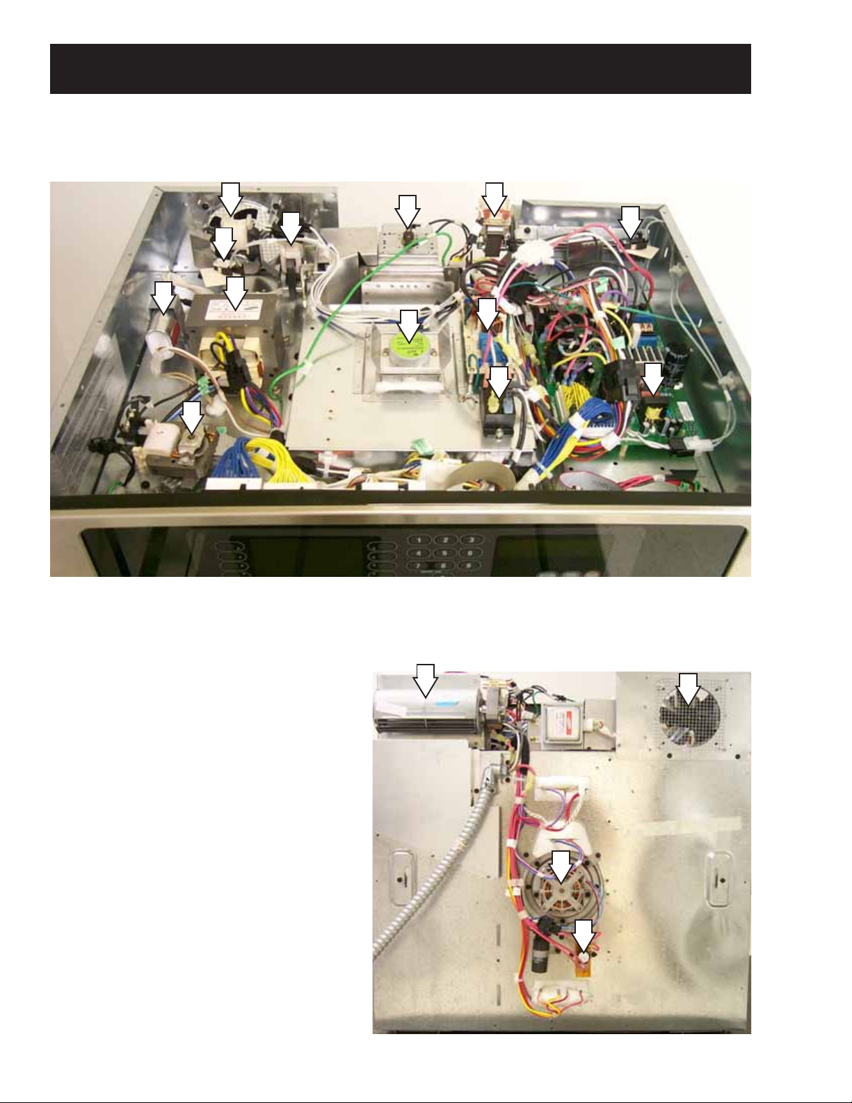
30-in. Single Wall Oven
Component Locator Views
11
3
5
4
10
2
1
6
7
12
9
8
15
1 - Magnetron Thermal TCO (Thermal Cutout)
2 - High Voltage T ransformer
3 - Magnetron Cooling Fan
4 - High Voltage Capacitor
5 - Left Sail Switch
6 - Stirrer Motor
7 - EMI Filter Board
8 - R1 Sail Switch Relay
9 - Right Sail Switch
10 - Oven Vent Fan
11 - High Voltage T ransformer (HVT) Fan
12 - Right Cooling Fan
13 - Convection Fan
14 - High Limit Thermal One-Shot (TCO)
15 - Main Power Board (MPB)
12
Rear View
11
13
14
– 12 –
Page 13
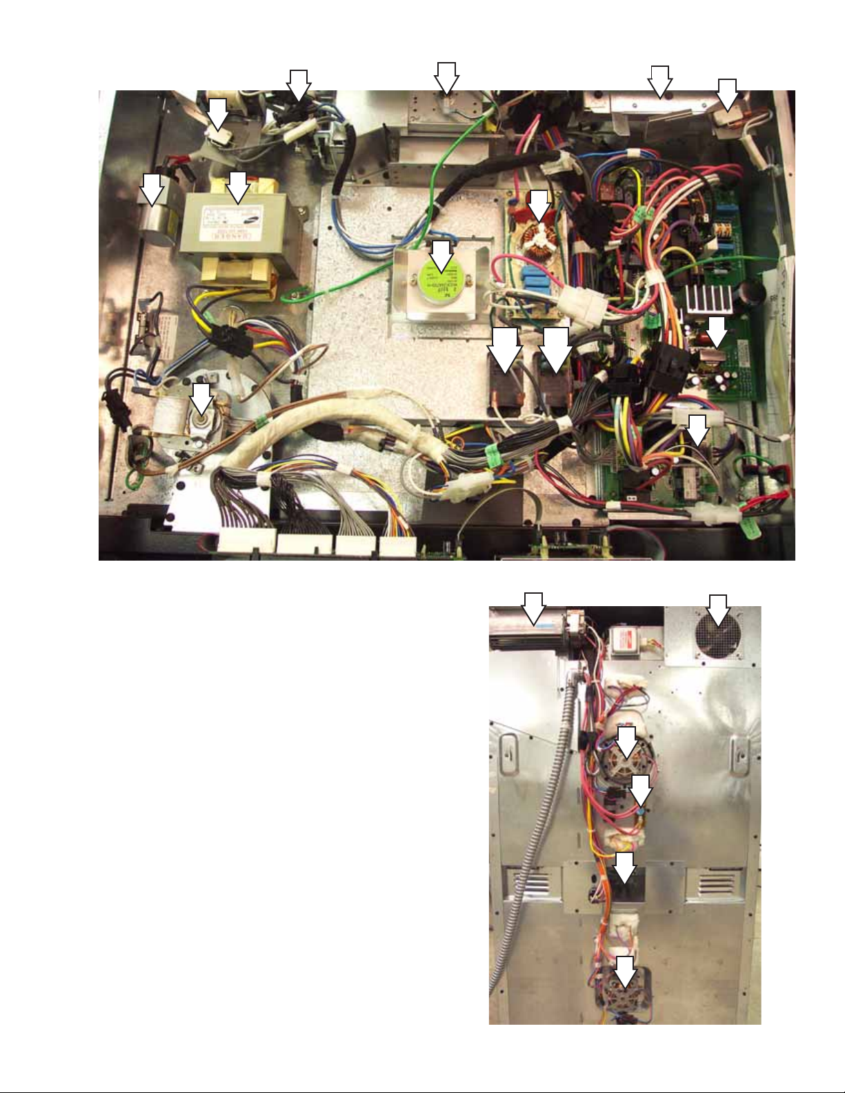
30-in. Double Wall Oven
5
3
1
12
9
4
2
7
6
17
8a 8b
10
15
1 - Magnetron Thermal TCO (Thermal Cutout)
2 - High Voltage T ransformer
3 - Magnetron Cooling Fan
4 - High Voltage Cap acitor
5 - Left Sail Switch
6 - Stirrer Motor
7 - EMI Board
8 - (a) R2 and (b) R1 Sail Switch Relay
9 - Right Sail Switch
10 - Oven Vent Fan
11 - High Voltage T ransformer (HVT) Fan
12 - Right Cooling Fan
13 - Convection Fan
14 - High Limit Thermal One-Shot (TCO)
15 - Lower Oven Relay Board
16 - Lower Oven Cooling Fan
12
Rear View
11
13
14
16
13
17 - Main Power Board (MPB)
– 13 –
Page 14
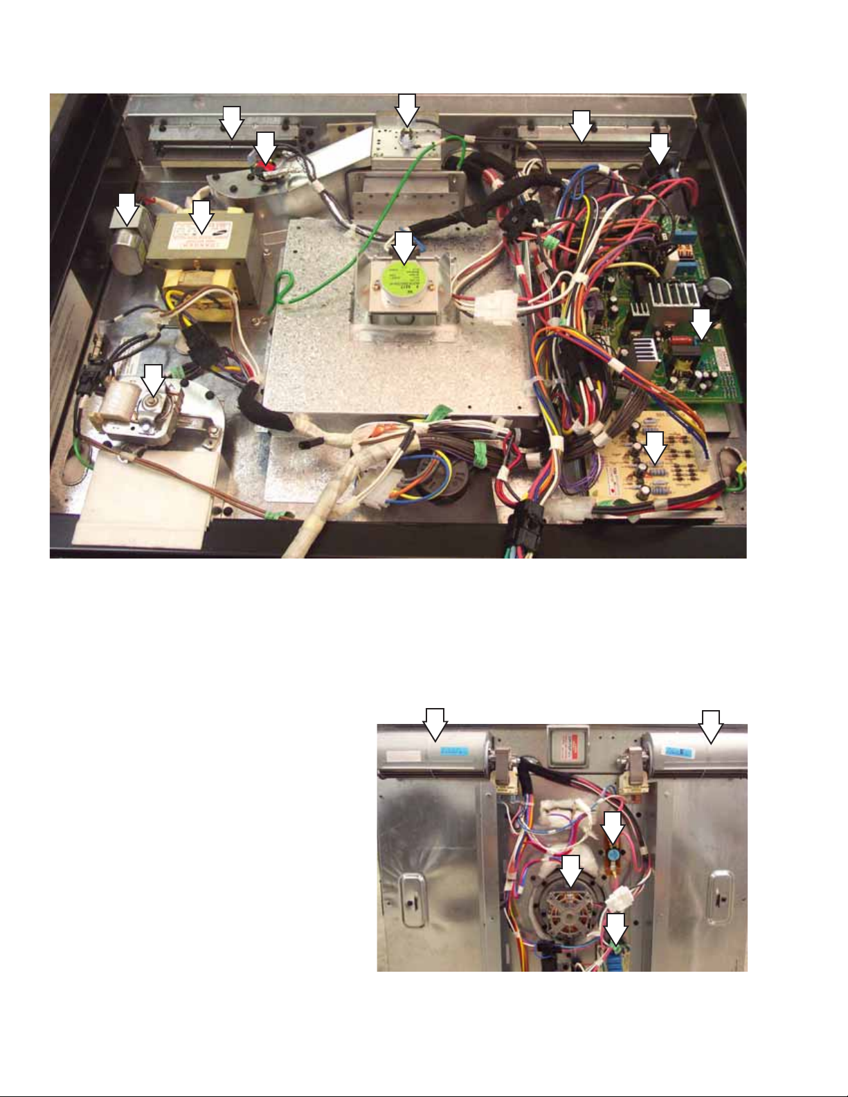
30-in. Slide-In Range (
Shown with Cooktop Removed)
8
3
5
7
2
1
9
4
6
14
12
1 - Magnetron Thermal TCO
2 - High Voltage T ransformer
3 - Left F AD (Fan Apparency Device) TCO
4 - Right FAD TCO
5 - High Voltage Capacitor
6 - Stirrer Motor
7 - Oven Vent Fan
8 - Left Cooling Fan
9 - Right Cooling Fan
10 - High Limit Thermal One-Shot (TCO)
11 - Convection Fan
12 - Current Limit Board (CLB)
13 - EMI Filter Board
14 - Main Power Board (MPB)
Rear View
9
8
10
11
13
– 14 –
Page 15
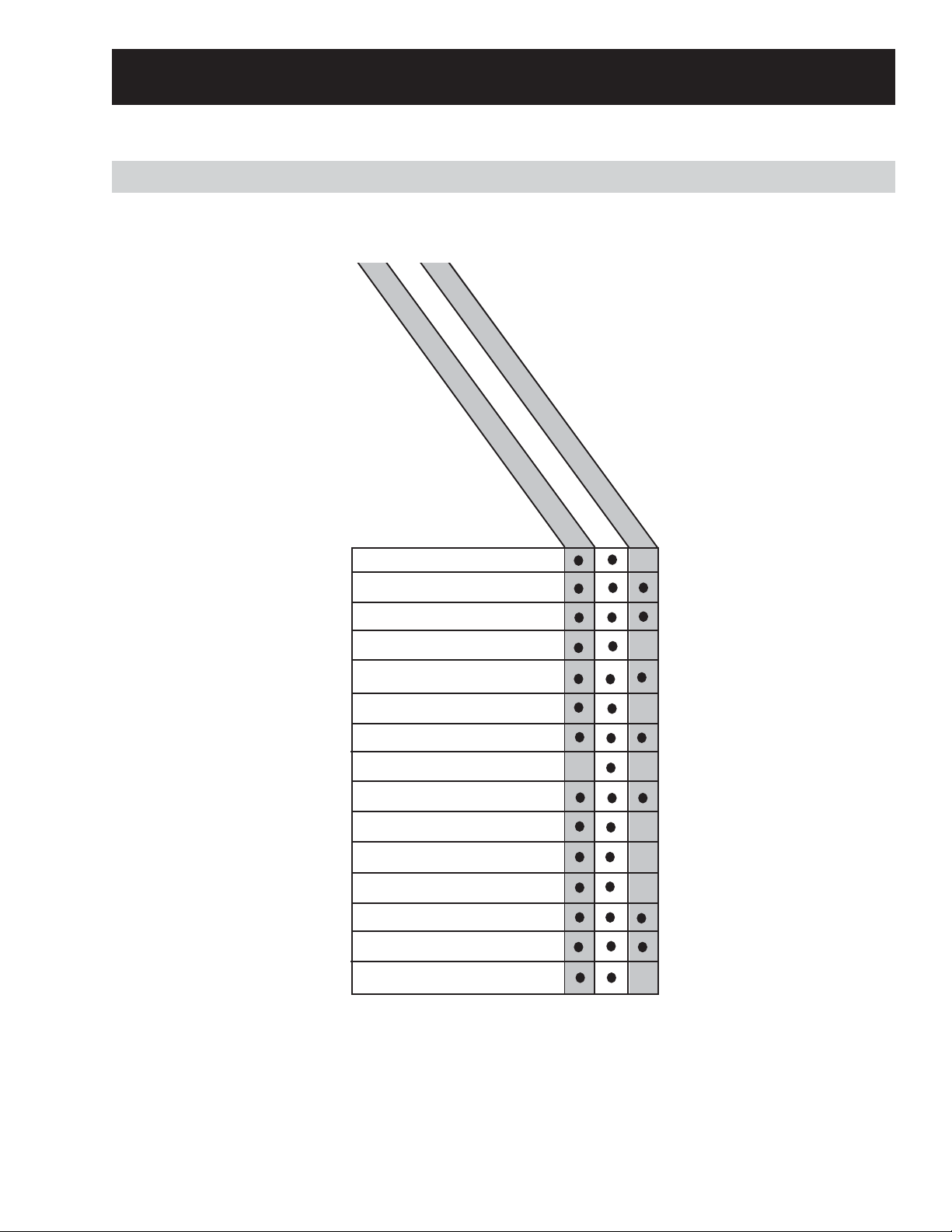
Oven Components
Components Requiring Oven Removal
To replace the components listed below, the oven must be removed from its installation.
Double Wall Oven
Single Wall Oven
Slide-In Range
Capacitor
Convection Fan Capacitor
Convection Fan Motor(s)
Diode
EMI Board
High Volt age Transformer
Left Cooling Fan
Lower Oven Cooling Fan
Magnetron
Magnetron Cooling Fan
Magnetron TCO
Main Power Board
One-Shot Thermostat
Right Cooling Fan
Sail Switches
NA
Note: When assembling, the elements, convection fan, and oven light contain special radiation screens
and chokes. Be sure to replace these in the oven cavity. Take special care not to strip any screws when
replacing these components.
– 15 –
Page 16
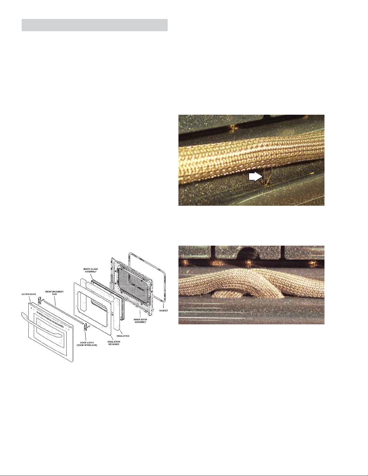
TrivectionTM Door Assembly
WARNING: A microwave leakage test must be
performed any time a door is removed, replaced,
disassembled, or adjusted for any reason. The
maximum leakage is 4 MW/cm
Microwave Leakage Test).
2
(see
Caution: Care must be taken if reinstalling the
door handle. Overtightening screws can damage
handle. Hand-tighten screws and make sure
handle fits snugly to door panel (do not use
electric driver).
To remove the Trivection
TM
Door Gasket:
Caution: The door is very heavy. Use the correct
lifting procedures. Do not lift the door by the
handle.
To remove the Trivection
TM
door:
1. Fully open the door.
2. Remove the security screws and clips on
each hinge with a Torx 20 (T20) screwdriver.
3. Pull the hinge locks down toward the door
frame, to the unlocked position. (This may
require a flat-blade screwdriver to start the
hinge locks moving).
4. Firmly grasp both sides of the door at the top.
5. Close the door to the door removal position,
which is halfway between the broil stop
position and fully closed.
6. Lift the door up and out until the hinge arm is
clear of the slot.
The door gasket is attached to the inner door
panel by spring clips. In addition to being a selfclean gasket, the door gasket has a wire mesh to
help seal microwave energy .
Cross the gasket and tuck loose ends into the
slots at the bottom of inner panel as shown below.
To remove the outer door:
1. Place the inner door side down on the work
area.
2. Remove the eight T15 Torx screws from the
outer door (two on each side, four across the
bottom).
3. Lift the outer door and handle off the door
assembly.
Note: There is no gap at the bottom of the gasket
on the TrivectionTM oven door.
To remove the inner glass assembly:
1. Remove the eight
1
/4-in. hex head screws
holding the insulation retainer .
2. Remove the retainer and insulation.
3. Lift the inner glass assembly off the inner
door.
– 16 –
Page 17
Bulb
Socket
Ta b
Glass cover
Receptacle
Screen
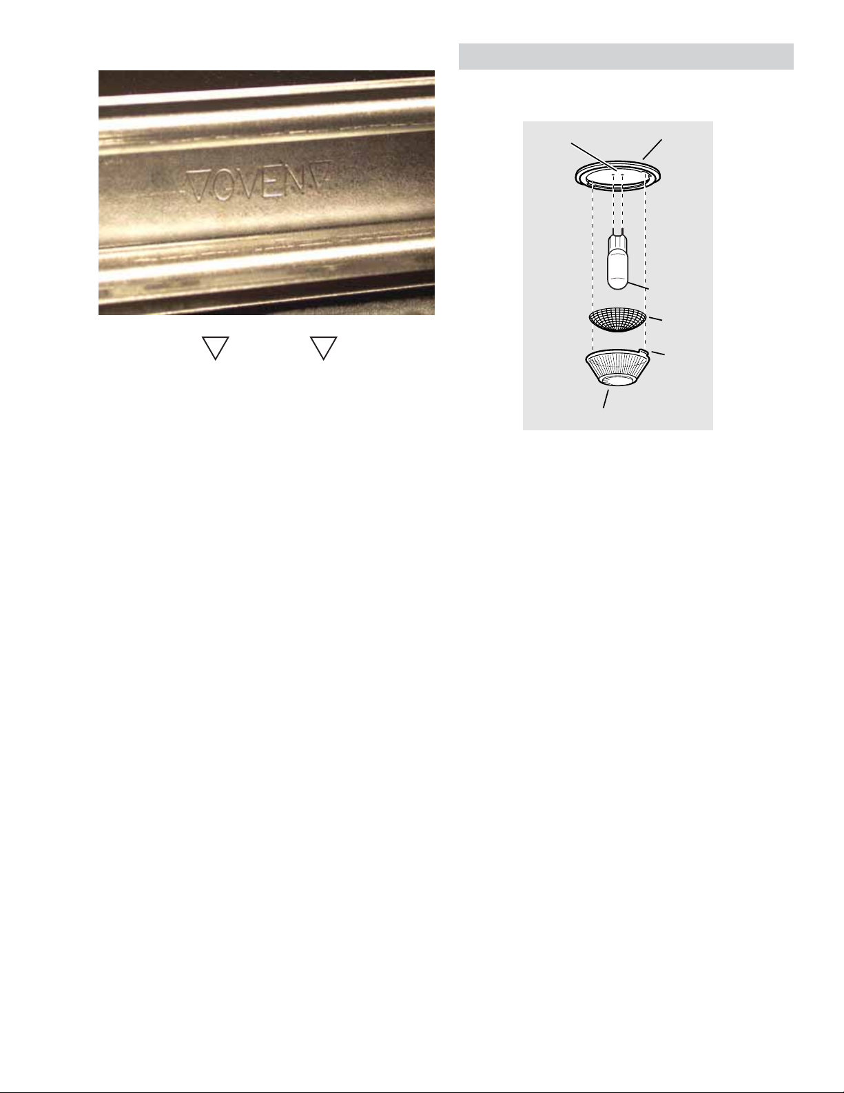
Inner Glass Assembly
OVEN
Note: Arrows on the side of the inner glass
assembly indicate the direction in which the oven
door glass is installed. The arrows should be
pointing toward the oven cavity .
Oven Light Bulb Assembly
Inner Door Assembly
The inner door liner, glass and hinges are one
assembly and should NOT be separated. All the
screws on the inner door assembly have been
®
torqued to a specific setting and Loctite
sealant
applied to prevent microwave leakage.
To replace the Trivection
TM
door:
1. Firmly grasp both sides of the door at the top.
2. With the door at the same angle as the
removal position, seat the indentation of the
hinge arm into the bottom edge of the hinge
slot. The notch in the hinge arm must be fully
seated into the bottom of the slot.
3. Fully open the door. If the door cannot be fully
opened, the hinge is not properly seated.
4. Push the hinge locks up against the front
frame of the oven cavity , to the locked
position.
5. Reinstall the security screws on each hinge.
6. Close the oven door and check for proper
alignment, rubbing, etc.
7. Perform the Microwave Leakage Test.
Note: On slide-in models, the door rubbing on the
oven cavity may be due to the leveling legs. If the
oven is not level it can "rack" the cavity and cause
rubbing.
Note: The glass cover should be removed only
when cold. Be sure to let the light cover and bulb
cool completely . Do not touch a hot bulb with bare
hands or a damp cloth.
Replace with a new 130V halogen bulb, not to
exceed 50 watts.
Note: Bulbs are 50 watt in Trivection
TM
oven, and
30 watts in the lower oven of double oven.
To remove and replace the oven light bulb:
1. Turn the glass cover counterclockwise
1
/4 turn
until the tabs of the glass cover clear the
grooves of the socket.
2. Using gloves or a dry cloth, remove the bulb
by pulling it straight out.
3. Using gloves or a dry cloth, remove the new
bulb from its packaging. Do not touch the bulb
with bare fingers.
4. Push the bulb straight into the receptacle all
the way. Then replace the screen.
Note: The screen must be replaced or the life of
the bulb will be reduced.
– 17 –
Page 18
TrivectionTM Bake, Broil and Convection
Elements
WARNING: A microwave leakage test must be
performed any time an element is removed,
replaced, or adjusted for any reason. The
maximum leakage is 4 MW/cm
Microwave Leakage Test).
Caution: Use caution when removing element
from inside oven cavity due to wire harness
layout. There is a possibility of the wire terminals
coming loose from the element when pulling the
wires through the oven cavity .
Note: When reconnecting the elements, make
sure the connectors are securely attached to the
element terminals.
The bake and broil elements have special gaskets
that keep microwave energy from leaking out of
the oven cavity . Replace any worn or damaged
gaskets.
2
(see
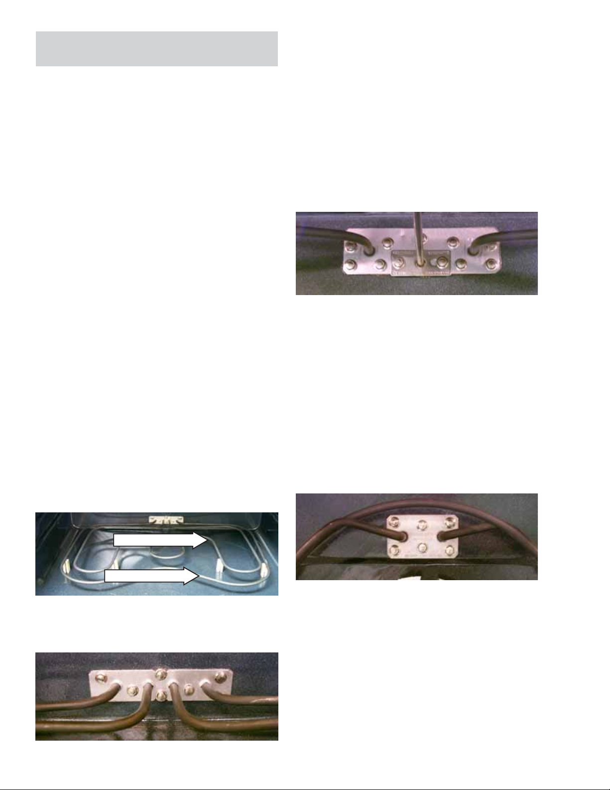
Broil Element
• The broil element is rated at 2500 watts, has
an approximate resistance value of 22 Ω, and
draws approximately 9 amps.
• The broil element is held is place on the back
oven wall by:
a. Eleven
1
/4-in. hex head screws on the
mounting plate.
1
b. T wo
-
/4
in. hex head screws on the left and
right element brackets.
Convection Element
Bake Element
• The bake element is composed of an inner
and an outer element. It is replaced as one
unit.
• The inside element is rated at 2500 watts, has
an approximate resistance value of 22 Ω, and
draws approximately 9 amps.
• The outside element is rated at 900 watts, has
an approximate resistance value of 63 Ω, and
draws approximately 3.2 amps.
Inner Element
Outer Element
• The bake element is held is place on the back
oven wall by six 1/4-in. hex head screws.
• The convection element is rated at 2500
watts, has an approximate resistance value of
22 Ω, and draws approximately 9 amps.
• The convection element is held in place on the
back oven wall by:
a. Six
1
/4-in. hex head screws on the
mounting plate.
b. One
1
/4-in. hex head screw on the bottom
element bracket.
Note: Production will be using Torx (T20H)
security screws on all elements in the Trivection
TM
oven in the near future.
– 18 –
Page 19
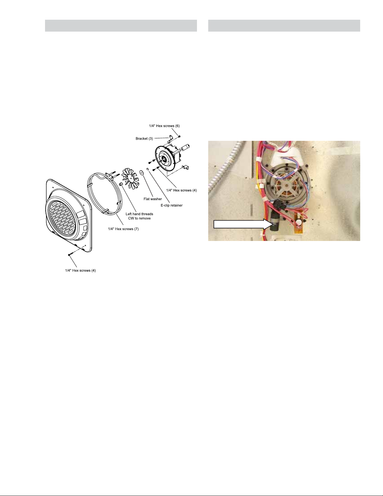
Trivection
TM
Convection Fan Assembly
TrivectionTM Convection Fan Motor
The convection fan assembly consists of the fan
guard, element, fan blade, and motor.
Refer to the schematic in the back of this manual
for circuitry for your specific model.
Trivection
TM
Convection Fan Assembly
The convection fan motor is located on the back
of the oven.
The convection fan motor has approximate
resistance values between the following wires:
• Red and Blue: 118 Ω
• Red and Black: 58 Ω
• Blue and Black: 58 Ω
Wall Oven Shown
• The element cover is held in place by four
1
/4-in. hex head screws.
• The convection fan blade nut has left-hand
threads. Turn nut clockwise to remove.
Motor Capacitor
• To remove the convection fan motor:
a. Remove the four
1
/4-in. hex head screws
on the inside of the oven cavity .
b. On the back on the oven, remove the 3
1
outer
/4-in. hex head screws from the 3
brackets that hold the convection motor in
place.
Note: The convection fan assembly in the lower
oven of the double oven mounts the same as
previous convection fan assemblies.
– 19 –
Page 20
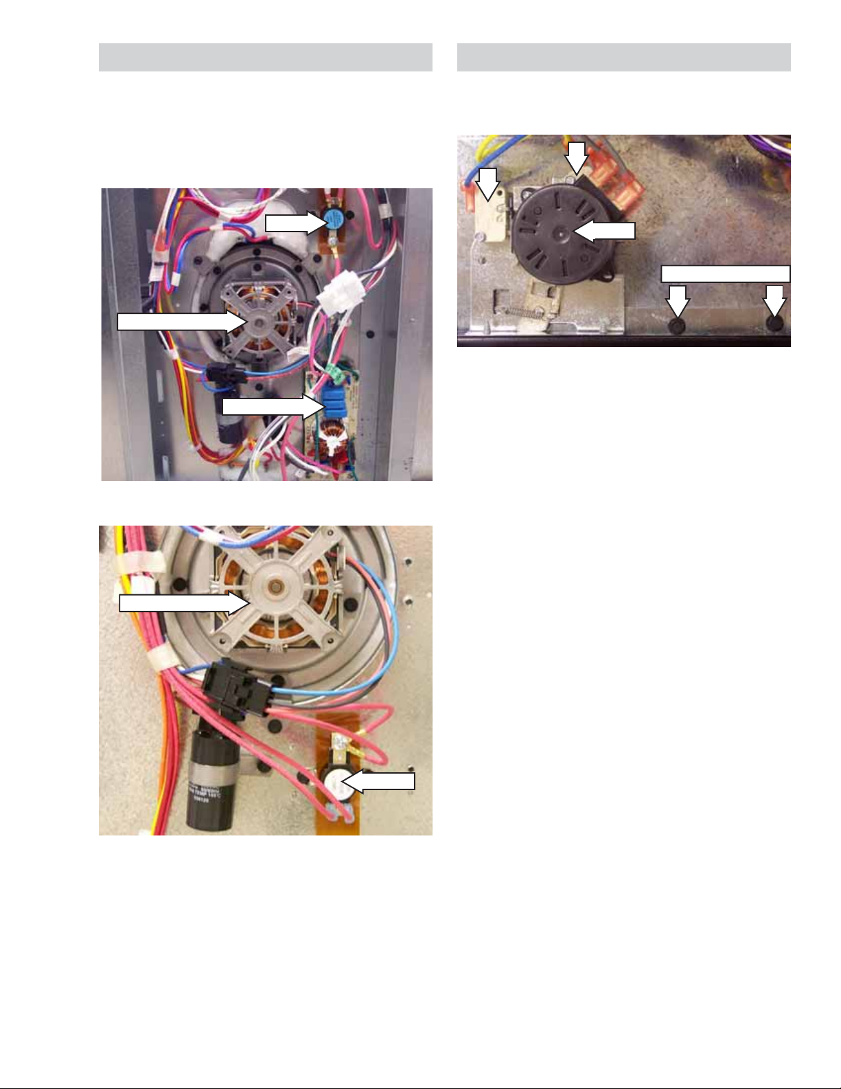
Oven T emperature Sensor (RTD)
Lower Cooling Fan (Double Wall Oven Only)
The RTD ( Resistive Thermal Device) has a
resistance of 1100 Ω at room temperature and
2650 Ω at clean temperature.
Sensor
Right Cooling Fan
The right cooling fan is located in the right rear
corner of the control compartment and has an
approximate resistance value of 19 Ω.
The lower cooling fan is located between the
upper and lower ovens, and has an approximate
resistance value of 68 Ω.
The fan can only be removed from the back of the
oven.
Right Fan
Rear View
Note: The right cooling fan and the lower cooling
fan of the Double Wall Oven are controlled by a
single relay .
Right Fan
– 20 –
Page 21
Sail Switches (Double and Single Wall Ovens)
• The left and right sail switches are normally
open limit switches located at the rear of the
component compartment in front of the
cooling fans.
• The sail switches monitor the presence of the
airstream from the fans. If either fan (HVT fan
or right cooling fan) malfunctions, the
applicable sail switch opens and opens relay
R1, which disables power to the microwave
HVT and oven cooking elements. In addition, if
the right cooling fan malfunctions on the
double oven, the right sail switch opens and
opens relay R2, which disables the lower
oven cooking elements.
• The relay coil resistance is approximately
920 Ω.
• It is normal for steam to come out of this vent
and the area around the vent to become hot
during oven use. It is important to keep the
vent unblocked to ensure proper air
circulation.
• The oven vent fan motor has an approximate
resistance value of 20 Ω and rotates
clockwise as viewed from the top.
• To remove the vent fan assembly, remove the
four 1/4-in. hex nuts from inside the oven
cavity.
Vent Fan
Left Sail Switch
• Both R1 relay and R2 relay (double oven only)
are double pole single throw relays. Both
contacts are used on R1, only one contact is
used on R2.
Oven V ent Fan
The oven is vented above the left side of the door .
Vent Fan Motor
Note: All vent fan p arts are available sep arately.
Vent Fan Blade
The vent fan blade nut has right-hand threads.
Turn nut counterclockwise to remove.
– 21 –
Page 22
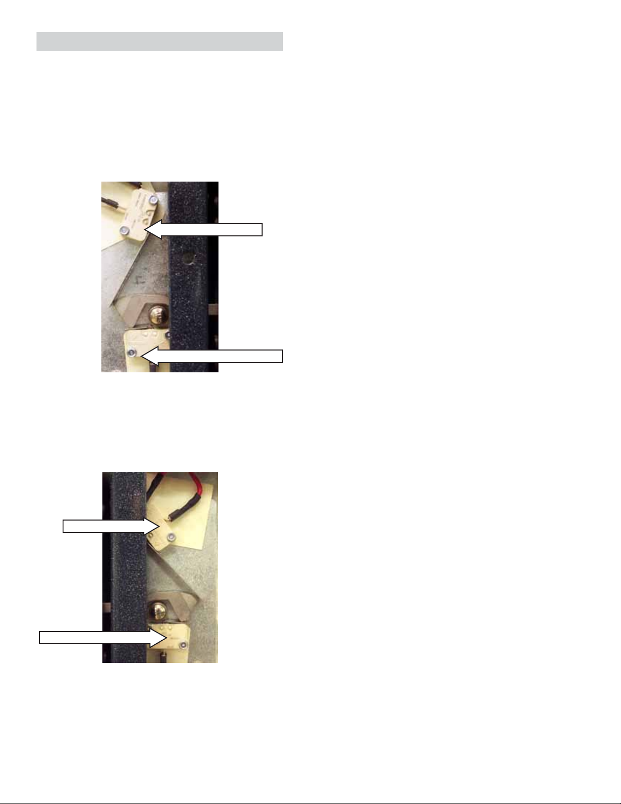
Lower Oven Bake and Clean Thermal
TCO's (Double Wall Ovens)
Left and Right Thermal TCO's (Slide-In
Range)
The bake and clean FAD's (Fan Apparency
Device) TCO's are located between the upper
and lower ovens on the floor of the component
compartment in front of the fan motor. They are
monitored by the controls software.
Both lower oven clean and bake FAD's are
ignored by the control when the upper oven is in
self-clean.
Bake
Clean
The left and right F AD's (Fan App arency Device)
TCO’s are located at the rear of the component
compartment, in front of the respective cooling
fan.
Left FAD
Right Fan
Bake FAD
• Is wired in series with the lower door unlock
motor switch.
• Opens at 185°F and closes when cooled
below 158°F .
• The bake FAD can only be detected by the
control when in non self-clean operations
(unlock switch closed, lock switch open).
Higher Temperature (
Clean) FAD
• Is wired in series with the common of the lock/
unlock switch.
• Opens at 275°F and closes when cooled
below 205°F .
• The clean FAD is always detected by the
control.
If the thermal switch opens in any mode of
operation, the control will display F9 failure code.
When this condition exists, check for proper fan
operation (look for obstructions), and inspect oven
installation (make sure grille areas are not
blocked), oven insulation and lock/unlock circuit of
lower door lock.
Right FAD
• Both remove power from the controls when
open.
• Both are normally closed and wired in series
with the magnetron TCO, supplying L1 to the
main power board to power the controls.
• The left F AD opens at 185°F and closes when
cooled below 158°F. The right TCO opens at
194°F and closes when cooled below 167°F.
• If either FAD opens, check for proper fan
operation.
• Each FAD has an internal heater. N is
connected to one side of the heaters, and L2
is connected to the other side through the
convection DLB relay. The heaters are
powered when the DLB relay is energized.
The DLB relays are energized continuously in
in Service Mode and any cooking or clean
mode.
– 22 –
Page 23
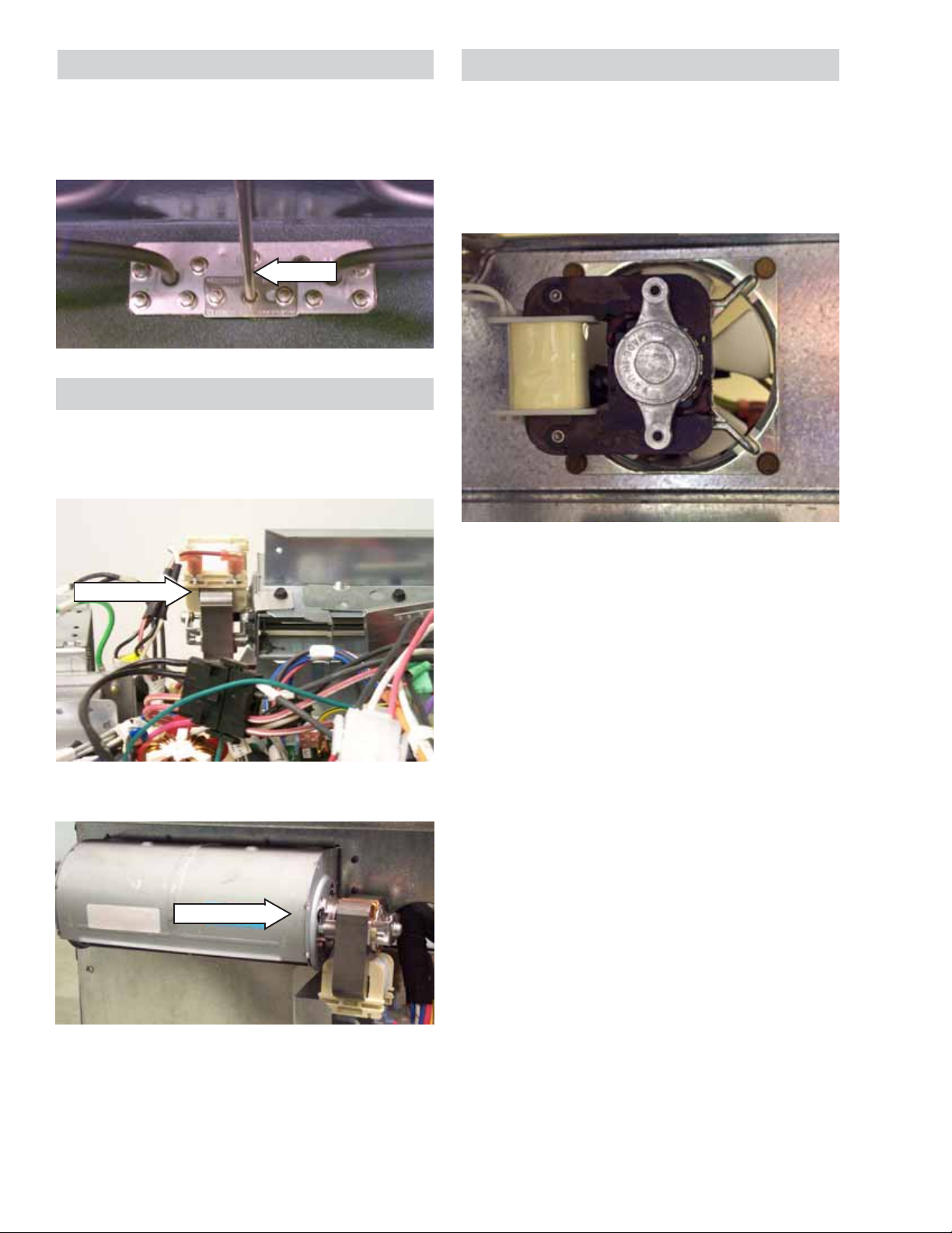
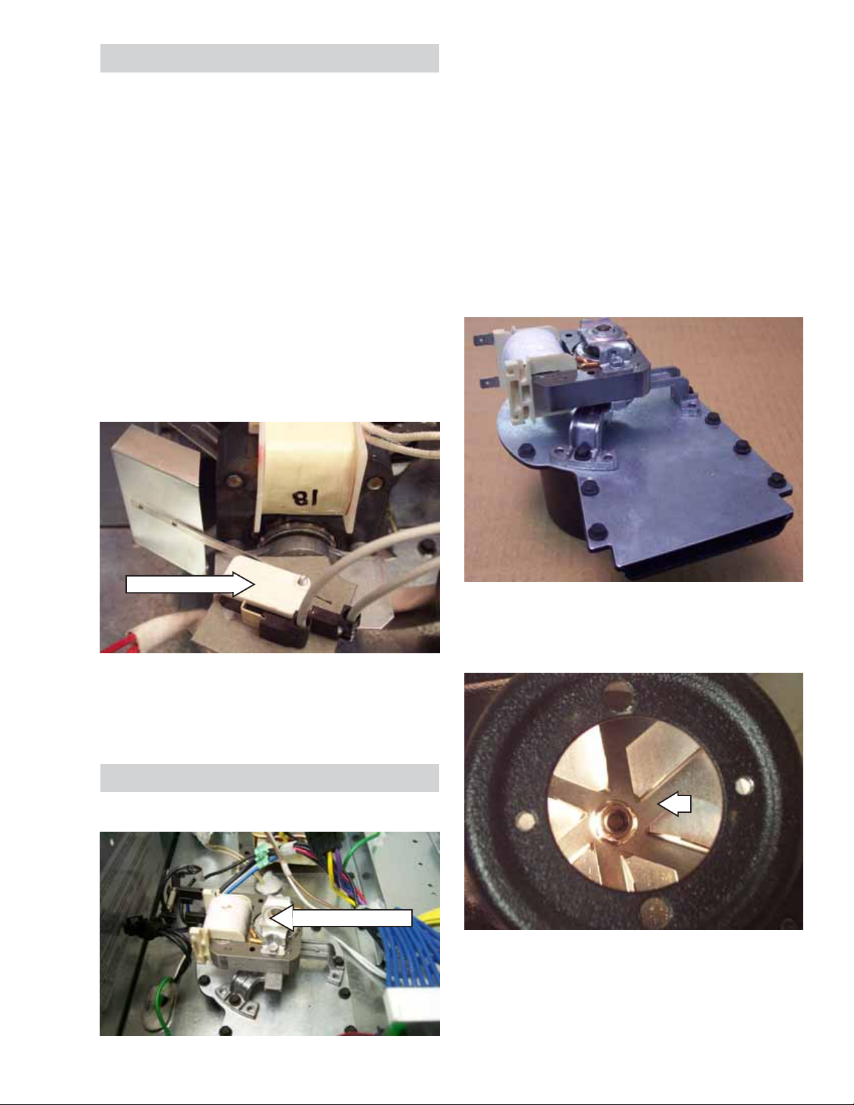
High Limit Thermal One-Shot TCO
Self-Clean Latch Motor
The high limit thermal one-shot TCO is located on
the rear of the oven behind the center cover and is
wired in series with L2 from the terminal block.
Slide-In Range
TCO
Convection Fan
EMI Board
To remove the self-clean latch motor assembly,
remove the two 1/4-in. hex head screws.
2
1
Motor
Hex Head Screws
1 - Unlock Switch
• Blue and yellow wires.
• Reads closed when the door is unlocked.
Single and Upper Double Wall Ovens
Convection Fan
TCO
• These thermal switches are a non-resettable
device and will open at 302°F, indicating a
thermal runaway condition.
2 - Lock Switch
• Orange and yellow wires
• Reads infinity when the door is unlocked.
• If tripped, the oven must be removed from
installation in order for the one-shot TCO to be
replaced.
• Cause of overheating should be determined
before replacing the TCO.
– 23 –
Page 24
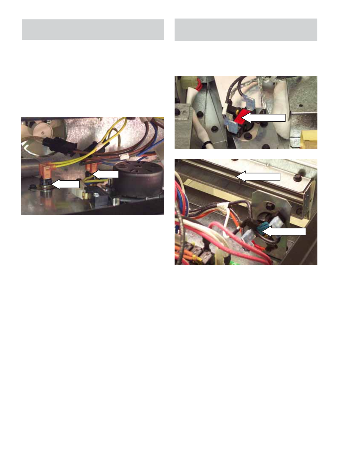
Door Switches
Oven Door Sense Switch
Safety Interlocks
The microwave interlock system has a left and a
right interlock assembly.
Left Interlock Switch Assembly - Door sense
switch (NO) and secondary interlock switch (NO)
with two 2 position connectors with black and
brown wire outputs.
Left Side Door Switches
Door Sense Switch
Secondary Interlock Switch
The oven door sense switch is located in the left
interlock assembly on the Trivection
TM
oven.
Proper operation of the door sense switch is
required for proper operation of the microwave,
oven light, convection fan and the door lock.
To check the door sense switch:
1. Enter the service mode (see
Service Mode).
2. Select DOOR POSITION option and observe
the display as the door is opened and closed.
3. If the state (open/closed) does not change on
the display , turn of f power and check wiring
and switch with ohmmeter.
Interlock and Monitor Switches
Proper operation of the interlock switches and
monitor switch are required for proper operation of
the microwave system. When troubleshooting or
replacing interlock switch assembly, follow the
procedure outlined below to verify proper switch
operation.
Right Interlock Switch Assembly - Interlock
monitor switch (NC) and primary interlock switch
(NO) with one 4-position connector with red and
black wire outputs.
Right Side Door Switches
Monitor Switch
Primary Interlock Switch
Note: Replace entire left side door switch
assembly or right side door switch assembly. Do
not replace the individual switches. Switch
positions and interlock actuation distance are
controlled by assembly of switch-to-mounting
bracket. Do not replace or adjust individual
switches on door switch assembly.
To check the primary and secondary interlock
switches:
1. With power off, attach meter probes to the
leads of each switch.
2. Verify the following:
• Closed door circuit must have continuity.
• Opened door circuit must read open.
To check the monitor switch:
1. With power off, attach meter probes to the
leads of each switch.
2. Verify the following:
• Closed door circuit must read open.
• Opened door circuit must have continuity.
Important: Any defective or misadjusted
components in the interlock monitor , door seal,
microwave generation and transmission systems
shall be repaired, replaced, or adjusted by
procedures described in this manual before the
oven is released to the owner.
– 24 –
Page 25

Control Panel (Double and Single Wall Ovens)
Cooktop (Slide-In Range)
Removal and Replacement
1. Remove the three 1/4-in. hex head screws
securing the control panel to the vent trim.
Note: Screws are located under the control panel
and can be accessed by opening the oven door
and removing them from the bottom.
2. The panel has keyhole slots at the top and is
held very tight. Carefully push the panel up,
then pull out at the bottom.
Glass Touch Assembly (Slide-In Range)
Removal and Replacement
1. Disconnect power to the range.
2. Remove all surface unit knobs.
3. Unscrew the four plastic crystal retainers on
the infinite switches by turning counterclockwise.
Removing and Replacement
1. Remove the Glass Touch Assembly.
2. Remove the
Control Panel Insert.
3. Remove the control panel trim by removing
the five
front edge of the cooktop and the five
1
/4-in. hex head screws attached to the
1
/4-in.
hex head screws at the bottom attached to the
vent trim.
Note: The retainers should only be hand tightened
when reinstalling.
4. Lift the glass touch assembly 3 inches away
from the control panel and unplug the ribbon
cable from the assembly.
Note: The ribbon cable and connector are very
fragile. Take extra care when removing. When
reassembling, do not pinch the ribbon connector
between the glass and control trim.
Control Panel Insert (Slide-In Range)
Removal and Replacement
1. Remove the
2. Remove the four
securing the metal control panel insert to the
control panel trim.
3. Disconnect the two wiring harnesses by
unplugging the 9-pin and 15-pin connector
blocks.
Glass Touch Assembly.
1
/4-in. hex head screws
4. Remove the two
1
/4-in. hex head screws
securing the cooktop to the body side
extensions (1 screw per side).
5. Slide the cooktop assembly forward and lift
the cooktop off.
Note: Take extra care with the harness when
reinstalling the cooktop.
The 4 heating elements come in 3 sizes:
4. Disconnect the 4 connectors on the main
logic board (MLB).
Note: When reassembling, carefully position the
harness wires when reinserting the control panel
insert.
• Two 6-in. 240V, 1500W
• One 9-in. 240V, 2500W (dual unit 6-in. and 9in.)
• One 8-in. 240V, 2000W
– 25 –
Page 26

Microwave Components
PRECAUTIONS TO BE OBSERVED
BEFORE AND DURING SERVICING TO
AVOID POSSIBLE EXPOSURE TO
EXCESSIVE MICROWAVE ENERGY
A. Do not operate or allow the oven to be
operated with the door open.
B. If the oven operates with the door open,
instruct the user not to operate the oven and
contact the manufacturer immediately.
C. Make the following safety checks on all ovens
to be serviced before activating the magnetron
or other microwave source, and make repairs
as necessary:
D. Before turning on microwave power for any
test or inspecting within the microwave
generating compartments, check the
magnetron, wave guide or transmission line
and cavity for proper alignment, integrity and
connections.
E. Any defective or misadjusted components in
the interlock monitor, door seal and
microwave generation and transmission
systems shall be repaired, replaced or
adjusted by procedure described in this
manual before the oven is released to the
owner.
F. A microwave leakage check to verify
compliance with the federal performance
standard should be performed on each oven
prior to release to the owner.
WARNING: To prevent electrical shock, use
extreme caution when diagnosing oven with outer
covers removed and power on. The high voltage
circuit of the magnetron power area (HVT,
capacitor , diode, magnetron) is 4400V potential
with respect to ground. Wait at least 5 minutes
after disconnecting power before servicing the
magnetron power area.
TCO
Magnetron Fan
• The magnetron cooling fan motor has an
approximate resistance value of 68 Ω.
• The magnetron TCO is located on top of the
magnetron housing and is wired in series with
L1 to the main power board.
• Check for proper magnetron cooling fan
operation (blockage, blades not turning).
• When the temperature on the magnetron TCO
reaches 320°F, the magnetron TCO opens
and removes power to the controls. When
cooled below 140°F, it closes and restores
power to the controls.
• The magnetron fan, HVT fan, and magnetron
stirrer are controlled by a single relay on the
single and double wall ovens.
Left Cooling Fan (Slide-In Range)
The left cooling fan cools the HVT and magnetron
and is located in the left rear corner of the control
compartment. It has an approximate resistance
value of 13 Ω.
The left cooling fan and the magnetron stirrer are
controlled with a single relay .
Left Fan
Magnetron Cooling Fan and Thermal TCO
(Wall Ovens)
Note: The magnetron is covered under an
additional 4 year warranty. The customer is
responsible for any labor or in-home service
during this time.
– 26 –
Page 27

HVT Cooling Fan (Double and Single Wall
Ovens)
• Located in the left rear corner of the control
compartment.
• Has an approximate resistance value of
14.5 Ω.
Stirrer Motor
HVT Fan
High Voltage Transformer
Magnetron Capacitor and Diode
Caution: The capacitor holds its 4400V charge
for at least 2 minutes after power is removed.
Always be certain that the capacitor is discharged
before servicing. Mechanically discharge by
placing an insulated handle screwdriver between
the diode connection of the capacitor and oven
chassis ground.
The magnetron capacitor and diode are located in
the left rear corner of the control compartment
next to the high voltage transformer .
High Voltage Transformer
Microwave Fuse
The microwave fuse is located in the front corner
of the control compartment next to the vent fan.
Vent Fan
Microwave Fuse
When replacing the microwave fuse, use only the
20 amp fuse, WB08T10027.
If the door interlock switches fail (monitor switch
fails to open when door is closed, or the right
primary interlock switch fails to open when door is
opened), the fuse will open due to having 240V/
208V across it. The fuse may open if there is
arcing across the switches or they open/close too
slowly . The fuse may also open due to a voltage
or current spike during normal operation.
Capacitor
Diode
Stirrer Motor
The stirrer motor drives the antenna assembly
and is located in the center of the control
compartment.
The stirrer motor has an approximate resistance
value of 3.4K Ω. The motor rotation direction is
random at each start.
– 27 –
Page 28

Control Boards Connector Locator
WARNING: Components are electrically HOT when voltage is connected to oven.
Main Logic Board
When installing a new main logic board, the type of oven (Profile, Monogram or Kenmore) needs to be
entered once power is reconnected. Follow the instructions on the display.
If the oven control type needs to be re-entered, enter special modes screen by pressing 0803 within 5
minutes of reconnecting power.
1. Press Factory1 to enter the factory mode.
2. Press CHANGE to choose a different oven type.
3. Press ACCEPT to confirm.
4. Press EXIT.
J7
J9
J4
J3
J9 - DC power output and serial data bus to/from Glass Touch Signal Board J2
J7 - Input from Switches and Sensors
J4 - (Single Wall Oven) - No connection
J5
J2
(Double Wall Oven) - DC power output and relay control outputs to Lower Oven Relay Board J9
(Slide-In Oven) - 5 VDC power output and 4 surface unit status signals inputs to J4 Main
Logic Board
J3 - Relay control outputs to Main Power Board J1
J5 - DC power input and line monitor signals from Main Power Board J3
J2 - DC power output and data output to Text Display Board J1
– 28 –
Page 29

Main Power Board
J102
K11
J117
J114
J113
J112
J101
J4
J103
K103
COM
NO
K102
NO
COM
COM
K7
J108
K8
NC
NO
COM
NO
J111 J107
J1 - Relay control inputs from Main Logic Board J3
J3 - DC power output and line monitor signals to
K11 - L2 Double Line Break Relay for upper oven
Main Logic Board J5
broil, bake, and bake 2 elements
NO
K10
COM
J105
J109
J3
J1
Note: Although the board is
marked SWO, it is used in
all ovens.
K7 - Broil ON/OFF
Relay
K8 - Bake ON/OFF Relay
J4 - Output to 120 VAC loads (lamps/motors/fans)
K102 - L2 Double Line Break Relay for convection element
K10 - Convection Element ON/OFF Relay
K103 - Bake 2 ON/OFF Relay
Current Limit Board (Slide-In Range Only)
J2 - L2 and power signals from surface unit
elements
J1 - 5 VDC power input and 4 surface unit
status signals output to J4 Main Logic
Board
The current limit board receives power signals from
the infinite switches and converts them to logic
signals so the main logic board can detect on/off
status.
J2
J1
– 29 –
Page 30

Lower Oven Relay Board (Double Wall Oven
Only)
K121 - Double Line Break (DLB) Relay (Broil/Bake/
Convection)
NO
J9
K20
K121
COM
K20 - Convection Element ON/OFF Relay
K17 - Bake Element ON/OFF Relay
K14 - Broil Element ON/OFF Relay
J9 - DC power input and relay control inputs
from Main Logic Board J4
J11 - Latch motor, oven lamps and convection
fan outputs
J123
COM
J121
J11
K17
K14
COM
NO
COM
NO
NC
NO
NC
Glass Touch Signal Board
J1 - Input and output signals from/to Glass
Touch Board J1
J2 - DC power input and serial data bus to/
from Main Logic Board J9
1 - LED Status Light
The glass touch signal board provides a serial
communication interface between the glass touch
board and the main logic board.
The glass touch signal board has an LED status
light which should light anytime a pad is touched
on the glass touch assembly.
– 30 –
J2
1
J1
Page 31

Control Panel and Board Layout
1
2
1 - Time/Temperature Display Board
2 - Glass Touch Signal Board
3 - Glass Touch Board
4 -Main Logic Board
5 -Text Display Board
Glass Touch Board
J1
3
4
5
J1 - Output and input signals from/to Glass Touch Signal Board J1
Text and Time/Temperature Display Boards
1
1 - DC power and serial data from Text Display Board to Time/Temperature Display Board (hard
wired to T ime/Temperature Display Board)
2 - DC power input and data Input from Main Logic Board J2 (hard wired to Text Display Board)
2
– 31 –
Page 32

POWER MONITOR ERROR CODES
During Power-Up (occurs only during power-up)
Normal Power– L1-L2 L1-N
No message >150VAC >90VAC AND <150VAC
SUPPLY OPEN L1-L2 L1-N
NEUTRAL NA <90VAC
SUPPLY L1-L2 L1-N
MISWIRED <90VAC >90VAC AND <150VAC
L1-L2 L1-N
NA >150VAC
SENSE 120V L1-L2 L1-N
ENTERING >90VAC and <150VAC >90VAC AND <150VAC
SALES MODE
After Power-Up (can occur anytime during operation)
Normal Power– L1-L2 L1-N
No message NA >90VAC AND <150VAC
SUPPLY OPEN L1-L2 L1-N
NEUTRAL NA <90VAC
SUPPLY L1-L2 L1-N
MISWIRED NA >150VAC
LOW POWER L1-L2 L1-N
<150VAC NA
Note: Low Power supersedes Supply Open Neutral
Diagnostics and Service Information
WARNING: To prevent electrical shock, use
extreme caution when diagnosing oven with
outer covers removed and power on. The
high voltage circuit of the magnetron power
area (HVT, capacitor, diode, magnetron) is
4400V potential with respect to ground. Wait
at least 5 minutes after disconnecting
power before servicing the magnetron
power area.
WARNING: Heat sinks on main power
board are electrically live. Take special
precautions when troubleshooting the main
power board with power on. If the main
power board has failed, the board capacitor
can hold a voltage charge on the heat sinks.
Wait at least 5 minutes after disconnecting
power before servicing the main power
board.
– 32 –
Page 33

Basics of Element Cycling
q
q
q
q
q
TrivectionTM Oven
Lower Oven
Bake
Broil
Convection Bake Multi
Convection Bake 1-Rack
Convection Roast
Self-Clean
bake & broil as required
broil as re
convection as re
bake & broil as re
bake & broil as re
bake & broil as re
uired
uired
uired
uired
uired
Double Wall Oven - Left cooling fan turns OFF after 5 minutes if the current oven operation does not
require it ON. The vent fan turns OFF after a minimum of 7 minutes and the sensor temperature <200°F
for 2 minutes. The right & lower oven cooling fans turn OFF after a minimum of 7 minutes and the
sensor temperature <200°F for 2 minutes or after about 20 to 85 minutes, whichever comes first (time
varies depending on which oven was used last).
Single Wall Oven - Left cooling fan turns OFF af ter 5 minutes if the current oven operation does not
require it ON. The vent fan turns OFF after a minimum of 7 minutes and the sensor temperature <200°F
for 2 minutes. The right cooling fan turns OFF after a minimum of 7 minutes and the sensor
temperature <200°F for 2 minutes or after about 20 minutes, whichever comes first.
option to use in
Preheat
NO NA ----- ON
YES NA ----- ON
YES NA ----- ON
YES NA ----- ON
NO NA ----- ON
NA ----- ON
Slide-In Range - The vent fan turns OFF after 22 minutes and the sensor temperature <200°F for 2
minutes. Both cooling fans turn OFF after about 20 minutes.
Note: For the Trivection
TM
oven bake, broil or convection elements or the microwave to operate, BOTH
THE LEFT AND RIGHT COOLING FANS MUST BE ON and engage the sail switches.
Note: For the lower oven bake, broil or convection elements to operate, THE RIGHT COOLING FAN
MUST BE ON and engage the right sail switch.
– 33 –
Page 34

Service Mode
The service mode allows the service technician to
make adjustments and run several important
tests on critical oven components.
MAG TAP - Forces the control to use either the
208 or 240 volt tap on the high voltage
transformer. DO NOT use this service feature at
this time. Allow the control to select the
transformer voltage.
To enter the service mode:
1. Disconnect main power to the oven for at
least 15 seconds.
2. Reconnect power and enter 0803 on the
keypanel within 5 minutes after the control
initializes. The SPECIAL MODES screen is
displayed.
3. Press the SERVICE pad on the SPECIAL
MODES screen. The SERVICE MODE
screen is displayed.
4. Press the NEXT and BACK pads to scroll
through the test list. Choose a test by
pressing the appropriate pad.
Service Mode Tests
COOKING LOADS - Verifies proper operation of
cooking elements and convection fan. (See
Troubleshooting Cooking Loads in Service
Mode to perform tests.)
Note: There is a 5 second delay in the electronic
control activating cooking loads in service mode.
DOOR LA TCH - Verifies proper operation of door
lock motor and switches. Press the LOCK pad: a
red lock icon in the display flashes during
transition from unlock to lock, then becomes solid
on when the door is locked. Press the UNLOCK
pad: the red lock icon flashes during transition
from lock to unlock, then turns off when the door
is unlocked.
DOOR POSITION - Verifies proper operation of
door sense switch. Open and close the oven
door: the Time/Temperature display indicates the
door is open or closed.
RTD - Displays oven sensor temperature in red
on Time/Temperature display of the control panel.
VENT F AN - V erifies proper operation of the
ventilation fan. Press the ON and OFF pads to
cycle the fan. The T ime/Temperature display
indicates the fan is ON or OFF.
R COOLING FAN - V erifies proper operation of the
right cooling fan. Press the ON and OFF pads to
cycle the fan. The T ime/Temperature display
indicates the fan is ON or OFF.
L COOLING F ANS - V erifies proper operation of
the mag cooling fan, HVT fan and mag stirrer fan
(Wall Ovens) or the Left Cooling fan (Slide-in
range). Press the ON and OFF pads to cycle the
fan. The T ime/Temperature display indicates the
fan is ON or OFF.
OVEN LIGHT - V erifies proper operation of oven
light. Press the pads ON and OFF to cycle the
light. The T ime/Temperature display indicates the
light is ON or OFF.
OFFSET - To adjust the oven calibration offset in
bake mode. Press the INCREASE or DECREASE
pads to change the cooking temperature in 1°
increments up to ±35°F. Press the CONFIRM pad
to set.
DISPLA Y - Verifies operation of display segments.
Press the ON and OFF pads to cycle the display
test. Press the CLEAR/OFF key to return display
to normal.
KEYS - Verifies proper operation of keyp anel.
Press the number pads on the keypanel to test.
Each number appears in the Time/Temperature
display as the corresponding pad is pressed.
LINE VOL T AGE - Displays line volt age L1-L2 in
the upper temperature display .
F CODES - Displays up to last 7 ERC failure
codes. Note: Always check failure codes, then
clear them.
COOKTOP STAT (Slide-in range) - Indicates the
ON/OFF status of the radiant surface elements.
The ON indication will occur when the respective
infinite switch hot light is lit.
CO SENSOR (Kenmore models only) - Turns the
CO sensor and heater on and off.
Press the EXIT pad to return to the home screen.
– 34 –
Page 35

Troubleshooting Cooking Loads in Service Mode
g
Cooking loads (bake, broil, convection elements and convection fan) can be energized individually
:
through the service mode (press the key next to COOKING LOADS, then appropriate load).
Note: There is a 5-second delay in the electronic control activating cooking loads in service mode.
When the appropriate load is turned on in the service mode, first verify that the element is heating or the
fan is turning. If load is not energized, check AC relay volt ages according to the second column in the
following tables:
Note: Oven must be in the service mode for proper reading. DC voltages are read between the
reference pin in the table and ground. See note below table.
RELAY CONTROL TABLE - SINGLE WALL OVEN
SERVICE MODE
Function
Right Cooling Fan
R CoolingFan -> On/Off
Left Cooling Fans
Mag Stirrer
Mag Fan
HVT Fan
L CoolingFans -> On/Off
Oven Light
Ovenlight -> On/Off
Microwave
CookingLoads -> MW
Vent Fan
VentFan -> On/Off
Convection Element
CookingLoads -> ConvElem
Convection Fan
Clockwise
CookingLoads
-> ConvFan -> CW
Convection Fan
Counter Clockwise
CookingLoads
-> ConvFan -> CCW
Broil Element
CookingLoads -> Broil
Bake Element
CookingLoads -> Bake
Bake2 Element
CookingLoads -> Bake2
Door Latch
DoorLatch -> Lock/Unlock
AC VOLTAGES
Main Pwr Board Relay
ON=120VAC (L1-N or L2-N)
or 240VAC (L1-L2)
OFF=0V
L2 = J4-8 (K1-NO)
N = J103
L2 = J4-7 (K5-NO)
N = J103
L1 = J4-5 (K13-NO)
N = J103
HVT T2 = L2 = J107 (K9-NO)
HVT T3 = L2 = J105 (K9-NC)
OR
HVT T1 = L1 = J114
L2 = J4-9 (K106-NO)
N = J103
L1 = K10-NO
L2 = K102-NO (DLB)
L1 = J4-2 (K105-NC)
N = J103
L1 = J4-3 (K105-NO)
N = J103
L1 = K7-NO
L2 = K11-COM (DLB)
L1 = K8-NO
L2 = K11-COM (DLB)
L1 = J113 (K103-NO)
L2 = K11-COM (DLB)
L1 = J4-1 (K2-COM)
N = J103
Relay Control
ON = 0Vdc
OFF = 12Vdc
MPB J1-10
MLB J3-10
MPB J1-9
MLB J3-9
MPB J1-4
MLB J3-4
MPB J1-3
MLB J3-3
MPB J1-16 OFF
MLB J3-16 OFF
MPB J1-16
MLB J3-16
MPB J1-18
MLB J3-18
MPB J1-14
MLB J3-14
DC VOLTAGES
Relay Control
ON = 4.6Vdc
OFF = -14Vdc *
MPB J1-17
MLB J3-17
OR
MPB J1-17 OFF
MLB J3-17 OFF
MPB J1-8
MLB J3-8
MPB J1-12
MLB J3-12
MPB J1-6
MLB J3-6
MPB J1-11
MLB J3-11
MPB J1-7
MLB J3-7
MPB J1-11
MLB J3-11
MPB J1-11
MLB J3-11
Enable = 4.2Vdc
Disable = -14.0Vdc
MPB J1-1
MLB J3-1
MPB J1-1
MLB J3-1
MPB J1-1
MLB J3-1
MPB J1-1
MLB J3-1
MPB J1-1
MLB J3-1
Notes
Fan comes on when entering the
cooking loads menu.
Fan comes on when entering the
cooking loads menu.
K6 (Mag Main Relay) must be energized
MPB J1-5 ON (4.6Vdc)
MLB J3-5 ON (4.6Vdc)
Note: MagTap is automatically selected
by Line Voltage
Fan comes on when entering the
cooking loads menu.
K4 (Convection Fan Relay) must be
K4 (Convection Fan Relay) must be
energized
MPB J1-15 ON (0Vdc)
MLB J3-15 ON (0Vdc)
energized
MPB J1-15 ON (0Vdc)
MLB J3-15 ON (0Vdc)
Broil element must be turned off
Broil element must be turned off
Note: Ground reference for dc volta
is J3-2 or J3-4 on MPB or J5-2 or J5-4 on MLB MLB = Main Logic Board
e measurements
MPB = Main Power Board * OFF = 0Vdc if Disable = -14Vdc
– 35 –
Page 36

g
g
RELAY CONTROL TABLE - SLIDE IN RANGE
SERVICE MODE
Function
Right Cooling Fan
R CoolingFan -> On/Off
Left Cooling Fans
Mag Stirrer
Left Cooling Fan
L CoolingFans -> On/Off
Oven Light
Ovenlight -> On/Off
Microwave
CookingLoads -> MW
Vent Fan
VentFan -> On/Off
Convection Element
CookingLoads -> ConvElem
Convection Fan
Clockwise
CookingLoads
-> ConvFan -> CW
Convection Fan
Counter Clockwise
CookingLoads
-> ConvFan -> CCW
Broil Element
CookingLoads -> Broil
Bake Element
CookingLoads -> Bake
Bake2 Element
CookingLoads -> Bake2
Oven Door Latch
DoorLatch -> Lock/Unlock
AC VOLTAGES
Main Pwr Board Relay
ON=120VAC (L1-N or L2-N)
or 240VAC (L1-L2)
OFF=0V
L2 = J4-8 (K1-NO)
N = J103
L2 = J4-7 (K5-NO)
N = J103
L1 = J4-5 (K13-NO)
N = J103
HVT T2 = L2 = J107 (K9-NO)
HVT T3 = L2 = J105 (K9-NC)
OR
HVT T1 = L1 = J114
L2 = J4-9 (K106-NO)
N = J103
L1 = K10-NO
L2 = K102-NO (DLB)
L1 = J4-2 (K105-NC)
N = J103
L1 = J4-3 (K105-NO)
N = J103
L1 = K7-NO
L2 = K11-COM (DLB)
L1 = K8-NO
L2 = K11-COM (DLB)
L1 = J113 (K103-NO)
L2 = K11-COM (DLB)
L1 = J4-1 (K2-COM)
N = J103
Relay Control
ON = 0Vdc
OFF = 12Vdc
MPB J1-10
MLB J3-10
MPB J1-9
MLB J3-9
MPB J1-4
MLB J3-4
MPB J1-3
MLB J3-3
MPB J1-16 OFF
MLB J3-16 OFF
MPB J1-16
MLB J3-16
MPB J1-18
MLB J3-18
MPB J1-14
MLB J3-14
DC VOLTAGES
Relay Control
ON = 4.6Vdc
OFF = -14Vdc *
MPB J1-17
MLB J3-17
OR
MPB J1-17 OFF
MLB J3-17 OFF
MPB J1-8
MLB J3-8
MPB J1-12
MLB J3-12
MPB J1-6
MLB J3-6
MPB J1-11
MLB J3-11
MPB J1-7
MLB J3-7
MPB J1-11
MLB J3-11
MPB J1-11
MLB J3-11
Enable = 4.2Vdc
Disable = -14.0Vdc
MPB J1-1
MLB J3-1
MPB J1-1
MLB J3-1
MPB J1-1
MLB J3-1
MPB J1-1
MLB J3-1
MPB J1-1
MLB J3-1
Notes
Fan comes on when entering the
cooking loads menu.
Fan comes on when entering the
cooking loads menu.
K6 (Mag Main Relay) must be energized
MPB J1-5 ON (4.6Vdc)
MLB J3-5 ON (4.6Vdc)
Note: MagTap is automatically selected
by Line Voltage
Fan comes on when entering the
cooking loads menu.
K4 (Convection Fan Relay) must be
K4 (Convection Fan Relay) must be
energized
MPB J1115 ON (0Vdc)
MLB J3-15 ON (0Vdc)
energized
MPB J1-15 ON (0Vdc)
MLB J3-15 ON (0Vdc)
Broil element must be turned off
Broil element must be turned off
Note: Ground reference for dc volta
is J3-2 or J3-4 on MPB or J5-2 or J5-4 on MLB MLB = Main Lo
e measurements
MPB = Main Power Board * OFF = 0Vdc if Disable = -14Vdc
ic Board
– 36 –
Page 37

g
RELAY CONTROL TABLE - DOUBLE WALL OVEN
AC VOLTAGES
SERVICE MODE
Function
Right Cooling Fans
Right Cooling Fan Upr
Cooling Fan Lwr
R CoolingFans -> On/Off
Left Cooling Fans
Mag Stirrer
Mag Fan
HVT Fan
L CoolingFans -> On/Off
Oven Lights Upper
Ovenlight -> up-arrow -> On/Off
Microwave
CookingLoads -> up arrow
-> MW
DWO Board Relay
ON=120VAC (L1-N or L2-N)
or 240VAC (L1-L2)
OFF=0V
L2 = J4-8 (K1-NO)
N = J103
L2 = J4-7 (K5-NO)
N = J103
L1 = J4-5 (K13-NO)
N = J103
HVT T2 = L2 = J107 (K9-NO)
OR
HVT T3 = L2 = J105 (K9-NC)
Relay Control
ON = 0Vdc
OFF = 12Vdc
MPB J1-10
MLB J3-10
MPB J1-9
MLB J3-9
MPB J1-4
MLB J3-4
Main Pwr Board /
HVT T1 = L1 = J114
Vent Fan
VentFan -> On/Off
Convection Element
Upper
CookingLoads -> up arrow
-> ConvElem
Convection Fan
Upper Clockwise
CookingLoads -> up arrow
-> ConvFan -> CW
Convection Fan
Upper Counter
Clockwise
CookingLoads -> up arrow
-> ConvFan -> CCW
Broil Element Upper
CookingLoads -> up arrow
-> Broil
Bake Element Upper
CookingLoads -> up arrow
-> Bake
Bake2 Element Upper
CookingLoads -> up arrow
-> Bake2
Door Latch Upper
DoorLatch -> up-arrow
-> Lock/Unlock
Broil Element Lower
CookingLoads
-> down arrow -> Broil
Bake Lower
CookingLoads
-> down arrow -> Bake
Convection Element
Lower
CookingLoads
-> down arrow -> ConvElem
Oven Light Lower
Ovenlight -> down arrow
-> On/Off
Door Latch Lower
DoorLatch -> down arrow
-> Lock/Unlock
Convection Fan
Lower Clockwise
CookingLoads
-> down arrow
-> ConvFan -> CW
Convection Fan
Lower Counter
Clockwise
CookingLoads
-> down arrow
-> ConvFan -> CCW
Note: Ground reference for dc volta
is J3-2 or J3-4 on MPB or J5-2 or J5-4 on MLB MLB = Main Logic Board ** Lower oven cooling fan may take up to 90 min. to turn off.
L2 = J4-9 (K106-NO)
N = J103
L1 = K10-NO
L2 = K102-NO (DLB)
L1 = J4-2 (K105-NC)
N = J103
L1 = J4-3 (K105-NO)
N = J103
L1 = K7-NO
L2 = K11-COM (DLB)
L1 = K8-NO
L2 = K11-COM (DLB)
L1 = J113 (K103-NO)
L2 = K11-COM (DLB)
L1 = J4-1 (K2-COM)
N = J103
L1 = K14-NO
L2 = K121-COM (DLB)
L1 = K17-NO
L2 = K121-COM (DLB)
L1 = K20-NO
L2 = K121-COM (DLB)
N = J11-1 (K16-NO)
OR
Plunger Switch - NO
L1 = J114
N = J11-3 (K15-COM)
AND
Plunger Switch - NC
L1 = J114
L1 = J11-4 (K122-NC)
N = J103
L1 = J11-5 (K122-NO)
N = J103
e measurements
MPB J1-3
MLB J3-3
MPB J1-16 OFF
MLB J3-16 OFF
MPB J1-16
MLB J3-16
MPB J1-18
MLB J3-18
MPB J1-14
MLB J3-14
MPB J9-10
MLB J4-10
MPB J9-13
MLB J4-13
MPB J9-12
MLB J4-12
MPB J9-12
MLB J4-12
MPB = Main Power Board * OFF = 0Vdc if Disable = -14Vdc
LRB = Lower Oven Relay Board
DC VOLTAGES
Relay Control
ON = 4.6Vdc
OFF = -14.0Vdc *
MPB J1-17
MLB J3-17
OR
MPB J1-17 OFF
MLB J3-17 OFF
MPB J1-8
MLB J3-8
MPB J1-12
MLB J3-12
MPB J1-6
MLB J3-6
MPB J1-11
MLB J3-11
MPB J1-7
MLB J3-7
MPB J1-11
MLB J3-11
MPB J1-11
MLB J3-11
LRB J9-4
MLB J4-4
LRB J9-7
MLB J4-7
LRB J9-5
MLB J4-5
LRB J9-7
MLB J4-7
LRB J9-6
MLB J4-6
LRB J9-7
MLB J4-7
Enable = 4.2Vdc
Disable = -14.0Vdc
MPB J1-1
MLB J3-1
MPB J1-1
MLB J3-1
MPB J1-1
MLB J3-1
MPB J1-1
MLB J3-1
MPB J1-1
MLB J3-1
LRB J9-2
MLB J4-2
LRB J9-2
MLB J4-2
LRB J9-2
MLB J4-2
Fan comes on when entering the
cooking loads menu.
Fan comes on when entering the
cooking loads menu.
K6 (Mag Main Relay) must be energized
MPB J1-5 ON (4.6Vdc)
MLB J3-5 ON (4.6Vdc)
Note: MagTap is automatically selected
by Line Voltage
Fan comes on when entering the
cooking loads menu.
K4 (Convection Fan Relay) must be
energized
MPB J1-15 ON (0Vdc)
MLB J3-15 ON (0Vdc)
K4 (Convection Fan Relay) must be
energized
MPB J1=15 ON (0Vdc)
MLB J3-15 ON (0Vdc)
Broil upper must be turned off
Broil upper must be turned off
Broil Lower must be turned off
Broil Lower and Bake Lower must be
turned off
Door Latch Motor Disabled by Plunger
Switch when Door is Open
ConvFan Disabled by Plunger Switch
when Door is Open
K18 (Conv Fan Low Relay) must be
energized
LRB J9-11 ON (0Vdc)
MLB J4-11 ON (0Vdc)
ConvFan Disabled by Plunger Switch
when Door is Open
K18 (Conv Fan Low Relay) must be
energized
LRB J9=11 ON (0Vdc)
MLB J4-11 ON (0Vdc)
Notes
– 37 –
Page 38

To turn off all loads that are energized in COOKING LOADS, press the CLEAR/OFF key or exit the
COOKING LOADS menu.
• If load is not turned off, additional loads can be turned on at the same time.
• If AC volt age measures OK, then check the load (element, fan, lock motor, HVT, etc.) and/or wiring to
the load and repair/replace as required.
• If there is no AC voltage supplied to the load through the power relays per the wiring schematic, then
check the DC power supply voltages from the main power board (MPB-J3 connector) to the main
logic board (MLB-J5 connector) according to the following table:
CONTROLS DC POWER SUPPLY VOLTAGE TABLE
MPB MLB Signal Name Min Max
J3-1 J5-1 +12Vdc 11.00Vdc 12.75Vdc
J3-2 J5-2 12Vdc, 5Vdc Ground — —
J3-3 J5-3 +5Vdc 4.7Vdc 5.3Vdc
J3-4 J5-4 12Vdc, 5Vdc Ground — —
J3-5 J5-5 -14Vdc -14.75Vdc -12.75Vdc
J3-6 J5-6 Not Connected —
J3-7 J5-7 L1 thru 2M ohm/.47 uF cap on MPB
J3-8 J5-8 L1 thru 2M ohm/.47 uF cap on MPB
J3-9 J5-9 Not Connected —
J3-10 J5-10 NT thru 2M ohm/.47 uF cap on MPB
J3-11 J5-11 Not Connected —
J3-12 J5-12 L2 thru 2M ohm/.47 uF cap on MPB
240VAC line monitor
120VAC line monitor
120VAC line monitor
240VAC line monitor
• If voltages do not measure according to the table above, replace Main Power Board.
• If voltages measure OK, then measure DC voltages according to the previous relay control table
(relay control signals columns 3, 4 and 5).
• If the MLB J3 pins do not provide the correct DC voltages, then replace the main logic board.
• If display is blank, the oven light does not operate when the oven door is opened, and the keypanel
does not respond, first check DC power supply voltages. Next, check DC voltages at MLB J2: J2-2,
J2-4, J2-6, J2-8. They should be +12VDC. If not, replace text display and/or time/temp display .
• If DC power supply voltages are OK, the display is blank, and the keyboard is not responding,
replace MLB. If just the display is blank, replace the display . If only the keyboard is not responding,
check glass touch display . If OK, replace MLB.
• If oven light does not turn on when door is opened, check oven light relay per relay troubleshooting
table. If relay voltages are OK, check door sense switch (see
Door Switches).
– 38 –
Page 39

Microwave Leakage Test
1. Place 275 mL of water in a 600-mL beaker.
2. Place beaker in center of oven shelf.
3. Set meter to 2450-Hz scale.
Microwave Scan Pattern (Scan Highlighted
Areas)
Front
4. Enter the service mode (see
Service Mode),
press the keypad next to COOKING LOADS,
then press the keypad next to MW
(microwave).
5. Time for 5 minute test.
6. Hold probe perpendicular to surface being
tested and scan surface at rate of one
inch/sec.
7. Test the following areas:
• Entire perimeter of door and control panel.
• Viewing surface of door window .
• Exhaust vents.
Note: Maximum leakage is not to exceed
4 mW/cm
2
.
8. Record data on service invoice and
microwave leakage report.
Note: Maximum allowable leakage is 5 mW/cm2
(4 mW/cm2 is used to allow for measurement
and meter accuracy). Inform manufacturer of any
oven found to have emissions in excess of
5 mW/cm2. Make repairs to bring the unit into
compliance at no cost to the owner and try to
determine cause. Instruct owner not to use oven
until it has been brought into compliance.
Sides
Interlock cover
Back (Slide-In)
Performance Testing
Standard test load will be 1 liter (1000-mL) of
water with an initial temperature 59° ~ 75°F in a
1000-mL beaker (PN WB64X73).
1. Record initial water temperature.
2. Place beaker in center of middle oven shelf.
3. Enter the service mode (see
Service Mode),
press COOKING LOADS, then press the
keypad next to MW .
4. Time for 2 minutes, then open door.
5. Record end water temperature.
6. The minimum difference between the initial
and ending temperatures should be 12°F at
240 VAC.
Note: St andard Microlite
TM
test blocks
(sometimes called sparkle blocks) are not
applicable.
– 39 –
Back (Wall Ovens)
Terminal
Connection
Page 40

Oven Dead - Keyboard works - Displays do not work
Oven Dead - Keyboard and displays do not work
Trivection Oven
Main Power Board
Main Logic Board
Mag TCO
FAD Lef t TCO
FAD Right TCO
Glass T ouch Signal Board
Glass T ouch Assembly
T ext Display Board
Time/T emp Display
LH or RH Sail Switch
R1 and R2 Relays
Bake Element
Bake 2 Element
Broil Element
Convection Element
Convection Fan
Halogen Lamps
Motor Latch
Left Cooling Fan
Right Cooling Fan
Magnetron
HV Transformer
RT Interlock Switch
L T Interlock Switch
Interlock Monitor Switch
Fuse
Mag Stirrer
Vent Fan
Troubleshooting
Oven Dead - Displays work - Keyboard does not work
Bake element does not work
Broiler does not work
Convection element does not work
Bake 2 element does not work
Convection fan does not work
Halogen lamps do not work
Latch motor does not work
Page 45
Page 44
Page 42
Page 46
Right cooling fan does not work
Left cooling fan does not work
No Microwave Power
Page 50
Page 48
Stirrer does not work
V ent fan does not work
Page 54
Page 53
Page 52
Page 51
Page 55
Page 56
Page 57
Page 58
Page 59
– 40 –
Page 41

Lower Oven (Double Wall Oven)
Cooktop (Slide-In Oven)
Lower door latch does not work
Lower bake element does not work
Lower broiler element does not work
Lower oven light does not work
Lower convection element does not work
Lower convection fan does not work
Main Logic Board
Lower Oven Logic Board
Lower Broil Element
Lower Bake Element
Lower Convection Element
Lower Halogen Lamps
Plunger Switch
Lower Motor Latch
Lower cooling fan does not work
RF elements, one or both does not work
LF, LR, or RR element does not work
Surface Control
LF Surface Control
LF Surface Element
LR Surface Control
LR Surface Element
RF Surface Control
RR Surface Control
RR Surface Element
RF Inner Surface Element
Lower Convection Fan
Lower Cooling Fan
Page 61
Page 60
Page 62
Page 64
Page 66
Page 65
Page 67
RF Outer Surface Element
Page 69
Page 68
– 41 –
Page 42

Is 120 VAC present on the
EM I filter boa rd connector
from O UT3 to the MP B J103?
No
Yes
the MPB J102.
from the EMI filter
Repair faulty wiring
board contacts OUT 3 to
No
Is 120 VAC present on the
No
contacts IN1 or IN2.
Replace the one-shot TCO or
connection to the EM I filter board
repair faulty wiring from the house
EM I filter b oard connector
Yes
from IN 3 to the M PB J 1 0 3 ?
Replace the
EM I filter board.
Disconnect J101, J102, and J103 from
Is 120 VAC present from the MP B
Yes
the MPB . Is 120 VA C present from the
Yes
connectors J102 to J103?
MP B connectors J101 to J103?
No
No
Replace
the MPB .
-14VDC from M P B J3, pin 5 to pin 2
Yes
Yes
Check the m ag TCO , (FAD left and FAD
right TC Os, Slide-In models only), or repair
No
+12VD C from M LB J5, pin 1 to pin 2
Are the following DC voltages present?
connector to the MP B conne ctor J101.
faulty wiring from the EM I filter board OUT1
+5VD C from M PB J3, pin 3 to pin 2
+12VD C from M PB J3, pin 1 to pin 2
Are the following DC voltages present?
Connect J101, J102, and J103 to the MPB.
OU T1 to the MPB J103?
filter board connector from
Is 120 VAC present on the EMI
+5VD C from M LB J5, pin 3 to pin 2
Is 120 VAC present on the
-14VDC from M LB J5, pin 5 to pin 2
EM I filter board connector
No
the M P B to th e M L B.
Repair fa ulty wiring from
Yes
Yes
from IN 1 to the M PB J 1 0 3 ?
No
Touch the glass touch signal board.
filter board.
Replace the EMI
Oven Dead - Keyboard and Displays Do Not Work
Yes
No
Does the boardlight come on and beep?
from IN 1 to O UT 2 ?
EM I filter board connector
Is 120 VAC present on the
Replace
Replace the 34 pin cable.
Yes
the MLB.
signal board work?
Does the glass touch
Repair faulty wiring from
No
No
the EMI filter board OUT 2
Replace the 10 pin ca ble.
connector to the MP B
signal board work?
Does the glass touch
connector J103.
No
Replace the glass
touch sign al board.
Yes
filter board .
Replace the EMI
No
board connector from IN1 to IN2 ?
Is 120 VAC present on the EMI filter
the EMI filter board
contacts IN1 or IN2.
repair faulty wiring from
the house connection to
Replace one-shot TCO or
– 42 –
Page 43

Single Wall Oven and Double W all Oven Models
Slide-In Models
– 43 –
Page 44

Replace the glass
touch signal board.
Replace the MPB.
No
Repair faulty wiring from
No
touch assembl y.
Replace the glass
No
Replace the glass
touch signal board.
Does the oven work?
No
Does the oven work?
the MPB to the MLB.
Replace the 10 pin cable from the
glass touch signal board to the MLB.
Yes
No
Replace the MLB.
Does the oven work?
No
Does the oven work?
Replace the 34 pin ribbon cabl e from the
glass touch board to t he gl ass touch display.
No
beep when a key is pressed?
touch signal board li ght up and
No
Does the oven work?
glass touch board to the MLB.
Replace the 10 pin cable from the
Yes
+5VDC from MPB J3, pin 3 to pin 2
-14VDC from MPB J3, pin 5 to pin 2
+12VDC from MPB J3, pin 1 to pin 2
Oven Dead - Keyboard Works - Displays Do Not Work
Are the following DC voltages present?
+5VDC from MLB J5, pin 3 to pin 2
+12VDC from MLB J5, pin 1 to pin 2
Are the following DC voltages present?
Yes
Does the LED on the glass
-14VDC from MLB J5 , pin 5 to pin 2
– 44 –
Page 45

touch assembly.
Replace the glas s
No
Does the oven work?
Replace the gla ss touch signal board.
No
Replace the MLB.
Does the oven work?
No
Does the oven work?
Replace the 10 p i n cable from the
glass touch signal board to t he MLB.
Replace
the MLB.
No
Replace the glass
touch signal board.
Does the oven work?
No
Does the oven work?
Replace the 10 pin cable from the
glass touch signal board to the MLB.
Yes
No
Does the LED on the glass
beep when a key is p r essed?
Oven Dead - Displays Work - Keyboard Does Not Work
touch signa l board light up and
Replace the 34 pin ribbon cable
No
Does the oven work?
to the glass touch assemb ly.
from the glass touch signal board
– 45 –
Page 46

wiring from the
MLB and MPB .
Replace
the MLB.
wiring from the L1 or L2 input.
Replace R1 or repair the faulty
No
No
Repair th e faulty
No
Yes
to K7 COM ?
MPB relay K8 COM to K7 NC.
Repair the faulty wiring from the
Yes
No
Replace the bak e element.
Yes
Is 240 VAC
MPB to the bak e el em e nt.
Repair the faulty wiring from the
Is 240 VAC present from the MPB
No
connectors ?
bake elem ent
present at the
relay K11 COM contact to K7 NC?
No
MPB relay K 11 NO c o ntac t
Is 240 VAC present from the
No
Yes
Is 240 VAC present from the MPB
relay K11 COM contact to K7 COM?
Is -14.0 VDC pres e nt fro m th e MLB
Yes
Is 4.6 VDC pres en t from the MLB
connectors J3, pin 11 to J5, pin 2?
No
Replace
connectors J3, pin 6 to J 5, pi n 2?
Yes
Yes
Replace
the MPB.
Is 4.6 V DC present from the MPB
connectors J1, pin 11 to J 3, pin 2?
the MLB.
connectors J 1, pin 6 to J3, pin 2?
Is -14.0 VDC present from the MPB
Replace
the MPB.
No Yes
wiring from the
MLB and MPB.
Repair the faulty
Yes
No
Is the bake element on?
turn the bake element on.
Enter the servic e mode and
Bake Element Does Not Work
No
Is 240 VAC pre s ent from t he MPB
relay K11 COM TO K8 NO contacts?
MLB to MPB.
Replace
the MLB.
No
Yes
Is 4.6 VDC pres en t from
Is 240 VAC pre s ent from t he MPB
relay K11 COM c ont ac t t o K 8 CO M ?
Yes
the MLB connectors
J3, pin 7 to J5, pin 2?
Repair the faulty
Is 4.6 VDC pres en t from
wiring from the
No
the MPB connectors
MLB to MPB.
J1, pin 7 to J3, pin 2?
Replace
the MLB.
No
Yes
Is 4.2 VDC pres en t from
Yes
pin 1 to J5, pin 2?
the MLB connectors J3,
Repair the faulty
Is 4.2 VDC pres en t from
wiring from th e
No
the MPB connectors J1,
pin 1 to J3, pin 2?
Yes
Replace
the MPB.
– 46 –
Page 47

– 47 –
Page 48

Repair the faulty wiring
No
wiring from the
MLB and MPB.
Replace
the M L B .
from the L1 or L2 input.
No
Repa ir the faulty
No
Is 4.6 VDC present from the MPB
connectors J1, pin 11 to J3, pin 2?
the MPB.
the MPB.
Yes
Replace
the MPB.
Yes
Replace
the MPB.
No
connectors J1, pin 6 to J3, pin 2?
Is -14.0 VDC present from the MPB
wiring from the
MLB and M PB .
Repa ir the fa u lty
Yes
Repair the faulty wiring from the
MP B relay K 10 3 C O M to K 7 N C .
Yes
Replace the bake 2 element.
Yes
Is 240 V AC
MPB to the bake 2 elem ent.
Repair the faulty wiring from the
No
connectors?
present at the
bake 2 element
No
K11 COM contact to K7 NC ?
Is 240 VAC present from the MP B relay
No
Is 240 VAC present from
conta c t to K 7 C OM?
the MPB relay K11 NO
No
Yes
K11 COM contact to K7 CO M ?
Is 240 VAC present from the MP B relay
Replace
the MLB.
Yes
Is 4.6 VDC present from the MLB
connectors J3, pin 11 to J5, pin 2?
No
Replace
Yes
connectors J3, pin 6 to J5, pin 2?
Is -14.0 VDC present from the MLB
Replace
the M LB .
Replace
Yes
No
Is the bake 2 element on?
turn the bake 2 element on.
Enter the service mode and
Bake 2 Element Does Not Work
No
K11 COM TO K 103 N O contacts?
Is 24 0 V AC pre s en t fro m the M PB rela y
K11 COM contact to K103 CO M ?
Is 24 0 V AC pre s en t fro m the M PB rela y
No
Yes
Is 0 V D C p res en t fro m the MLB
connectors J3, pin 18 to J5, pin 2?
No
Yes
connectors J3, pin 1 to J5, pin 2?
Is 4.2 V D C pres en t from the M L B
Yes
Yes
No
from the M L B to M P B.
Repa ir the fa ulty w iring
connectors J1, pin 1 to J3, pin 2?
Is 4.2 V D C pre s en t from the M P B
– 48 –
Page 49

– 49 –
Page 50

MPB to the broil element.
Replace the broil element .
Repair the faulty wiring from t he
No
Replace
the MLB.
No
Yes
No
MLB to MPB.
wiring from the
Repair the faulty
No
Replace
the MLB.
No
MLB to MPB.
wiring from the
Repair the faulty
Is 240 VAC
broil element
present at the
Yes
No
Is the broil elem ent on?
turn the broil element on.
Enter the service mode and
Broiler Does Not Work
K11 COM to K7 NO contacts ?
Is 240 VAC present from the MPB relay
Yes
connectors?
No
connectors J3, pin 6 t o J5, pin 2?
Is 4.6 VDC present f rom the MLB
Yes
No
Is 240 VAC present from the MPB
relay K11 COM to K7 COM contacts?
Is 240 VAC present from the MPB
connectors J1, pin 6 t o J3, pin 2?
Is 4.6 VDC present f rom the MPB
No
Yes
relay K11 NO to K7 COM contact s?
Repair the faulty wiring
from the input of L1 or L2.
Yes
Is 4.2 VDC present f rom the MLB
No
Yes
Is 4.6 VDC present from the MLB
connectors J3, pi n 11 t o J5, pin 2?
connectors J3, pin 1 t o J5, pin 2?
Replace
Yes
No
the MLB.
Yes
Is 4.6 VDC present from the MPB
connectors J1, pi n 11 t o J3, pin 2?
Yes
Replace
connectors J1, pin 1 t o J3, pin 2?
Is 4.2 VDC present f rom the MPB
Repair the faulty
Replace
the MPB.
the MPB.
wiring from the
MLB and MPB.
– 50 –
Page 51

MLB to MPB.
Replace
the MLB.
wiring from the
Repair the faulty
Replace
the MLB.
MLB to MPB.
wiring from the
Repair the faulty
No
Is 4.6 VDC present from the MLB
connectors J3, pin 12 to J5, pin 2?
Yes
No
Yes
Is 4.6 VDC present from the MPB
Repair the faulty
connectors J1, pin 12 to J3, pin 2?
wiring from the
input of L1 or L2.
No
Yes
No
connectors J3, pin 1 to J5, pin 2?
Is 4.2 VDC present from the MLB
Replace
the MLB.
No
No
Yes
Yes
Replace
the MPB.
connectors J1, pin 1 to J3, pin 2?
Is 4.2 VDC present from the MPB
wiring from the
MLB and MPB.
Repair the faulty
No
No
Is 240 VAC present from the MPB
relay K10 NO to K102 NO contacts?
No
No
the convection element on.
Is the convection element on?
Enter the service mode and turn
Disconnect the co nvection element. Is
Yes
K10 NO to K102 COM contacts ?
240 VAC present from the MPB relay
Yes
Is 240 VAC present from the MPB
relay K10 COM to K102 NO contact s ?
Yes
Is 240 VAC present at the
No
convection element connectors?
Convection Element Does Not Work
Yes
connectors J3, pi n 8 t o J5, pin 2?
Is 4.6 VDC present f rom the MLB
Replace the
convection element.
convection element.
from the MPB to the
Repair the faulty wiring
Yes
Replace
the MPB.
connectors J1, pi n 8 t o J3, pin 2?
Is 4.6 VDC present f rom the MPB
– 51 –
Page 52

Repair the faulty
wiring from MPB
relay K105 to K4 .
the faulty wire.
Replace the EMI
filter board or repair
Replace
the MLB.
wiring from the
Repair the faulty
MLB to the MPB.
Is 120 VAC present from
Is 120 VAC present from
No
Yes
contact to AC IN (NT)?
the MPB relay K4 COM
Replace
the MLB.
No
Yes
No
Yes
pin 15 to J5, pin 2?
Is 0 VDC present from
the MLB connectors J3,
to the MPB.
Repair the faulty
wiring from the MLB
No
Yes
No
Yes
Replace
the MPB.
the MPB connectors
Is 0 VDC present from
J1, pin 15 to J3, pin 2?
Replace
the MPB
Yes
No
the MPB relay K4 NO
contact to AC IN (NT)?
Yes
MPB relay K105 COM
contact to AC IN (NT)?
Is 120 VAC present from the
No No
No
Is the convection fan on?
turn the convection fan on.
Enter the service mode and
Convection Fan Does Not Work
Disconnect the convection fan.
K105 NC or NO contact to AC IN (NT)?
Is 120 VAC present from the MPB relay
Is 0 or 12 VDC present
from the MLB connectors
Repair the faulty wire
from MPB relay K105
No
Yes
Is 120 VAC present from
the convection fan positive
J3, pin 16 to J5, pin 2?
the convection fan.
NO or NC contact to
Yes
connectors to AC IN (NT)?
Is 0 or 12 VDC present
Is 120 VAC present from
J1, pin 16 to J3, pin 2?
from the MLB connectors
Replace the
convection fan.
Yes
No
faulty ground wire.
board or repair the
the convection fan positive
and negative connectors?
Replace the EMI filter
– 52 –
Page 53

Repair the faulty
Is 120 VAC present from
Is 120 VAC present from
wiring from L1 input to
No
the EMI filter board IN1
No
the EMI filter board OUT1
the EMI filter board.
Yes
filter board.
Replace the EMI
contact to AC IN (NT)?
Yes
contact to AC IN (NT)?
Repair the faulty wiring from
the MPB relay K13 COM
contact to the EMI filter board.
No
Yes
contact to AC IN (NT)?
the MPB relay K13 COM
Is 120 VAC present from
No
No
Are the lights on?
turn the oven lights on.
Enter the service mode and
Halogen Lamp Does Not Work
Remove the halogen bulbs.
Is 120 VAC present from the MPB
relay K13 NO contact to AC IN (NT)?
Is 0 VDC present from
No
Replace
the MLB.
Yes
the MLB connectors
J3, pin 4 to J5, pin 2?
Replace
the MPB.
input to the EMI filter board.
Repair the faulty wiring from NT
No
Yes
filter board IN2 contact?
relay K13 NO contact to the EMI
Is 120 VAC present from the MPB
Replace the
EMI filter board.
No
Yes
Is 120 VAC present from the MPB
Yes
filter board OUT2 contact?
relay K13 NO contact to the EMI
Repair the faulty wiring
Is 120 VAC present from the
from the EMI filter board
No
MPB relay K13 NO contact to
to the lamp sockets.
the halogen lamp sockets?
the MLB relay K13 NO
Repair the faulty wiring from
contact to the lamp sock ets.
No
Yes
Is 120 VAC present from the positive
Yes
Replace the
halogen bulb.
halogen lamp sockets?
contact to the negative contact of the
– 53 –
Page 54

filter board.
Repair the faulty wiring
from L1 input to the EMI
No
Yes
filt er board.
Replace the EMI
contact to AC IN (NT)?
the EMI filter board IN1
Is 120 VAC pr esent from
No
Yes
contact to AC IN (NT)?
Is 120 VA C present from
the EMI filter board OUT1
No
Yes
contact to AC IN (NT)?
the MPB relay K2 COM
Is 120 VAC present from
No
Yes
Does the l atch lock ?
Enter the service mode
and set the latch to lock.
Latch Motor Does Not Work
NO conta ct to AC IN (NT)?
Is 120 VAC present from the MPB relay K2
Discon nect the co nnector on the motor latch.
Repair the faulty wiring from
Is 0 VDC present from
to the EMI filter board.
the MPB relay K2 COM contact
No
Replace
the MLB.
Yes
the MLB connectors
J3, pin 14 to J5, pin 2?
Replace
the MPB.
input to the EMI filter board.
Repair the faulty wiring from NT
No
Yes
Is 120 VAC present from the MPB
Yes
filt er board IN2 contact?
relay K2 NO contact to the EMI
filter board.
Replace the EMI
No
Yes
filter board OUT2 contact?
relay K2 NO contact to the EMI
Is 120 VAC present from the MPB
Repair the faulty wiring
to the motor latch.
from the EMI filter board
No
Yes
K2 NO contact to the motor latch ?
Is 120 VAC present from the MPB relay
to the motor latch.
Repair the faulty wiring from
the MLB relay K2 NO contact
No
Yes
motor latch.
Replace the
of the motor latch?
contact to the negative contact
Is 120 VAC present from the positive
– 54 –
Page 55

the EMI filter board.
Replace the one shot
wiring from L2 input to
TCO or repair the faulty
No
Yes
filter board.
Replace the EMI
contact to A C IN (N T )?
the EMI filter board IN3
Is 120 VAC present from
No
NOTE:
Yes
The left, rear fan on the S lide-In model is identified as left cooling fan.
The single and double wall oven identify this fan as the HVT fan.
No
Is 120 VAC present from
Is 120 VAC present from
the EMI filter board OUT3
No
the MPB relay K5 COM
No
contact to A C IN (NT )?
Yes
contact to A C IN (NT )?
Yes
Is 0 VDC present from the MLB
Repair the faulty wiring from
the MPB relay K5 COM
connectors J3, pin 9 to J5, pin 2?
contact to the EMI filter board.
No
Yes
No
Replace
the MLB.
Replace
the MPB.
Repair the faulty wiring
No
filter board.
from NT input to the EMI
Replace the
EMI filter board.
No
Repair the faulty wiring
to the left cooling fan.
from the EMI filter board
No
Repair the faulty
wiring from the MLB
relay K5 NO contact
to the left cooling fan.
Disconnect the connector on the left cooling fan.
contact to A C IN (NT )?
Is 120 VAC present from the MPB relay K5 NO
filter board IN2 contact?
relay K5 N O co nta ct to the E M I
Is 120 VAC present from the MPB
Enter the service mode.
Does the left cooling fan come on?
Left Cooling Fan Does Not Work
Yes
Is 120 VAC present from the MPB
– 55 –
Yes
filter board OUT2 contact?
relay K5 N O co nta ct to the E M I
K5 NO contact to the left cooling fan?
Is 120 VAC present from the MPB relay
Yes
of the left cooling fan?
Yes
contact to the negative contact
Is 120 VAC present from the positive
cooling fan.
Replace the left
Page 56

the EMI filter board.
Replace the one shot
wiring from L2 input to
TCO or repair the faulty
No
Yes
filter board.
Replace the EMI
contact to A C IN (N T)?
the EMI filter board IN3
Is 120 VA C pres ent from
No
Yes
No
Is 120 VA C pres ent from
Is 120 VAC present from
the EMI filter board OUT3
No
the MPB relay K1 COM
No
contact to AC IN (NT )?
Yes
contact to A C IN (N T)?
Yes
the MPB relay K1 COM
Repair the faulty wiring from
contact to the E M I filter board.
No
Replace
the MLB.
Yes
No
Replace
the MPB.
Repair the faulty wiring
No
filter board .
from NT input to the E M I
filter board.
Replace the EMI
No
Repair the faulty wiring
No
Repair the faulty
wiring from the MLB
to the right cooling fan.
from the E MI filter board
the right cooling fan.
relay K1 NO c onta c t to
Is 0 VDC pres ent from the MLB
connectors J3, pin 10 to J5, pin 2?
Disconnect the connector on the right cooling fan.
Is 120 VAC present from the MPB relay K1 NO
contact to A C IN (N T)?
filter board IN2 contact?
relay K1 NO co ntac t to the E M I
Is 120 VAC present from the MPB
Enter the service mode.
Does the right cooling fan come on?
Right Cooling Fan Does Not Work
Yes
– 56 –
Yes
filter board OUT2 contact?
relay K1 NO co ntac t to the E M I
Is 120 VAC present from the MPB
K1 NO co ntac t to the right c oo ling fan?
Is 120 VAC present from the MPB relay
Yes
of the right cooling fan?
Yes
contact to the negative contact
Is 120 VAC present from the positive
cooling fan.
Replace the right
Page 57

bad connection.
Check harness for
Correct and retest.
board). Disconnect ri ght
Note: Insure magnetron fan and stirrer motor
are operating properly . Failure of either of these
can lead to failure of high-voltage
component(s).
Check relay board (SWO
interlock connector. Check
J105 on board (yellow wire).
voltage from pin 1 of harness
side of connector (bl ack wire) to
Check microwave fuse.
No
page 24).
Check door sense switc h (see
Yes
Is there 240V at the t ransformer?
will be between pins 1 and 2 (black and yellow).
from magnetron to t ransformer mounting screw.
Check mag connector. Check grounds. Verify ground
(see page 24).
Ohm out right interl ock, left
interlock, and monitor switches
(see note).
Replace the
magnetron and retest
Check capacitor and wiring.
the connector).
Measure transformer primary resistance
(must read open in at least one direction).
Measure diode resistance in both directions
(1.1 +/- 0.2 ohms bet ween pins 1 and 3 of
will be higher.
(90 +/- 4 ohms between ground and single
Measure transformer s econdary resistance
wire capacitor). Note if HV T warm resistance
Check for 240V at transformer. Disconnect transformer 3-pin connector.
No Microwave Power
WARNING: High voltage system is at 4400V. Disconnect power and discharge capacitor before touching transformer , diode, cap acitor, magnetron
or any wiring between these components.
Power up microwave in service mode. Check voltage between pins 1 and 3
(black and purple) on harness s i de. Note: If voltage is l ess than 210, voltage
– 57 –
Page 58

the EMI filter board.
Replace the one-shot
wiring from L2 input to
TCO or repair the faulty
No
Yes
filter board.
Replace the EMI
contact to AC IN (NT)?
the EMI filter board IN3
Is 120 VAC present from
No
Yes
filter board.
No
Is 120 VAC present from
Is 120 VAC present from
the EMI filter boa rd O UT 3
the MPB relay K5 COM
No
No
contact to AC IN (NT)?
Yes
contact to A C IN (NT )?
Yes
Repair the faulty wiring
Is 0 VDC present from the
from the MPB relay K5
J5, pin 2?
MLB connectors J3, pin 9 to
COM contact to the EMI
No
Replace
the MLB.
Yes
Replace
the MPB.
No
Repair the fau lty wiring
No
filter board.
from NT input to the EMI
filter board.
Replace t h e EMI
No
Repair the fau lty wiring
to the stirrer.
from the EMI filter board
No
to the stirrer.
Repair the fa u lty
wiring from the MLB
relay K5 NO contact
Enter the Service mode.
Does the stirrer motor come on?
Disconnect the connector on the stirrer.
Is 120 VAC present from the MPB relay
Stirrer Does Not Work
filter board IN2 contact?
K5 NO contact to AC IN (NT)?
relay K5 NO contact to the EMI
Is 120 VAC present from the MPB
Yes
filter board OUT2 contact?
relay K5 NO contact to the EMI
Is 120 VAC present from the MPB
Yes
Is 120 VAC present from the MPB
relay K5 NO contact to the stirrer?
Yes
Is 120 VAC present from the positive contact
Yes
Replace
to the negative contact of the stirrer?
the stirrer.
– 58 –
Page 59

the EMI filter board.
Replace the on e-s h o t
wiring from L2 input to
TCO or repair th e f au lty
No
Yes
filter board.
Replace the EMI
contact to AC IN (NT)?
the EMI filter board IN3
Is 120 VAC present from
No
Yes
contact to AC IN (NT)?
Is 120 VAC present from
the EMI filter board OUT3
the MPB relay K106 COM
Repair the faulty wiring from
contact to the EMI filter board.
Vent Fan Does Not Work
No
No
Replace
the MLB.
Yes
J5, pin 2?
contact to AC IN (NT)?
Is 120 VAC present from
the MPB relay K106 COM
No
No
Does the ven t fa n c o me on?
Enter the s er vic e mode and turn th e ve n t fan on .
contact to AC IN (NT)?
Disconnect the connector on the vent fan.
Is 120 VAC p res en t f rom the MPB rel ay K 1 06 NO
Is 0 VDC present from the
Yes
Is 120 VAC present from the MPB
Yes
MLB connec t ors J 3 , p in 3 t o
filter board IN2 contact?
relay K106 NO contact to the EMI
No
Repair the faulty wiring
Yes
Replace
the MPB.
No
filter board.
from NT input to the EMI
filter board O UT 2 co nt a ct ?
relay K106 NO contact to the EMI
Is 120 VAC present from the MPB
filter board.
Replace the EMI
Yes
No
to the vent fan.
Repair the faulty wiring
from the EMI filter board
K106 NO contact to the vent fan?
Is 120 VAC present from the MPB relay
Yes
No
the vent fan.
from the MLB relay
K106 NO c o nt ac t to
Repair the faulty wiring
Yes
to the negat ive co nt ac t of th e ven t fa n?
Is 120 VAC present from the positive contact
vent fan.
Replace the
– 59 –
Page 60

or L2 input.
Replace R2 or
repair the faulty
wiring from the L1
Replace
the MLB.
Repair the
and LORB.
faulty wiring
from the MLB
Is 240 VAC present from
No
the LORB relay K121 COM
No
Is -14.0 VDC present from
Replace
No
Yes
Replace
the LORB .
pin 7 to MLB J3, pin 2?
the LORB connectors J9,
the LORB.
Yes
No
No
Yes
contact to K14 COM?
Is -14.0 VDC present from
Replace
No
Yes
Yes
pin 7 to J5, pin 2?
the MLB connectors J4,
the MLB.
Yes
contact to K14 COM ?
Is 240 VAC p resent from
the LORB relay K121 COM
No
No
on the lower bake element.
Is the lower bake element on?
Lower Broiler Element Does Not Work
Enter the service mode and turn
Disconnect the lower bake
element. Is 240 VAC present
Yes
to K14 NO contacts?
from the LORB relay K121 COM
Is 4.6 VDC present from
the MLB connectors J4,
Is 240 VAC present at the
Replace the lower
Yes
lower bake element
pin 4 to J5, pin 2?
bake element.
connectors?
No
MLB to L O R B .
wiring from the
to MLB J5, pin 2?
LORB connec tors J9, pin 4
Is 4.6 VDC present from the
Repair the faulty wiring from the
LORB to the lower bake elem en t.
Repair the faulty
– 60 –
Page 61

Yes
the LORB connectors J9,
pin 7 to MLB J3, pin 2?
Replace
NoYes
wiring from the
Repair the faulty
MLB and LORB.
Replace
the LORB.
the LORB.
the MLB connectors J4,
No
pin 7 to J5, pin 2?
Replace
the MLB.
Replace
the MLB.
Yes
Is -14.0 VDC present from
No
the L1 or L2 input.
Replace R2 or repair
bake element.
Replace the lower
Repair the faulty wiring from the
LORB to the lower bake element.
Repair the faulty
Yes
No
NC contacts.
wiring from the LORB
relay K20 Com to K17
Yes
Is 240 VAC present from
contact to K14 COM?
the LORB relay K121 COM
No
the faulty wiring from
Yes
Is -14.0 VDC present from
No
at the lower bake
Is 240 VAC present
element connectors?
Yes
No
on the lower bake element.
Is the lower bake element on?
Lower Bake Element Does Not Work
Enter the service mode and turn
Disconnect the lower bake
from the LORB relay K121
element. Is 240 VAC present
Is 240 VAC
present from the
LORB relay K121
No
No
COM to K17 NO contacts?
Is 240 VAC present from
the LORB relay K121 COM
COM contact to
contact to K17 COM?
K14 NC?
Yes
– 61 –
No
Is 4.6 VDC present from
Is 240 VAC present from
the MLB connectors J4,
contact to K14 COM?
the LORB relay K121 COM
pin 5 to J5, pin 2?
Yes
No
Is -14.0 VDC present
J4, pin 4 to J5, pin 2?
from the MLB connectors
Replace
the MLB.
Yes
Is 4.6 VDC present from the
to MLB J5, pin 2?
LORB connectors J9, pin 5
Yes
Yes
Replace
No
Repair the faulty
the LORB.
wiring from the
Is -14.0 VDC present from
MLB to LORB.
pin 4 to MLB J5, pin 2?
the LORB connectors J9,
No
MLB to L O R B.
wiring from the
Repair the faulty
Page 62

NoYes
or L2 input.
Replace R2 or
repair the faulty
wiring from the L1
No
Replace
the MLB.
No
Repair the
and LORB.
faulty wiring
from the MLB
contact to K14 COM?
Is 240 VAC present from
the LORB relay K121 COM
No
contact to K14 COM?
Is 240 VAC present from
the LORB relay K121 COM
No
Is 240 VAC
COM contact to
present from the
LORB relay K121
No
Yes
Yes
Is -14.0 VDC present
J4, pin 4 to J5, pin 2?
from the MLB connectors
Yes
K14 NC?
Repair the faulty
wiring from the LORB
relay K20 Com to K17
pin 7 to J5, pin 2?
the MLB connectors J4,
Is -14.0 VDC present from
No
Replace
Yes
NC contacts.
No
Replace
Yes
the MLB.
pin 4 to MLB J5, pin 2?
the LORB connectors J9,
Is -14.0 VDC present from
the MLB.
pin 7 to MLB J3, pin 2?
the LORB connectors J9,
Is -14.0 VDC present from
Yes
Replace
the LORB.
Replace
the LORB.
No Yes
MLB to LORB.
wiring from the
Repair the faulty
Replace
the LORB.
to the lower convection element.
Repair the faulty wiring from the LORB
Replace the lower convection element.
No
Yes
lower
element
convection
Is 240 V A C
present at the
No
lower convection element.
Is the lower convection element on?
Lower Convection Element Does Not Work
Enter the service mode and turn on the
Disconnect the lower convection
Yes
element. Is 240 VAC present
from the LORB relay K121 COM
connectors?
No
to K20 NO contacts?
contact to K17 COM?
Is 240 VAC present from
the LORB relay K121 COM
No
Is 240 VAC
COM contact to
present from the
LORB relay K121
Yes
contact to K20 COM?
LORB relay K121 COM
Is 240 VAC present from the
Is -14.0 VDC present
J4, pin 5 to J5, pin 2?
from the MLB connectors
Yes
K17 NC?
Repair the faulty
wiring from the LORB
relay K20 Com to K17
No
No
connectors J4, pin 6 to J5, pin 2?
Is 4.6 VDC present from the MLB
Yes
NC contacts.
Replace
the MLB.
Yes
Is 4.2 VDC present from the MLB
Is -14.0 VDC present from
the LORB connectors J9,
connectors J4, pin 2 to J5, pin 2?
pin 5 to MLB J5, pin 2?
No
No Yes
MLB to LORB.
wiring from the
Repair the faulty
Replace
the MLB.
Yes
No
Repair the faulty wiring
from the MLB to LORB.
Yes
Is 4.6 VDC present from the LORB
connectors J9, pin 6 to MLB J3, pin 2?
No
Repair the faulty wiring
from the MLB to LORB.
Yes
LORB.
Is 4.2 VDC present from the LORB
connectors J9, pin 6 to MLB J3, pin 2?
Replace the
– 62 –
Page 63

– 63 –
Page 64

Repair the faulty wiring
from the LORB relay K16
filter board.
COM contact to the EMI
Repair the faulty wiring
EMI filter board.
from AC IN (NT) to the
Is 120 VAC present from
Is 120 VAC present from
Yes
contact to AC IN (L1)?
the EMI filter board OUT2
No
contact to AC IN (L1)?
the LORB relay K16 COM
No
Yes
Is 120 VAC present from
Is 0 VDC present from
No
the EMI filter board IN2
the LORB connectors
contact to AC IN (L1)?
Yes No
J4, pin 10 to J5, pin 2?
Yes
filter board.
Replace the EMI
Replace
the MLB.
Replace
the LORB.
No
Replace the
plunger switch.
No
No
Are the lower lights on?
Enter the service m ode and
turn the lower oven lights on.
Lower Oven Light Does Not Work
Yes
Are the lower lights on?
Open the lower oven door.
Remove the halogen bulbs.
Is 120 VAC present from the LORB
lamp sockets.
EMI filter board.
from L1 input to the
Repair the faulty wiring
No
Yes
Is 120 VAC present from the
relay K16 NO contact to AC IN (L1)?
Yes
EMI filter board IN1 contact?
LORB relay K16 NO contact to the
Replace the EMI
Is 120 VAC present from the
filter board.
No
EMI filter board OUT1 contact?
LORB relay K16 NO contact to the
to the lamp sockets.
Repair the faulty wiring
from the EMI filter board
No
Yes
the halogen lamp sockets?
Is 120 VAC present from the
LORB relay K16 NO contact t o
from the LORB relay
K16 NO contact to the
Repair the faulty wiring
No
Yes
Is 120 VAC present from the positive
Yes
Replace the
halogen bulb.
halogen lamp sockets?
contact to the negative contact of the
– 64 –
Page 65

Is 120 VAC present from
Replace the
Yes
the positi ve to negative
Is 120 VAC present from
Yes
the LORB relay K15 NO
latch motor.
No
latch motor contacts?
OUT2 contact to the motor latch.
Replace the plunger switch or repair
the faulty wire from the EMI filter board
Replace the
EMI filter board.
board OUT2 contact?
contact to the EMI filter
Yes
Yes
Replace
the LORB.
No No
to MPB J5, pin 2?
board IN2 contact?
contact to the EMI filter
the LORB relay K15 NO
Is 120 VAC present from
Repair the faulty NT input wire to
Yes
Yes
Is the lower latch locked?
set the lower latch to lock.
Enter the service mode and
Is 120 VAC present from the LORB
relay K15 NO contact to AC IN (NT)?
Disconnect the latch motor connectors.
No
Is 0 VDC present from the
the EMI filter board IN2 contact.
No
Replace
Is 120 VAC present from the EMI filter
the MLB.
Yes
board OUT1 contact to AC IN (NT)?
Repair the faulty wire between
No
Yes
filter board.
Replace the EMI
board OUT 1 contact.
LORB K15 and the EMI filter
No
board IN1 contact to AC IN (NT)?
Is 120 VAC present from the EMI filter
IN1 contact.
LORB connectors J4, pin 13
Yes
No
K15 COM contact to AC IN (NT)?
Is 120 VAC present from the LORB relay
Lower Door Latch Does Not Work
– 65 –
Repair the faulty L1 input
wire to the EMI filter board
Page 66

Replace the plunger switch
or repair the faulty wiring to the
No
EMI filter board OUT 2 contact.
Replace
the LORB.
Is 120 VAC present from the
Is 120 VAC present from the
Is 120 VAC present from the
Yes
Replace the
convection fan.
of the convection fan?
from the LORB relay K122
NO or NC contact to contacts
Yes
No
Replace the
board OUT2 contact?
contact to the EMI filter
LORB relay K122 NO or NC
Yes
board IN2 contact?
contact to the EMI filter
LORB relay K122 NO or NC
Yes
EMI filter board.
No
Repair the faulty wiring from NT input
Yes
No
the MLB to the LORB.
No
Repair the faulty wiring from
Replace the MLB.
Yes
No
Is 0 VDC present from the LORB
Repair the faulty wiring from LORB
relay K18 NO to K122 COM contacts.
Yes
connectors J9, pin 11 to J5, pin 2?
Yes
COM to EMI filter board OUT1 contacts.
Replace the MLB. Replace the LORB.
Repair the faulty wiring from LORB relay K18
Yes
Replace the EMI filter board.
Yes
connectors J9, pin 12 to J5, pin 2?
Is 0 or 12 VDC present from the LORB
Yes
connectors J4, pin 12 to J5, pin 2?
Is 0 or 12 VDC present from the MLB
to the EMI filter board IN2 contact.
Yes
turn the convection fan on.
Enter the service mode and
Is the convection fan on?
No
contact to AC IN (NT)?
LORB relay K122 NO or NC
Is 120 VAC present from the
No
Is 120 VAC present from the
contact to AC IN (NT)?
LORB relay K122 COM
Lower Convection Fan Does Not Work
No
– 66 –
Is 120 VAC present from
No
contact to AC IN (NT)?
the LORB relay K18 NO
Is 120 VAC present from
No
contact to AC IN (NT)?
the LORB relay K18 COM
Is 120 VAC present from
No
contact to AC IN (NT)?
the EMI filter board OUT1
Is 120 VAC present from
No
contact to AC IN (NT)?
the EMI filter board IN1
Repair the faulty wiring from the L1
input to the EMI filter board IN1 contact.
Page 67

Replace the one shot
Is 120 VAC present from
TCO or repair the faulty
No
the EMI filter board IN3
No
the EMI filter board.
wiring from L2 input to
contact to AC IN (NT)?
Yes
filter board.
Replace the EMI
Yes
No
Is 120 VAC present from
Is 120 VAC present from
the EMI filter board OUT3
the MPB relay K1 COM
No
No
contact to AC IN (NT)?
Yes
contact to AC IN (NT)?
Yes
Repair the faulty wiring from
Is 0 VDC present from t he MLB
the MPB relay K1 COM
contact to the EMI filter board.
No
Yes
connectors J3, pin 10 to J5, pin 2?
No
Replace
the MLB.
Replace
the MPB.
No
filter board.
wiring from NT
input to the EMI
Repair the faulty
filter board.
Replace the EMI
No
Repair the faulty wiring
from the EMI filter board
to the lower cooling fan.
No
Repair the faulty wiring
from the MLB relay K1
lower cooling fan.
NO contact to the
Disconnect the connector on t he lower cooling fan.
Is 120 VAC present from the MPB relay K1 NO
contact to AC IN (NT)?
filter board IN2 contact?
Yes
relay K1 NO contact to the EMI
Is 120 VAC present from the MPB
Enter the service mode.
Does the lower cooling fan come on?
Lower Cooling Fan Does Not Work
relay K1 NO contact to the EMI
Is 120 VAC present from the MPB
– 67 –
filter board OUT2 contact?
Yes
Is 120 VAC present from the MPB relay
K1 NO contact to the lower cooling fan?
Yes
Yes
Is 120 VAC present from the positive to
negative contact of the right cooling fan?
cooling fan.
Replace the lower
Page 68

Left Front Surface Element
NOTE:
Repair the faulty wiring from the L1
The H2 contact of the surface control cycles on and off t o
contact is energized when taking voltage measurements.
adjust the heat to the des i red setting. Make sure that the H2
No
or L2 input to the L1 or L2 contacts.
Replace the surface cont rol .
No
Replace the surface cont rol .
No
Left Rear Surface Element
Repair the faulty wiring from the surface
control H1 or H2 contact t o the element.
No
Right Rear Surface Element
Left Front, Left Rear, or Right Rear Element Does Not Work
No
Is the element on?
or right rear burner on.
Turn the left front, left rear,
Yes
Disconnect the element.
the L2 surface control c ontacts?
Is 240 VAC present from the L1 to
Yes
the H1 surface control c ontact?
Is 240 VAC present from the L2 to
Is 240 VAC present from the H1
Yes
to the H2 surface control contact?
Is 240 VAC present at the
Yes
element input contac ts?
Replace the element.
– 68 –
Page 69

Right Front Surface Element
NOTE:
The 2 contact of the surface control cycles on and off to
contact is energized when taking voltage measurements.
adjust the heat to the desired set ting. Make sure that the 2
Repair the faulty wiring from the L1
or L2 input to the L1 or L2 contacts .
No
No
Is the right front element on?
Turn the right front burner on.
Right Front Element Does Not Work
the P1 surface control c ontact?
Is 240 VAC present from the Si1 to
Disconnect the right f ront el ements.
Replace the surface control .
No
Yes
the P1 surface control c ontact?
Is 240 VAC present from the 4 to
Yes
Replace the surface control .
Yes
the P1 surface control c ontact?
Is 240 VAC present from the 4 to
– 69 –
No
Repair the faulty wiring from the
Replace the surface control .
Yes
No
the P1 surface control c ontact?
Is 240 VAC present from the 4 to
inner element to the surface control.
No
input contacts at t he i nner el ement?
Is 240 VAC present from the from the
Repair the faulty wiring from the
outer element to the surf ace control.
No
Yes
Yes
Replace the element.
input contacts at t he outer element?
Is 240 VAC present from the from the
Page 70

Schematics and Wiring Diagrams
Double Wall Oven (1 of 3))
WARNING: Disconnect electrical power before servicing.
Caution: Label all wires prior to disconnection. Wiring errors can cause improper and dangerous operation. V erify
operation after servicing.
– 70 –
Page 71

Double Wall Oven (2 or 3))
– 71 –
Page 72

Double Wall Lower Oven (3 of 3)
– 72 –
Page 73

Slide-In Range Current Limit Board (1 of 3)
– 73 –
Page 74

Slide-In Range (2 of 3)
– 74 –
Page 75

Slide-In Range (3 of 3)
– 75 –
Page 76

Single Wall Oven (1 of 2)
Page 77

Single Wall Oven (2 of 2)
 Loading...