

Page 1
30" Built-In Trivection TM
Ilnstallation
nstructions
I I'_'1 Questions? Call 800.GE.CARES (800.432.2737) or Visit our Website at: www.GEAppliances.com I
Wall Oven
JT930, JT980, ZET3038, ZET3058
BEFORE YOU BEGIN
Read these instructions completely
and carefully,
• IMPORTANT - Savethese
instructions for local inspector's use.
• IMPORTANT - Observeall
governing codes and ordinances.
• Note to Installer - Be sure to leave these
instructions with the Consumer.
• Note to Consumer - Keep these
instructions for future reference.
• Skill level - Installation of this appliance
requires basic mechanical and advanced
electrical skills.
• Completion time - 1 to 3 hours
• Proper installation is the responsibility of
the installer.
• Product failure due to improper installation
is not covered under the Warranty.
-&WARNING - This appliance must
be properly grounded.
FOR YOUR SAFETY:
• Be sure your oven is installed properly by
a qualified installer or service technician.
• Be sure the oven is securely installed in a
cabinet that is firmly attached to the house
structure. Weight on the oven door could
cause the oven to tip and result in injury.
Never allow anyone to climb, sit, stand or
hang on the oven door.
• Make sure the cabinets and wall coverings
around the oven can withstand the
temperatures (up to 200°F) generated
by the oven.
_i WARN ING: Theelectricalpowerto
the oven supply line must be shut off while
line connections are being made, Failure to
do so could result in serious injury or death,
• To prevent damage to the door and to
prevent excessive microwave leakage, do
NOT remove the door on the single wall
oven or the upper oven door on the double
wall oven.
• ATTENTION INSTALLER
All electric wall ovens must be hard wired
(direct wired) into an approved junction
box. A plug and receptacle is NOT
permitted on these products.
229c4053P546-2
31-10557-2 04-04 JR
Page 2
Installation Instructions
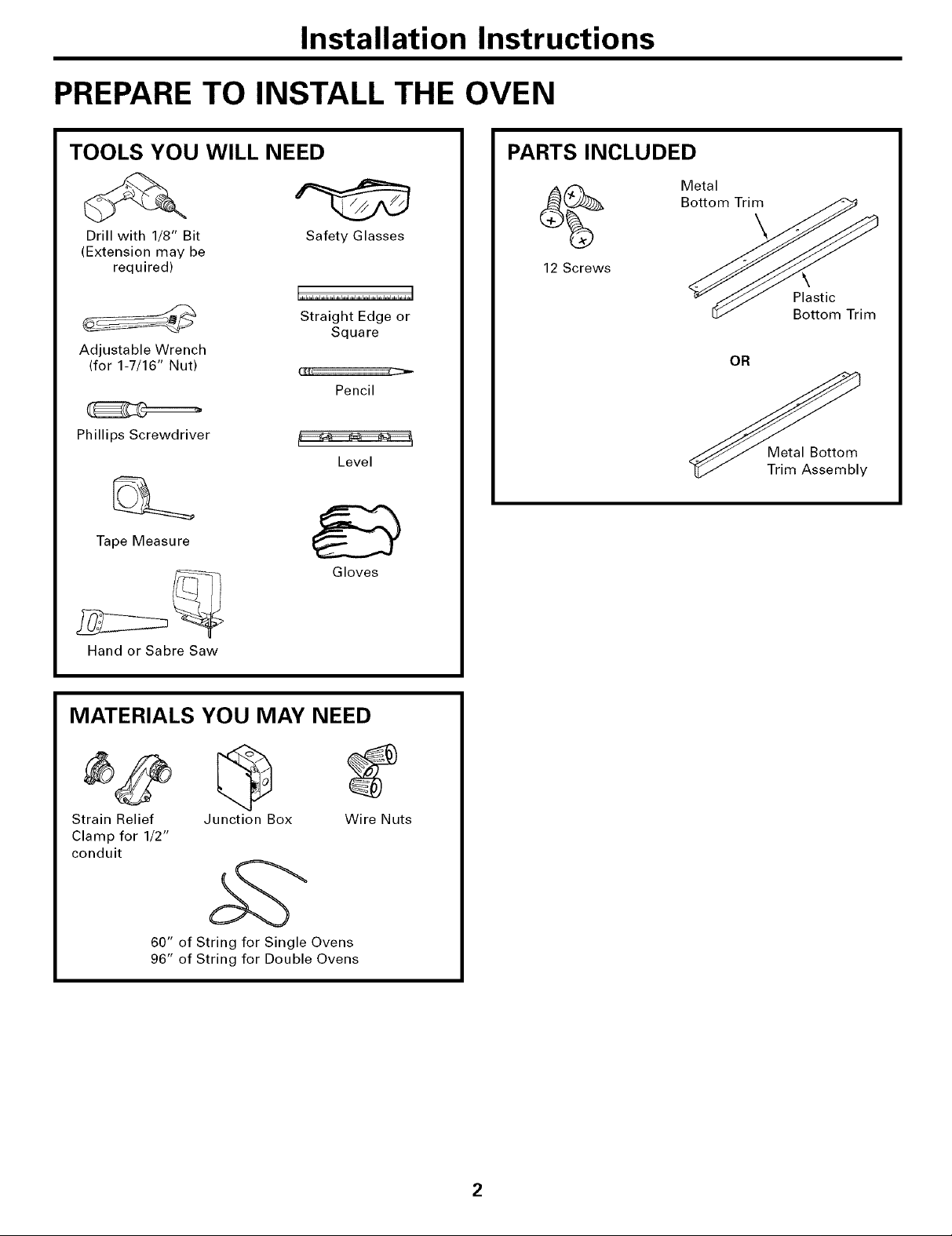
PREPARE TO INSTALL THE OVEN
TOOLS YOU WILL NEED
Drill with 1/8" Bit
(Extension may be
required)
Adjustable Wrench
(for 1-7/16" Nut)
Phillips Screwdriver
Tape Measure
Safety Glasses
Straight Edge or
Square
Pencil
Level
Gloves
PARTS INCLUDED
Metal
Bottom Trim
12 Screws
Plastic
Bottom Trim
OR
Metal Bottom
Trim Assembly
Hand or Sabre Saw
MATERIALS YOU MAY NEED
Strain Relief Junction Box Wire Nuts
Clamp for 1/2"
conduit
60" of String for Single Ovens
96" of String for Double Ovens
2
Page 3
Installation Instructions
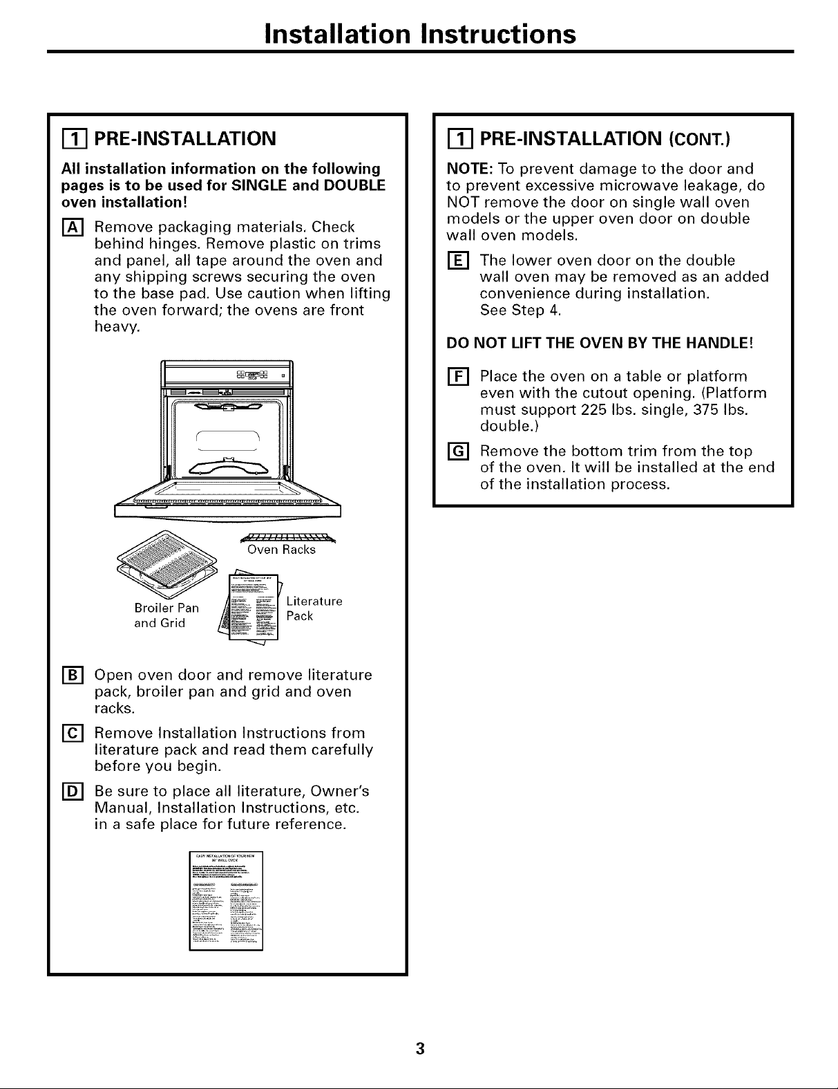
Ill PRE-INSTALLATION
All installation information on the following
pages is to be used for SINGLE and DOUBLE
oven installation!
[] Remove packaging materials. Check
behind hinges. Remove plastic on trims
and panel, all tape around the oven and
any shipping screws securing the oven
to the base pad. Use caution when lifting
the oven forward; the ovens are front
heavy.
_D DD
OB_E_ OD
A =
Ill PRE-INSTALLATION (CONT.)
NOTE: To prevent damage to the door and
to prevent excessive microwave leakage, do
NOT remove the door on single wall oven
models or the upper oven door on double
wall oven models.
[] The lower oven door on the double
wall oven may be removed as an added
convenience during installation.
See Step 4.
DO NOT LIFT THE OVEN BY THE HANDLE!
[]
Place the oven on a table or platform
even with the cutout opening. (Platform
must support 225 Ibs. single, 375 Ibs.
double.)
Remove the bottom trim from the top
[]
of the oven. It will be installed at the end
of the installation process.
Oven Racks
Broiler Pan
and Grid
[] Open oven door and remove literature
pack, broiler pan and grid and oven
racks.
[] Remove Installation Instructions from
literature pack and read them carefully
before you begin.
[] Be sure to place all literature, Owner's
Manual, Installation Instructions, etc.
in a safe place for future reference.
_ iterature
Pack
3
Page 4
Installation Instructions
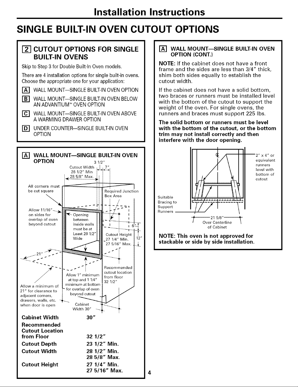
SINGLE BUILT-IN OVEN CUTOUT OPTIONS
CUTOUT OPTIONS FOR SINGLE
BUILT-IN OVENS
Skip to Step 3 for Double Built-In Oven models.
There are 4 installation options for single built-in ovens.
Choose the appropriate one for your application:
[] WALL MOUNTiSINGLE BUILT-IN OVEN OPTION
[] WALL MOUNTiSINGLE BUILT-IN OVEN BELOW
AN ADVANTIUM TM OVEN OPTION
[] WALL MOUNTiSINGLE BUILT-IN OVEN ABOVE
A WARMING DRAWER OPTION
[] UNDER COUNTERiSINGLE BUILT-IN OVEN
OPTION
[] WALL MOUNT--SINGLE BUILT-IN OVEN
OPTION
Cutout Width
28 1/2" Min
_28 5/8" Max. a
All corners must
be cut square
3
/2"
Required Junction
Box Area
-....
Allow 11/16"--..9_
on sides for
overlap of oven
beyond cutout
Opening
between
inside walls
must be at
Least 28 1/2"
Wide
Cutout Height _2'27 1/4" Min.
-27 5/16" Max.
[] WALL MOUNT--SINGLE BUILT-IN OVEN
OPTION (CONT.)
NOTE: If the cabinet does not have a front
frame and the sides are less than 3/4" thick,
shim both sides equally to establish the
cutout width.
If the cabinet does not have a solid bottom,
two braces or runners must be installed level
with the bottom of the cutout to support the
weight of the oven. For single ovens, the
runners and braces must support 225 Ibs.
The solid bottom or runners must be level
with the bottom of the cutout, or the bottom
trim may not install correctly and then
interfere with the door opening.
equivalent
runners
level with
bottom of
cutout
Suitable
Bracing to
Support
Runners
-f---_Ove 21 5/8"-----_
r Centerline \
of Cabinet
NOTE: This oven is not approved for
stackable or side by side installation.
_j 21" _3v_
Allow a minimum of
21" for clearance to
adjacent corners,
drawers, walls, etc.
when door is open
Cabinet Width
Recommended
Cutout Location
from Floor
Cutout Depth
Cutout Width
Cutout Height
Allow 1" minimum
at top and 1 1/4"
minimum at bottom
"for overlap of oven
beyond cutout
Cabinet
Width 30"
30"
32 1/2"
23 1/2" Min.
28 1/2" Min.
28 5/8" Max.
27 1/4" Min.
27 5/16" Max.
Recommended
cutout location
from floor
32 1/2"
4
Page 5
Installation Instructions
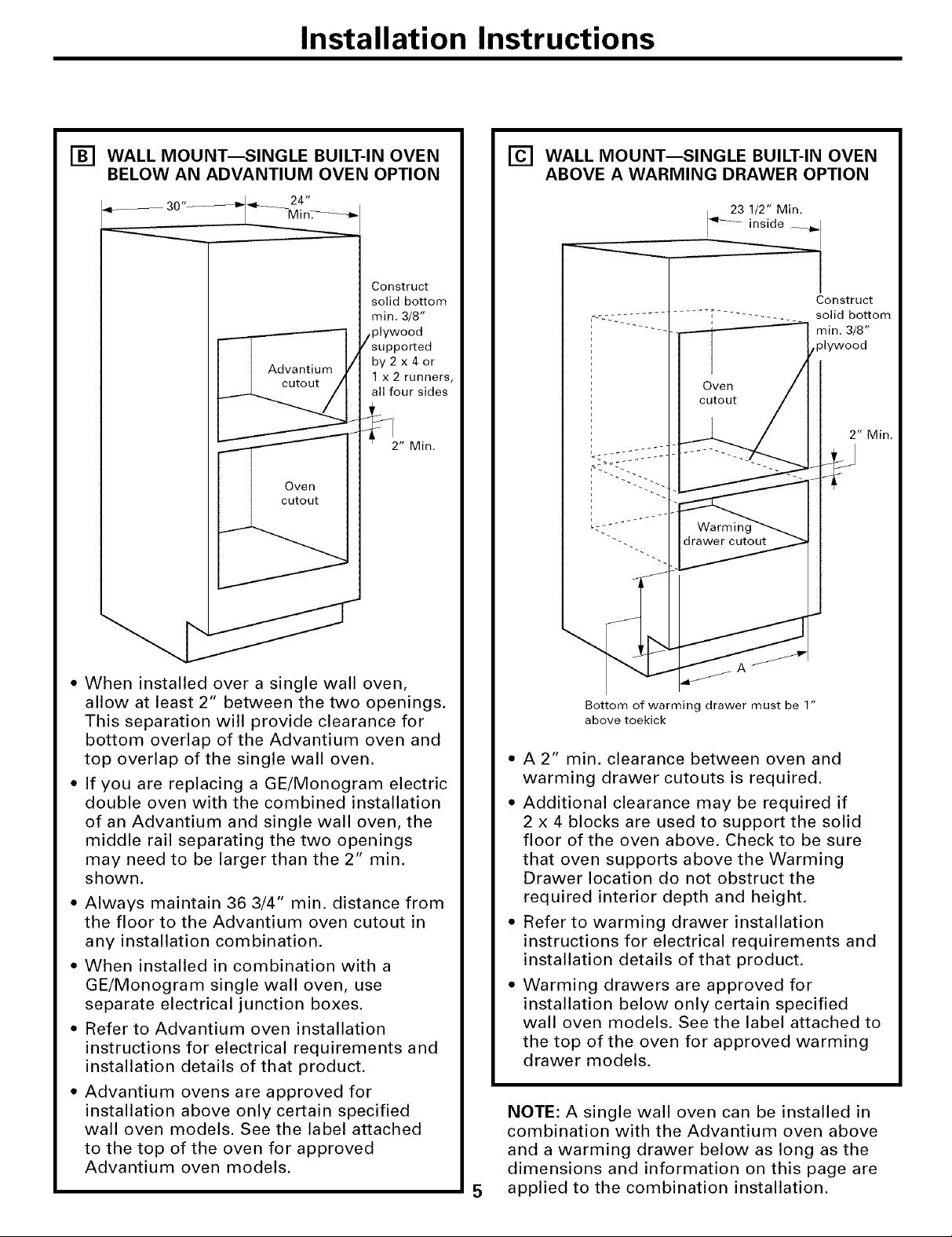
[] WALL MOUNT--SINGLE BUILT-IN OVEN
BELOW AN ADVANTIUM OVEN OPTION
30"_-_ 24"
I Mt n_-_
Construct
solid bottom
min. 3/8"
plywood
supported
by2x4or
1 x 2 runners,
all four sides
2" Min.
[] WALL MOUNT--SINGLE BUILT-IN OVEN
ABOVE A WARMING DRAWER OPTION
inside __
23 /2" Min. _-
.
Construct
solid bottom
min. 3/8"
plywood
2" Min.
• When installed over a single wall oven,
allow at least 2" between the two openings.
This separation will provide clearance for
bottom overlap of the Advantium oven and
top overlap of the single wall oven.
• If you are replacing a GE/Monogram electric
double oven with the combined installation
of an Advantium and single wall oven, the
middle rail separating the two openings
may need to be larger than the 2" min.
shown.
• Always maintain 36 3/4" min. distance from
the floor to the Advantium oven cutout in
any installation combination.
• When installed in combination with a
GE/Monogram single wall oven, use
separate electrical junction boxes.
• Refer to Advantium oven installation
instructions for electrical requirements and
installation details of that product.
• Advantium ovens are approved for
installation above only certain specified
wall oven models. See the label attached
to the top of the oven for approved
Advantium oven models.
Bottom of warming drawer must be 1"
above toekick
• A 2" min. clearance between oven and
warming drawer cutouts is required.
• Additional clearance may be required if
2 x 4 blocks are used to support the solid
floor of the oven above. Check to be sure
that oven supports above the Warming
Drawer location do not obstruct the
required interior depth and height.
• Refer to warming drawer installation
instructions for electrical requirements and
installation details of that product.
• Warming drawers are approved for
installation below only certain specified
wall oven models. See the label attached to
the top of the oven for approved warming
drawer models.
NOTE: A single wall oven can be installed in
combination with the Advantium oven above
and a warming drawer below as long as the
dimensions and information on this page are
applied to the combination installation.
5
Page 6
Installation Instructions
SINGLE BUILT-IN OVEN CUTOUT OPTIONS (CONT.)
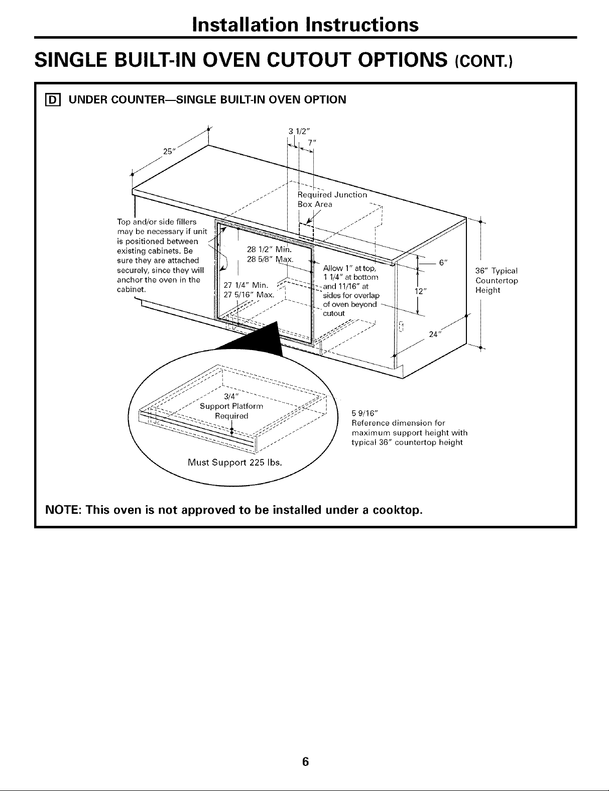
[] UNDER COUNTER--SINGLE BUILT-IN OVEN OPTION
Top and/or side fillers
may be necessary if unit
is positioned between
existing cabinets. Be
sure they are attached
securely, since they will
anchor the oven in the
cabinet.
1 1/4" at bottom
_.:and 11/16" at
sides for overlap
of oven beyond
cutout
P,
36" Typical
Countertop
Height
5 9/16"
Reference dimension for
maximum support height with
typical 36" countertop height
Must Support 225 Ibs.
NOTE: This oven is not approved to be installed under a cooktop.
6
Page 7
Installation Instructions
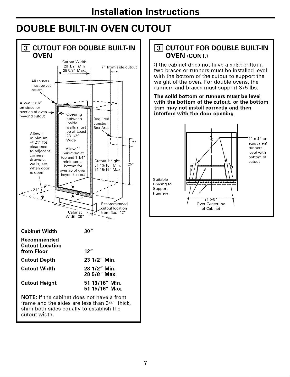
DOUBLE BUILT-IN OVEN CUTOUT
I-_ CUTOUT FOR DOUBLE BUILT-IN
OVEN
Cutout Width
All corners
must be cut
square
Allow 11/16"_
on sides for
overlap of oven --_
beyond cutout
Allow a
minimum
of 21" for
clearance
to adjacent
corners,
drawers,
walls, etc.
when door
is open
28 1/2" Min
28 5/8" Max.
Opening
between
inside
walls mus
be at Least
28 1/2"
Wide
Allow 1"
minimum at
top and 1 1/4"
minimum at
bottom for
overlap of oven
beyond cutout
Cabinet
Width 30"
7" from side cutout
I
Require(
Junction
Box Are_ I
\ ,
I _7"
I
I
Cutout Height
51 13/16" Min. 25"
51 15/16" Max.
Recommended
floor 12"
E_ CUTOUT FOR DOUBLE BUILT-IN
OVEN (CONT.)
If the cabinet does not have a solid bottom,
two braces or runners must be installed level
with the bottom of the cutout to support the
weight of the oven. For double ovens, the
runners and braces must support 375 Ibs.
The solid bottom or runners must be level
with the bottom of the cutout, or the bottom
trim may not install correctly and then
interfere with the door opening.
2" x 4" or
equivalent
runners
level with
bottom of
cutout
Suitable
Bracing to
Support
Runners
-f---_Ove 21 5/8"ili-_
r Centerline \
of Cabinet
Cabinet Width 30"
Recommended
Cutout Location
from Floor 12"
Cutout Depth
Cutout Width
23 1/2" Min.
28 1/2" Min.
28 5/8" Max.
Cutout Height
51 13/16" Min.
51 15/16" Max.
NOTE: If the cabinet does not have a front
frame and the sides are less than 3/4" thick,
shim both sides equally to establish the
cutout width.
Page 8

Installation Instructions
REMOVE THE LOWER OVEN DOOR
ON DOUBLE WALL OVEN MODELS ONLY
To prevent damage
to the door and to
prevent excessive
microwave exposure,
do NOT remove the door on the
single wall oven or the upper oven
door on the double wall oven.
NOTE: The oven door is heavy. You may need
help lifting the door high enough to slide it
into the hinge slots. Do not lift the door by
the handle.
ON DOUBLE WALL OVEN
r_
MODELS, REMOVE THE LOWER
DOOR ONLY:
Fully open the door.
[]
[]
Pull the hinge locks down toward the
door frame, to the unlocked position.
A tool, such as a small flat-blade
screwdriver, may be required.
_-I ON DOUBLE WALL OVEN
MODELS, REMOVE THE LOWER
DOOR ONLY (CONT.)
[] Close door to the door removal position,
which is halfway between the broil stop
position and fully closed.
Removal position
Lift door up and out until the hinge arm
[]
is clear of the slot.
Slot
Him
Pull hinge locks down to unlock
[] Firmly grasp both sides of the door at
the top.
8
Page 9

Installation Instructions
ELECTRICAL CONNECTIONS
ELECTRICAL REQUIREMENTS
This appliance must be supplied with the
proper voltage and frequency, and connected
to an individual, properly grounded branch
circuit, protected by a circuit breaker or fuse
having amperage as noted on rating plate.
(Rating Plate is located on oven frame.)
We recommend you have the electrical wiring
and hookup of your oven connected by a
qualified electrician. After installation, have
the electrician show you where your main
oven disconnect is located.
Check with your local utilities for electrical
codes which apply in your area. Failure to
wire your oven according to governing codes
could result in a hazardous condition. If there
are no local codes, your oven must be wired
and fused to meet the requirements of the
National Electrical Code, ANSI/NFPA No.
70 - Latest Edition. You can get a copy by
writing:
National Fire Protection Association
Batterymarch Park
Quincy, MA 02269
Effective January 1, 1996, the National
Electrical Code requires that new, but not
existing, construction utilize a four-conductor
connection to an electric oven. When
installing an electric oven in new
construction, a mobile home, recreational
vehicle or an area where local codes prohibit
grounding through the neutral conductor,
follow the instructions in the section on NEW
CONSTRUCTION AND FOUR-CONDUCTOR
BRANCH CIRCUIT CONNECTION.
ATTENTION INSTALLER
All electric wall ovens must be hard wired
(direct wired) into an approved junction box.
A plug and receptacle is NOT permitted on
these products.
DO NOT shorten the flexible conduit. The
conduit strain relief clamp must be securely
attached to the junction box and the flexible
conduit must be securely attached to the
clamp. If the flexible conduit will not fit within
the clamp, do not install the oven until a
clamp of the proper size is obtained.
NOTE TO ELECTRICIAN: The 3 power
leads supplied with this appliance are UL
recognized for connection to heavier gauge
household wiring. The insulation of these 3
leads is rated at temperatures much higher
than the temperature rating of household
wiring. The current carrying capacity of the
conductor is governed by the wire gauge and
the temperature rating of the insulation
around the wire.
WARNING: Improper connection
of aluminum house wiring to copper leads
can result in an electrical hazard or fire. Use
only connectors designed for joining copper
to aluminum and follow the manufacturer's
recommended procedure closely.
You must use a three-wire, single-phase
A.C. 208Y/120 Volt or 240/120 Volt, 60 hertz
electrical system. If you connect to aluminum
wiring, properly installed connectors
approved for use with aluminum wiring
must be used.
9
Page 10

Installation Instructions
ELECTRICAL CONNECTIONS (CONT.)
[] TURN OFF ELECTRICITY
Turn off the circuit breaker or remove fuses to
the oven branch circuit.
CONNECT CONDUIT
With the oven supported on a table or
platform in front of the cabinet opening,
connect the flexible conduit to the electrical
junction box as shown below. Position the
conduit in such a manner that it will lie
behind the oven in a natural loop when the
oven is installed. You will need to purchase
an appropriate strain relief clamp to complete
the connection of the conduit to the
junction box.
Junction Box Location
Conduit
Ground
,Wire
[] NEW CONSTRUCTION AND
FOUR-CONDUCTOR BRANCH
CIRCUIT CONNECTION
• When installing in new construction, or
• When installing in a mobile home, or
• When installing in a recreational vehicle, or
• When local codes do not permit grounding
through neutral:
[] Cut the neutral (white) lead from the
crimp. Re-strip the neutral (white) lead to
expose the proper length of conductor.
_tion round Wire
Box Cover
Place oven on
support to assist in
connecting conduit
U
Strain Relief Clamp
included) must be
used at Junction Box
[]
Attach the appliance grounding lead
(green or bare copper) in accordance
with local codes. If the residence
grounding conductor is aluminum,
see WARNING under ATTENTION
INSTALLER.
Connect the oven neutral (white) lead to
[]
the branch circuit neutral (white or gray)
in accordance with local codes, using a
wire nut.
Connect the oven red lead to the branch
[]
circuit red lead and the oven black lead
to the branch circuit black lead in
accordance with local codes, using
wire nuts. If the residence red, black or
white leads are aluminum conductors,
see WARNING under ATTENTION
INSTALLER.
Install Junction Box Cover.
[]
10
Page 11
Installation Instructions
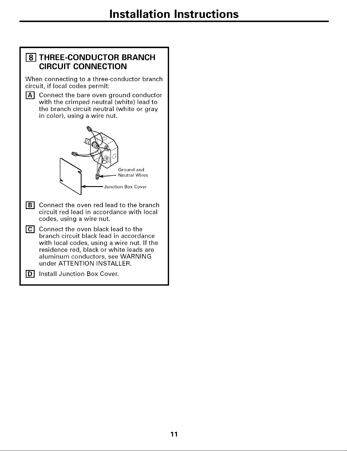
[] THREE-CONDUCTOR BRANCH
CIRCUIT CONNECTION
When connecting to a three-conductor branch
circuit, if local codes permit:
[] Connect the bare oven ground conductor
with the crimped neutral (white) lead to
the branch circuit neutral (white or gray
in color), using a wire nut.
[__Ground and
_-_ 1 _ Neutral Wires
Junction Box Cover
[] Connect the oven red lead to the branch
circuit red lead in accordance with local
codes, using a wire nut.
[] Connect the oven black lead to the
branch circuit black lead in accordance
with local codes, using a wire nut. If the
residence red, black or white leads are
aluminum conductors, see WARNING
under ATTENTION INSTALLER.
[] Install Junction Box Cover.
11
Page 12

Installation Instructions
SECURE THE OVEN IN THE OPENING
[] SLIDE THE OVEN INTO THE
OPENING
Loop (do not tie) the correct length of
[]
string around the conduit before the
oven is slid into place. This will keep the
conduit from falling improperly behind
the oven. For the single wall oven, locate
string toward the middle at the bottom
of the oven. For the double wall oven,
locate string toward the right side at the
bottom of the oven.
Pull out on
<_lm string loop
while pushing
the oven into
the cabinet
[] DRILL THE PILOT HOLES AND
MOUNT THE OVEN
NOTE: Before drilling the pilot holes, make
sure the oven is pushed as far back into the
opening as it will go, is level and is centered.
[] Drill six 1/8" pilot holes through the
mounting holes (top and bottom) of the
side trim, for the #8 screws provided.
Drill ten holes for the Double Oven.
The screws must
Mounting
Hole
be a minimum of
1/4" from the front
of the cutout. (Door
not shown in this
view.)
On a single wall oven, lift the oven into
[]
cabinet cutout using the bottom of the
oven and the bottom of the door as a
grip. Carefully push against the front
edges of the door. On a double wall
oven, lift the oven into cabinet cutout
using the lower oven opening as a grip.
Carefully push against oven front frame.
Do not push against outside edges.
[]
As you slide the oven back, pull the
string so that the conduit will lie behind
the oven in a natural loop.
[]
Once the oven is in the cutout, place the
level on an oven rack inside the oven
to make sure the oven is level from front
to back and from side to side. Use shims
as required.
NOTE: If marks, blemishes or the cutout
opening are visible above the installed oven,
it may be necessary to add wood shims
under the runners and front trim until the
marks or opening are covered.
Once the oven is level and all the way in the
opening, remove the string by pulling on one
end of the loop.
-&WARNING: Mounting screws must
be used. Failure to do so could result in the
oven falling out of the cabinet, causing
serious injury.
[] Secure the oven to cabinet with screws
provided.
NOTE: If the cabinet is particle board, you
must use #8 x 3/4" particle board screws,
These may be purchased at any hardware
store.
12
Page 13

Installation Instructions
To install a single metal bottom trim assembly (on some models), see Step 11.
To install a metal bottom trim with a plastic bottom trim (on some models), see Steps 11 and 12.
INSTALL THE METAL
[]
BOTTOM TRIM
With oven installed, take the bottom trim
[]
and center it on the bottom front edge of
the cabinet opening.
Using the trim as a template, mark the
[]
center of each slot (two total) where the
mounting holes will be drilled.
Remove the trim.
[]
Drill pilot holes into the center of each
[]
template mark.
Place the bottom metal trim over the
[]
pre-drilled mounting holes, making sure
it is centered.
Using trim screws provided, secure the
[]
bottom trim to the bottom edge of the
cabinet. If a plastic bottom trim is
supplied, proceed to Step 12.
r_ INSTALL THE PLASTIC BOTTOM
TRIM (ON SOME MODELS)
[] Make sure flat side is up on the
bottom trim.
[] Find the key slot on the back of the trim.
Key Hole Slot and Wide Flange at Top
plastic
©
Match the key slot with the rivet on the
[]
bottom of the side trim, and lower the
trim onto the rivet.
r
Trim Screws _,
Side
Metal Lower Trim
Single Wall Oven - Door may not be removed.
Trim Screws
\
Side Tr_ml
Double Wall Oven - Lower oven door only may be
IMPORTANT: If this unit is ever removed from
the cabinet or the oven is ever pulled out for
service, the trim must be removed first or
damage to the trim will occur.
\
Metal Lower Trim
removed.
t _Side Trim
_Mi leta iMLot_ tel: TgrRive t on
[]
Push the trim down, at both ends, until it
snaps securely into place.
Push Trim Down at Both Ends
Until it Snaps Securely Into Place
CAUTION: Be sure you do not tip
the oven forward during installation or you
may bend the bottom trim. The bottom trim
provides an opening for cooling air to enter
the cabinet. This opening should never be
blocked.
13
Page 14

Installation Instructions
REPLACE THE LOWER OVEN DOOR
ON DOUBLE WALL OVEN MODELS
[] ON DOUBLE WALL OVEN
MODELS, REPLACE THE LOWER
DOOR:
[] Firmly grasp both sides of the door at
the top.
Bottom
edge of slot
Indentation
, Hinge arm
[] With the door at the same angle as the
removal position, seat the indentation of
the hinge arm into the bottom edge of
the hinge slot. The notch in the hinge
arm must be fully seated into the bottom
of the slot.
[] Fully open the door. If the door will not
fully open, the indentation is not seated
correctly in the bottom edge of the slot.
[] Push the hinge locks up against the front
frame of the oven cavity, to the locked
position.
Hinge
Hinge
Push hinge locks up to lock
[] Close the oven door.
14
Page 15

Installation Instructions
FINAL CHECKLISTS
[] PRE-TEST CHECKLIST
[] Remove all protective film,
[] Check to be sure that all wiring is
secure and not pinched or in contact
with moving parts,
[] Check that the bottom trim is installed
properly (see Steps 11 and 12).
[] Check to be sure the mounting screws
are installed and flush with the side trim
(see Steps 9 and 10).
OPERATION CHECKLIST
[]
Remove all items from the inside of
[]
the oven.
Check that conduit is securely connected
[]
to the junction box.
Turn on the power to the oven. (Refer
[]
to your Owner's Manual,) Verify that the
bake and broil functions make the oven
hot. Verify by feeling heat coming off the
elements within 20 seconds.
[] See your Owner's Manual for
troubleshooting list.
NOTE TO ELECTRICIAN:
The power leads supplied with this appliance
are UL recognized for connections to larger
gauge household wiring. The insulation of
these leads is rated at temperatures much
higher than the temperature rating of
household wiring. The current carrying
capacity of a conductor is governed by the
wire gauge and also the temperature rating
of the insulation around the wire.
NOTE: ALUMINUM WIRING
WARNING: IMPROPER
[]
CONNECTION OF ALUMINUM HOUSE
WIRING TO THE COPPER LEADS CAN
RESULT IN AN ELECTRICAL HAZARD
OR FIRE.
Splice copper wires to aluminum wiring
[]
using special connectors designed and
UL approved for joining copper to
aluminum, and follow the manufacturer's
recommended connector procedure
closely.
NOTE: Wire used, location and enclosure
of splices, etc., must conform to good
wiring practice and local codes.
15
Page 16

16
Printed in the United States
 Loading...