

GE JT910AA1AA, JT910AA2AA, JT910BA1BB, JT910BA2BB, JT910CA1CC Installation Guide
...
Installation
Instructions
30" Built In Wall Oven
JTP15AA, JTP15BA, JTP17SC, JTP18WA, JTP18AA,
JTP18BA, JTP18WA, JTP27BA, JTP27WA, JTP45BA,
JTP45WA, JTP47SC, JTP56AA, JTP56BA, JTP56WA,
JT910AA, JT910BA, JT910CA, JT910SA, JT910WA,
JT950AA, JT950BA, JT950CA, JT950SA, JT950WA,
ZET737BA, ZET737WA, ZET757BA, ZET757WA
Questions? Call GE Answer Center at 800.626.2000 orvisitour
Website at: www.geappliances.com
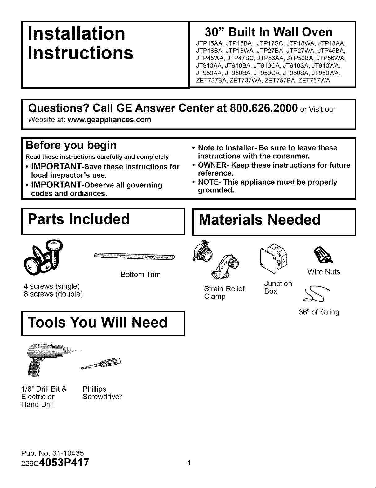
Before you begin
Read these instructions carefully and completely
• IMPORTANT-Save these instructions for
local inspector's use.
• IMPORTANT-Observe all governing
codes and ordiances.
• Note to Installer- Be sure to leave these
instructions with the consumer.
• OWNER- Keep these instructions for future
reference.
• NOTE- This appliance must be properly
grounded.
IPa s.nc.u,e,IIMa,eria.s,ee,e,I
Wire Nuts
36" of String
4 screws (single)
8 screws (double)
Bottom Trim
Junction
Strain Relief Box k_
Clamp
I Tools You Will Need I
1/8" Drill Bit & Phillips
Electric or Screwdriver
Hand Drill
Pub. No. 31-10435
229c4053P417 1
Installation Instructions
IMPORTANT SAFETY INSTRUCTIONS
For Your Safety
• Be sure your oven is installed properly by
a qualified installer or service technician.
• Be sure the oven is securely installed in a
cabinet that is firmly attached to the
house structure. Weight on the oven door
could cause the oven to tip and result in
injury. Never allow anyone to climb, sit,
stand or hang on the oven door.
• Make sure the cabinets and wall cover-
ings around the oven can withstand the
temperatures (up to 200°F.) generated by
the oven.
CAUTION: The electrical power
to the oven supply line must be
shut off while line connections
are being made. Failure to do so
could result in serious injury or
death.
Electrical
Requirements
This appliance must be supplied with the
proper voltage and frequency, and connected
to an individual, properly grounded branch
circuit, protected by a circuit breaker or fuse,
having amperage as noted on rating plate.
(Rating Plate is located on oven frame.)
We recommend you have the electrical wiring
and hookup of your oven connected by a
qualified electrician. After installation, have the
electrician show you where your main range
disconnect is located.
Check with your local utilities for electrical
codes which apply in your area. Failure to
wire your oven according to governing codes
could result in a hazardous condition. If there
are not local codes, your range must be wired
and fused to meet the requirements of the
National Electrical Code, ANSI/NFPA No. 70-
Latest Edition. You can get a copy by writing:
National Fire Protection Association
Battery March Park
Quincy, MA 02269
Effective January 1, 1996, the National
Electrical Code requires that new, but not
existing, construction utilize a 4 conductor
connection to an electric range. When
installing an electric range in new
construction, follow the instructions in the
section on NEW CONSTRUCTION AND
FOUR CONDUCTOR BRANCH CIRCUIT
CONNECTION.
You must use a three-wire, single-phase A.C.
208Y/120 Volt or 240/120 Volt, 60 hertz
electrical system. If you connect to aluminum
wiring, properly installed connectors approved
for use with aluminum wiring must be used.
2

Installation Instructions
Pre-Installation Checklist
ON THE FOLLOWING PAGES ARE III
TO BE USED FOR SINGLE AND III
DOUBLE OVEN INSTALLATION! III
Remove packaging materials.
Check behind hinges, and under
false bottom. Remove labels on
door, plastic on trims and panel,
and all tape around oven.
I_ Open the door to the stop position.
I -- 1
Oven Rack_s
Open oven door and remove literature
pack, broiler pan and grid, and oven
racks.
Remove Installation Instruction from
literature pack and read them carefully
before you begin.
Be sure to place all literature, Use and
Care, Installations, etc. in a safe place
for future reference.
Grasp the door on both sides and
lift up and off the hinges.
NOTE:The oven door is very heavy. Be
sure you have a firm grip before lifting the
oven door off the hinges. Use caution
once the door is removed. Do not lay the
door on its handle. This could cause
dents or scratches
3 (Continued on following page)

Installation Instructions
Pre-Installation Checklist cont
Cover hinge with paper towel rolls
or toweling.
CAUTION: When the door is
removed and the hinge arms
are at the stop postion, DO
NOT bump or try to move the
hinge arms. The hinges could
snap back causing an injury to
the hands. Cover the hinges with
toweling or empty towel rolls
while working in the oven area.
Place the oven on a table or
platform even with the cutout
opening. (Platform must support
150 Ibs. single, 275 Ibs double.)
Remove the bottom trim from the
top of the oven. It will be installed at
the end of installation. The trim is
wrapped separately and taped to the
top of the unit.
Bottom Trim
Shipping Location
, Side Trim
4
Installation Instructions
Cutouts for Single Built-In-Oven
ALLOW 11/16"FOR
OVERLAPOFTHE
OVEN OVER SIDE _
EDGES OF CUTOUT
J 21" _ _ _ _
ALLOW A MINIMUM
OF 21" FOR CLEARANCE
TO ADJACENT CORNERS,
DRAWERS, WALLS ETC.
WHEN THE DOOR IS OPENED.
CUTOUT
WIDTH
_--.-28112"MIN._..,_
285/8"MAX.--
THE OPENING
BETWEEN INSIDE
WALLS MUST
BE AT LEAST
28 1/2"WIDE
ALLOWl"FOR
OVERLAP
ON OVEN TOP
ANDBOTTOM
OFCUTOUT
WIDTH
30"
CUTOUT
HEIGHT
27 1/4" MIN
27 5/16"
RECOMMENDED
CUTOUT
LOCATION
321/2"
FROM THE
FLOOR
I
I
I
JUNCTION BOX
JUNCTION BOX
J LOCATION
22"TO
BOTTOM OF
=
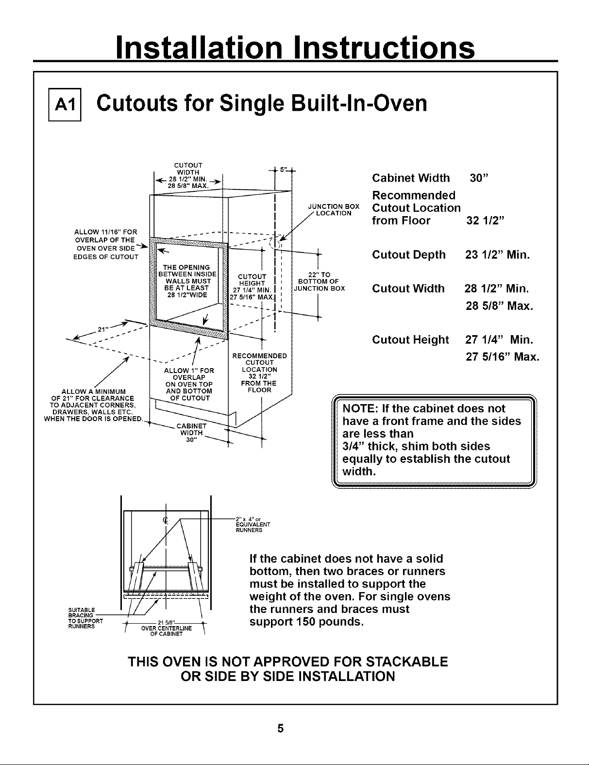
Cabinet Width 30"
Recommended
Cutout Location
from Floor 32 1/2"
Cutout Depth
Cutout Width
23 1/2" Min.
28 1/2" Min.
28 5/8" Max.
Cutout Height 27 1/4" Min.
27 5/16"Max.
NOTE: If the cabinet does not
have a front frame and the sides
are less than
3/4" thick, shim both sides
equally to establish the cutout
width.
SUITABLE
TO SUPPORT
RUNNERS
4" or
EQUIVALENT
RUNNERS
If the cabinet does not have a solid
bottom, then two braces or runners
must be installed to support the
weight of the oven. For single ovens
the runners and braces must
21 5/8"
OVER CENTERLINE
support 150 pounds.
THIS OVEN IS NOT APPROVED FOR STACKABLE
OR SIDE BY SIDE INSTALLATION
 Loading...