

Page 1
Installation
Instructions
30" Built In Wall Oven
JTP15AA, JTP15BA, JTP17SC, JTP18WA, JTP18AA,
JTP18BA, JTP18WA, JTP27BA, JTP27WA, JTP45BA,
JTP45WA, JTP47SC, JTP56AA, JTP56BA, JTP56WA,
JT910AA, JT910BA, JT910CA, JT910SA, JT910WA,
JT950AA, JT950BA, JT950CA, JT950SA, JT950WA,
ZET737BA, ZET737WA, ZET757BA, ZET757WA
Questions? Call GE Answer Center at 800.626.2000 orvisitour
Website at: www.geappliances.com
Before you begin
Read these instructions carefully and completely
• IMPORTANT-Save these instructions for
local inspector's use.
• IMPORTANT-Observe all governing
codes and ordiances.
• Note to Installer- Be sure to leave these
instructions with the consumer.
• OWNER- Keep these instructions for future
reference.
• NOTE- This appliance must be properly
grounded.
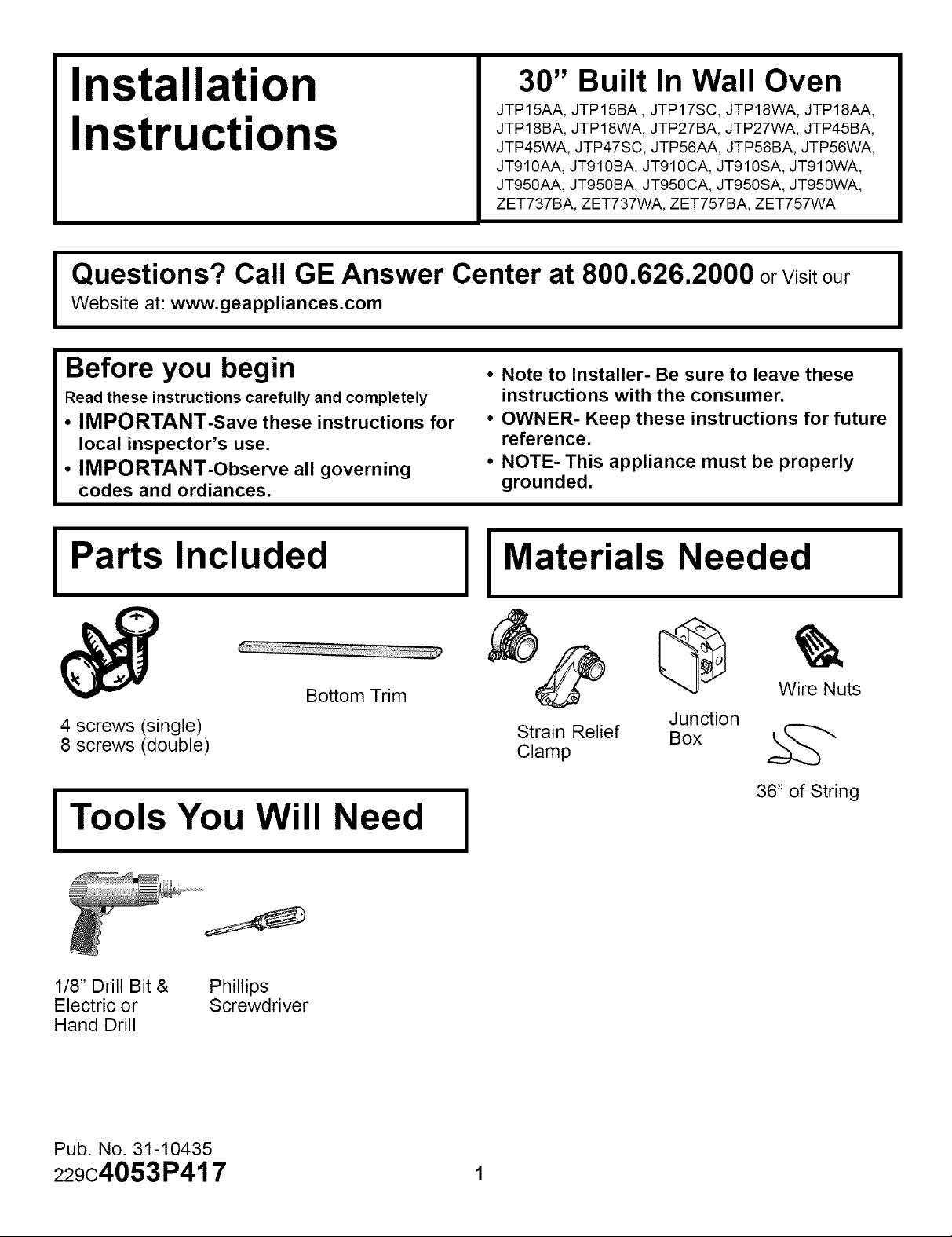
IPa s.nc.u,e,IIMa,eria.s,ee,e,I
Wire Nuts
36" of String
4 screws (single)
8 screws (double)
Bottom Trim
Junction
Strain Relief Box k_
Clamp
I Tools You Will Need I
1/8" Drill Bit & Phillips
Electric or Screwdriver
Hand Drill
Pub. No. 31-10435
229c4053P417 1
Page 2
Installation Instructions
IMPORTANT SAFETY INSTRUCTIONS
For Your Safety
• Be sure your oven is installed properly by
a qualified installer or service technician.
• Be sure the oven is securely installed in a
cabinet that is firmly attached to the
house structure. Weight on the oven door
could cause the oven to tip and result in
injury. Never allow anyone to climb, sit,
stand or hang on the oven door.
• Make sure the cabinets and wall cover-
ings around the oven can withstand the
temperatures (up to 200°F.) generated by
the oven.
CAUTION: The electrical power
to the oven supply line must be
shut off while line connections
are being made. Failure to do so
could result in serious injury or
death.
Electrical
Requirements
This appliance must be supplied with the
proper voltage and frequency, and connected
to an individual, properly grounded branch
circuit, protected by a circuit breaker or fuse,
having amperage as noted on rating plate.
(Rating Plate is located on oven frame.)
We recommend you have the electrical wiring
and hookup of your oven connected by a
qualified electrician. After installation, have the
electrician show you where your main range
disconnect is located.
Check with your local utilities for electrical
codes which apply in your area. Failure to
wire your oven according to governing codes
could result in a hazardous condition. If there
are not local codes, your range must be wired
and fused to meet the requirements of the
National Electrical Code, ANSI/NFPA No. 70-
Latest Edition. You can get a copy by writing:
National Fire Protection Association
Battery March Park
Quincy, MA 02269
Effective January 1, 1996, the National
Electrical Code requires that new, but not
existing, construction utilize a 4 conductor
connection to an electric range. When
installing an electric range in new
construction, follow the instructions in the
section on NEW CONSTRUCTION AND
FOUR CONDUCTOR BRANCH CIRCUIT
CONNECTION.
You must use a three-wire, single-phase A.C.
208Y/120 Volt or 240/120 Volt, 60 hertz
electrical system. If you connect to aluminum
wiring, properly installed connectors approved
for use with aluminum wiring must be used.
2
Page 3

Installation Instructions
Pre-Installation Checklist
ON THE FOLLOWING PAGES ARE III
TO BE USED FOR SINGLE AND III
DOUBLE OVEN INSTALLATION! III
Remove packaging materials.
Check behind hinges, and under
false bottom. Remove labels on
door, plastic on trims and panel,
and all tape around oven.
I_ Open the door to the stop position.
I -- 1
Oven Rack_s
Open oven door and remove literature
pack, broiler pan and grid, and oven
racks.
Remove Installation Instruction from
literature pack and read them carefully
before you begin.
Be sure to place all literature, Use and
Care, Installations, etc. in a safe place
for future reference.
Grasp the door on both sides and
lift up and off the hinges.
NOTE:The oven door is very heavy. Be
sure you have a firm grip before lifting the
oven door off the hinges. Use caution
once the door is removed. Do not lay the
door on its handle. This could cause
dents or scratches
3 (Continued on following page)
Page 4

Installation Instructions
Pre-Installation Checklist cont
Cover hinge with paper towel rolls
or toweling.
CAUTION: When the door is
removed and the hinge arms
are at the stop postion, DO
NOT bump or try to move the
hinge arms. The hinges could
snap back causing an injury to
the hands. Cover the hinges with
toweling or empty towel rolls
while working in the oven area.
Place the oven on a table or
platform even with the cutout
opening. (Platform must support
150 Ibs. single, 275 Ibs double.)
Remove the bottom trim from the
top of the oven. It will be installed at
the end of installation. The trim is
wrapped separately and taped to the
top of the unit.
Bottom Trim
Shipping Location
, Side Trim
4
Page 5
Installation Instructions
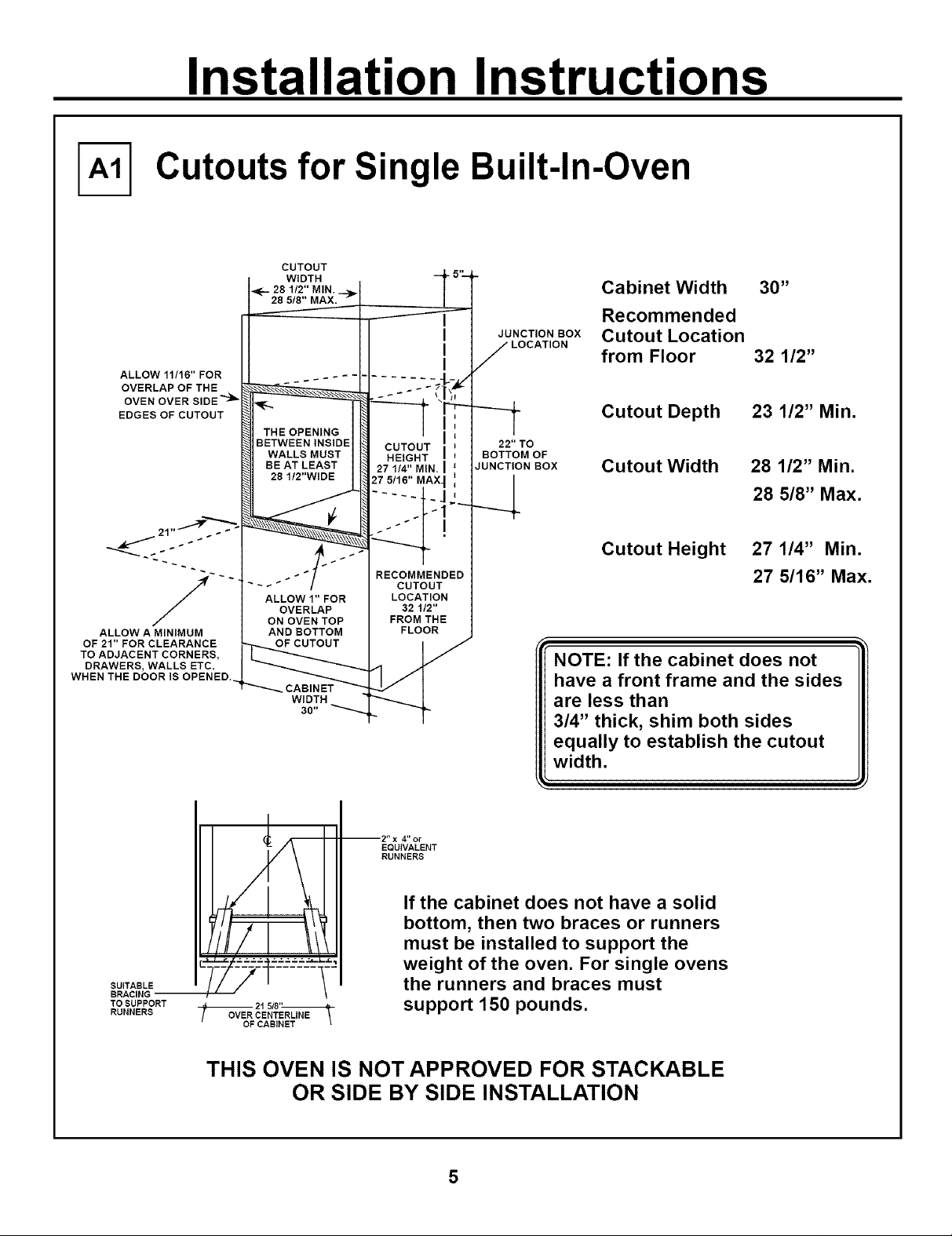
Cutouts for Single Built-In-Oven
ALLOW 11/16"FOR
OVERLAPOFTHE
OVEN OVER SIDE _
EDGES OF CUTOUT
J 21" _ _ _ _
ALLOW A MINIMUM
OF 21" FOR CLEARANCE
TO ADJACENT CORNERS,
DRAWERS, WALLS ETC.
WHEN THE DOOR IS OPENED.
CUTOUT
WIDTH
_--.-28112"MIN._..,_
285/8"MAX.--
THE OPENING
BETWEEN INSIDE
WALLS MUST
BE AT LEAST
28 1/2"WIDE
ALLOWl"FOR
OVERLAP
ON OVEN TOP
ANDBOTTOM
OFCUTOUT
WIDTH
30"
CUTOUT
HEIGHT
27 1/4" MIN
27 5/16"
RECOMMENDED
CUTOUT
LOCATION
321/2"
FROM THE
FLOOR
I
I
I
JUNCTION BOX
JUNCTION BOX
J LOCATION
22"TO
BOTTOM OF
=
Cabinet Width 30"
Recommended
Cutout Location
from Floor 32 1/2"
Cutout Depth
Cutout Width
23 1/2" Min.
28 1/2" Min.
28 5/8" Max.
Cutout Height 27 1/4" Min.
27 5/16"Max.
NOTE: If the cabinet does not
have a front frame and the sides
are less than
3/4" thick, shim both sides
equally to establish the cutout
width.
SUITABLE
TO SUPPORT
RUNNERS
4" or
EQUIVALENT
RUNNERS
If the cabinet does not have a solid
bottom, then two braces or runners
must be installed to support the
weight of the oven. For single ovens
the runners and braces must
21 5/8"
OVER CENTERLINE
support 150 pounds.
THIS OVEN IS NOT APPROVED FOR STACKABLE
OR SIDE BY SIDE INSTALLATION
Page 6

Installation Instructions
Cutouts for Double Built-In-Oven
CUTOUT
WIDTH
_F- 28 1/2" MIN.
28 5/8" MAX.
Cabinet Width 30"
I
ALLOW 11/16"
FOR OVERLAP
OFTHE OVEN
OVER SIDE EDGES
OF CUTOUT
JUNCTION BOX
LOCATION
J
Recommended
Cutout Location
from Floor 12"
Cutout Depth
23 1/2" Min.
ALLOW A MINIMUM OF 21"
FOR CLEARANCE TO
ADJACENT CORNERS,
DRAWERS, WALLS ETC.
WHEN THE DOOR
IS OPENED.
21" _
THE OPENING
BETWEEN INSIDE
WALLS MUST
BE AT LEAST
28 1/2"WIDE
ALLOW 1"FOR
OVERLAP
ON OVEN TOP
AND BOTTOM
OFCUTOUT
CABINET
WIDTH
CUTOUT
HEIGHT
51 13/16" MIN.
51 15/16" MAX.
RECOMMENDED
CUTOUTLOCATION
-12"FROM THE FLOOR
2" x 4" or
EQUIVALENT
RUNNERS
47" TO
BOTTOM OF
/UNCTION BOX
Cutout Wdth
28 1/2" Min.
28 5/8" Max.
Cutout Height
51 13/16" Min.
51 15/16" Max.
NOTE: If the cabinet does not
have a front frame and the
sides are less than
3/4" thick, shim both sides
equally to establish the cutout
width.
SUITABLE
BRACING
TO SUPPORT
RUNNERS
-_'_'_O_ CENTERLINE
OF CABINET
If the cabinet does not have a solid bottom,
then two braces and runners must be
installed to support the weight of the oven.
For double ovens the runners and braces
must support 275 pounds.
Page 7

Installation Instructions
Cutouts For Single Oven Under Counter
Gas or electric cooktops
may be installed over this
oven. See cooktop installation
instructions for cutout size.
See label on top of oven for
approved cooktop models.
\
25 '°
Top and/or side
fillers may be
necessary if
unit is positioned
between existing
cabinets. Be sure
they are attached
securely since
they will anchor
the oven in the
cabinet.
28 1/2" MIN.
28 5/8" MAX.
I
27 1/4" MIN.
27 5/16" MAX.._
4
S #
240V / 208V
Junction Box
Location
Overlap Top
of Oven &
Side Edges
of Cutout
Gas and electrical connections
for 30" gas cooktop must be
located in an adjacent accessible
location to the right. For a 36"
gas cooktop the connections
may be made to the left.
22" MIN.
Above
Support
Platform
fj
24"
36"
Typical
Countertop
Height
t
3/4" Support
Platform
Required
MUST SUPPORT 150 LBS.
5 9/16"
Reference dimension
for maximum support height
with typical 36" countertop
height
NOTE: This Oven is not approved
to be installed under a Solid Disk,
Induction or Downdraft Modular
Cooktop.
i
Page 8

Installation Instructions
Turn off the circuit breaker or remove
fuses to the oven branch circuit.
With the oven in front of the cabinet
opening, on a table or platform, connect
the flexible conduit to the electrical
junction box as shown below. You will
need to purchase a strain relief clamp
to complete the connection of the
conduit to the junction box.
JUNCTION BOX
NC
NEW CONSTRUCTION AND FOUR-
CONDUCTOR BRANCH CIRCUIT
CONNECTION
I'_ • When installing in a new
a.Cut the neutral (White) lead from the crimp.
Re-strip the neutral (white) lead to expose
the proper length of conductor.
construction, or
• When installing oven in a mobile
home, or
• When local codes do not permit
grounding through neutral:
Grounc
/ Wires
Junction
Box Cover
PLACE OVEN ON
A SUPPORT
TO ASSISTIN
CONNECTING
CONDUIT
STRAIN RELIEF CLAMP
( NOT INCLUDED )
MUST BE USED
AT JUNCTION BOX
b.Attach the appliance grounding lead (green
or bare copper) in accordance with local
codes. If the residence grounding conductor
is aluminum, see WARNING note.
c.Connect the oven neutral (white)lead to
the branch circuit neutral (white or gray) in
accordance with local codes, using wire
nut.
d.Connect the oven red lead to the branch
circuit red lead and the oven black lead to
the branch circuit black lead in accordance
with local codes, using wire nuts. If the
residence red, black or white leads are
aluminum conductors, see "WARNING"
note.
e. Install Junction Box Cover.
8 ( Continued on Next Page)
Page 9

Installation Instructions
Electrical Connections cont.
OR
I THREE-CONDUCTORBRANCH I
-_ When connecting to a 3-conductor
a.Connect the bare oven ground conductor
CIRCUIT CONNECTION
branch circuit, if local codes permit:
with the crimped neutral (white) lead to the
branch circuit neutral (white or gray in
color), using wire nut.
Do not shorten the flexible conduit.The
conduit strain Relief Clamp must be
securely attached to the junction box
and the flexible conduit must be
securely attached to the clamp. If the
flexible conduit will not fit within the
clamp, do not install the oven until a
clamp of the proper size is obtained.
NOTE TO ELECTRICIAN: The 3 power
leads supplied with this appliance are UL
recognized for connection to larger gauge
household wiring. The insulation of these 3
leads is rated at temperatures much higher
than the temperature rating of household
wiring. The current carrying capacity of the
conductor is governed by the temperature
rating of the insulation around the wire,
rather than the wire gauge alone.
Junction
-- Box Cover
b.Connect the oven red lead to the branch
circuit red lead, using wire nut.
c. Connect the oven black lead to the branch
circuit black lead in accordance with local
codes, using wire nut.
d.lnstall Junction Box Cover.
_ ARNING: Improper
can result in an electrical hazard or
fire. Use only connectors designed
for joining copper to aluminum and
follow the manufacturer's
recommended procedure closely.
connection of aluminum
house wiring to copper leads
9
Page 10

Installation Instructions
Securing the Oven
I_ With the conduit connected, the oven
is ready to be slid into the cutout
opening.
a. Loop a 36" string around the conduit
before the oven is slid into place. This
will keep the conduit from falling be-
hind the oven.
I, Pull out on
,;_ • string loop
l" while pushing
the oven into
the cabinet
.............. .'\\\\\\\.' ....................... \\ ....
b. Lift oven into cabinet cutout using the
oven opening as an grip. Carefully
push against oven front frame. Do not
push against outside edges.
c. As you slide the oven back, pull the
string so that the conduit will lie on top
of the oven in a natural loop.
d. When you are sure the conduit is out
of the way, slide the oven all the way
back into the opening. Remove the
string.
IC---_ Drill four-I/8" pilot holes through the
mounting holes (top and bottom) of the
side trim, for the four #8 screws
provided. Drill eight holes for the
Double Oven.
The screws must be a
minimum of 1/4" from
the front of the cutout.
MOUNTING
HOLE
LOCATIONS
_--_ Secure the oven to cabinet with screws
provided.
Note: Before drilling the pilot holes
make sure the oven is pushed as far
back into the opening as it will go
and centered.
m n
10
Page 11

Installation Instructions
I-D-1Installing the Bottom Trim
-_ ake sure the flat side is up on the
-_ ind the Key Slot on the back of the
--_ atch the key slot with the rivet on the
--_ Push the trim down until it into
bottom trim.
trim.
bottom of the side trim
snaps
place.
Key hole slot and wide flange at top
\
Lower trim mounting rivet on bottom of side
trim.
Push trim down at both ends until it snaps into
place.
may bend the bottom trim. The bottom trim provides an opening for cooling
[_ AUTION: Be sure you do not tip the oven foward during installation or you [1[
air to enter the cabinet. This opening should never be blocked.
11
Page 12

Installation Instructions
Replacing the Oven Door
Make sure the hinge is in the door stop
position.
Remove the toweling or paper towel holder
from the hinge.
Grasp the door on both sides.
Hold the door over the hinges lining up the
hinges with the hinge slots on the bottom of
the door.
Slide the door down onto the hinges as far
as it will go.
Close the door.
The oven door is heavy. You may need help lifting the door high enough to slide it
down onto the hinges. Do not lift the door by the handle.
12
Page 13

Installation Instructions
Pre-Test Check List
Remove all protective film if
present, and any stickers.
Check to be sure that all wiring is
secure and not pinched or in
contact with moving parts.
Operation Checklist
Remove all items from the inside I_kfl
of the oven.
Turn on the power to the oven.
(Refer to your Use and Care
Manual.) Verify that the bake and
broil units, and all cooking
functionsoperate properly.
Check that the circuit breaker is
not tripped or the house fuse is
blown.
[_ heck that conduit is securely
connected to the junction box.
Check that the bottom trim is installed
properly (see page 11).
Check to be sure the mounting
screws are installed and flush with the
side trim, (see page 10).
NOTE TO ELECTRICIAN:
The power leads supplied with this
appliance are UL recognized for
connections to larger gauge
household wiring. The insulation of
these leads is rated at temperatures
much higher than the temperature
rating of household wiring. The
current carrying capacity of a
conductor is governed by the wire
gauge and also the temperature rating
of the insulation around the wire.
NOTE: ALUMINUM WIRING
A. WARNING:
IMPROPER CONNECTION OF
ALUMINUM HOUSE WIRING TO
THE COPPER LEADS CAN
RESULT IN A SERIOUS PROBLEM.
[_ See Use & Care manual for
troubleshooting list.
B. Splice copper wires to aluminum
wiring using special connectors
designed and UL approved for
joining copper to aluminum and
follow the manufacturer's
recommended connector
procedure closely.
NOTE:Wire used, location and
enclosure of splices, etc., must
conform to good wiring practice and
local codes.
13
Page 14

NOTES
14
Page 15

NOTES
15
Page 16

NOTES
Pub. No. 31-10435
16 229c4053P417
 Loading...